Instruction manual - CAVEX · Instruction manual BA 6612 CAVEX EN 12.11 CAVEX®-worm gear units of...
52
® www.CAVEX-GmbH.de Instruction manual BA 6612 CAVEX EN 12.11 CAVEX ® - worm gear units of the models CD.. Sizes 100 to 630 Instruction manual CAVEX GmbH & Co. KG Tübinger Straße 2 D-72131 Ofterdingen Tel.: +49 (0) 74 73 95 546 - 0 Fax: +49 (0) 74 73 95 546 - 88
Transcript of Instruction manual - CAVEX · Instruction manual BA 6612 CAVEX EN 12.11 CAVEX®-worm gear units of...
®
www.CAVEX-GmbH.de
Instruction manualBA 6612 CAVEX EN 12.11
CAVEX®- worm gear units
of the models CD..
Sizes 100 to 630Instruction manual
CAVEX GmbH & Co. KGTübinger Straße 2D-72131 OfterdingenTel.: +49 (0) 74 73 95 546 - 0Fax: +49 (0) 74 73 95 546 - 88

®
www.CAVEX-GmbH.de
Profit from CAVEX in many ways:
• Continuous range of worm gear units up to 360,000 Nm in 18 sizes
• Specially high torques and efficiencies and long lifetime due to unique gear tooth geometry
• High ratios
• High overload capability
• Rugged design
• Low noise levels
• Custom and sector-specific solutions
• In conformance with ATEX
A worm gear is not just a worm gear. CAVEX proves this over and over again. For more than 50 years. In a wide range of industrial sectors world-wide. The decisive advantage over conventional worm gears is their unique gear tooth geometry.
Intelligent gear tooth geometryThe name CAVEX is well-known and is made up of the Latin word concavus, the worm profile, and convexus, the worm wheel profile. Thanks to the worm teeth with concave flank profile (hollow-flank worm) coupled with convex-shaped worm wheels, CAVEX Worm Gear Units are far superior to compa-rable gear units of the same size. Gear tooth pairing ensures better flank meshing and an extremely low specific gear flank pressure (Hertzian pres-sure). The result: higher torques of up to 360,000 Nm, excellent efficienci-es of up to 95% and a significantly longer lifetime as a result of lower wear.
Complete CAVEX range CAVEX GmbH & Co. KG offers you a complete range of CAVEX Worm Gear Units in 18 sizes from 100 to 360,000 Nm. From single-stage or multi-sta-ge units, in a wide variety of standard versions, as sector-specific solutions or adapted to your specific requirements.
Unique when it comes to efficiency, torque and lifetime
Conventional Worm Gear CAVEX

®
Index of Content
1. Technical data 51.1 Type plate 51.2 Dimension tables 61.2.1 Type CDUW 61.2.2 Type CDOW 71.2.3 Type CDFW 81.2.4 Type CDDA 91.2.5 Type CDUA 101.2.6 Type CDOA 111.2.7 Type CDFA 121.2.8 Worm-gear speed reducer with additional installation surfaces 131.2.9 Worm-gear speed reducer with shrink disc 141.2.10 Installation IEC-engine on double worm-gear speed reducer (size 100 - 630) 151.2.11 Installation IEC-engine on double worm-gear speed reducer (size 100 - 400); drive shaft in position e or g 161.3 Ventilation, oil level, oil drain, oil quantities and weights 171.3.1 Main gear 171.3.2 Primary gear 181.4 Measurement surfaces - Sound pressure level 19
2. General information 192.1 Introduction 192.2 Copyright 19
3. Safety instructions 203.1 Intended use 203.2 General obligations 203.3 Environmental protection 203.4 Special hazards 213.5 Warning notices and symbols in these operating instructions 21
4. Transport and storage 214.1 Scope of delivery 214.2 Transport 214.3 Storing the gear 224.4 Standard preservation 224.5 Rating plates 224.6 Paint 234.6.1 Miscellaneous 234.6.2 Lacquered version 234.6.3 Primed version 24
5. Technical description 255.1 Miscellaneous 255.2 Identification 255.3 Ventilator 255.4 Coupling 255.5 Shrink disc 255.6 Backstop 255.7 Installation of IEC-engines 26
6. Assembly 266.1 General assembly information 266.2 Description of the assembly 266.3 Assembly of a slip-on gear with key 276.3.1 Preparation 276.3.2 Assembly 28
BA 6612 CAVEX EN 12.113 / 49

BA 6612 CAVEX EN 12.114 / 49
®
6.4 Assembly of a slip-on gear with shrink disc 286.4.1 Preparation 286.4.2 Installation 286.4.3 Axial securing 296.4.4 Assembly of the shrink disc 296.4.5 Disassembly of the shrink disc 306.4.6 Cleaning and lubrication of the shrink disc 306.5 Torque support 316.6 Installation of engines 316.6.1 Installation on engine lantern with coupling 31
7. Start up 327.1 Oil filling 327.2 Lubrication of bearings 327.3 Parts and additional parts 327.3.1 Gear with backstop 327.4 Electrical connection (for CAVEX®-gears with installed engine) 337.5 Start up 33
8. Operation 33
9. Interferences, causes, and elimination 349.1 General assembly information 349.2 Possible interferences 34
10. Maintenance and service 3510.1 General maintenance specifications 3510.2 Description of the maintenance and service work 3610.2.1 Oil change 3610.2.2 Greases 3710.2.3 Cleaning the ventilator and casing 3710.2.4 Check mounting screws for tightness 3710.3 Lubricants 3710.3.1 Oil types 38
11. Spare part storage, customer service addresses 3911.1 Spare part storage 3911.2 Spare part lists 4011.2.1 Type CD.W and CD.A 4011.3 Spare part drawings 4111.3.1 Type CD.W 100-160 4111.3.2 Type CD.W 180-250 4211.3.3 Type CD.W 280-500 4311.3.4 Type CD.W 560-630 4411.3.5 Type CD.A 100-160 4511.3.6 Type CD.A 180-250 4611.3.7 Type CD.A 280-500 4711.3.8 Type CD.A 560-630 48
12. Declaration of Manufacturer 49

1. Technical data
1.1 Type plate The type plate of the CAVEX® gear unit includes the following technical data.
including Main gear Primary gear
Further data is listed in the delivery contract and in this instruction manual.
The dimensions of the following measurement tables for the listed models and sizes are applicable to a standard gear unit.
12
®
BA 6612 CAVEX EN 12.115 / 49
Serial number
1 Company logo
Production date
Serial number
Model / Size
Output torque T2N in Nm
Output torque T2max in Nm
Input speed n1 in min-1
Ratio
Oil type/Oil viscosity in ISO VG – Category for the main gear unit
Oil quantity in litres for the main gear unit
Number of the instruction manual
Special data
2
9
8
7
3
104
115
126
SideA
SideB A B
SUA B
B
A
X
View X
SO
B A
A
B
SR SL VO VU
B
A
B
A
f
e
b
c d
a
g
h
a
b
ge
ee
Sizea b c d1 l1 d2 l2 e4 e6 e7 E E1 g1 G1 G2 h1 h2 H m1 m2 m3 s
mm
100 120 140
216 254 290
200235260
28 32 36
18 k618 k622 k6
35 35 40
48 m6 55 m6 65 m6
80 95105
119119140
155180203
262 283 334
100120140
63 63 80
189210245
85 85102
102120132
153168195
190 225 255
309 364 416
170 200 230
170200225
–––
151919
160 180 200
324 364 396
295325350
40 45 50
22 k628 m628 m6
40 50 50
70 m6 80 m6 90 m6
120140160
140168168
224249269
353 400 418
160180200
80100100
264298316
102124124
150165178
210240250
290 320 350
472 522 573
260 290 315
255280295
–––
192424
225 250 280
440 480 525
380415450
55 60 65
32 m632 m638 m6
55 55 60
100 m6110 n6120 n6
180200220
194194220
294321299
466 491 550
225250280
120120140
351376423
145145165
195212230
285300340
390 430 480
638 703 786
350 385 430
325355385
–––
282835
315 355 400
590 665 748
490535585
70 78 85
42 m648 m655 m6
70 80 90
140 n6150 n6170 n6
240260290
244272294
334376419
611 679 741
315355400
160180200
469525576
184205223
252275300
375420460
530 595 660
870 9771086
480 540 605
420460510
–––
354242
450 500
855 955
562616
92100
60 m665 m6
100105
190 n6210 n6
320350
323354
475530
835 922
450500
225250
653726
245270
332365
515565
740 815
12701410
750 840
495540
560630
3542
560 630
10501175
678750
110120
70 m675 m6
110120
230 n6255 n6
390430
387430
589644
10111121
560630
280315
798888
318355
400440
630700
9101015
15601745
9201030
600660
700780
4248
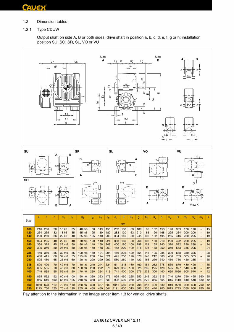
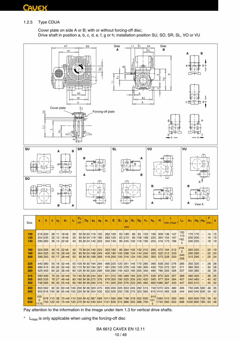
Pay attention to the information in the image under item 1.3 for vertical drive shafts.
®
1.2 Dimension tables
1.2.1 Type CDUW
Output shaft on side A, B or both sides; drive shaft in position a, b, c, d, e, f, g or h; installation position SU, SO, SR, SL, VO or VU
BA 6612 CAVEX EN 12.116 / 49
SideA
SideB A B
SUA B
B
A
X
View X
SO
B A
A
B
SR SL VO VU
B
A
B
A
f
e
b
c d
a
g
h
a
b
ge
ee
Sizea b c d1 l1 d2 l2 e4 e6 e7 E E1 g1 G1 G2 h1 h2 H m1 m2 m3 s
mm
100 120 140
216 254 290
200235260
28 32 36
18 k618 k622 k6
35 35 40
48 m6 55 m6 65 m6
80 95105
119119140
155180203
262 283 334
100120140
63 63 80
189210245
85 85102
102120132
153168195
190 225 255
309 364 416
170 200 230
170200225
–––
151919
160 180 200
324 364 396
295325350
40 45 50
22 k628 m628 m6
40 50 50
70 m6 80 m6 90 m6
120140160
140168168
224249269
353 400 418
160180200
80100100
264298316
102124124
150165178
210240250
290 320 350
472 522 573
260 290 315
255280295
–––
192424
225 250 280
440 480 525
380415450
55 60 65
32 m632 m638 m6
55 55 60
100 m6110 n6120 n6
180200220
194194220
294321299
466 491 550
225250280
120120140
351376423
145145165
195212230
285300340
390 430 480
638 703 786
350 385 430
325355385
–––
282835
315 355 400
590 665 748
490535585
70 78 85
42 m648 m655 m6
70 80 90
140 n6150 n6170 n6
240260290
244272294
334376419
611 679 741
315355400
160180200
469525576
184205223
252275300
375420460
530 595 660
870 9771086
480 540 605
420460510
–––
354242
450 500
855 955
562616
92100
60 m665 m6
100105
190 n6210 n6
320350
323354
475530
835 922
450500
225250
653726
245270
332365
515565
740 815
12701410
750 840
495540
560630
3542
560 630
10501175
678750
110120
70 m675 m6
110120
230 n6255 n6
390430
387430
589644
10111121
560630
280315
798888
318355
400440
630700
9101015
15601745
9201030
600660
700780
4248
Pay attention to the information in the image under item 1.3 for vertical drive shafts.
®
1.2 Dimension tables
1.2.1 Type CDUW
Output shaft on side A, B or both sides; drive shaft in position a, b, c, d, e, f, g or h; installation position SU, SO, SR, SL, VO or VU
BA 6612 CAVEX EN 12.116 / 49
SideB
SideA
B A
Mounting with pin screws and nuts
X
View X
SU
A B
B
A
SO
SR
A
B
SL VO VU
B
A
B
A
B A
g e
h f
d c
b a
a
b
f h
ff
Sizea b c d1 l1 d2 l2 e4 e6 e7 E E1 g1 G1 G2 h1 h2 H m1 m2 m3 s
mm
100 120 140
216 254 290
200235260
28 32 36
18 k618 k622 k6
35 35 40
48 m6 55 m6 65 m6
80 95105
119119140
155180203
262 283 334
100120140
63 63 80
189210245
85 85102
102120132
182 227 255
145 170 195
335 395 450
170 200 230
170200225
–––
151919
160 180 200
324 364 396
295325350
40 45 50
22 k628 m628 m6
40 50 50
70 m6 80 m6 90 m6
120140160
140168168
224249269
353 400 418
160180200
80100100
264298316
102124124
150165178
300 325 370
220 245 270
510 565 620
260 290 315
255280295
–––
192424
225 250 280
440 480 525
380415450
55 60 65
32 m632 m638 m6
55 55 60
100 m6110 n6120 n6
180200220
194194220
294321299
466 491 550
225250280
120120140
351376423
145145165
195212230
405 460 507
300 330 367
690 760 847
350 385 430
325355385
–––
282835
315 355 400
590 665 748
490535585
70 78 85
42 m648 m655 m6
70 80 90
140 n6150 n6170 n6
240260290
244272294
334376419
611 679 741
315355400
160180200
469525576
184205223
252275300
560 690 705
405 455 505
93510501165
480 540 605
420460510
–––
354242
450 500
855 955
562616
92100
60 m665 m6
100105
190 n6210 n6
320350
323354
475530
835 922
450500
225250
653726
245270
332365
755 845
530 595
12701410
750 840
495540
560630
3542
560 630
10501175
678750
110120
70 m675 m6
110120
230 n6255 n6
390430
387430
589644
10111121
560630
280315
798888
318355
400440
9301045
650 730
15601745
9201030
600660
700780
4248
Pay attention to the information in the image under item 1.3 for vertical drive shafts.
®
BA 6612 CAVEX EN 12.117 / 49
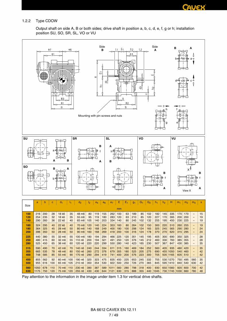
1.2.2 Type CDOW
Output shaft on side A, B or both sides; drive shaft in position a, b, c, d, e, f, g or h; installation position SU, SO, SR, SL, VO or VU

SideA
SideB
Mounting with pin screws and nuts Hole pattern for size
A B
SU A B
B
A
B A
SO
SR SL VO
A
B
VU
B
A
B
A
X
View X
ba
dc
eg
fh
a
b
f h
ff
c d1 l1 d2 l2 d3d4
e1 e2 e4 e6 e E E1 g1 g3 G1 G2 k s zSize
c d1 l1 d2 l2 d3h8
e1 e2 e4 e6 e7 E E1 g1 g3 G1 G2 k s z
mm
100 120 140
91011
18 k618 k622 k6
35 35 40
48 m6 55 m6 65 m6
80 95105
266 315 360
220 260 305
90105115
119139161
119119140
155180203
262 283 334
100120140
63 63 80
189210245
107125138
85 85102
102120132
245 290 335
8 x 11 8 x 13.5 8 x 13.5
455
160 180 200
121314
22 k628 m628 m6
40 50 50
70 m6 80 m6 90 m6
120140160
410 450 490
340 380 420
130140150
182202223
140168168
224249269
353 400 418
160180200
80100100
264298316
157172185
102124124
150165178
380 420 460
8 x 17.5 8 x 17.5 8 x 17.5
555
225 250 280
1516.518
32 m632 m638 m6
55 55 60
100 m6110 n6120 n6
180200220
540 590 665
465 515 575
165180200
248273306
194194220
294321299
466 491 550
225250280
120120140
351376423
202220238
145145165
195212230
505 555 625
12 x 17.512 x 17.512 x 22
566
315 355 400
19.521
22.5
42 m648 m655 m6
70 80 90
140 n6150 n6170 n6
240260290
730 825 910
640 725 805
215240260
340382426
244272294
334376419
611 679 741
315355400
160180200
469525576
260286312
184205223
252275300
690 780 865
12 x 2212 x 2612 x 26
666
450 500
2425.5
60 m665 m6
100105
190 n6210 n6
320350
10251150
9051015
290315
530595
323354
475530
835 922
450500
225250
653726
345389
245270
332365
9751095
16 x 2616 x 33
66
560 630
2728.5
70 m675 m6
110120
230 n6255 n6
390430
12701405
11251260
350385
650730
387430
589644
10111121
560630
280315
798888
415456
318355
400440
12101345
16 x 3316 x 33
66
Pay attention to the information in the image under item 1.3 for vertical drive shafts.
®
BA 6612 CAVEX EN 12.118 / 49
1.2.3 Types CDFW
Flange on side A, B or both sides; drive shaft on side A, B or both sides: Drive shaft in position a, b, c, d, e, f, g or h; installation position SU, SO, SR, SL, VO or VU
SideA
SideB
Cover plate
Detail X
End plate
A B
X
View X
SU A B
B
A
SO
B A
SR SL VO
A
B
VU
B
A
B
A
1
2
3
2
1
3
a
1
3
2
3 232
111
1
32
32
b
c d
e
f
g
h
a
b
f h
ff
c1 c2 d1 l1 d6D2 D5
e1 e2 e4 e6 e E E1 f g1 g4 G1 G2L
L2 nP
sSize
c1 c2 d1 l1 d6H7 H8
e1 e2 e4 e6 e7 E E1 f g1 g4 G1 G2min. max.*
L2 nmin.
s
mm
100 120 140
202025
111214
18 k618 k622 k6
35 35 40
40 50 50
50 60 65
202525
90105115
119139161
119119140
155180203
262 283 334
100120140
63 63 80
333
189210245
88101113
85 85102
93106118
136155173
147167186
165187208.
5
225 270 315
141618
M 16M 20M 20
160 180 200
253232
151617
22 k628 m628 m6
40 50 50
65 65 80
75 85 95
323240
130140150
182202223
140168168
224249269
353 400 418
160180200
80100100
444
264298316
126138148
102124124
132144155
194212228
212233250
235.5
259278
360 405 450
202225
M 20M 20M 24
225 250 280
404040
182022
32 m632 m638 m6
55 55 60
80 80100
105115125
404050
165180200
248273306
194194220
294321299
466 491 550
225250280
120120140
555
351376423
163178192
145145165
170185200
250272293
276301326
307335363
505 560 630
283032
M 24M 24M 24
315 355 400
505060
242730
42 m648 m655 m6
70 80 90
100120120
140160180
506060
215240260
340382426
244272294
334376419
611 679 741
315355400
160180200
555
469525576
212233256
184205223
220242265
322354387
357394433
397438481
710 800 900
364045
M 30M 30M 30
450 500
6075
3336
60 m665 m6
100105
150150
200220
7575
290315
530595
323354
475530
835 922
450500
225250
66
653726
282310
245270
292320
425465
480528
532585
1010
1120
4850
M 30M 36
560 630
7590
3840
70 m675 m6
110120
170170
240270
9090
350385
650730
387430
589644
10111121
560630
280315
66
798888
341377
318355
352388
510560
583650
643713
1260
1420
5663
M 36M 36
Pay attention to the information in the image under item 1.3 for vertical drive shafts.
* Lmax is only applicable when using the forcing-off disc
®
BA 6612 CAVEX EN 12.119 / 49
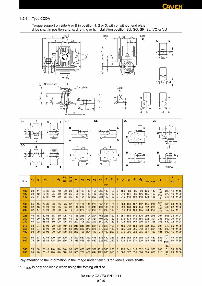
1.2.4 Type CDDA
Torque support on side A or B in position 1, 2 or 3; with or without end plate; drive shaft in position a, b, c, d, e, f, g or h; installation position SU, SO, SR, SL, VO or VU
SideA
SideB
Cover plate Forcing-off plate
A B
X
View X
SUA B
B
ASO
SR SL VO
B A
A
B
VU
B
A
B
A
a
a e
e
b
c d
eg
fh
b
g
e
a b c c2 d1 l1D2
D3 e4 e6 e E E1 g1 G1 G2 h1 h2 HL
L1 m1 m2 m3P
sSize
a b c c2 d1 l1H7
D3 e4 e6 e7 E E1 g1 G1 G2 h1 h2 Hmin. max.*
L1 m1 m2 m3min.
s
mm
100 120 140
216 254 290
200235260
28 32 36
111214
18 k618 k622 k6
35 35 40
50 60 65
M 20M 24M 24
119119140
155180203
262 283 334
100120140
63 63 80
189210245
85 85102
93106118
153168195
190 225 255
309 364 416
136155173
147167186
152173192.
5
170 200 230
170200225
–––
141618
151919
160 180 200
324 364 396
295325350
40 45 50
151617
22 k628 m628 m6
40 50 50
75 85 95
M 24M 24M 30
140168168
224249269
353 400 418
160180200
80100100
264298316
102124124
132144155
210240250
290 320 350
472 522 573
194212228
212233250
218.5
240258
260 290 315
255280295
–––
202225
192424
225 250 280
440 480 525
380415450
55 60 65
182022
32 m632 m638 m6
55 55 60
105115125
M 30M 30M 30
194194220
294321299
466 491 550
225250280
120120140
351376423
145145165
170185200
285300340
390 430 480
638 703 786
250272293
276301326
285311337
350 385 430
325355385
–––
283032
282835
315 355 400
590 665 748
490535585
70 78 85
242730
42 m648 m655 m6
70 80 90
140160180
M 36M 36M 36
244272294
334376419
611 679 741
315355400
160180200
469525576
184205223
220242265
375420460
530 595 660
870 9771086
322354387
357394433
369407447
480 540 605
420460510
–––
364045
354242
450 500
855 955
562616
92100
3336
60 m665 m6
100105
200220
M 36M 36
323354
475530
835 922
450500
225250
653726
245270
292320
515565
740 815
12701410
425465
480528
495544
750 840
495540
560630
4850
3542
560 630
1050
1175
678750
110120
3840
70 m675 m6
110120
240270
M 42M 42
387430
589644
10111121
560630
280315
798888
318355
352388
630700
910101
5
15601745
510560
583650
600668
9201030
600660
700780
5663
4248
Pay attention to the information in the image under item 1.3 for vertical drive shafts.
®
BA 6612 CAVEX EN 12.1110 / 49
* Lmax is only applicable when using the forcing-off disc
1.2.5 Type CDUA
Cover plate on side A or B; with or without forcing-off disc; Drive shaft in position a, b, c, d, e, f, g or h; installation position SU, SO, SR, SL, VO or VU
* Lmax is only applicable when using the forcing-off disc
®
BA 6612 CAVEX EN 12.1111 / 49
SideB
SideA
Cover plate
Forcing-off plate
Mounting with pin screws and nuts
B A
SU
A B
B
A
SO
SR SL VO
A
B
B
A
B
A
VU
X
View X
B A
d c
g e
h f
b a
a
b
f h
ff
a b c c d lD2
D e e e E E g G G h h H m m mL
LP
sSize
a b c c2 d1 l1H7
D3 e4 e6 e7 E E1 g1 G1 G2 h1 h2 H m1 m2 m3min. max.*
L1min.
s
mm
100 120 140
216 254 290
200235260
28 32 36
111214
18 k618 k622 k6
35 35 40
50 60 65
M 20M 24M 24
119119140
155180203
262 283 334
100120140
63 63 80
189210245
85 85102
93106118
182 227 255
145170195
335 395 450
170 200 230
170200225
–––
136155173
147167186
152173192.
5
141618
151919
160 180 200
324 364 396
295325350
40 45 50
151617
22 k628 m628 m6
40 50 50
75 85 95
M 24M 24M 30
140168168
224249269
353 400 418
160180200
80100100
264298316
102124124
132144155
300 325 370
220245270
510 565 620
260 290 315
255280295
–––
194212228
212233250
218.5
240258
202225
192424
225 250 280
440 480 525
380415450
55 60 65
182022
32 m632 m638 m6
55 55 60
105115125
M 30M 30M 30
194194220
294321299
466 491 550
225250280
120120140
351376423
145145165
170185200
405 460 507
300330367
690 760 847
350 385 430
325355385
–––
250272293
276301326
285311337
283032
282835
315 355 400
590 665 748
490535585
70 78 85
242730
42 m648 m655 m6
70 80 90
140160180
M 36M 36M 36
244272294
334376419
611 679 741
315355400
160180200
469525576
184205223
220242265
560 630 705
405455505
935105
01165
480 540 605
420460510
–––
322354387
357394433
369407447
364045
354242
450 500
855 955
562616
92100
3336
60 m665 m6
100105
200220
M 36M 36
323354
475530
835 922
450500
225250
653726
245270
292320
755 845
530595
1270
1410
750 840
495540
560630
425465
480528
495544
4850
3542
560 630
1050
1175
678750
110120
3840
70 m675 m6
110120
240270
M 42M 42
387430
589644
10111121
560630
280315
798888
318355
352388
930104
5
650730
1560
1745
920103
0
600660
700780
510560
583650
600668
5663
4248
Pay attention to the information in the image under item 1.3 for vertical drive shafts.
1.2.6 Type CDOA
Cover plate on side A or B; with or without forcing-off disc; Drive shaft in position a, b, c, d, e, f, g or h; installation position SU, SO, SR, SL, VO or VU

SideA
SideB
Cover plate Forcing-off plate
Hole pattern for size
Slide Bush
A B
X
View X
SUA B
B
ASO
B A
A
B
SR SL VO VU
B
A
B
A
ba
dc
eg
fh
a
b
f h
ff
c c d l dd4 D2
D e e e e e E E g g G G kL
LP
s zSize
c c2 d1 l1 d3h8 H7
D3 e1 e2 e4 e6 e7 E E1 g1 g3 G1 G2 kmin. max.*
L1min.
s z
mm
100 120 140
182022
111214
18 k618 k622 k6
35 35 40
217 258 302
155 190 225
50 60 65
M 20M 24M 24
90105115
119139161
119119140
155180203
262 283 334
100120140
63 63 80
189210245
90104116
85 85102
93106118
195 235 275
136155173
147167186
152173192.
5
141618
8 x M 10 8 x M 12 8 x M 12
3.544
160 180 200
252831
151617
22 k628 m628 m6
40 50 50
338 379 416
260 295 330
75 85 95
M 24M 24M 30
130140150
182202223
140168168
224249269
353 400 418
160180200
80100100
264298316
129142152
102124124
132144155
310 350 385
194212228
212233250
218.5
240258
202225
8 x M 16 8 x M 16 8 x M 16
555
225 250 280
343740
182022
32 m632 m638 m6
55 55 60
462 510 574
375 420 465
105115125
M 30M 30M 30
165180200
248273306
194194220
294321299
466 491 550
225250280
120120140
351376423
167181196
145145165
170185200
430 480 535
250272293
276301326
285311337
283032
12 x M 1612 x M 1612 x M 20
556
315 355 400
434648
242730
42 m648 m655 m6
70 80 90
638 720 804
530 600 680
140160180
M 36M 36M 36
215240260
340382426
244272294
334376419
611 679 741
315355400
160180200
469525576
216238260
184205223
220242265
600 680 760
322354387
357394433
369407447
364045
12 x M 2012 x M 2412 x M 24
666
450 500
5255
3336
60 m665 m6
100105
9061014
770 860
200220
M 36M 36
290315
530595
323354
475530
835 922
450500
225250
653726
287314
245270
292320
860 960
425465
480528
495544
4850
16 x M 2416 x M 24
66
560 630
6063
3840
70 m675 m6
110120
11261258
9651090
240270
M 42M 42
350385
650730
387430
589644
10111121
560630
280315
798888
346382
318355
352388
10701200
510560
583650
600668
5663
16 x M 2416 x M 24
66
Pay attention to the information in the image under item 1.3 for vertical drive shafts.
®
BA 6612 CAVEX EN 12.1112 / 49
* Lmax is only applicable when using the forcing-off disc
1.2.7 Type CDFA
Flange cover on side A or B; with or without forcing-off disc; Drive shaft in position a, b, c, d, e, f, g or h; installation position SU, SO, SR, SL, VO or VU

1.2.8 Worm-gear speed reducer with additional installation surfaces
Size 100 - 400 Size 450 - 630
Mounting surfacesa3 x b3
Mounting surfacesa4 x b4
Sizea3 b3 h3 m3 m4 m7 s3 t
Sizea4 b4 h4 m5 m6 m8 s3 t
mm mm mm mm
100 216 131 115 163 105 – M 12 23 100 216 160 190 170 133 – M 12 23
120 254 155 135 190 125 – M 16 25 120 254 183 225 194 151.5 – M 16 25
140 290 172 156 220 140 – M 16 26 140 290 204 255 220 172 – M 16 26
160 324 189 177 245 155 – M 16 27 160 324 223 290 240 187.5 – M 16 27
180 354 210 197 275 170 – M 20 30 180 364 245 320 268 209.5 – M 20 30
200 396 222 217 300 182 – M 20 31 200 396 260 350 280 219 – M 20 31
225 440 246 242 335 200 – M 24 38 225 440 280 390 300 234.5 – M 24 38
250 480 266 267 370 220 – M 24 40 250 480 305 430 340 265.5 – M 24 40
280 525 296 298 400 240 – M 30 45 280 525 345 480 430 290 – M 30 45
315 590 325 331 450 265 – M 30 45 315 590 370 530 480 310 – M 30 45
355 665 363 373 510 295 – M 36 55 355 665 415 595 540 350 – M 36 55
400 748 403 416 570 335 – M 36 55 400 748 445 660 605 375 – M 36 55
Mounting surfacesa3 x b3
Mounting surfacesa4 x b4
a3 b3 h3 m3 m4 m7 s3 tSize
a4 b4 h4 m5 m6 m8 s3 tSize
mm mm
450 855 562 530 750 495 560 35 92 450 855 562 740 750 495 560 35 92
500 955 616 595 840 540 630 42 100 500 955 616 815 840 540 630 42 100
560 1050 678 650 920 600 700 42 110 560 1050 678 910 920 600 700 42 110
630 1175 750 730 1030 660 780 48 120 630 1175 750 1015 1030 660 780 48 120
®
BA 6612 CAVEX EN 12.1113 / 49
®
BA 6612 CAVEX EN 12.1114 / 49
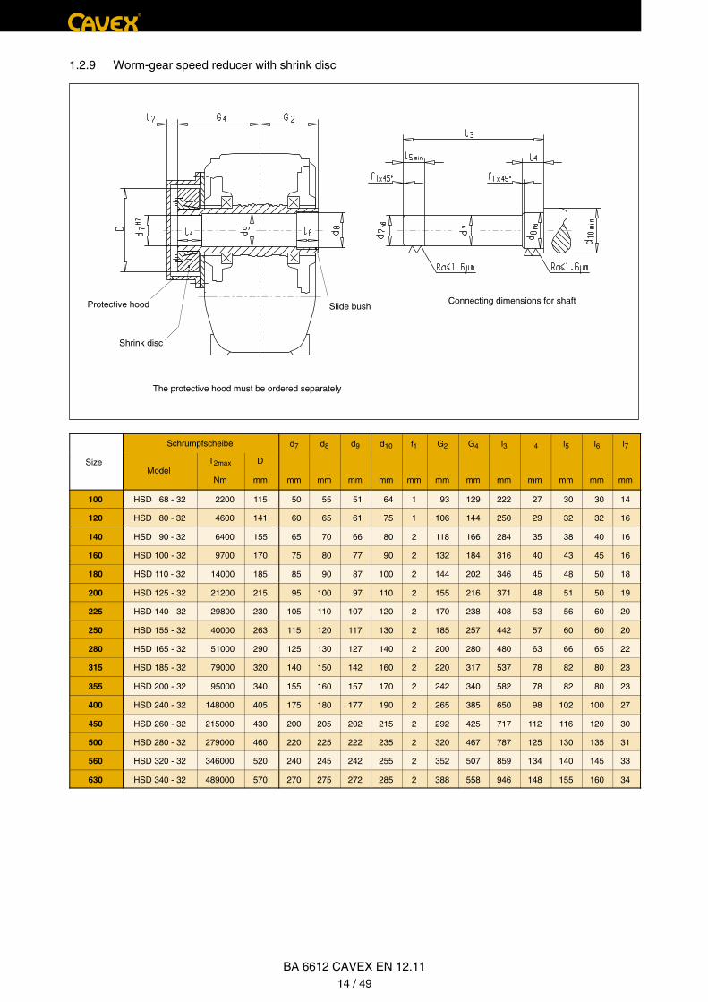
1.2.9 Worm-gear speed reducer with shrink disc
Connecting dimensions for shaft Slide bush
The protective hood must be ordered separately
Shrink disc
Protective hood
Schrumpfscheibe d7 d8 d9 d10 f1 G2 G4 l3 l4 l5 l6 l7
SizeModel
T2max
Nm
D
mm mm mm mm mm mm mm mm mm mm mm mm mm
100 HSD 68 - 32 2200 115 50 55 51 64 1 93 129 222 27 30 30 14
120 HSD 80 - 32 4600 141 60 65 61 75 1 106 144 250 29 32 32 16
140 HSD 90 - 32 6400 155 65 70 66 80 2 118 166 284 35 38 40 16
160 HSD 100 - 32 9700 170 75 80 77 90 2 132 184 316 40 43 45 16
180 HSD 110 - 32 14000 185 85 90 87 100 2 144 202 346 45 48 50 18
200 HSD 125 - 32 21200 215 95 100 97 110 2 155 216 371 48 51 50 19
225 HSD 140 - 32 29800 230 105 110 107 120 2 170 238 408 53 56 60 20
250 HSD 155 - 32 40000 263 115 120 117 130 2 185 257 442 57 60 60 20
280 HSD 165 - 32 51000 290 125 130 127 140 2 200 280 480 63 66 65 22
315 HSD 185 - 32 79000 320 140 150 142 160 2 220 317 537 78 82 80 23
355 HSD 200 - 32 95000 340 155 160 157 170 2 242 340 582 78 82 80 23
400 HSD 240 - 32 148000 405 175 180 177 190 2 265 385 650 98 102 100 27
450 HSD 260 - 32 215000 430 200 205 202 215 2 292 425 717 112 116 120 30
500 HSD 280 - 32 279000 460 220 225 222 235 2 320 467 787 125 130 135 31
560 HSD 320 - 32 346000 520 240 245 242 255 2 352 507 859 134 140 145 33
630 HSD 340 - 32 489000 570 270 275 272 285 2 388 558 946 148 155 160 34
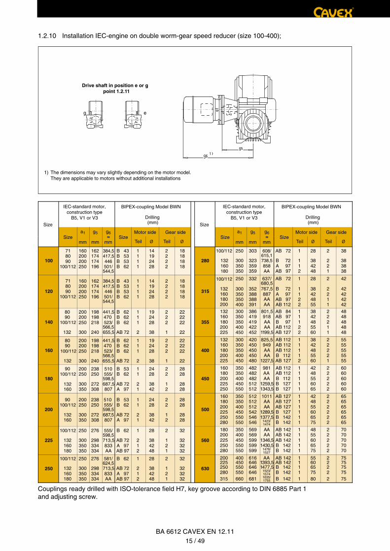
1.2.10 Installation IEC-engine on double worm-gear speed reducer (size 100-400);
1) The dimensions may vary slightly depending on the motor model. They are applicable to motors without additional installations
Drive shaft in position e or g point 1.2.11
eg
Size
IEC-standard motor,construction type
B5, V1 or V3
IEC-standard motor,construction type
B5, V1 or V3
BIPEX-coupling Model BWN
Drilling(mm) Size
BIPEX-coupling Model BWN
Drilling(mm)
Sizea1 g5 g6
≈Motor side Gear side
Sizea1 g5 g6
≈ SizeMotor side Gear side
mm mm≈
mmSize
Teil Ø Teil Ø mm mm≈
mm Teil Ø Teil Ø
100
160200200250
718090
100/112
71 100/112
8090
100/112
100/112
132160180
162174174196
384,5417,5446501/544,5
384,5
446417,5
501/544,5
523/566,5
523/566,5
555/598,5
555/598,5
555/598,5
581/624,5
608/615,1738,5858AA
B 43B 53B 53B 62
1111
14192428
2222
18181818
280
250
300350350
303
323359359
AB 72
B 72A 97AB 97
1
112
28
384248
2
221
38
383838
120
160200200250
162174174196
B 43B 53B 53B 62
1111
14192428
2222
18181818
315 132160180200
250
300350350400
332
352388388391
637/680,5767,5887AAAA
AB 72
B 72A 97AB 97AB 112
1
1122
28
38424855
2
2211
42
42424242
140
8090
100/112
132
200200250
300
198198218
240
441,5470
655,5
B 62B 62B 62
AB 72
111
2
192428
38
222
1
222222
22
355
132160180200225
300350350400450
386419419422452
801,5 918
AAAA
1199,5
AB 84AB 97B 97AB 112AB 127
11122
3842485560
22211
4848484848
160
8090
100/112
132
200200250
300
198198218
240
441,5470
655,5
B 62B 62B 62
AB 72
111
2
192428
38
222
1
222222
22
400
132160180200225
300350350400450
420450450450480
825,5 949
AAAA
1227,5
AB 112AB 112AB 112B 112AB 127
11112
3842485560
22221
5555555555
180
90100/112
132160
200250
300350
238250
272308
510
687,5807
B 53B 62
AB 72A 97
11
21
2428
3842
22
12
2828
2828
450
160180200225250
350350400450550
482482482512512
981AAAA
1259,51343,5
AB 112AB 112B 112B 127B 127
11111
4248556065
22222
6060606060
200
90100/112
132160
200250
300350
238250
272308
510
687,5807
B 53B 62
AB 72A 97
11
21
2428
3842
22
12
2828
2828
500
160180200225250280
350350400450550550
512512512542546546
1011AAAA
1289,51377,5
1423/1474
1476/1527
1523/15741635/1755
AB 127AB 127AB 127B 127B 142B 142
111111
424855606575
222222
656565656565
225
100/112
132160180
250
300350350
276
298334334
713,5833AA
B 62
AB 72A 97AB 97
1
212
28
384248
2
121
32
323232
560
180200225250280
350400450550550
569569599599599
AAAA
1346,51430,5
AB 142AB 142AB 142B 142B 142
11111
4855606575
22222
7070707070
250
100/112
132160180
250
300350350
276
298334334
713,5833AA
B 62
AB 72A 97AB 97
1
212
28
384248
2
121
32
323232
630
200225250280315
400450550550660
616646646646681
AA1393,51477,5
AB 142AB 142B 142B 142B 142
11111
5560657580
22222
7575757575
Couplings ready drilled with ISO-tolerance field H7, key groove according to DIN 6885 Part 1 and adjusting screw.
®
BA 6612 CAVEX EN 12.1115 / 49
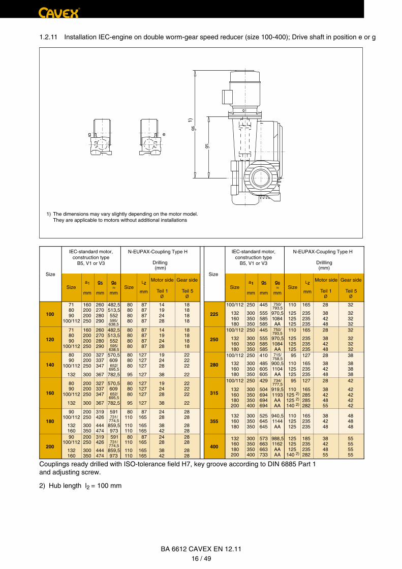
1.2.11 Installation IEC-engine on double worm-gear speed reducer (size 100-400); Drive shaft in position e or g
1)
1) The dimensions may vary slightly depending on the motor model. They are applicable to motors without additional installations
eg
Size
IEC-standard motor,construction type
B5, V1 or V3
IEC-standard motor,construction type
B5, V1 or V3
N-EUPAX-Coupling Type H
Drilling(mm)
Size
N-EUPAX-Coupling Type H
Drillling(mm)
Sizea1 g5 g6
SizeLZ
Motor side Gear side Motor side Gear side
Sizea1 g5 g6
SizeLZ
mm
g5
mm
g6≈
mm
Z
mm Teil 1Ø
Teil 5Ø
1
mm
g5
mm
g6≈
mm
Z
mm Teil 1Ø
Teil 5Ø
100
718090
100/112
160200200250
260270280290
482,5 513,5 552
595/638,5
80 80 80 80
87 87 87 87
14192428
18181818
225
100/112
132160180
250
300350350
445
555585585
750/793,5
970,51084AA
110
125125125
165
235235235
28
384248
32
323232
120
718090
100/112
160200200250
260270280290
482,5 513,5 552
595/638,5
80 80 80 80
87 87 87 87
14192428
18181818
250
100/112
132160180
250
300350350
445
555585585
750/793,5
970,51084AA
110
125125125
165
235235235
28
384248
32
323232
140
8090
100/112
132
200200250
300
327337347
367
570,5 609
652/695,5
782,5
570,5 609
652/695,5
782,5
80 80 80
95
127127127
127
192428
38
222222
22
280
100/112
132160180
250
300350350
410
485605605
715/758,5
900,51104AA
95
110125125
127
165235235
28
384248
38
383838
160
8090
100/112
132
200200250
300
327337347
367
80 80 80
95
127127127
127
192428
38
222222
22
315
100/112
132160180200
250
300350350400
429
504694694694
734/777,5
919,51193AAAA
95
110125 2)
125 2)
140 2)
127
165285285282
28
38424855
42
42424242
180
90100/112
132160
200250
300350
319426
444474
591731/
774,5
731/774,5
859,5973
80110
110110
87165
165165
2428
3842
2828
2828
355132160180
300350350
525645645
940,51144AA
110125125
165235235
384248
484848
200
90100/112
132160
200250
300350
319426
444474
591
859,5973
80110
110110
87165
165165
2428
3842
2828
2828
400
132160180200
300350350400
573663663733
988,51162AAAA
125125125
140 2)
185235235282
38424855
55555555
Couplings ready drilled with ISO-tolerance field H7, key groove according to DIN 6885 Part 1 and adjusting screw.
2) Hub length l2 = 100 mm
®
BA 6612 CAVEX EN 12.1116 / 49
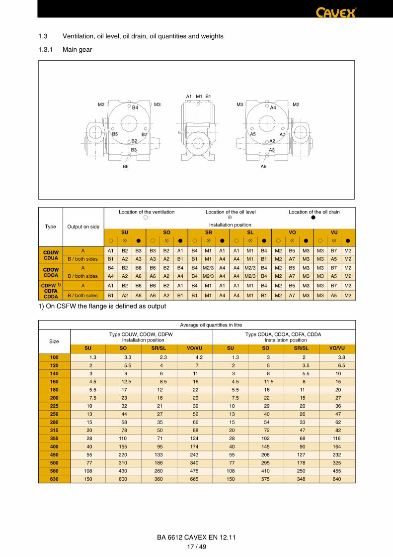
1.3 Ventilation, oil level, oil drain, oil quantities and weights
1.3.1 Main gear
M1A1 B1
M3 2M3M2MB4
B7B5
B6
B2
B3
A4
A7A5
A6
A2
A3
Location of the ventilation Location of the oil level �
Location of the oil drain
Type Output on side Installation position
SU SO SR SL VO VU
� � � � � �
CDUW A A1 B2 B3 B3 B2 A1 B4 M1 A1 A1 M1 B4 M2 B5 M3 M3 B7 M2CDUWCDUA B / both sides B1 A2 A3 A3 A2 B1 B1 M1 A4 A4 M1 B1 M2 A7 M3 M3 A5 M2
CDOW A B4 B2 B6 B6 B2 B4 B4 M2/3 A4 A4 M2/3 B4 M2 B5 M3 M3 B7 M2CDOWCDOA B / both sides A4 A2 A6 A6 A2 A4 B4 M2/3 A4 A4 M2/3 B4 M2 A7 M3 M3 A5 M2
CDFW 1)
CDFAA A1 B2 B6 B6 B2 A1 B4 M1 A1 A1 M1 B4 M2 B5 M3 M3 B7 M2
CDFACDDA B / both sides B1 A2 A6 A6 A2 B1 B1 M1 A4 A4 M1 B1 M2 A7 M3 M3 A5 M2
1) On CSFW the flange is defined as output
Average oil quantities in litre
Type CDUW, CDOW, CDFW Type CDUA, CDOA, CDFA, CDDAInstallation position Installation position Size
SU SO SR/SL VO/VU SU SO SR/SL VO/VU
100 1.3 3.3 2.3 4.2 1.3 3 2 3.8
120 2 5.5 4 7 2 5 3.5 6.5
140 3 9 6 11 3 8 5.5 10
160 4.5 12.5 8.5 16 4.5 11.5 8 15
180 5.5 17 12 22 5.5 16 11 20
200 7.5 23 16 29 7.5 22 15 27
225 10 32 21 39 10 29 20 36
250 13 44 27 52 13 40 26 47
280 15 58 35 66 15 54 33 62
315 20 78 50 88 20 72 47 82
355 28 110 71 124 28 102 68 116
400 40 155 95 174 40 145 90 164
450 55 220 133 243 55 208 127 232
500 77 310 186 340 77 295 178 325
560 108 430 260 475 108 410 250 455
630 150 600 360 665 150 575 348 640
®
BA 6612 CAVEX EN 12.1117 / 49

1.3.2 Primary gear
Size
X (mm)
180200
225250
280315
355400
60 70 82 95 110 135
450500
560630
160 190
100120
140160
Bei senkrechter Antriebswelle muß oberhalb des Getriebes beiM6 bzw. M7 ein Freiraum von der Höhe X vorgesehen werden.
M1A1 B1
M7B4
B7B2
B5
B6
6M7M6MA4
A7A2
A5
A6
Location of the ventilation Location of the oil level �
Location of the oil drain
an der VorschaltstufeDrive shaft in position Installation position
SU SO SR SL VO VU
� � � � � �
a A6 A2 B1 B1 A2 1) A6 M7 A5 M6 M6 A7 M7 A4 M1 B1 B1 M1 A4
b B6 B2 A1 A1 B2 1) B6 M6 B5 M7 M7 B7 M6 B4 M1 A1 A1 M1 B4
c A1 B2 1) B6 B6 B2 A1 M7 B7 M6 M6 B5 M7 B4 M1 A1 A1 M1 B4
d B1 A2 1) A6 A6 A2 B1 M6 A7 M7 M7 A5 M6 A4 M1 B1 B1 M1 A4
e M6 A7 M7 M7 A5 M6 A6 A2 B1 B1 A2 1) A6 A4 M1 B1 B1 M1 A4
f M7 B7 M6 M6 B5 M7 B6 B2 A1 A1 B2 1) B6 B4 M1 A1 A1 M1 B4
g M6 B5 M7 M7 B7 M6 A1 B2 1) B6 B6 B2 A1 B4 M1 A1 A1 M1 B4
h M7 A5 M6 M6 A7 M7 B1 A2 1) A6 A6 A2 B1 A4 M1 B1 B1 M1 A4
1) Sizes 100 - 160: B5 insread of B2 respectively A5 instead of A2
Durchschnittliche Ölmengen der Vorschaltstufe in LiterAverage weights of
gear and main stage without oil
Installation position Type
SizeSU SO SR SL VO / VU
CD W CD APosition of the drive shaft
CD.W
kg
CD.A
kga / b c / d e - h a / b c / d e - h a - d e / f g / h a - d e / f g / h a - h
kg kg
100 0.7 0.6 1 0.6 0.7 1 1 0.7 0.6 1 0.6 0.7 0.6 57 55
120 0.7 0.6 1 0.6 0.7 1 1 0.7 0.6 1 0.6 0.7 0.6 80 77
140 1.6 1.2 2 1.2 1.6 2 2 1.6 1.2 2 1.2 1.6 1.1 115 110
160 1.6 1.2 2 1.2 1.6 2 2 1.6 1.2 2 1.2 1.6 1.1 150 145
180 3 1.3 3.8 1.3 3 3.8 3.8 3 1.3 3.8 1.3 3 2 210 200
200 3 1.3 3.8 1.3 3 3.8 3.8 3 1.3 3.8 1.3 3 2 260 250
225 5 2 6.5 2 5 6.5 6.5 5 2 6.5 2 5 3.5 350 330
250 5 2 6.5 2 5 6.5 6.5 5 2 6.5 2 5 3.5 440 420
280 8 3 10 3 8 10 10 8 3 10 3 8 5.5 600 570
315 11.5 4.5 15 4.5 11.5 15 15 11.5 4.5 15 4.5 11.5 8 810 770
355 16 5.5 20 5.5 16 20 20 16 5.5 20 5.5 16 11 1180 1130
400 22 7.5 27 7.5 22 27 27 22 7.5 27 7.5 22 15 1600 1540
450 29 10 36 10 29 36 36 29 10 36 10 29 20 2240 2170
500 40 13 47 13 40 47 47 40 13 47 13 40 26 3040 2960
560 54 15 62 15 54 62 62 54 15 62 15 54 33 4170 4070
630 72 20 82 20 72 82 82 72 20 82 20 72 47 5630 5510
®
BA 6612 CAVEX EN 12.1118 / 49
Size 100 - 120 140 - 160 180 - 200 225 - 250 280 - 315 355 - 400 450 - 500 560 - 630
Model n11/min LpA dB(A)
3000 76 78 80 82 84
CD.. 1500 <70 <70 <70 <70 71 74 77 79
750 <70 <70 <70 <70 <70 <70 <70 <70
BA 6612 CAVEX EN 12.1119 / 49
®
1.4
Table 1.2: Measurement surfaces - Sound pressure level LpA in dB(A)
2. General information
2.1
2.2
Attention!
CAVEX GmbH & Co. KGTübinger Straße 2D-72131 Ofterdingen
Telephone: +49 (0) 7473 95 546-13Telefax: +49 (0) 7473 95 546-88
E-Mail: [email protected] Internet: www.CAVEX-GmbH.de
Measurement surfaces – Sound pressure level
The measurement surfaces – sound pressure level of the CAVEX® gear unit according to DIN 45635 is applicable on a measurement surface in 1 m distance from the gear surface with a minimum of 30% nominal capacity.
The measurement surfaces – sound pressure levels stated in Table 1.2 are taken from the quality control statistic evaluations. It can be expected that the CAVEX® gear unit does not exceed these noise levels. If no clear conditions can be created on site for technical measurement during remea-surements, the measurement on the CAVEX GmbH & Co. KG testing benches is applicable.
Introduction
The present instruction manual is included in the delivery of the gear unit and should always be kept close to the gear unit.
The CAVEX® gear unit described here is constructed according to the recognized safety-technical rules and corresponds to the technical status at the time this instruction manual was printed.
In the interest of further development we reserve the right to conduct those changes on the individual components and accessories that are deemed beneficial for the increase of performance and safety with the maintenance of the essential features.
Copyright
The copyright to this instruction manual remains with CAVEX GmbH & Co. KG.
The instruction manual may not be used in part or in whole without authorization and without our consent for competitive purposes or made available to third parties.
Please contact our factory in case of technical questions:
Every person who is involved in the assembly, operation, maintenance and repair of the gear unit must have read and understood the instruction manual, and adhere to it. We are not liable for damage and operational defects that occur due to non-adherence to the instruction manual.
or contact one of our customer service addresses. A list of our customer service offices is available on the website www.cavex-gmbh.de
®
3. Safety information
3.1
3.2
3.3 Environmental protection
The relevant regulations and guidelines, for example ISO 14001, as well as the laws of the countries and states shall be followed. This is particularly applicable to the usage of lubricants, preservation and cleaning agents. The regulations of the manufacturers of the operating materials, auxiliary mate-rials and tools being used must be followed.
Intended usage
The CAVEX® gear unit is constructed according to state-of-the-art technology and is delivered safe to operate. Unauthorized modifications, installations and modifications that influence the safety are not permitted. This also is applicable to safety installations that are installed as contact protection.
The CAVEX® gear unit may only be used and operated in the framework of the conditions defined on the delivery contract.
General obligations
• The operator is to ensure that all persons working on the assembly, operation, maintenance and service and repair of the device have read and understood the instruction manual, and that they adhere to all items, in order to:
– avoid danger to life and limb of the user and third parties
– ensure the operational safety of the gear unit
and
– exclude downtimes and environmental influences due to incorrect operation.
• The relevant occupational safety and environmental protection regulations shall be adhered to during transport, assembly and disassembly, operation and service and maintenance.
• The gear unit may only be operated, serviced and repaired by authorized, trained and instructed personnel.
• Cleaning the device with a pressure cleaning device is not permissible.
• All work shall be performed diligently and from the point of ”Safety“.
• It is mandatory to: Work on the gear unit may only be performed at rest. The drive unit must be secured against unintentional start up. A sign indicating “work is in progress” on the gear unit must be applied to the activating switch of the gear unit.
• Welding work must not be performed on the gear unit. The gear units must not be used as ground point for welding work. Gear parts and bearings could be destroyed by welding.
• The drive aggregate must be switched off immediately if changes to the device are perceived during operation, such as for example an increased operating temperature or change of gear noises.
• Openly rotating drive parts must be secured against contact using appropriate safety measures.
• When installing the CAVEX® gear unit in devices or units, the manufacturer of the devices or units is obligated to incorporate into his instruction manual the regulations, information and descriptions contained within this instruction manual.
• Information markings affixed to the CAVEX® gear unit, such as for example the type plate, turning direction arrow etc. must be observed. They must be free from paint and dirt. Missing information plates must be replaced.
Non-standard spare parts, such as bearings, radial shaft sealing rings, seals, screws, nuts, washers, sealing plugs, ventilation screws, oil level displays must always be obtained from CAVEX GmbH & Co. KG.
BA 6612 CAVEX EN 12.1120 / 49

3.4 Special dangers
3.5 Warnings and symbols in this instruction manual
Information:
4. Transport and storage
Information: Follow the instructions in Chapter 3. ”Safety instructions”.
4.1 Scope of delivery
4.2 Transport
image-transport
this side up fragile goods
protect from moisture
protectfrom heat
centre of gravity No hooks fasten well
Attention!
Attention!
®
The transport of the gear unit must be conducted with adequate care to avoid personal injury and damage to the gear unit. For example, impacts on free shaft ends may lead to damage in the gear unit.
To transport the gear unit, appropriate fastening means (for example eyebolts) must be screwed into the prepared threads on the top of the casing. The front threads in the shaft ends may not be used to attach eyebolts for transport.
For transport, only use hoisting devices and load lifting installations with suffi-cient carrying capacity!
Depending on the transport method and size the CAVEX® gear unit is packaged differently. If not specifically agreed upon differently by contract, the packaging corresponds to the HPE packaging guidelines. The image instructions on the package shall be followed:
The delivery content is listed in the shipping documents. Check that the delivery is complete upon receipt. Possible transport damage and/or missing parts must be reported in writing immediately.
• Depending on the operating condition, the CAVEX® gear unit may generate high surface tempera-tures. Risk of burns!
• When changing the oil there is the risk of burns resulting from the escaping hot oil.
This symbol indicates the safety measures that need to be followed to avoid perso-nal injury.
This symbol indicates safety measures that need to be followed to avoid damage to the gear unit.
This symbol indicates general operating instructions that need to be followed.
BA 6612 CAVEX EN 12.1121 / 49

®
4.3 Storage of the gear unit
4.4 Standard corrosion protection
4.5 Type plate
Attention!
The type plate is made of aluminium. The data according to Point 1.1 is engraved into the anodized surface for permanent legibility. The type plate is riveted onto the gear unit casing.
The gear unit must be stored in a weather-protected location on a vibration-free surface.
Stacking gear units on top of each other is not permissible.
When storing a gear unit outside, the unit must be covered carefully. It must be ensured that moisture or dirt cannot settle onto the gear unit.
The shaft ends, the drilling of the hollow shaft and the installation surface of the output flange are prepared with corrosion protection. It is seawater resistant and tropic-proof for a period of up to 12 months.
All the greasing points are greased with the appropriate agents.
The interior gear parts are corrosion protected. This protection is sufficient for normal transport conditions and a period of 6 months up to first start up.
In case of longer intermediate storages (> 6 months) the interior and exterior corrosion protection must be inspected and renewed, if necessary. The gear unit is delivered without oil.
BA 6612 CAVEX EN 12.1122 / 49
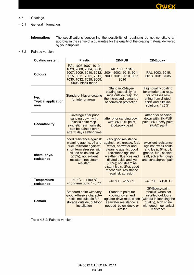
4.6. Coatings
4.6.1 General information
Information:
4.6.2 Painted version
Coating system Plastic 2K-PUR 2K-Epoxy
Colours
typ.Typical applicationarea
Standard-1-layer-coatingfor interior areas
Standard-2-layer-coating especially for
usage outside resp. for the increased demands of corrosion protection
High quality coatingfor exterior use resp.
for stresses res-ulting from diluted acids and alkaline solutions ( ≤5%)
Recoatability
chem. phys.resistance
Temperature resistance
Remark
Table 4.6.2: Painted version
®
The specifications concerning the possibility of repainting do not constitute an approval in the sense of a guarantee for the quality of the coating material delivered by your supplier.
RAL 1003,1007, 1012,1023, 2000, 2004, 3000,5007, 5009, 5010, 5012,5015, 6011, 7001, 7011,7030, 7032, 7035, 9005,
9006, black-matte
RAL 1003, 1018, 2004, 5002, 5015, 6011, 7000, 7031, 9010, 9011,
9016
RAL 1003, 5015,6018, 7031, 7035
2K-Epoxy-paint “chalks” when set installed outdoors
(without influencing the quality), high shine
with good mechanical resistance
excellent resistance against: weak acids and lye (≤ 5%), oil,
grease, fuel, coolant, salt, solvents; tough
and scratchproof paint
very good resistance against: oil, grease, fuel,
water, seawater and cleaning agents; good
resistance against: weather influences and
diluted acids and lye (≤ 3%); not steam re-
sistant lye (≤ 3%); good mechanical resistance
against: abrasion
after prior sanding down with: 2K-PUR paint,
2K-Epoxy paint
after prior sanding down with: 2K-PUR
paint, 2K-Epoxy paint, 2K-AC paint
Coverage after prior sanding down with: plastic paint resp.
synthetic resin varnish; can be painted over
after 3 days setting time
good resistance against: cleaning agents, oil and fuel; resistant against:
short term stresses with diluted acids and lye(≤ 3%); not solvent resistant; not steam
resistant
Standard paint for cooling tower and
agitator drive resp. when seawater resistance is needed below deck, or
similar
Standard paint with very good adhesive characte-
ristic, not suitable for: storage outside, outdoor
installation
–40 °C ... +100 °Cshort-term up to 140 °C
–40 °C ... +150 °C –40 °C ... +150 °C
BA 6612 CAVEX EN 12.1123 / 49
®
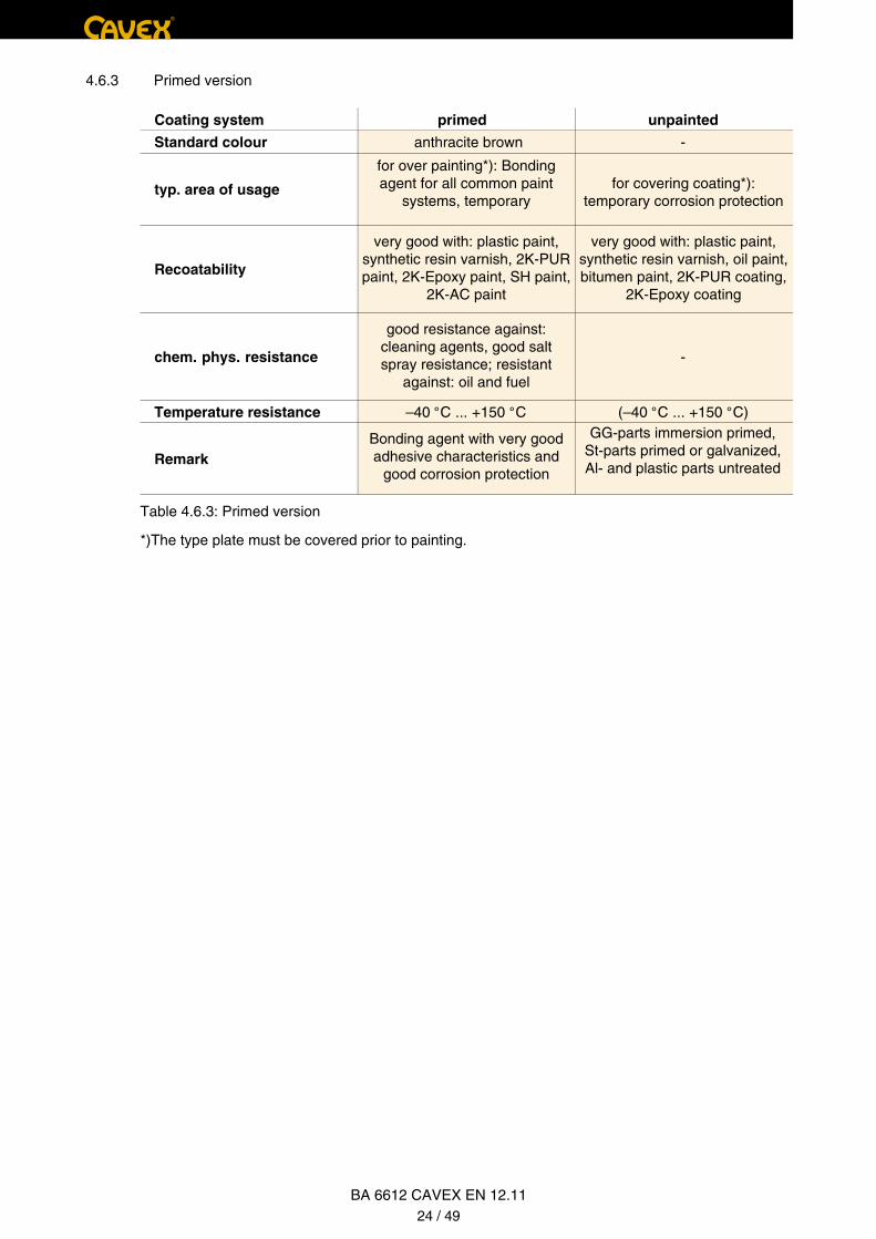
4.6.3 Primed version
primedCoating system unpainted
Standard colour anthracite brown -
typ. area of usage
Recoatability
chem. phys. resistance -
Temperature resistance –40 °C ... +150 °C (–40 °C ... +150 °C)
Remark
Table 4.6.3: Primed version
*)The type plate must be covered prior to painting.
for over painting*): Bonding agent for all common paint
systems, temporary
very good with: plastic paint, synthetic resin varnish, 2K-PUR paint, 2K-Epoxy paint, SH paint,
2K-AC paint
good resistance against: cleaning agents, good salt spray resistance; resistant
against: oil and fuel
Bonding agent with very good adhesive characteristics and
good corrosion protection
GG-parts immersion primed, St-parts primed or galvanized, Al- and plastic parts untreated
very good with: plastic paint, synthetic resin varnish, oil paint, bitumen paint, 2K-PUR coating,
2K-Epoxy coating
for covering coating*):temporary corrosion protection
BA 6612 CAVEX EN 12.1124 / 49
5. Technical description
5.1 General information
Information: Follow the instructions in Chapter 3. ”Safety instructions”.
5.2 Identification
Colour identification of ventilation, oil level and oil drainage:
Ventilation and oil input:
Oil level and lubrication positions:
Oil drainage:
®
The gear is a two-level gear with a primary gear as worm gear with CAVEX® toothing and a main gear as worm-gear speed reducer with CAVEX® toothing.
yellow
red
white
5.3 Ventilator
5.4 Couplings
5.5 Shrink disc
5.6 Backstop
For certain requirements the gear unit is equipped with a mechanical backstop.
Information:
Attention!
On worm gear units equipped with ventilators, the ventilator is arranged on the fast running worm shaft of the gear unit and secured against unintentional contact by a ventilator cover. The ventilator sucks in air through the protective grid of the ventilator cover and leads it past the gear casing through the lateral air channels. This cools the air surrounding the gear casing.
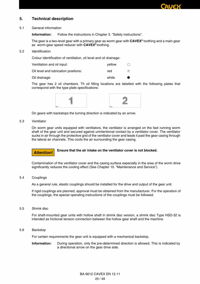
The gear has 2 oil chambers. Th oil filling locations are labelled with the following plates that correspond with the type plate specifications:
On gears with backstops the turning direction is indicated by an arrow.
Contamination of the ventilator cover and the casing surface especially in the area of the worm drive significantly reduces the cooling effect (See Chapter 10. “Maintenance and Service”).
As a general rule, elastic couplings should be installed for the drive and output of the gear unit.
If rigid couplings are planned, approval must be obtained from the manufacturer. For the operation of the couplings, the special operating instructions of the couplings must be followed.
For shaft-mounted gear units with hollow shaft in shrink disc version, a shrink disc Type HSD-32 is intended as frictional tension connection between the hollow gear shaft and the machine.
Ensure that the air intake on the ventilator cover is not blocked.
During operation, only the pre-determined direction is allowed. This is indicated by a directional arrow on the gear drive side.
BA 6612 CAVEX EN 12.1125 / 49
®
Information:
Version B:
5.7 Assembly of IEC-Motors
When installing IEC-Motors, pay attention to the instruction manual of the motor.
6. Assembly
6.1 General assembly information
Information: Follow the instructions in Chapter 3. „Safety information“.
6.2. Description of the assembly
Attention!
Attention!
When using cleaning agents the relevant regulations and guidelines, for example according to ISO 14001, as well as the laws of the countries and states must be followed. Adhere to the regulations of the manufacturer of the cleaning agents.
Agreement with CAVEX GmbH & Co. KG is necessary to change the rotation direction later on, as this is only possible with high level of technical effort.
In order to avoid damage or destruction of the backstop, attention must be paid to ensure that the motor is not driven against the locked backstop!
Any motor must not be used that exceeds the determined rotation speeds of the gear unit, as this may damage the gear unit.
This version is intended if a later change of rotation direction is expected and no ventilator is required for the gear unit.
The backstop is not integrated in the oil circuit. Separate lubrication is not necessary.
The assembly must be performed such that the gear unit is not distorted during assembly and operation.
The possibility of checking the oil level must be ensured.
Foundations and connection constructions must be made such that no vibrations are transferred from neighbouring components and parts.
A careful alignment to the output and drive side machine must be ensured, so that if necessary, elastic distortions due to the operating forces are taken into consideration if necessary.
Fixing screws or nuts must be tightened with the determined torque. The tightening torque is listed in relevant tables. Screws with the minimum strength class 8.8 shall be used.
If exterior forces influence the gear unit it is useful to prevent dislocation by lateral fixings.
The cooling of the CAVEX® gear units must not be influenced. Pay attention to free convection and open air flow during ventilator operation.
To guarantee sufficient lubrication during operation, the installation position stated in the order placement must be adhered to.
• Remove corrosion protection paint on the shaft ends and connecting surfaces with cleaning agents.
Differentiation is made between two versions:
Version A:
The backstop is installed in the lid on the ventilator side. The backstop is installed oil-proof over an intermediate flange on the gear unit and is integrated in its oil circuit.
BA 6612 CAVEX EN 12.1126 / 49

Protect against burning by hot parts!
Please follow the instruction manual of the part to be assembled.
6.3 Assembly of a shaft-mounted gear with fitted key
6.3.1 Preparation
1
1 Pressurized oil connection
Information:
Attention!
Attention!
Attention!
Attention!
®
• Mount couplings and similar connecting parts onto the shaft ends and secure them. If they are to be mounted warm, the necessary joining temperatures shall be requested from the manufacturer of the parts to be mounted.
Warming can be performed, if not described otherwise, by induction, with a burner or in the oven.
The gear shaft ends have thread drillings at the front ends with which couplings, disc, gears or similar can be mounted.
For better disassembly we recommend installing a connection for pressurized oil at the shaft end of the machine. To do this, provide a drilled hole that ends at the turned end of the hollow shaft.
The shaft end of the machine must be equipped with a fitted key according to DIN 6885 part 1 Form A and should have a centring device according to DIN 332 Form DS (with thread) on the front end.
The parts to be mounted shall be assembled with help of suitable equipment to prevent damage of the shaft bearing due to axial joining force. The usage of appropriate hoisting devices must be ensured. Ensure that the shaft sealing rings and the surface of the shaft are not dama-ged when mounting the elements.
Any fitting by impact or force is not permissible, as this may damage the rolling bearing, sealing rings and similar parts.
Cleaning agents must not be allowed to penetrate beneath the sealing lips of the shaft sealing rings.
Protection of the cleaned contact surfaces with an appropriate lubricant that prevents fretting corrosion.
Check the hollow and machine shaft for damage to the intakes or edges. If necessary, refinish parts with an appropriate tool and clean them again.
Attention!
BA 6612 CAVEX EN 12.1127 / 49

®
6.3.2 Assembly
Information:
1
2
3
4
4
3
2
3142
6.4 Assembly of a shaft-mounted gear unit with shrink disc
6.4.1 Preparation
Please follow the instruction manual of the part to be assembled.
6.4.2 Mounting
Attention!
Attention!
Attention!
Attention!
Attention!
Attention!
Assembly of the hollow shaft gear unit onto the machine shaft can be performed with an end disc and securing ring, insofar these parts were included in the delivery.
Cover plate End plate (Dismounting disc)
Screw Securing ring
By turning the end plate and using an appropriate screw, the end plate can be used as dismounting disc.
When using cleaning agents, adhere to the relevant regulations and guide-lines, for example according to ISO 14001, as well as the laws of the countries and states. Follow the regulations of the manufacturer of the cleaning agent.
Cleaning agents must not be allowed to penetrate beneath the sealing lips of the shaft sealing rings.
Any lifting by impact or force is not permissible, as this can damage the rolling bearings, securing rings and similar parts.
The hollow shaft may only be drawn against a machine shaft collar on models with torque support, as the bearings would be distorted on other models.
The hollow shaft must be aligned with the machine shaft, so that jamming is prevented.
• Remove the corrosion protection coating on the shaft ends and connecting surfaces with a cleaning agent.
• Mounting with installed slide bush
• Mount drive with nut and threaded spindle. Support is given by the hollow shaft.
The drilling of the hollow shaft and the exterior diameter of the machine shaft must be thoroughly cleaned in the area of the shrink disc position. Both surfaces must be absolutely free of grease.The safety of the torque transfer is highly dependant on this. Contaminated cleaning agents and cloths are inappropriate for degreasing the surfaces.
BA 6612 CAVEX EN 12.1128 / 49

4321 56
Machine shaftHollow shaft Hexagon nut
Threaded spindle DiscSlide bush
123
456
machine shaft hollow shaft interior ring
exterior ring tensioning screw
123
45
Information: Parts 3, 4 and 5 are not included in the scope of delivery.
6.4.3 Axial securing
6.4.4 Assembly of the shrink disc
The shrink disc is delivered ready to install.
It may not be disassembled prior to first tensioning.
4
1
2
3
5
A
B
A greased B absolutely free of grease
Attention!
Attention!
Attention!
®
The hollow shaft must be aligned with the machine shaft, so that jamming is prevented.
On flange gear units, the hollow shaft may not be axially and radically distorted, as the bearings may fail due to excessive load.
Instead of the shown nut and threaded spindle you may also use a hydraulic puller.
The axial securing of the hollow shaft on the machine shaft is performed by the shrink disc connection.
BA 6612 CAVEX EN 12.1129 / 49
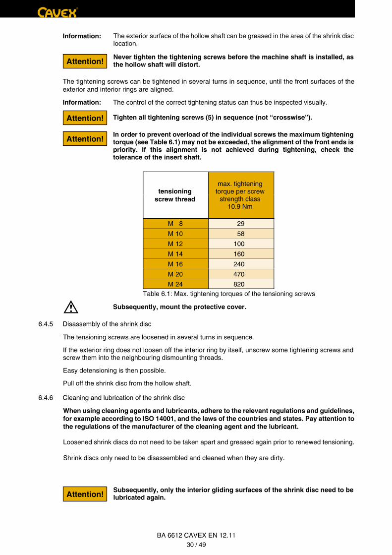
®
Information:
Information: The control of the correct tightening status can thus be inspected visually.
Tighten all tightening screws (5) in sequence (not “crosswise”).
tensioningscrew thread
M 8 29
M 10 58
M 12 100
M 14 160
M 16 240
M 20 470
M 24 820Table 6.1: Max. tightening torques of the tensioning screws
Subsequently, mount the protective cover.
6.4.5 Disassembly of the shrink disc
6.4.6 Cleaning and lubrication of the shrink disc
Attention!
Attention!
Attention!
Attention!
max. tightening torque per screw
strength class 10.9 Nm
Subsequently, only the interior gliding surfaces of the shrink disc need to be lubricated again.
When using cleaning agents and lubricants, adhere to the relevant regulations and guidelines, for example according to ISO 14001, and the laws of the countries and states. Pay attention to the regulations of the manufacturer of the cleaning agent and the lubricant.
Loosened shrink discs do not need to be taken apart and greased again prior to renewed tensioning.
Shrink discs only need to be disassembled and cleaned when they are dirty.
The exterior surface of the hollow shaft can be greased in the area of the shrink disc location.
Never tighten the tightening screws before the machine shaft is installed, as the hollow shaft will distort.
In order to prevent overload of the individual screws the maximum tightening torque (see Table 6.1) may not be exceeded, the alignment of the front ends is priority. If this alignment is not achieved during tightening, check the tolerance of the insert shaft.
The tightening screws can be tightened in several turns in sequence, until the front surfaces of the exterior and interior rings are aligned.
The tensioning screws are loosened in several turns in sequence.
If the exterior ring does not loosen off the interior ring by itself, unscrew some tightening screws and screw them into the neighbouring dismounting threads.
Easy detensioning is then possible.
Pull off the shrink disc from the hollow shaft.
BA 6612 CAVEX EN 12.1130 / 49
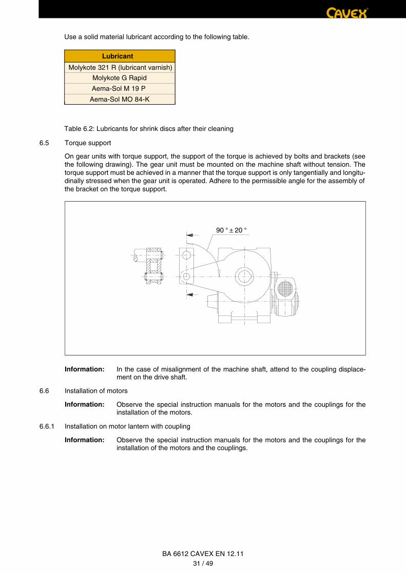
6.5 Torque support
Information:
6.6 Installation of motors
Information:
6.6.1 Installation on motor lantern with coupling
Information:
Use a solid material lubricant according to the following table.
Lubricant
Molykote 321 R (lubricant varnish)
Molykote G Rapid
Aema-Sol M 19 P
Aema-Sol MO 84-K
Table 6.2: Lubricants for shrink discs after their cleaning
On gear units with torque support, the support of the torque is achieved by bolts and brackets (see the following drawing). The gear unit must be mounted on the machine shaft without tension. The torque support must be achieved in a manner that the torque support is only tangentially and longitu-dinally stressed when the gear unit is operated. Adhere to the permissible angle for the assembly of the bracket on the torque support.
In the case of misalignment of the machine shaft, attend to the coupling displace-ment on the drive shaft.
Observe the special instruction manuals for the motors and the couplings for the installation of the motors and the couplings.
Observe the special instruction manuals for the motors and the couplings for the installation of the motors.
®
BA 6612 CAVEX EN 12.1131 / 49
90 ° ± 20 °
®
7. Start up
Information: Follow the instructions in Chapter 3. ”Safety instructions”.
7.1 Oil filling
Attention!
Attention!
Gear will be supplied without oil filling. Before initial operation, anti-corrosion agent must be discharged and gear must be filled with oil.
When using cleaning agents and lubricants, adhere to the relevant regulations and guidelines, for example according to ISO 14001, as well as the laws of the countries and states. Follow the instructions of the manufacturer of the cleaning agent and lubricants.
Prior to start up, check the oil level. The oil must be filled at least to the middle of the oil level window, as a maximum to the upper edge of the oil level window or up to the lower edge of the oil level opening. The upper locking screw must be replaced with the included ventilation screw.
The oil viscosity to be maintained is listed on the rating plate of every gear unit. If other oils must be used, it is more permissible to use thicker oils than thinner oils. The only oils permissible for use are those listed in the lubricant table in Chapter 10, or according to the lubricant table on the website of CAVEX GmbH & Co. KG.
7.2 Lubrication of bearings
Bearings located above the oil level are equipped with grease filling.
7.3 Installation and assembly parts
7.3.1 Gear units with backstop
Installed or assembled backstops are automatically lubricated.
Attention!In order to avoid damage or destruction of the backstop, ensure that the motor is not driven in the locking direction of the backstop!
Prior to start up, check whether the backstop can be turned in freewheeling without increased effort. The rotational direction arrows on the gear units must be adhered to.
For CAVEX® gear units with special additional installations (e.g. pumps, filter-oil cooler, spring-applied brakes, multi-disc clutch or similar) the specific operating instructions must be followed.
The oil quantity stated on the type plate is a reference value. When filling the oil, wait until the oil has become evenly distributed and thus the final oil level is displayed.
BA 6612 CAVEX EN 12.1132 / 49
®
7.4 Electrical connection (on CAVEX® gear units with assembled motor)
7.5 Start Up
8. Operation
Information: Follow the instructions in Chapter 3. ”Safety instructions”.
Attention!If irregularities occur during operation, the cause must be determined using the fault table (see Chapter 9.). The fault table contains possible faults, their causes and suggestions for solutions. If the cause cannot be determined resp. if it is not possible to repair the unit with own means, we recommend contacting CAVEX GmbH & Co. KG.
Work on the terminals and live parts may generally only be performed by specially trained personnel. Follow the safety instructions.
During operation, check the CAVEX® gear unit for:
• high operating temperature
• different gear unit sounds
• possible oil leaks
During start up, ensure that the ventilation screw with cap is installed; if necessary, remove the plastic screw cap or lock screw.
Subsequently, the gear unit is to be operated initially in intermittent duty, meaning operated under normal operating stress for a few minutes, alternating with breaks lasting several times the length of the operating duration. The active periods can be gradually increased up to normal operation, where-by the operating temperature needs to be monitored. Operating temperatures of up to approx. +100°C are permissible.
We include a circuit diagram in the terminal box of every E-Motor showing how the motor must be connected. When connecting, ensure that the system voltage corresponds to that stated on the rating plate.
In general, usage of a motor protection switch is recommended for protection against overload or phase failure. The overcurrent relay must be set to the correct rated input current assigned to the respective nominal voltage (see rating plate). Ground or protective wires must be connected with the included ground terminal.
If the motor runs in the wrong rotation direction, 2 phases of the mains connection must be swapped over.
BA 6612 CAVEX EN 12.1133 / 49
®
9. Faults, causes and solution
Information: Follow the instructions in Chapter 3. ”Safety instructions”.
9.1 General fault information
Information:
9.2 Possible defects
Defects Causes Solution
Different gear unit noises
Increased operating temperature Oil filling with non-approved oil
Oil level in the gear casing too high or too low
Oil is old
Oil is very contaminated
Suction opening of the ventilation cover and/or gear unit casingseverely contaminated
Grease filling of the bearings is old
Bearing defective
Backstop does not move freely
Oil leak Radial-shaft sealing rings defective Change radial-shaft sealing rings
Table 9.1: Fault information
Defects that occur during the warranty period and require repair of the gear unit may only be remedied by the CAVEX GmbH & Co. KG customer service. We also recommend using our customer service after the expiry of the warranty term.
In general, the gear unit must be turned off during the repair of defects. Secure the drive aggregate against unintentional start up. Attach an informa-tion sign to the activation switch.
Bearing tolerance enlarged
Bearing defective
Damage to the gears
Gear unit mounting is loose
Contact customer service.
Contact customer service.
Contact customer service.
Tighten screws / nuts with prescribed torque.
Replace damages screws / nuts.
Fill with permissible oil
Check oil level at room temperatureif necessary correct oil level
Change oil. See Chapter 10.
Change oil. See Chapter 10.
Clean ventilator cover and gear unit casing
New lubrication.See Chapter 10.
Contact customer service.
Contact customer service.
BA 6612 CAVEX EN 12.1134 / 49
®
10. Maintenance and service
Information: Follow the instructions in Chapter 3. ”Safety instructions”.
10.1 General maintenance specifications
Information:
Measures Deadlines Remarks
Monitor oil temperature, gear unitsounds and tightness
Check oil level
First oil change
Further oil changes
Lubrication of the bearing
Renew grease in the bearings
Clean ventilation screw
Clean ventilator and casing
Check fixing screws for tightness
continuously
every 3 months
after approx. 1000-2000 operating hours
after approx. 6000-12000 operating hours, at the latest after 5 years
see plates with exact instructions for the grease nipple
after approx. 10000 to 15000 operating hours, at the latest after 5 years
if contaminated
if contaminated
during every oil change
in case of change see Table 9.1
see Items 7.1. and 10.2.1
see Items 7.1. and 10.2.1
see Item 10.2.2
see Item 10.2.2
see Item 10.2.3
see Item 10.2.4
Table 10.1: Maintenance intervals
All maintenance and service work shall be performed carefully and only by specially trained personnel.
The adherence to the warranty conditions also includes the adherence to the inspection intervals.
Oil level at least up to the middleof oil level window, maximum to the upper edge of the oil window or to the lower edge of the oil level opening for a cold gear unit in standstill
BA 6612 CAVEX EN 12.1135 / 49
10.2 Description of the maintenance and service work
When using cleaning agents and lubricants, adhere to the relevant regula-tons and guidelines, for example according to ISO 14001, and the laws of the countries and states. Follow the instructions of the manufacturer of the clea-ning agents and lubricants.
10.2.1 Oil change
Secure the drive aggregate against unintentional start up. Attach an informa-tion plate to the on-off switch.
Burning hazard due to hot oil. Before performing any work, wait until the oil has cooled to below +30 °C.
Remove excess oil immediately in an environmentally friendly manner using oil binding agents.
The oil quantity and the location of the lock elements depend on the installati-on position, see Item 1.3 “Ventilation, oil level, oil drainage, oil quantities and weights”.
During an oil change, the gear unit should be filled with the previously used oil. Mixing oils of different types is not permissible. Only use lubricants according to the lubricant table in Chapter 10 or according to the lubricant table on the website of CAVEX GmbH & Co. KG.
The oil must be drained immediately after the device was turned off, while the oil is still warm. The oil must be able to drain long enough to remove sludge, abrasion and remaining oil. Shimmering bronze abrasion in the oil is not harmful.
In case of double gear units, inspect each unit separately.
Surrounding conditions that deviate from the normal surrounding conditions (high surrounding temperatures, high humidity, aggressive surrounding media) shorten the change intervals. In this case, please contact CAVEX GmbH & Co. KG to determine individual intervals for lubricants change.
®
Information:
Information:
Information:
Attention!
Attention!
BA 6612 CAVEX EN 12.1136 / 49

10.2.2 Grease
The permissible roller bearing greases are listed in the lubricants table Chapter 10 and in the lubricants table on the website CAVEX GmbH & Co. KG.
When lubricating, do not mix greases of different soaps.
10.2.3 Clean ventilator and casing
• Shut down the gear unit by switching off the drive aggregate and secure it against rotation.
Secure the drive aggregate against unintentional start up. Attach informati-on plate to the activation location
• Remove possible corrosion, if present.
Cleaning with a pressure cleaning device is not permissible.
10.2.4 Check fixing screws for tightness
• Shut down the gear unit by switching off the drive aggregate and secure it against rotation.
Secure the drive aggregate against unintentional start up. Attach an informa-tion plate to the on-off switch.
Check all fixing screws for tightness and tighten if necessary. The tightening torques for the tightening screws are listed in the relevant tables.
Screws that can no longer be used must be replaced with new screws of the same strength class and design.
10.3 Lubrication
The oil of the different lubricants is listed in the following table. Our homepage at www.cavex-gmbh.com always shows you the newest specifications about all lubricants allowed by CAVEX GmbH & Co. KG.
If you decide not to follow our recommendation due to a reason that is important to you, you assume responsibility for the technical adequacy of the lubricant.
Therefore, we recommend that our customers select a lubricant from the table with consideration of the VG-class stated on the type plate.
Using gear oils that do not correspond to the above stated quality requirements may void our warranty obligation. We explicitly state that every oil manufacturer resp. oil supplier is responsible for the quality of his product.
The oil viscosity class stated on the rated plate of the gear unit is always decisive for the oil selection. When using a different viscosity or a different gear oil than recommended here the operator assumes responsibility for the technical adequacy of the lubricant.
Follow the instructions on the type plates and in the instruction manuals of the gear units!
Information:
Information:
Attention!
Attention!
Attention!
Attention!
®
BA 6612 CAVEX EN 12.1137 / 49
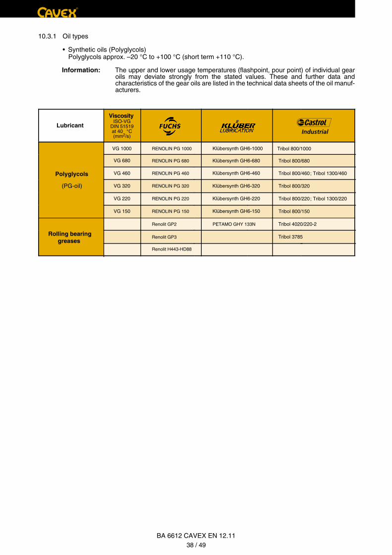
®
Lubricant
Viscosity ISO-VG
DIN 51519at 40 °C(mm2/s)
VG 1000
VG 680
Polyglycols VG 460
(PG-oil) VG 320
VG 220
VG 150
RENOLIN PG 1000
RENOLIN PG 680
RENOLIN PG 460
RENOLIN PG 320
RENOLIN PG 220
RENOLIN PG 150
Renolit GP2 PETAMO GHY 133N Tribol 4020/220-2
Tribol 3785Renolit GP3
Renolit H443-HD88
Rolling bearing greases
Klübersynth GH6-1000
Klübersynth GH6-680
Klübersynth GH6-460
Klübersynth GH6-320
Klübersynth GH6-220
Klübersynth GH6-150
Tribol 800/1000
Tribol 800/680
Tribol 800/460; Tribol 1300/460
Tribol 800/320
Tribol 800/220; Tribol 1300/220
Tribol 800/150
10.3.1 Oil types
• Synthetic oils (Polyglycols) Polyglycols approx. –20 °C to +100 °C (short term +110 °C).
Information: The upper and lower usage temperatures (flashpoint, pour point) of individual gear oils may deviate strongly from the stated values. These and further data and characteristics of the gear oils are listed in the technical data sheets of the oil manuf-acturers.
BA 6612 CAVEX EN 12.1138 / 49
®
11. Spare parts
11.1 Spare part storage
To order spare parts, please use the spare parts list and spare parts drawing.
We only provide a warranty for original spare parts that we deliver.
We explicitly state that spare parts we did not supply are also not inspected and approved by us. The installation and/or usage of such products may negatively alter constructively determined characteristics of the CAVEX® -gear unit and thus impede the active and/or passive safety. Any liability and warranty by CAVEX GmbH & Co. KG are excluded for damage occurring due to the usage of non-original-spare parts.
The following data shall be stated in spare part orders:
Ident-No. of the gear unit (see type plate)
Part-No. (from spare part list)
Quantity (from spare part list)
Attention!
BA 6612 CAVEX EN 12.1139 / 49
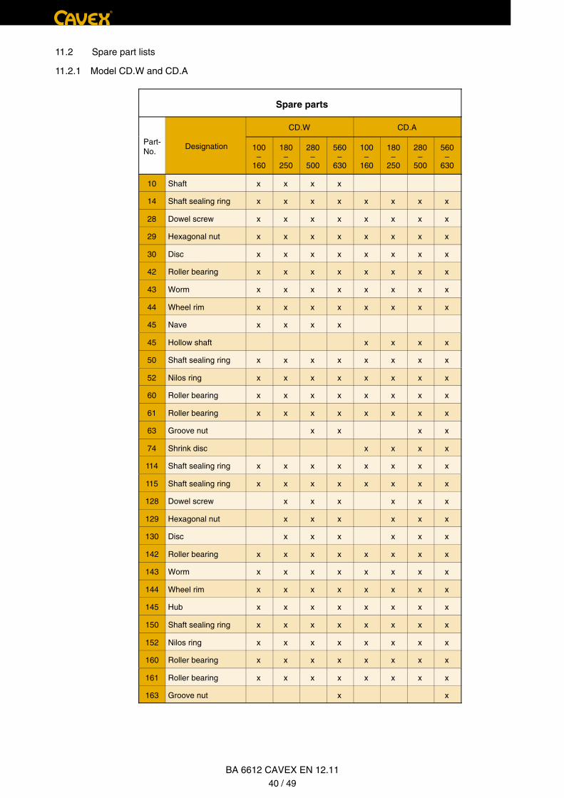
Spare parts
CD.W CD.A
Part-No.
Designation 100–
160
180–
250
280–
500
560–
630
100–
160
180–
250
280–
500
560–
630
10 Shaft x x x x
14 Shaft sealing ring x x x x x x x x
28 Dowel screw x x x x x x x x
29 Hexagonal nut x x x x x x x x
30 Disc x x x x x x x x
42 Roller bearing x x x x x x x x
43 Worm x x x x x x x x
44 Wheel rim x x x x x x x x
45 Nave x x x x
45 Hollow shaft x x x x
50 Shaft sealing ring x x x x x x x x
52 Nilos ring x x x x x x x x
60 Roller bearing x x x x x x x x
61 Roller bearing x x x x x x x x
63 Groove nut x x x x
74 Shrink disc x x x x
114 Shaft sealing ring x x x x x x x x
115 Shaft sealing ring x x x x x x x x
128 Dowel screw x x x x x x
129 Hexagonal nut x x x x x x
130 Disc x x x x x x
142 Roller bearing x x x x x x x x
143 Worm x x x x x x x x
144 Wheel rim x x x x x x x x
145 Hub x x x x x x x x
150 Shaft sealing ring x x x x x x x x
152 Nilos ring x x x x x x x x
160 Roller bearing x x x x x x x x
161 Roller bearing x x x x x x x x
163 Groove nut x x
®
BA 6612 CAVEX EN 12.1140 / 49
11.2 Spare part lists
11.2.1 Model CD.W and CD.A
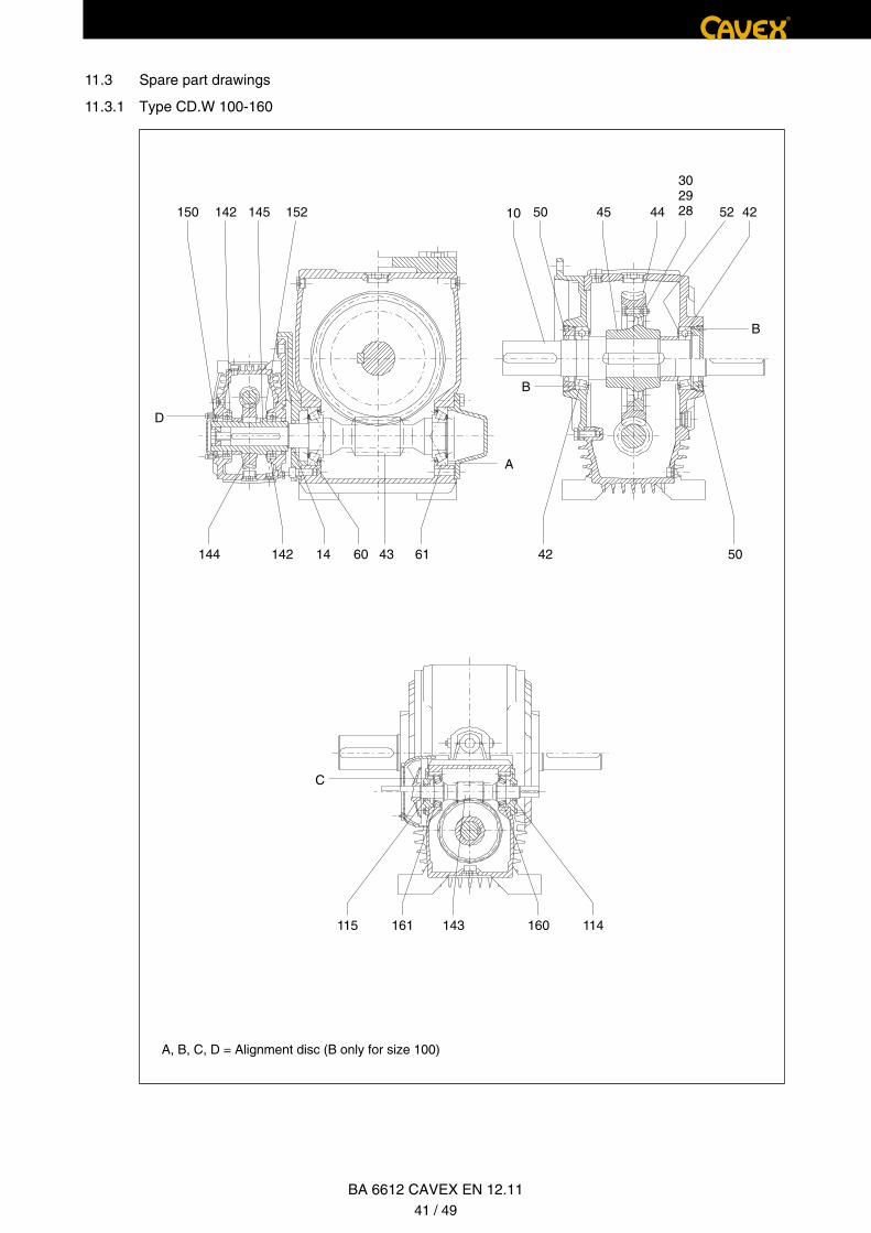
A, B, C, D = Alignment disc (B only for size 100)
142 524450150 45
D
A
42
302928
B
B
145 152 10
143161115
C
160 114
50614314142144 4260
®
BA 6612 CAVEX EN 12.1141 / 49
11.3 Spare part drawings
11.3.1 Type CD.W 100-160
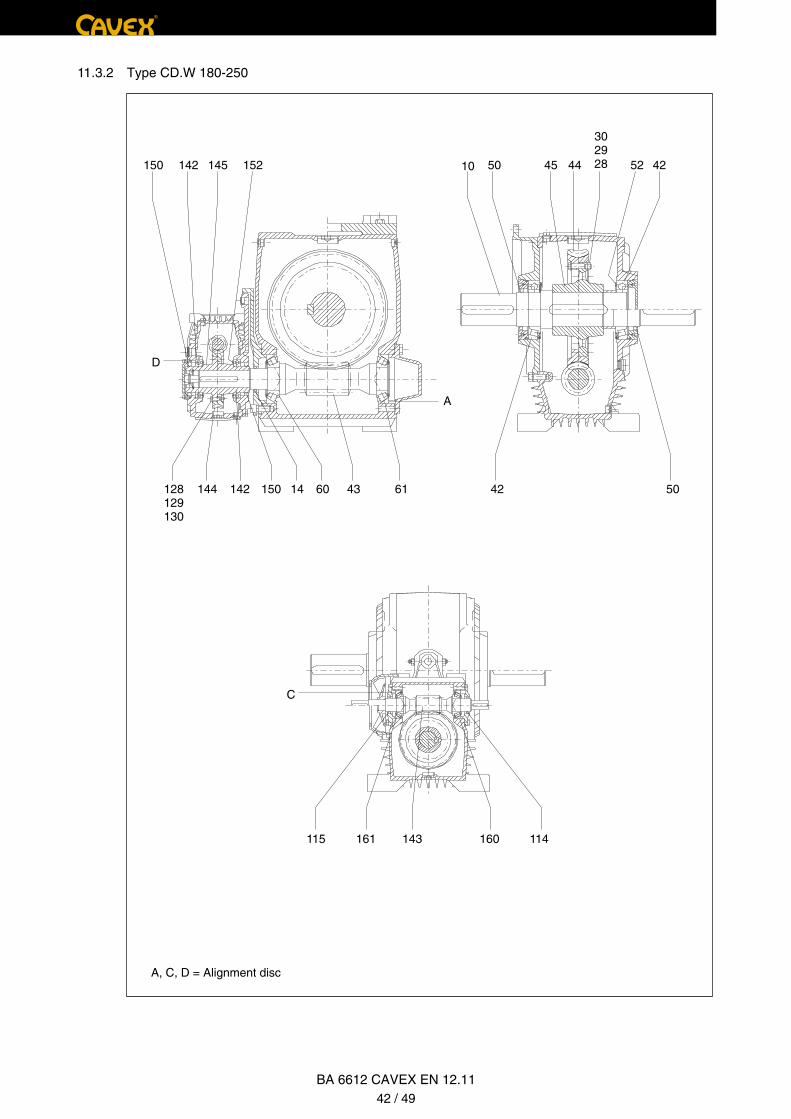
A, C, D = Alignment disc
142 524450150 45
D
A
42
302928145 152 10
143161115
C
160 114
50614314142144 4260150128129130
11.3.2 Type CD.W 180-250
®
BA 6612 CAVEX EN 12.1142 / 49
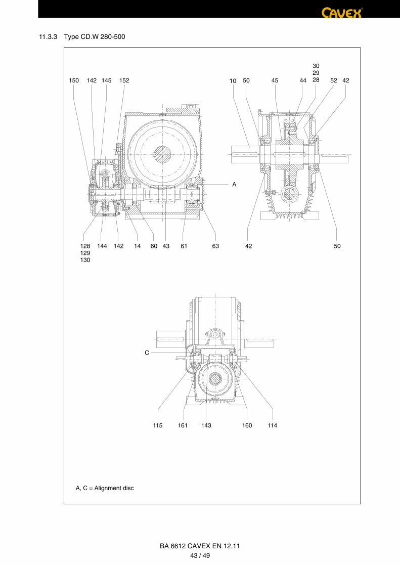
A, C, D = Alignment disc
142 524450150 45
D
A
42
302928145 152 10
143161115
C
160 114
50614314142144 4260150128129130
11.3.2 Type CD.W 180-250
®
BA 6612 CAVEX EN 12.1142 / 49
A, C = Alignment disc
142 524450150 45
A
42
302928145 152 10
143161115
C
160 114
50614314142144 4260 63128129130
®
BA 6612 CAVEX EN 12.1143 / 49
11.3.3 Type CD.W 280-500
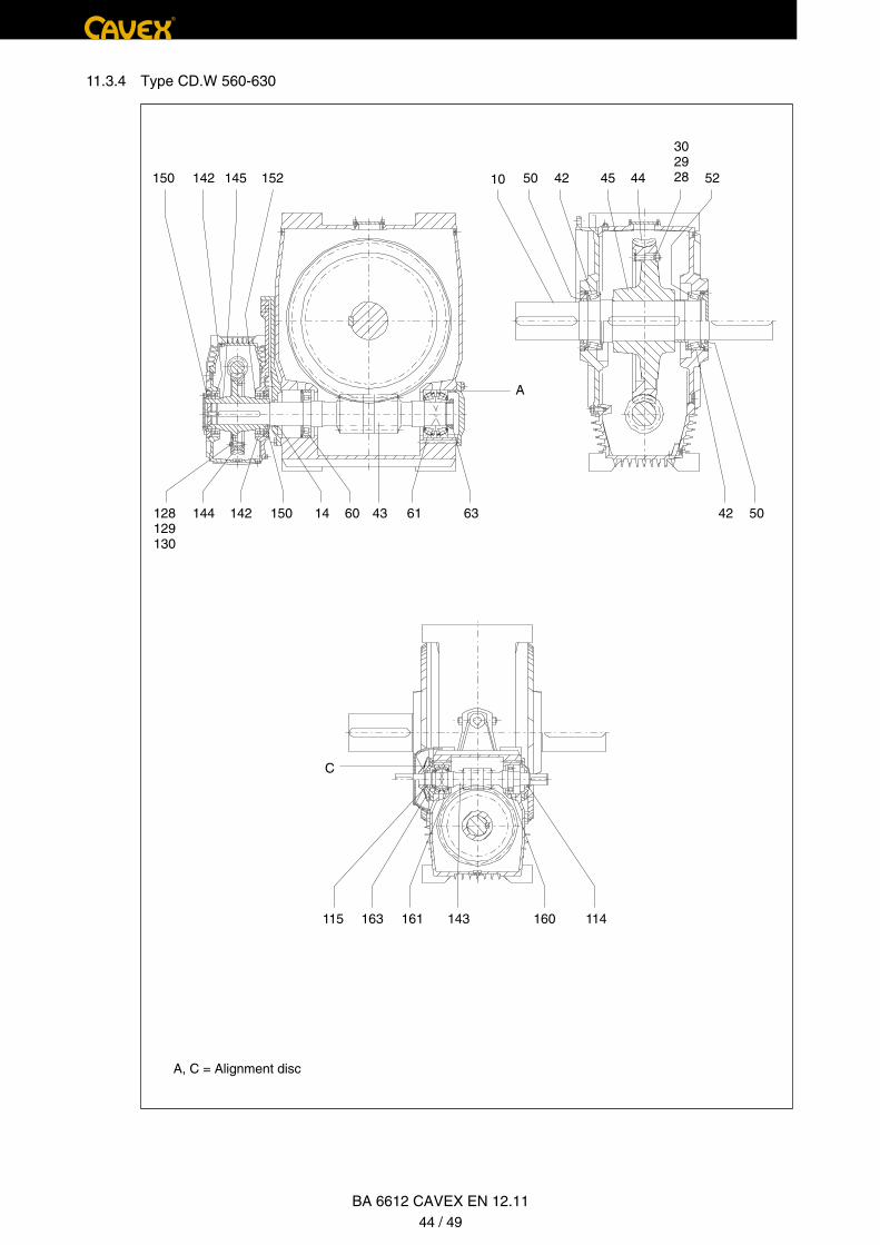
11.3.4 Type CD.W 560-630
A, C = Alignment disc
142 524450150 4542
302928145 152 10
A
506114142144 4263128129130
150 60 43
143161115
C
160 114163
BA 6612 CAVEX EN 12.1144 / 49
®

11.3.4 Type CD.W 560-630
A, C = Alignment disc
142 524450150 4542
302928145 152 10
A
506114142144 4263128129130
150 60 43
143161115
C
160 114163
BA 6612 CAVEX EN 12.1144 / 49
®
11.3.5 Type CD.A 100-160
A, B, C, D = Alignment disc (B only for size 100)
143161115
C
160 114
142 524450150 45 42
302928145 152
A
506114142144 744260 43
B
D
B
®
BA 6612 CAVEX EN 12.1145 / 49

11.3.6 Type CD.A 180-250
A, C, D = Alignment disc
143161115
C
160 114
142 524450150 45 42
302928145 152
A
506114142144 7442128129130
150 60 43
D
BA 6612 CAVEX EN 12.1146 / 49
®
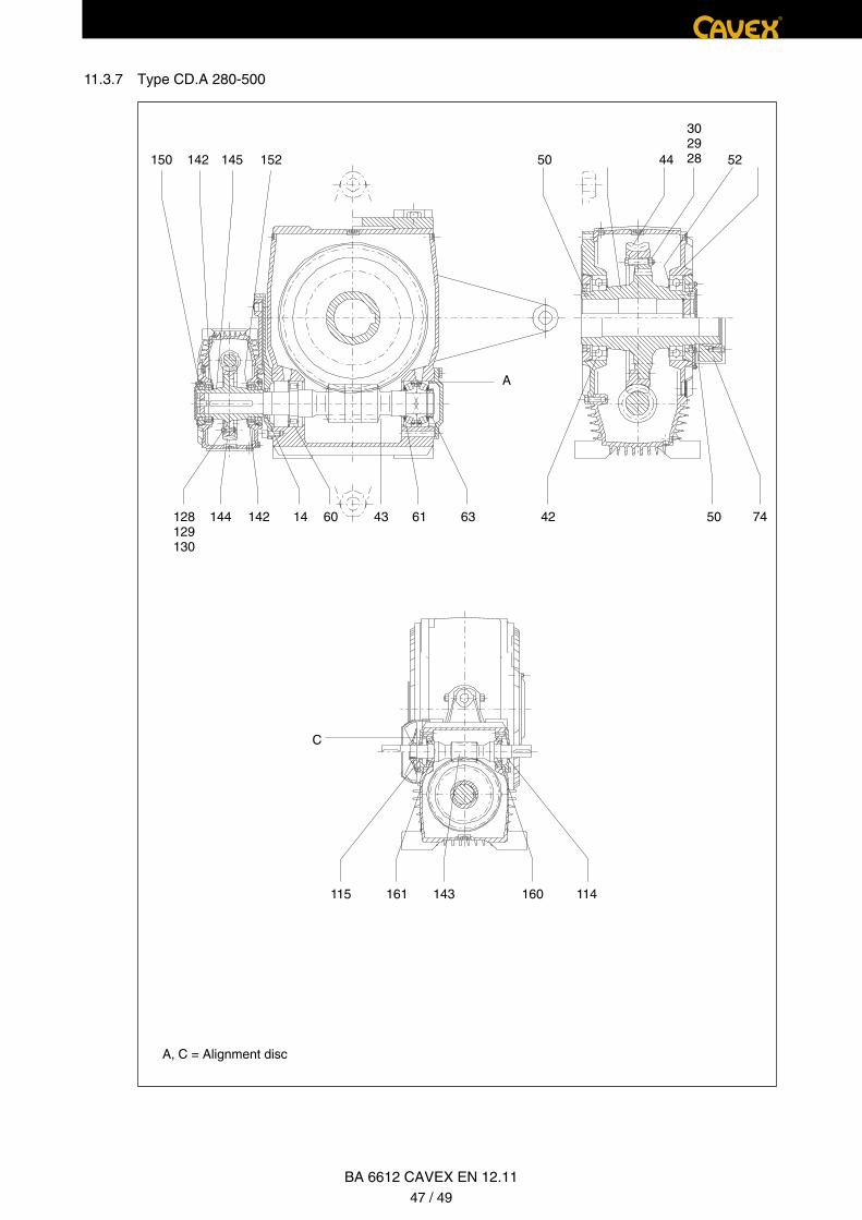
11.3.6 Type CD.A 180-250
A, C, D = Alignment disc
143161115
C
160 114
142 524450150 45 42
302928145 152
A
506114142144 7442128129130
150 60 43
D
BA 6612 CAVEX EN 12.1146 / 49
®
11.3.7 Type CD.A 280-500
A, C = Alignment disc
142 524450150
302928145 152
A
506114142144 7442128129130
60 43 63
143161115
C
160 114
BA 6612 CAVEX EN 12.1147 / 49
®
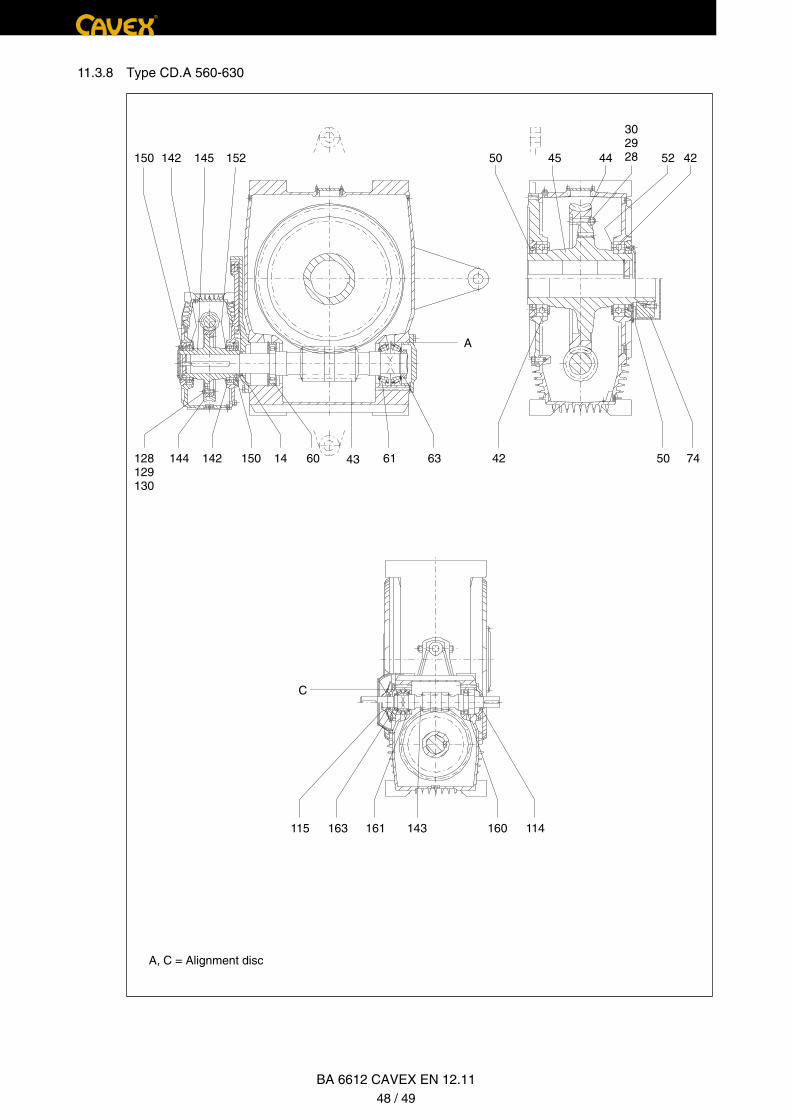
11.3.8 Type CD.A 560-630
A, C = Alignment disc
142 524450150 4245
302928145 152
A
506114142144 7442128129130
60 43 63150
143161115
C
160 114163
®
BA 6612 CAVEX EN 12.1148 / 49

11.3.8 Type CD.A 560-630
A, C = Alignment disc
142 524450150 4245
302928145 152
A
506114142144 7442128129130
60 43 63150
143161115
C
160 114163
®
BA 6612 CAVEX EN 12.1148 / 49
®
Bankverbindung:BW-Bank TübingenKto.-Nr.: 2 654 856(BLZ 600 501 01)Ust-IdNr.: DE277096258
Gerichtsstand:Registergericht Stuttgart HRA 726424Pers. haftende Gesellschaft CAVEX Verwaltungs-GmbHAmtsgericht Stuttgart HRB 737611Geschäftsführer: Dr.-Ing. Peter Leoni
G e r m a n D r i v e Te c h n o l o g y
CAVEX GmbH & Co. KGTübinger Straße 2D-72131 OfterdingenTel.: +49 (0) 74 73 95 546 - 0Fax: +49 (0) 74 73 95 546 - 88
Kontakt: [email protected]
Mehr erfahren Sie unter
w w w. C AV E X - G m b H . d e
Jens Heilemann Andy Schäfer
Declaration of Incorporationaccording to Directive 2006/42/EG, Appendix II, Part 1, Section B
chief operating officerHead of design & development
The manufacturer
CAVEX GmbH & Co. KGTübinger Straße 2D-72131 Ofterdingen
declares as follows:
The declaration refers to CAVEX-worm gear units models CD.. of size 63 to 630. The previously stated gear units are the incomplete machines in terms of directive 2006/42/EG.
The special technical documents according directive 2006/42/EEC, appendix VII B, are prepared.
The general safety and health protection requirements according directive 2006/42/EG, appendix I, are applied and followed.
1.1.1., 1.1.2., 1.1.3., 1.1.5., 1.2.6., 1.3.1., 1.3.2., 1.3.3., 1.3.4., 1.3.6., 1.3.7., 1.3.8.1., 1.4.1., 1.4.2.1.,1.5.1., 1.5.2., 1.5.3., 1.5.4., 1.5.5., 1.5.6., 1.5.7., 1.5.8., 1.5.9., 1.5.10., 1.5.11., 1.5.13., 1.5.14., 1.5.15.,1.6.1., 1.6.2., 1.6.5., 1.7.1., 1.7.1.1., 1.7.1.2., 1.7.3., 1.7.4., 1.7.4.1., 1.7.4.2., 1.7.4.3.
The manufacturer agrees to hand over upon special request to individual state officies the special documents according directive 2006/42/EG, appendix VII B. The documents will be transferred in electronic form.
The incomplete machine CAVEX-worm gear unit of the models CD.. of size 63 to 630 may only be taken intooperation if it was determined that the machine into which the incomplete machine CAVEX-worm gear unit ofthe models CD.. of size 63 to 630 is to be installed corresponds to the directive 2006/42/EG.
The following person is authorized to prepare the relevant technical documents:Jens Heilemann, head of design & development, CAVEX GmbH Co. KG, Tübinger Straße 2,D-72131 Ofterdingen
D-72131 Ofterdingen, 20.3.2012

Notes
®

Notes
®
Notes
®

www.CAVEX-GmbH.de
CAVEX GmbH & Co. KGTübinger Straße 2D-72131 OfterdingenTel.: +49 (0) 74 73 95 546 - 0Fax: +49 (0) 74 73 95 546 - 88
®