Instruction Manual AVTM830280 for Transformer · PDF fileAVTM830280 Rev. C July 2008...
42
AVTM830280 Rev. C July 2008 Instruction Manual AVTM830280 for Transformer Ohmmeter Catalog No. 830280 High-Voltage Equipment Read the entire manual before operating. Aparato de Alto Voltaje Antes de operar este producto lea este manual enteramente. M Valley Forge Corporate Center 2621 Van Buren Avenue Norristown, PA 19403 U.S.A. 610-676-8500 www.megger.com
Transcript of Instruction Manual AVTM830280 for Transformer · PDF fileAVTM830280 Rev. C July 2008...

AVTM830280 Rev. C
July 2008
Instruction Manual AVTM830280 for
Transformer Ohmmeter
Catalog No. 830280
High-Voltage Equipment Read the entire manual before operating.
Aparato de Alto Voltaje
Antes de operar este producto lea este manual enteramente.
M Valley Forge Corporate Center 2621 Van Buren Avenue Norristown, PA 19403 U.S.A. 610-676-8500 www.megger.com

M
Copyright 2008 by Megger. All rights reserved.
The information presented in this manual is believed to be adequate for the intended use of the product. If the product or its individual instruments are used for purposes other than those specified herein, confirmation of their validity and suitability must be obtained from Megger. Refer to the warranty information included in this instruction manual. Specifications are subject to change without notice.

AVTM830280 Rev C (07/2008) i
Table of Contents
1. GENERAL INFORMATION........................................................................................................1
1.1 About The Transformer Ohmmeter..................................................................................1
1.2 Features...........................................................................................................................2
1.3 Upon Receipt of Product..................................................................................................2
1.4 Unpacking and Inspection ...............................................................................................3
1.5 Safety First ......................................................................................................................3
1.6 How To Use This Manual................................................................................................3
1.6 Preparation for Use..........................................................................................................4
1.7 Line Supply Voltage........................................................................................................4
1.8 Repacking and Shipment .................................................................................................4
1.9 Specifications ..................................................................................................................5
1.10 Accessories Furnished .....................................................................................................6
1.11 Changes...........................................................................................................................7
1.12 Warranty .........................................................................................................................7 2. SAFETY ......................................................................................................................................9
2.1 Introduction.....................................................................................................................9
2.2 General Safety Precautions ..............................................................................................9
2.3 Safety In Using The Transformer Ohmmeter ................................................................. 10 3. OPERATING INSTRUCTIONS ................................................................................................. 11
3.1 Panel Controls and Operating Functions ........................................................................ 11
3.2 Principle of Operation ................................................................................................... 14
3.3 General Operating Instructions & Instrument Self-Check . ............................................ 15
3.4 Procedure for Single Phase Transformer Testing ........................................................... 16
3.5 Procedure for Three Phase Transformer Testing ............................................................ 21
3.6 Testing Transformers with Tap Changers ...................................................................... 31
3.7 Testing Voltage Regulators............................................................................................ 32 4. SERVICE AND MAINTENANCE .......................................................................................... 37
4.1 Description.................................................................................................................... 37

M
ii AVTM830280 Rev C (07/2008)
Figures
Figure 1: Panel Controls and Operating Functions ................................................................. 13
Figure 2: Single Winding Measurement..................................................................................... 17
Figure 3: Dual Winding Test....................................................................................................... 20
Figure 4 ........................................................................................................................................ 21
Figure 5 ........................................................................................................................................ 22
Figure 6 ........................................................................................................................................ 23
Figure 7 ........................................................................................................................................ 25
Figure 8- Typical 3 Phase Delta Network.................................................................................. 26
Figure 9 ........................................................................................................................................ 27
Figure 10 ...................................................................................................................................... 28
Figure 11 ...................................................................................................................................... 28
Figure 12 ...................................................................................................................................... 29
Figure 13 ...................................................................................................................................... 29
Figure 14 ...................................................................................................................................... 30
Figure 15 ...................................................................................................................................... 30
Figure 16: Odd Position Tap ...................................................................................................... 32
Figure 17: Even Position Tap ..................................................................................................... 32
Figure 18: Connection to a Regulator ....................................................................................... 34

AVTM830280 Rev C (07/2008) 1
1. GENERAL INFORMATION
1.1 ABOUT THE TRANSFORMER OHMMETER
The M Transformer Ohmmeter is a line-operated, field-portable instrument designed specifically to measure the dc resistance of all types of magnetic windings safely and accurately.
Its predominant use is the measurement of the dc resistance of all types of transformer windings within the defined ranges of current and resistance.
It can also test rotating machine windings and perform low-current resistance measurements on connections, contacts and control circuits.
Three features combine to make this instrument unique: dual measurement, load tap-changer testing and safety shutdown.
The dual set of potential inputs measure the resistance of the primary and secondary windings of a single- or three-phase transformer simultaneously. The dual reading characteristic will speed up the measurement when it is used to test windings on delta-delta connected windings on three-phase transformers.
Due to circulating currents induced when the test current is applied to the primary winding, this type of measurement is countered by the same current on the secondary winding. This action attenuates the circulating current and the reading time is improved tenfold.
The Transformer Ohmmeter is extremely useful when testing the windings and contact resistance on tap-changers with make-before-break contacts and voltage regulators.
The internal shutdown circuit will be triggered by a voltage kickback of a few microseconds if the tap-changer contacts are opened when the tap-changer circuit is operated through all of the tap positions.
This action will check for pitted or misaligned contacts as the instrument will shut down if either condition occurs.
Users are protected by the shutdown circuit safety feature: any inadvertent disconnection of a test lead or loss of power to the instrument will safely discharge the energy stored in the test sample.
The Transformer Ohmmeter's wide resistance range (1 micro-ohm to 1999 ohms) gives the optimum resolution for even the lowest winding resistance tested.

M
2 AVTM830280 Rev C (07/2008)
1.2 FEATURES
Direct digital reading saves time, no balancing is required.
Built-in discharge circuit safely discharges the specimen when test is completed, if lead accidentally disconnects or if power is lost.
Electromechanical safety indicator gives a visual indication of a charged or discharged specimen, even if power to the instrument is lost.
Two independent measuring channels allow simultaneous testing of primary and secondary windings or measurement of two phases at a time.
The sensitive surge detection circuitry monitors the contact operation of on-load tap-changers for the proper make-before-break sequence. If an open circuit condition exists, the instrument shuts down immediately.
High-accuracy, four-terminal bridge: no lead compensation required.
Electronically generated and regulated current supply overcomes high-inductance transformers quickly, allowing fast measurements to be taken. Display of measurement occurs only after test current stabilizes.
Wide resistance range is suitable for testing a wide variety of transformers.
Lightweight and portable, the Transformer Ohmmeter is ideal for use in shop or substation environments.
Overtemperature protection provides automatic current shutdown and LED indication to prevent instrument damage.
Instrument and accessories come in a foam-lined transport case.
1.3 UPON RECEIPT OF PRODUCT
Check the equipment received against the packing list to ensure that all materials are present. Notify Megger of any shortage (tel: 610-676-8500).
Examine the instrument for damage received in transit. If you find damage, file a claim with the carrier at once. Also notify Megger or its nearest authorized sales representative, and describe the damage in detail.
General Information
AVTM830280 Rev C (07/2008) 3
1.4 UNPACKING AND INSPECTION
Prior to shipment, this instrument was electrically tested and mechanically inspected and found to meet specifications and be free of mechanical defects.
After unpacking the instrument, visually inspect the instrument and accessories for damage. If evidence of damage is present YOU must contact the carrier who transported the unit and file a claim in writing. The shipping container and packing material should be retained for inspection by the carrier’s agent. Electrical operation per Section 3 should be checked as soon as possible after shipment.
1.5 SAFETY FIRST
Be sure to read the safety information in Section 2 thoroughly and observe all safety precautions and recommendations. Safety is the responsibility of the user.
1.6 HOW TO USE THIS MANUAL
Typographic conventions
Figures and tables are numbered in sequence by section
Numbered lists show procedural steps
Bullets list items and options
Warnings, Cautions and Notes
- Warnings alert you to conditions that are potentially hazardous to people
- Cautions alert you to possible damage to equipment
- Notes provide important explanation or assistance
F WARNING
DO NOT DISCONNECT LEADS BEFORE INDICATOR (7) IS OFF!!!

M
4 AVTM830280 Rev C (07/2008)
GCAUTION
It should be carefully noted that the jumper in Figure 3 be connected to opposite polarities of transformer in order to achieve correct results.
NOTE
For larger transformers, the resistance display (14) should be observed and resistance readings taken when the reading stabilizes. The drift in the indicated resistance reading is due to the inductance of the transformer. For small transformers the drift lasts for only a few seconds; for single-phase high voltage transformers (500 kV), the drift may last for a fraction of a minute; for large delta connected transformers the drift may last longer as a result of circulating current.
e.g. 345MVA, 500kV single-phase transformer requires approximately 2 minutes for the display to settle.
1.6 PREPARATION FOR USE
THIS INSTRUMENT IS DESIGNED TO OPERATE WITH HIGHLY INDUCTIVE TRANSFORMERS. ANY BREAK IN CONNECTION WHILE D.C. CURRENT IS FLOWING MAY RESULT IN HIGH VOLTAGE FLASHOVER. It is highly recommended that the operator familiarize himself with the controls and functions detailed in Section 3 prior to use. ALL SAFETY PROCEDURE AND PRECAUTIONS MUST BE FOLLOWED WHEN OPERATING ON LINES WITH LETHAL VOLTAGES OF HIGH CAPACITY.
1.7 LINE SUPPLY VOLTAGE
This instrument is shipped from the factory for operation on a 115 volt, 60Hz line. To prevent damage to the instrument, select the proper line voltage on the front panel selector before connection to a line supply.
1.8 REPACKING AND SHIPMENT
To insure proper shipment of this instrument, it is recommended that the original shipping case be retained. If being returned for calibration or service, please attach a card to the instrument specifying the owner, model and serial number and service required.

General Information
AVTM830280 Rev C (07/2008) 5
1.9 SPECIFICATIONS
The detailed specifications for the model are given below.
Input Power: 120/240 V, 50/60Hz, 350 VA
Measurement Principle: Electronic Thompson-type circuit
Current Supply Principle: Electronically generated and regulated
Test Current: Switch selectable
Ranges: 5 mA, 50 mA, 500 mA, 5 A (dc)
Open Circuit Test Voltage:
30 V dc
Rating: Continuous use on all ranges
Indication: Mechanical indicator (indication of current flow even when instrument turned off or unplugged). Output current displayed on display "A"(in %).
Over Temperature Protection:
Automatic current shutdown with L.E.D. indication of over temperature condition for 5A range.
Resistance Measurements:
Inputs: Two isolated high impedance inputs, each with separate range control and protection provided for flashover caused by inductive kickback
Ranges (ohms):
Nominal Resolution Maximum Display
2m 0.001m 1.999m
20m 0.01m 19.99m
200m 0.1m 199.9m
2 0.001 1.999
20 0.01 19.99
200 0.1 199.9
2000 1.0 1999
Accuracy: ±0.5% reading, ±0.5% full scale (when current has stabilized).

M
6 AVTM830280 Rev C (07/2008)
Overrange: Indicated by leading number 1 displayed with all other digits blanked.
Operation:
Environmental: Operating: 32 to 104º F (0 to 40ºC) RH to 80%
Storage: -40 to 149º F (-40 to +65ºC)
Temperature Coefficients:
±0.05% of applicable accuracy specification per ºC of resistance range.
Displays: Two high-temperature, 0.7 in. (18 mm), liquid crystal 3 ½-digit displays showing 1999 at full scale. Update rate is approximately three times per second.
Physical: Instrument and accessories supplied with portable foam lined carrying case. Case has hinged opening from above with a lockable latch.
Sizes: Instrument: 11 H x 16 W x 10.5 D in.
280 H x 406 W x 267 D mm
Case: 13 H x 20 W x 21 D in.
330 H x 508 W x 533 D mm
Weight: Instrument: Net 40 lb (18 kg)
Shipping: 75 lb (34 kg)
1.10 ACCESSORIES FURNISHED
Each instrument is supplied complete with:
Two sets of potential leads, 33 ft (10 m)
One set of current leads, 33 ft (10 m)
One shorting lead, 9.9 ft (3 m)
Universal bushing adapters (set of 4)
AC power cord
One operating and instruction manual
One transport case

General Information
AVTM830280 Rev C (07/2008) 7
1.11 CHANGES
Please note that this instrument is subject to continuous development and improvement. This instrument may therefore incorporate minor changes in detail from the information contained herein.
1.12 WARRANTY
Megger warrants this instrument sold by us or our authorized agents, to be free from defects in material and workmanship for a period of 12 months from date of shipment. During the warranty period, Megger will, at our option, repair or replace the Instrument or part thereof which proves to be defective providing:
(1) The Instrument is returned properly packed and transportation prepaid with prior authorization from us or our appointed agent,
(2) The Instrument has not been altered, modified or repaired by unauthorized personnel and,
(3) That our examination discloses to our satisfaction that any improper operation or failure was the result of defective material or workmanship and was not the result of improper use, negligence or accident, exceeding environmental limits, or connecting the instrument to incompatible equipment.
This warranty is exclusive and is given and accepted in lieu of all other warranties, express or implied, and constitutes fulfillment of all our liabilities to the purchaser. Megger specifically disclaims the implied warranties of merchantability and fitness for a specific purpose. We assume no liability, in any event, for consequential damages, for anticipated or lost profits, for personal injury due to use or accident, for incidental damages or loss of time or other losses incurred by the purchaser or any third party in connection with instruments covered by this warranty or otherwise.

M
8 AVTM830280 Rev C (07/2008)
M

AVTM830280 Rev C (07/2008) 9
2. SAFETY
2.1 Introduction
Megger has designed the Transformer Ohmmeter and the recommended operating procedures with careful attention to safety. It performs formal safety reviews of the initial design and any subsequent changes to all new Megger products. The safety review covers areas over and above those included in applicable IEC and ANSI standards.
Regardless of these efforts, it is not possible to eliminate all hazards from electrical test equipment or to foresee every possible hazard. You are therefore urged not only to follow the safety rules in this manual, but also to consider carefully all safety aspects of the test before proceeding. Safety is the responsibility of the user.
The design of this equipment follows safety specifications IEC 1010-1 and ANSI/ISA 582.01 and meets the requirements for Class I, Installation Category II equipment.
Megger recommends that a qualified operator attend the system at all times while it is in operation. Only qualified service personnel should replace components or make internal adjustments.
2.2 General Safety Precautions
The equipment and the cable to which the Transformer Ohmmeter connects are sources of high-voltage electrical energy. Observe the following safety precautions:
Observe all safety warnings on the equipment. They identify areas of immediate hazard that could result in injury or death.
Use this equipment only for the purposes described in this manual.
Treat all terminals of high-voltage power equipment as potential electric shock hazards.
Use all practical safety precautions to prevent contact with energized parts of the equipment and related circuits.
Use suitable barriers, barricades, or warnings to keep persons not directly involved with the work away from test activities.
Never connect the test equipment to energized cables.
Do not connect to energized equipment or use in an explosive atmosphere.

M
10 AVTM830280 Rev C (07/2008)
Use the grounding and connection procedures recommended in this manual.
Observe strictly the warning and caution notices used throughout this manual (see ‘How to Use This Manual” on page 3).
2.3 SAFETY IN USING THE TRANSFORMER OHMMETER
Safety is the responsibility of the user. When applying current to a transformer with very high inductance, care should always be taken not to remove current leads while current is still flowing. This causes an extremely high voltage to develop across the point where current is broken. With correct conditions, this voltage may even be lethal to the operator breaking the current path.
The Megger Transformer Ohmmeter has built-in safety protection. This safety feature is present in the form of an alternate route through either of the potential leads.
Example: If a current lead is disconnected while current is flowing through the transformer, the current will flow through the alternate path of the potential lead without damage to instrument or electrical shock to operator.
FWARNING
It is very important, therefore, not to connect potential leads on top of or to close to current leads. In this way, if one lead falls off the transformer, the other lead will automatically follow.
FWARNING
The Transformer Ohmmeter is protected in the event of both potential and current lead falling off at the same time. This does not mean, however, that the operator will not feel the high voltage that will be developed (if he is standing near the area where the lead disconnects).
AVTM830280 Rev C (07/2008) 11
3. OPERATING INSTRUCTIONS
3.1 PANEL CONTROLS AND OPERATING FUNCTIONS
This section details and describes the operating functions of the Transformer Ohmmeter. Refer to Figure 1.
1. Power ON.
Flipping this switch upwards will activate the instrument. With current control (4) in the center position, ready LED (5) will illuminate 15 seconds after the instrument is turned on.
2. Line Input Socket.
This international line socket also contains the line fuse and a spare fuse.
3. Line Voltage Selector.
The instrument is configured at the factory for 115 volt operation. Failure to select the correct line voltage could result in damage to the instrument.
4. Current Control.
This switch is used to initiate current flow from the instrument (up) and to activate a process whereby the device under test is discharged (down).
5. Ready L.E.D.
This L.E.D. must be illuminated to initiate a given test. This indicator will be inactive under the following conditions
the test has been initiated
the test specimen is undergoing discharge
the surrounding electrical interference exceeds the instruments suppression capability
6. Over Temperature L.E.D.
This L.E.D. illuminates when the instruments internal components have exceeded their thermal capacity. This condition typically occurs after extended operation on the 5A range. A period of approximately 20 minutes is required before the instrument will again operate.
7. Current Light Emitting Diode (LED).
This low-energy consuming electronic component signals current flow through the output terminals (9) and/or excitation voltage.

M
12 AVTM830280 Rev C (07/2008)
8. Potential Input "A".
Connected across a transformer winding, this input measures the winding voltage drop and displays the related resistance value on display "A" (15).
9. Current Output.
Connected across a transformer winding, this output supplies a selected D.C. current through the winding.
10. Potential Input "B".
Connected across a transformer winding, this input measures the winding voltage drop and displays the related resistance value on display "B" (16).
11. Current Selector.
This switch allows selection of the test current which will be supplied to the transformer windings via output terminals (9). It also changes resistance ranges, increasing resolution with an increase in the test current range.
12. Range Selector "A".
This switch changes the resistance range for potential input "A".
13. Range Selector "B".
This switch changes the resistance range for potential input "B".
14. Display Selector.
This switch selects the value to be monitored on display "A". (Either percent of the test current or the load resistance).
15. Display "A".
Value displayed is either the resistance related to potential input "A" (8) or percent of the test current output (9).
16. Display "B".
Value displayed is resistance related to potential input "B" (10).
17. Resistance Range Table.
This table shows the maximum allowable resistance for the combination of current selector (11) and range selector (12 or 13).

Operating Instructions
AVTM830280 Rev C (07/2008) 13
FIGURE 1: PANEL CONTROLS AND OPERATING FUNCTIONS

M
14 AVTM830280 Rev C (07/2008)
3.2 PRINCIPLE OF OPERATION
The Megger Transformer Ohmmeter measures the resistance of a transformer winding by:
1. Applying a D.C. current through the transformer winding and an internal standard current shunt.
2. Measuring the D.C. voltages across the winding and the shunt.
3. Comparing the two voltages and displaying their ratio as resistance.
This method neglects lead resistance because it is independent of current. All readings are direct and therefore no multiplication factor need be applied when changing current ranges.
When testing transformers having large inductance, the D.C. current source must be extremely stable. This is seen in the formula for the D.C. voltage across an inductor:
V D.C. = I x R + L dI/dt
Where,
V D.C. = D.C. voltage across transformer winding.
I = D.C. current through transformer winding.
R = Resistance of the Tx winding.
L = Inductance of Tx winding.
dI/dt = Changing value of current (ripple) (Equals "0" for steady D.C.).
For optimum operation, the Transformer Ohmmeter resistance displays will only stay on with test current larger than 55% of set current range. If current does not reach the required 55%, resistance display will not show any value.

Operating Instructions
AVTM830280 Rev C (07/2008) 15
3.3 GENERAL OPERATING INSTRUCTIONS & INSTRUMENT SELF-CHECK (see Figure 1).
1. Connect line cord to instrument and plug into power socket (ensure that line voltage selector (3) is set to correct voltage).
2. Set the following:
a. Current Control (4): Middle position. b. Display Selector (14): Up position. c. Range Selector "A" (12): Left most position. d. Range Selector "B" (13): Right most position. e. Current Selector (11): 5mA.
3. Short current output (9); Short potential input "A" (8).
4. Turn power switch (1) "ON". "Ready" L.E.D. (5) should illuminate.
5. Push current control switch (4) up to initiate current flow. Release when current indicator (7) comes on.
6. Observe display "A". Indication should show an increasing number with "%" L.E.D. illuminated.
7. Reading should settle. This value has no effect on accuracy of resistance readings.
8. Switch display selector (14) down.
9. Indication should be "000" and ohms L.E.D. illuminated.
10. Set momentary current control (4) "down". Current should discharge and current flow indicator (7) should turn off.
11. If desired, set current selector (11) to another current and proceed with steps 3 to 11.
ALTERNATE
1. For step 3 above; place a standard current shunt or standard resistor (of known value, less than 2,000 ohms) between current output (9). Place potential input "A" (8) across inside of current shunt.
2. Following steps 1 to 11 above (with the exception of step 3), the value of the standard shunt should be read on display "A".
FWARNING
When testing a transformer or regulator, make sure that a good ground is placed on the test specimen as shown on all connection diagrams.

M
16 AVTM830280 Rev C (07/2008)
3.4 PROCEDURE FOR SINGLE PHASE TRANSFORMER TESTING
This procedure describes only the basic connections and control settings for a single phase, two winding transformer. Following this description will be connections and any special notes for three phase transformers. Different types and sizes will vary the settling time of the test current and hence vary the time required to obtain readings. Because all input and output terminals are totally isolated on the Transformer Ohmmeter, no grounds need be removed from the transformer under test.
See Section 3.1 for explanation and location of controls.
3.4.1 SINGLE WINDING TEST
See Figure 2 for connection to the test transformer.
PROCEDURE:
1. Connect line cord to unit and plug into 120V socket.
2. Set the following conditions:
a Display Selector (14): up position.
b. Range Selector "A" (12):
left most position.
c. Range Selector "B" (13):
right most position.
d. Current Selector (11): to desired test current (guide by resistance table on face plate).
3. Connect current output (9) to test specimen winding. See Figure 2.
4. Connect "B" potential input (10) to test specimen winding. Do not clip potential leads on to the current leads, since this will add contact resistance to the measurement. Potential leads should always be placed inside (between) current leads. See Figure 2.
5. Turn power switch (1) "ON". "READY" L.E.D. (5) should illuminate.
6. Push current control switch (4) up to initiate current flow. Release when current indicator (7) comes ON.
7. Display "A" (15) indicates current output (in %). As output current approaches steady value, display "B" (16) comes on and indicates resistance of specimen.
Operating Instructions
AVTM830280 Rev C (07/2008) 17
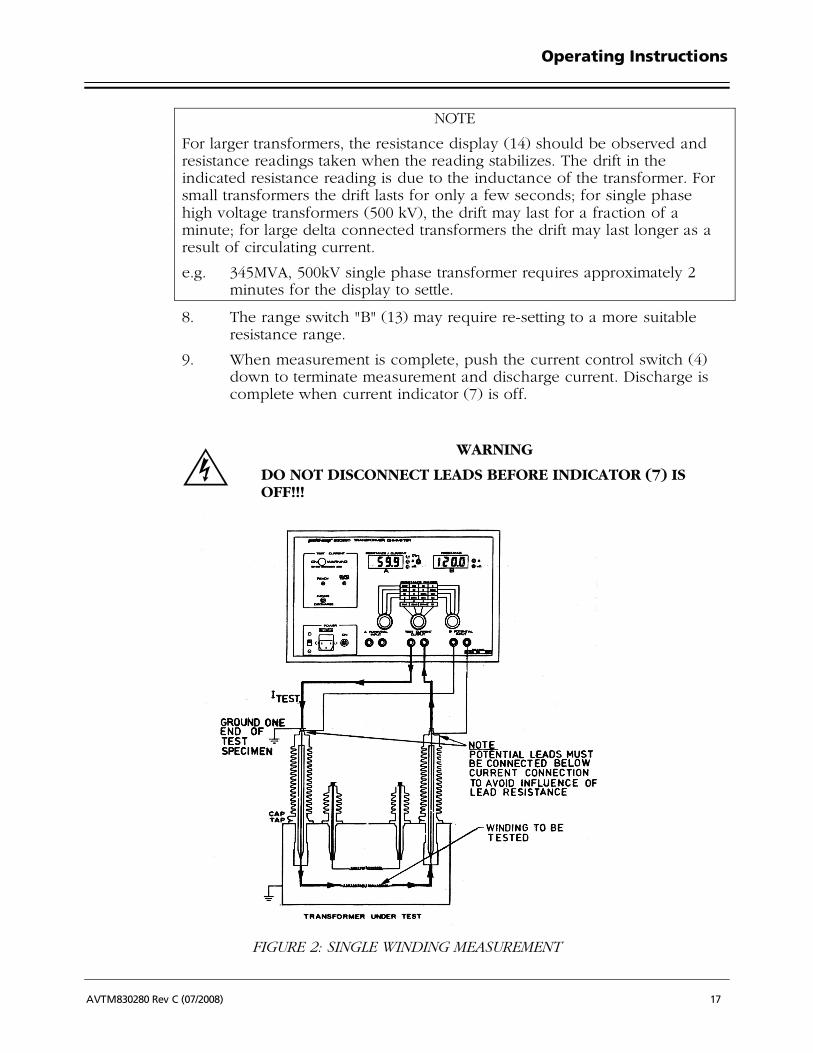
NOTE
For larger transformers, the resistance display (14) should be observed and resistance readings taken when the reading stabilizes. The drift in the indicated resistance reading is due to the inductance of the transformer. For small transformers the drift lasts for only a few seconds; for single phase high voltage transformers (500 kV), the drift may last for a fraction of a minute; for large delta connected transformers the drift may last longer as a result of circulating current.
e.g. 345MVA, 500kV single phase transformer requires approximately 2 minutes for the display to settle.
8. The range switch "B" (13) may require re-setting to a more suitable resistance range.
9. When measurement is complete, push the current control switch (4) down to terminate measurement and discharge current. Discharge is complete when current indicator (7) is off.
FWARNING
DO NOT DISCONNECT LEADS BEFORE INDICATOR (7) IS OFF!!!
FIGURE 2: SINGLE WINDING MEASUREMENT

M
18 AVTM830280 Rev C (07/2008)
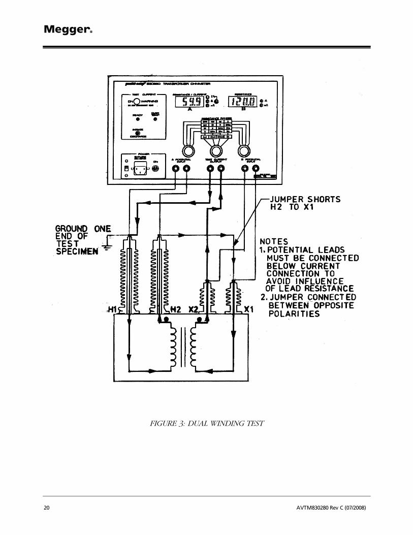
3.4.2 DUAL WINDING TEST
This procedure described below is for testing both windings (high and low) on a single phase transformer.
See Figure 3 for connection to test transformer.
GCAUTION
It should be carefully noted that the jumper in Figure 3 be connected to opposite polarities of transformer in order to achieve correct results.
PROCEDURE:
1. Connect line cord to unit and plug into line socket.
2. Set the following conditions:
a. Display Selector (14): down position.
b. Range Selector "A" (12):
left most position.
c. Range Selector "B" (13):
right most position.
d. Current Selector (11): to desired test current. Best results will be at highest current (guide by resistance table on face plate).
3. Connect current output (9) to test specimen winding. See Figure 3.
4. Connect "A" potential input (8) to H1 and H2 terminals of test transformer. Potential leads should be placed inside current lead and shorting jumper.
5. Connect "B’ potential input (10) to X1 and X2 terminals of test transformer. Potential leads should be placed inside current lead and shorting jumper.
6. Turn power Switch (1) "ON". "READY" L.E.D. (5) should illuminate.
7. Push current control switch (4) up to initiate flow. Release when current indicator (7) comes on.
8. Observe display "A". Indication should show an increasing value with "%" L.E.D. illuminated.
9. When reading settles indication will automatically switch to "ohm" indication and display resistance of H1 - H2 winding.
10. Display "B" will now indicate resistance of X1 - X2 winding.
Operating Instructions
AVTM830280 Rev C (07/2008) 19
11. To obtain best resolution for both display A and B, adjust range selectors (12 and 13).
12. When measurement is complete, push the momentary current control switch (4) down to terminate measurement and discharge current. Discharge is complete when current indicator (7) is OFF.
F WARNING
DO NOT DISCONNECT LEADS BEFORE INDICATOR (7) IS OFF!!!
M
20 AVTM830280 Rev C (07/2008)
FIGURE 3: DUAL WINDING TEST

Operating Instructions
AVTM830280 Rev C (07/2008) 21
3.5 PROCEDURE FOR THREE PHASE TRANSFORMER TESTING
The following section details connections to be made on three phase transformers. These connections detail the different methods to be used in order to obtain the best results. The measurements taken will be for one winding at a time. The following connection diagrams (Figures 4 to 7), therefore, are to be used in conjunction with procedure "3.4.1 Single Winding Test". This procedure is to be used when performing three phase transformer testing. The only changes will be placement of leads.
PROCEDURE:
1. THREE PHASE WYE CONFIGURED WINDING WITH NEUTRAL
READING OBTAINED IS DIRECT, RESISTANCE OF C-N WINDING
FIGURE 4

M
22 AVTM830280 Rev C (07/2008)
2. THREE PHASE WYE CONFIGURED WINDING, NO NEUTRAL BROUGHT OUT
READING OBTAINED IS DIRECT, RESISTANCE OF C-N WINDING
FIGURE 5
Operating Instructions
AVTM830280 Rev C (07/2008) 23
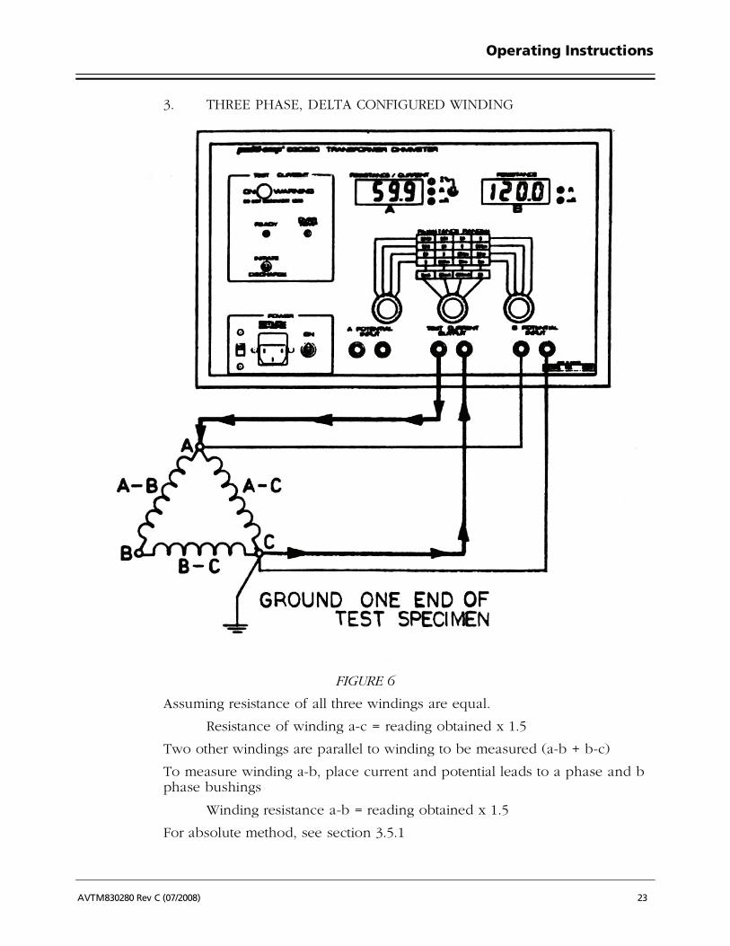
3. THREE PHASE, DELTA CONFIGURED WINDING
FIGURE 6
Assuming resistance of all three windings are equal.
Resistance of winding a-c = reading obtained x 1.5
Two other windings are parallel to winding to be measured (a-b + b-c)
To measure winding a-b, place current and potential leads to a phase and b phase bushings
Winding resistance a-b = reading obtained x 1.5
For absolute method, see section 3.5.1

M
24 AVTM830280 Rev C (07/2008)
3.5.1 TESTING DELTA-DELTA CONFIGURED WINDINGS
Although Delta-Delta transformers are not very common, they are present for various requirements. The testing of a Delta-Delta for winding resistance is usually a very time consuming procedure. This is because the two windings resemble two closed loop inductors. When energy is brought into the inductors, this energy (in the form of D.C. current) continually circulates within each winding. The correct balance time can take up to 30 minutes, which far exceeds the time restriction of many tests.
The method for testing this configuration quickly requires that both the high side and low side be connected in series with the Transformer Ohmmeter’s current source (see Figure 7). By having the two windings in opposite polarity, the internal circulating currents settle very quickly to obtain a balance, and discharge with the same speed. Test time, for example, is reduced from 14 minutes to 30 seconds on a 300k VA Delta-Delta transformer. Even if only one side of the transformer needs to be tested, connecting both high and low windings in series will speed the test up considerably.

Operating Instructions
AVTM830280 Rev C (07/2008) 25
FIGURE 7

M
26 AVTM830280 Rev C (07/2008)
3.5.2 CALCULATION OF DELTA WINDING RESISTANCE
In the electrical power industry we find a lot of equipment that is connected in delta. An ordinary ohmmeter, when measuring a delta connected set of resistances, measures one resistance shunted by the other two series connected resistances. Calculating the value of the resistances is easy when they are equal, since the measured value can be multiplied by 1.5. When the resistances are not equal, one must solve three simultaneous equations in order to find the resistance values. This can be rather involved and time consuming.
The purpose of this technical note is to present a method of calculating the resistance values of a delta-connected network using the Megger 830280 Ohmmeter. The calculation is simple and can be easily done on a four function electronic calculator.
Measuring Procedure.
The complete measuring procedure involves two different connections for each of the three phases that are measured. The procedure gives three resistance values and six ratios that are used to calculate the individual, delta connected, resistors. The connections and readings to be taken are shown on the appended drawings.
The results of the measurement and calculations are entered in the table shown below to a network as defined thus:
FIGURE 8- TYPICAL 3 PHASE DELTA NETWORK
Values of steps 1-9 are obtained by referring to the preceding pages.
Phase Resistance Ratio Inverse Ratio
A - B Step i Step ii Step iii
B - C Step iv Step v Step vi
C - A Step vii Step viii Step ix

Operating Instructions
AVTM830280 Rev C (07/2008) 27
The values of the resistances are calculated from the following equations:
Equation 1 R1 i1 v ix
v ix=
+ +
+
Equation 2 R2 iv1 viii iii
viii iii=
+ +
+
Equation 3 R3 vii1 ii vi
ii vii=
+ +
+
The lower case roman numeral values refer to the numerical values obtained in the appropriate step of the measuring procedures (see table on previous page).
Example: Assuming a delta network as shown below,
FIGURE 9
The results of the nine steps of the measurement procedure (follow on the preceding pages) should result in the following table:
Phase Resistance Ratio Inverse Ratio
A - B (i) 0.833 (ii) 0.666 (iii) 1.500
B - C (iv) 1.333 (v) 3.000 (vi) 0.333
C - A (vii) 1.500 (viii) 0.500 (ix) 2.000
Using equations 1, 2 and 3 from above, we arrive at the following values:
R1 = 1 ohm; R2 = 2 ohms; R3 = 3 ohms.
Conclusion
A procedure that allows the individual resistance values of delta-connected equipment to be easily calculated has been presented. Although the method, with certain modifications, is applicable to most ohmmeters, it is especially applicable when using the Megger 830280 Transformer Ohmmeter for testing delta connected transformers.

M
28 AVTM830280 Rev C (07/2008)
FIGURE 10
FIGURE 11
Step i Step ii
1. Connect transformer as shown. 1. Connect transformer as shown.
2. Following test procedures of instruction manual, record R A-B on meter "B".
2. Following test procedures of instruction manual, record:
a. Meter "A";
b. b. Meter "B".
Step i = R A-B Step ii = Meter "A" Meter "B"
Step iii
1. Using procedure of Step ii,
Step ii = Meter "B" Meter "A"

Operating Instructions
AVTM830280 Rev C (07/2008) 29
FIGURE 12
FIGURE 13
Step iv Step v
1. Connect transformer as shown. 1. Connect transformer as shown.
2. Following test procedures of instruction manual, record R B-C on meter "C".
2. Following test procedures of instruction manual, record:
a. Meter "A"
b. Meter "B".
Step iv = R B-C Step v =
Meter "A" Meter "B"
Step vi
1. Using procedure of Step v,
Step vi =
Meter "B" Meter "A"

M
30 AVTM830280 Rev C (07/2008)
FIGURE 14
FIGURE 15
Step vii Step viii
1. Connect transformer as shown. 1. Connect transformer as shown.
2. Following test procedures of instruction manual, record R A-C on meter "B".
2. Following test procedures of instruction manual, record:
a. Meter "A";
b. b. Meter "B".
Step vii = R A-C Step viii =
Meter "A" Meter "B"
Step ix
Using procedure of Step viii,
Step ix = Meter "B" Meter "A"

Operating Instructions
AVTM830280 Rev C (07/2008) 31
3.6 TESTING TRANSFORMERS WITH TAP CHANGERS
Many transformers used today have taps built into them. These taps allow ratio to be increased or decreased by fractions of a percent. Any of the ratio changes involve a mechanical movement of a contact from one position to another. It is this contact that need to be checked by way of its resistance.
The contact may go bad for a number of reasons.
1. Misaligned when manufactured causing insufficient surface contact. Full load current overheats contact surface causing it to burn.
2. Current passing through contact exceeds full load rating.
3. Tap changing operation not "Make before break" creating internal arcing of contact surface.
4. An off-load tap changer is switched while on load. Contact surface becomes pitted and uneven.
Tap changers are divided into two types; On-load and Off-load. The "On-load" tap changer allows selection of ratio change while the transformer is in service. This would mean the ratio of a transformer can be changed while power (current) is still passing through it. The most common example of this type of "On-load" tap changer is a "Voltage Regulator".
The Transformer Ohmmeter is ideally suited to test on-load tap changers because the instrument can be left ON while changing from tap to tap. This allows the operator to take measurements very quickly without discharging, then re-charging the transformer for every tap. The Transformer Ohmmeter will re-balance after every tap change. If the tap is defective (open) or if there is even a fraction of time (1 m.s.) where circuit is open, the Transformer Ohmmeter will automatically go into its discharge cycle. This gives the operator a clear indication of a possible fault within the tap changer. For this OPEN condition, no damage will be done to the transformer by the Transformer Ohmmeter’s D.C. current.
The second type of tap changer is the "Off-load". This is not as common as On-load because in order to change taps, the transformer has to be taken out of service or at least disconnected from the load. This type of tap changer may typically go bad faster than an On-load because of inadvertent changing of taps while still in service. The Transformer Ohmmeter will test this transformer, but it must be discharged between tap changes. If the Transformer Ohmmeter is not discharged of test current between tap changes, the instrument will automatically discharge upon sensing a break in the current path. Because of its low 5A, 30V D.C. current, no real damage will be done to the tap surface contact by the Transformer Ohmmeter when switching of tap changer occurs.
When actually testing tap changers, follow procedure of the transformer under test while keeping this section in mind.

M
32 AVTM830280 Rev C (07/2008)
3.7 TESTING VOLTAGE REGULATORS
This procedure describes the basic connections to a single phase regulator. The main test for a regulator is the evaluation of the condition of the tap positions. Because there are a large number of taps (typical 32), this test would normally take a very long time. With the Megger Transformer Ohmmeter, this test time is drastically reduced because the instrument will stay on while changing tap positions. This means charge and discharge cycles are virtually eliminated.
All regulators have internal bridging reactors. It is because of these reactors that balance time for the Transformer Ohmmeter will vary. On odd position taps, balance time will be longer than even positions. This is due to circulating current generated when on odd positions and is shown below:
FIGURE 16: ODD POSITION TAP
FIGURE 17: EVEN POSITION TAP

Operating Instructions
AVTM830280 Rev C (07/2008) 33
See Figure 18 for connection to the voltage regulator.
PROCEDURE
1. Connect line cord to unit and plug into 120V socket.
2. Set the following conditions:
a. Display Selector (14): up position.
b. Range Selector "A" (12): left most position.
c. Range Selector "B" (13): right most position.
d. Current Selector (11): 5A nominal (guide by resistance table on face plate).
3. Connect current output (9) to test specimen winding.
4. Connect "B" potential input (10) to test specimen winding. Do not clip potential leads on to the current leads, since this will add contact resistance to the measurement. Potential leads should always be placed inside (between) current leads. See Figure 18.
5. Turn power switch (1) "ON". "READY" L.E.D. (5) should illuminate.
6. Push current control switch (4) up to initiate current flow. Release when current indicator (7) comes ON.
7. Display "A" (15) indicates current output (in %). As output current approaches steady value, display "B" (16) comes on and indicates resistance of specimen.
8. The range switch "B" (11) may require re-setting to a more suitable resistance range.
9. When measurement is complete, push the current control switch (4) down to terminate measurement and discharge current. Discharge is complete when current indicator (7) is off.
G CAUTION
Current selector (11) should be at highest acceptable current in order to obtain best results.
FWARNING
DO NOT DISCONNECT LEADS BEFORE INDICATOR (7) IS OFF!!!

M
34 AVTM830280 Rev C (07/2008)
FIGURE 18: CONNECTION TO A REGULATOR

Operating Instructions
AVTM830280 Rev C (07/2008) 35
M


AVTM830280 Rev C (07/2008) 37
4. SERVICE AND MAINTENANCE
4.1 DESCRIPTION
Megger maintains a complete instrument repair service. Should this instrument ever require repairs, we recommend it be returned to the factory for repair by our instrument specialists.
When contacting our service department, complete information concerning the trouble and any steps taken in attempting repair should be given. The catalog number and serial number of the instrument should also be specified. When returning instruments for repairs, either in or out of warranty, they should be shipped Prepaid and Insured, and marked for the attention of the Repair Department.
M Valley Forge Corporate Center 2621 Van Buren Avenue Norristown, PA 19403 U.S.A. 610-676-8500 www.megger.com

M
38 AVTM830280 Rev C (07/2008)
M