INSTRUCTION MANUAL AQ B398 - Busbar protection IED · The AQ 398 busbar protection IED is intended...
76
INSTRUCTION MANUAL AQ B398 - Busbar protection IED
Transcript of INSTRUCTION MANUAL AQ B398 - Busbar protection IED · The AQ 398 busbar protection IED is intended...

INSTRUCTION MANUAL
AQ B398 - Busbar protection IED
Instruction manual –AQ B398 busbar protection IED 2 (76)
Revision 1.00
Date 1.1.2012
Changes - The first revision
Revision 1.01
Date 9.2.2015
Changes - Current and voltage measurement descriptions revised.
Revision 1.02
Date 17.12.2019
Changes - Updated construction and installation chapter
Instruction manual –AQ B398 busbar protection IED 3 (76)
TABLE OF CONTENTS
1 GENERAL ..................................................................................................................... 5
2 MAIN CHARACTERISTICS OF THE AQ B398 TYPE BUSBAR PROTECTION
SYSTEM ................................................................................................................................ 6
3 SOFTWARE SETUP OF THE IED ................................................................................ 7
3.1 Measurements .............................................................................................................. 7
3.1.1 Current measurement and scaling ...................................................................... 7
3.1.2 Voltage measurement and scaling .................................................................... 10
3.2 Busbar differential protection function .......................................................................... 14
3.2.1 The busbar replica evaluation ........................................................................... 14
3.2.2 The differential current calculation .................................................................... 14
3.2.3 The biasing current calculation ......................................................................... 15
3.2.4 Differential characteristics ................................................................................. 16
3.2.5 Offset setting (“Max.I_load”) .............................................................................. 16
3.2.6 Voltage breakdown condition ............................................................................ 17
3.2.7 The check zone ................................................................................................ 18
3.2.8 Saturated waveform compensation ................................................................... 18
3.2.9 Directionality check ........................................................................................... 19
3.2.10 Current transformer failure detection ................................................................. 19
3.2.11 Checking the disconnector status signals ......................................................... 20
3.2.12 Measured values .............................................................................................. 20
3.2.13 Behavior of the algorithm in internal fault .......................................................... 21
3.2.14 Behavior of the algorithm in external fault ......................................................... 23
3.2.15 Setting parameters ........................................................................................... 31
3.3 Breaker failure protection function ............................................................................... 33
3.3.1 Function block symbol ...................................................................................... 33
4 BUSBAR DIFFERENTIAL PROTECTION VARIANTS................................................. 35
4.1 Distributed busbar protection ....................................................................................... 35
4.2 Centralized busbar differential protection .................................................................... 36
4.2.1 Centralized busbar protection hardware configurations .................................... 36
4.3 Generic busbar protection application example ........................................................... 39
4.4 Busbar differential protection software configuration ................................................... 40
4.4.1 Function blocks ................................................................................................. 40
4.4.2 Procedure of the busbar protection configuration .............................................. 46
Instruction manual –AQ B398 busbar protection IED 4 (76)
4.4.3 Application examples ........................................................................................ 49
5 CONSTRUCTIONS AND INSTALLATION .................................................................. 62
5.1 CPU Module ................................................................................................................ 62
5.2 Power supply module .................................................................................................. 63
5.3 Binary input module ..................................................................................................... 65
5.4 Binary output modules for signaling ............................................................................. 66
5.5 Tripping module .......................................................................................................... 67
5.6 Voltage measurement module ..................................................................................... 68
5.7 Current measurement module ..................................................................................... 69
5.8 Installation and dimensions ......................................................................................... 70
6 TECHNICAL DATA ..................................................................................................... 72
6.1 Protection functions ..................................................................................................... 72
6.1.1 Busbar differential protection ............................................................................ 72
6.2 Hardware .................................................................................................................... 72
6.2.1 Power supply module ....................................................................................... 72
6.2.2 Current measurement module .......................................................................... 72
6.2.3 Voltage measurement module .......................................................................... 73
6.2.4 Binary input module .......................................................................................... 73
6.2.5 Binary output module ........................................................................................ 73
6.2.6 High speed trip module ..................................................................................... 73
6.3 Tests and environmental conditions ............................................................................ 73
6.3.1 Disturbance tests .............................................................................................. 73
6.3.2 Voltage tests ..................................................................................................... 74
6.3.3 Mechanical tests ............................................................................................... 74
6.3.4 Casing and package ......................................................................................... 74
6.3.5 Environmental conditions .................................................................................. 74
7 ORDERING INFORMATION ....................................................................................... 75
8 REFERENCE INFORMATION .................................................................................... 76
Instruction manual –AQ B398 busbar protection IED 5 (76)
1 GENERAL
The AQ-B398 busbar protection IED is a member of the AQ-300 product line. The AQ-300
protection product line in respect of hardware and software is a modular device. The
hardware modules are assembled and configured according to the application IO
requirements and the software determines the available functions. This manual describes
the specific application of the AQ-B398 busbar protection IED. All generic AQ 300 series
features such as colour touch screen HMI and wide range of communication protocols
including IEC 61850 are available in this particular device as well.
The AQ 398 busbar protection IED is intended for busbar differential protection in extra-
high voltage, high voltage and medium voltage applications. The AQ 398 comes in two
alternative configurations, either as centralized busbar protection or as distributed (de-
centralized) busbar protection. In both configurations the AQ B398 provides three phase
biased low impedance type of bus-bar differential protection and circuit breaker failure
protection functions. The protection algorithm is identical in both configurations. The
difference between the configurations is that in distributed system the bay related
information is transferred to AQ B398 unit from bay units via fiber optic links whereas in
centralized system the bay information is wired directly to AQ B398 unit.

Instruction manual –AQ B398 busbar protection IED 6 (76)
2 MAIN CHARACTERISTICS OF THE AQ B398 TYPE BUSBAR
PROTECTION SYSTEM
- Low impedance biased busbar differential protection algorithm
- Dynamic internal busbar replica, based on disconnector status signals
- High stability in case of external faults in spite of current transformer saturation
- Selectivity for internal fault, only the bays connected to the faulty busbar section are
disconnected, all other bays remain in continuous operation;
- Easy adaptation of the function for different primary bus systems:
o Single busbar,
o Up to quadruple busbar,
o Ring bus,
o 1 ½ circuit breaker arrangement,
o Bus couplers,
o Bus sectionalizers with one or two current transformers,
o Transfer bus;
- Individual numerical calculation and decision for all three phases;
- Saturated waveform compensation
- Directionality check
- Disconnector status signals check
- CT supervision
- Undervoltage/voltage breakdown criteria
- Independent check zone
- Typical trip <20ms
- Built-in breaker failure protection
- Optional redundant power supply
- Wide range of communication protocols, including IEC 61850

Instruction manual –AQ B398 busbar protection IED 7 (76)
3 SOFTWARE SETUP OF THE IED
Table below shows the available functions of the IED
Table 3-1: Available protection functions
Function Name IEC ANSI Description
DIF87B 3IdB> 87B Low impedance biased busbar differential protection
BRF50MV CBFP 50BF Breaker failure protection
3.1 MEASUREMENTS
3.1.1 CURRENT MEASUREMENT AND SCALING
If the factory configuration includes a current transformer hardware module, the current
input function block is automatically configured among the software function blocks.
Separate current input function blocks are assigned to each current transformer hardware
module.
A current transformer hardware module is equipped with four special intermediate current
transformers. As usual, the first three current inputs receive the three phase currents (IL1,
IL2, IL3), the fourth input is reserved for zero sequence current, for the zero sequence
current of the parallel line or for any additional current. Accordingly, the first three inputs
have common parameters while the fourth current input needs individual setting.
The role of the current input function block is to
• set the required parameters associated to the current inputs,
• deliver the sampled current values for disturbance recording,
• perform the basic calculations
o Fourier basic harmonic magnitude and angle,
o True RMS value;
• provide the pre-calculated current values to the subsequent software function
blocks,
• deliver the calculated Fourier basic component values for on-line displaying.
The current input function block receives the sampled current values from the internal
operating system. The scaling (even hardware scaling) depends on parameter setting,
see parameters Rated Secondary I1-3 and Rated Secondary I4. The options to choose
from are 1A or 5A (in special applications, 0.2A or 1A). This parameter influences the
Instruction manual –AQ B398 busbar protection IED 8 (76)
internal number format and, naturally, accuracy. A small current is processed with finer
resolution if 1A is selected.
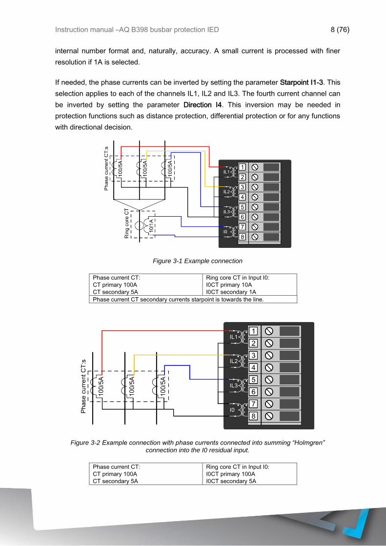
If needed, the phase currents can be inverted by setting the parameter Starpoint I1-3. This
selection applies to each of the channels IL1, IL2 and IL3. The fourth current channel can
be inverted by setting the parameter Direction I4. This inversion may be needed in
protection functions such as distance protection, differential protection or for any functions
with directional decision.
Figure 3-1 Example connection
Phase current CT:
CT primary 100A
CT secondary 5A
Ring core CT in Input I0:
I0CT primary 10A
I0CT secondary 1A
Phase current CT secondary currents starpoint is towards the line.
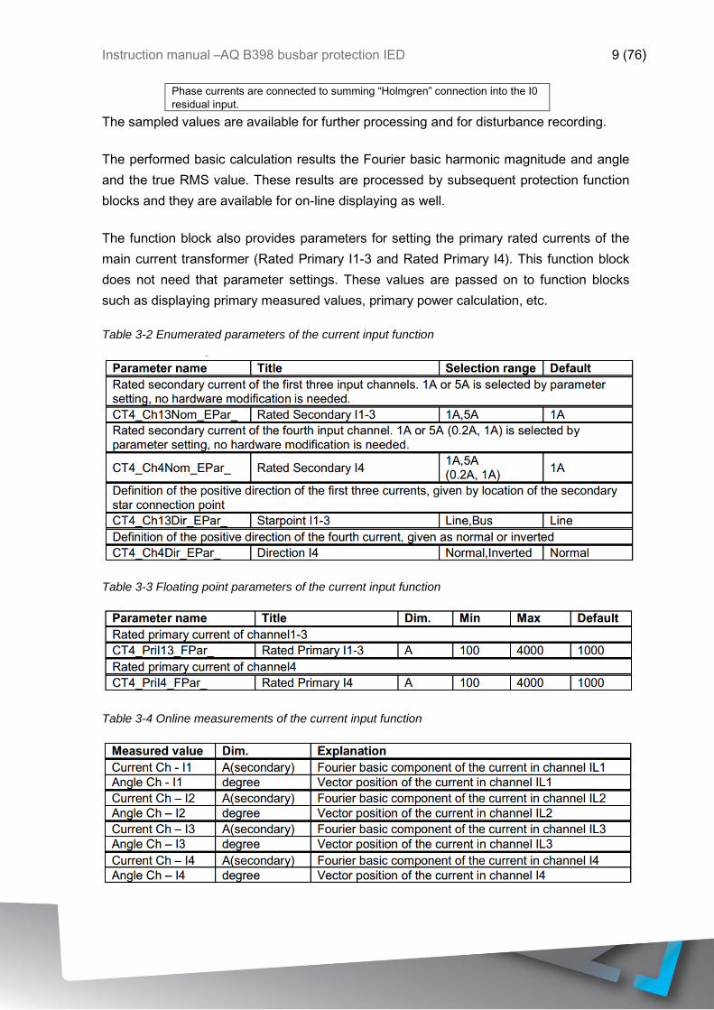
Figure 3-2 Example connection with phase currents connected into summing “Holmgren” connection into the I0 residual input.
Phase current CT:
CT primary 100A
CT secondary 5A
Ring core CT in Input I0:
I0CT primary 100A
I0CT secondary 5A
Instruction manual –AQ B398 busbar protection IED 9 (76)
Phase currents are connected to summing “Holmgren” connection into the I0
residual input.
The sampled values are available for further processing and for disturbance recording.
The performed basic calculation results the Fourier basic harmonic magnitude and angle
and the true RMS value. These results are processed by subsequent protection function
blocks and they are available for on-line displaying as well.
The function block also provides parameters for setting the primary rated currents of the
main current transformer (Rated Primary I1-3 and Rated Primary I4). This function block
does not need that parameter settings. These values are passed on to function blocks
such as displaying primary measured values, primary power calculation, etc.
Table 3-2 Enumerated parameters of the current input function
Table 3-3 Floating point parameters of the current input function
Table 3-4 Online measurements of the current input function
Instruction manual –AQ B398 busbar protection IED 10 (76)
NOTE1: The scaling of the Fourier basic component is such that if pure sinusoid 1A RMS
of the rated frequency is injected, the displayed value is 1A. The displayed value does not
depend on the parameter setting values “Rated Secondary”.
NOTE2: The reference of the vector position depends on the device configuration. If a
voltage input module is included, then the reference vector (vector with angle 0 degree) is
the vector calculated for the first voltage input channel of the first applied voltage input
module. If no voltage input module is configured, then the reference vector (vector with
angle 0 degree) is the vector calculated for the first current input channel of the first
applied current input module. (The first input module is the one, configured closer to the
CPU module.)
3.1.2 VOLTAGE MEASUREMENT AND SCALING
If the factory configuration includes a voltage transformer hardware module, the voltage
input function block is automatically configured among the software function blocks.
Separate voltage input function blocks are assigned to each voltage transformer hardware
module.
A voltage transformer hardware module is equipped with four special intermediate voltage
transformers. As usual, the first three voltage inputs receive the three phase voltages
(UL1, UL2, UL3), the fourth input is reserved for zero sequence voltage or for a voltage
from the other side of the circuit breaker for synchro switching.
The role of the voltage input function block is to
• set the required parameters associated to the voltage inputs,
• deliver the sampled voltage values for disturbance recording,
• perform the basic calculations
o Fourier basic harmonic magnitude and angle,
o True RMS value;
• provide the pre-calculated voltage values to the subsequent software modules,
• deliver the calculated basic Fourier component values for on-line displaying.
The voltage input function block receives the sampled voltage values from the internal
operating system. The scaling (even hardware scaling) depends on a common parameter
“Range” for type selection. The options to choose from are 100V or 200V, no hardware
modification is needed. A small voltage is processed with finer resolution if 100V is
selected. This parameter influences the internal number format and, naturally, accuracy.
Instruction manual –AQ B398 busbar protection IED 11 (76)
There is a correction factor available if the rated secondary voltage of the main voltage
transformer (e.g. 110V) does not match the rated input of the device. The related
parameter is “VT correction“. As an example: if the rated secondary voltage of the main
voltage transformer is 110V, then select Type 100 for the parameter “Range” and the
required value to set here is 110%.
The connection of the first three VT secondary windings must be set to reflect actual
physical connection of the main VTs. The associated parameter is “Connection U1-3“. The
selection can be: Ph-N, Ph-Ph or Ph-N-Isolated.
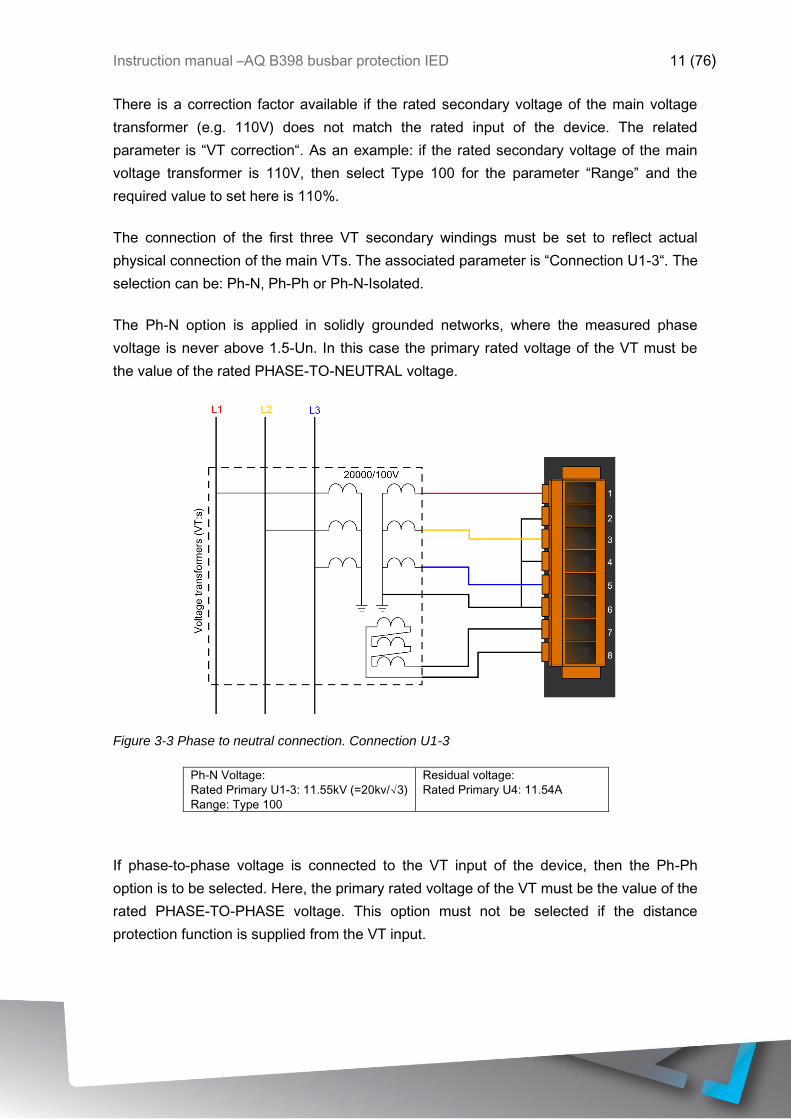
The Ph-N option is applied in solidly grounded networks, where the measured phase
voltage is never above 1.5-Un. In this case the primary rated voltage of the VT must be
the value of the rated PHASE-TO-NEUTRAL voltage.
Figure 3-3 Phase to neutral connection. Connection U1-3
Ph-N Voltage:
Rated Primary U1-3: 11.55kV (=20kv/√3)
Range: Type 100
Residual voltage:
Rated Primary U4: 11.54A
If phase-to-phase voltage is connected to the VT input of the device, then the Ph-Ph
option is to be selected. Here, the primary rated voltage of the VT must be the value of the
rated PHASE-TO-PHASE voltage. This option must not be selected if the distance
protection function is supplied from the VT input.
Instruction manual –AQ B398 busbar protection IED 12 (76)
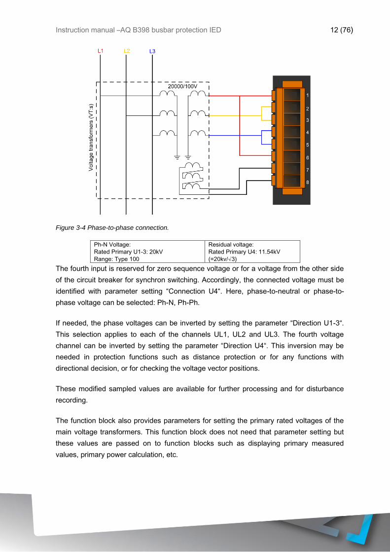
Figure 3-4 Phase-to-phase connection.
Ph-N Voltage:
Rated Primary U1-3: 20kV
Range: Type 100
Residual voltage:
Rated Primary U4: 11.54kV
(=20kv/√3)
The fourth input is reserved for zero sequence voltage or for a voltage from the other side
of the circuit breaker for synchron switching. Accordingly, the connected voltage must be
identified with parameter setting “Connection U4“. Here, phase-to-neutral or phase-to-
phase voltage can be selected: Ph-N, Ph-Ph.
If needed, the phase voltages can be inverted by setting the parameter “Direction U1-3“.
This selection applies to each of the channels UL1, UL2 and UL3. The fourth voltage
channel can be inverted by setting the parameter “Direction U4“. This inversion may be
needed in protection functions such as distance protection or for any functions with
directional decision, or for checking the voltage vector positions.
These modified sampled values are available for further processing and for disturbance
recording.
The function block also provides parameters for setting the primary rated voltages of the
main voltage transformers. This function block does not need that parameter setting but
these values are passed on to function blocks such as displaying primary measured
values, primary power calculation, etc.

Instruction manual –AQ B398 busbar protection IED 13 (76)
Table 3-5 Enumerated parameters of the voltage input function
Table 3-6 Integer parameters of the voltage input function
Table 3-7 Float point parameters of the voltage input function
NOTE: The rated primary voltage of the channels is not needed for the voltage input
function block itself. These values are passed on to the subsequent function blocks.
Table 3-8 On-line measured analogue values of the voltage input function

Instruction manual –AQ B398 busbar protection IED 14 (76)
NOTE1: The scaling of the Fourier basic component is such if pure sinusoid 57V RMS of
the rated frequency is injected, the displayed value is 57V. The displayed value does not
depend on the parameter setting values “Rated Secondary”.
NOTE2: The reference vector (vector with angle 0 degree) is the vector calculated for the
first voltage input channel of the first applied voltage input module. The first voltage input
module is the one, configured closer to the CPU module.
3.2 BUSBAR DIFFERENTIAL PROTECTION FUNCTION
3.2.1 THE BUSBAR REPLICA EVALUATION
The busbar protection algorithm continuously evaluates the status signals of the
disconnectors and if there are changes in the status signals then based on the received
signals the algorithm performs “configuration”, which means determination of the busbar
replica of the substation and an assignment of “Measuring elements” to each
interconnected bus sections.
NOTE: if bus sections are interconnected with each other then only one of the assigned
measuring elements performs the calculation and the results are passed to all other
measuring elements of interconnected bus sections. It means that the on-line displayed
values will be the same for these bus sections.
The busbar protection function performs synchronous sampling of all analog signals.
These values are used by the assigned “Measuring elements” of the busbar protection
functiont. The “Measuring elements” are explained in following chapters.
3.2.2 THE DIFFERENTIAL CURRENT CALCULATION
The method of the differential current calculation is as follows:
▪ Summation of the sampled Ip momentary current values for the bays connected to the
“Measuring element”. The result is the calculated momentary value of the differential current:
= ppd II .
Instruction manual –AQ B398 busbar protection IED 15 (76)
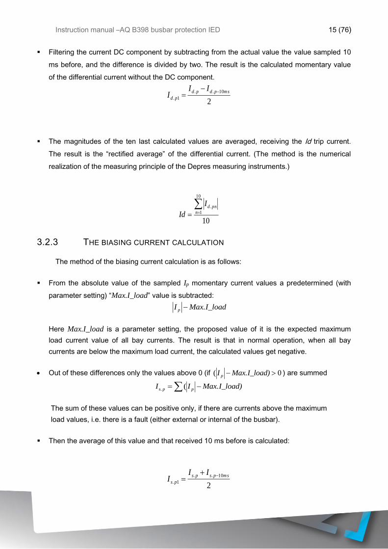
▪ Filtering the current DC component by subtracting from the actual value the value sampled 10
ms before, and the difference is divided by two. The result is the calculated momentary value
of the differential current without the DC component.
2
10..
1.
mspdpd
pd
III
−−=
▪ The magnitudes of the ten last calculated values are averaged, receiving the Id trip current.
The result is the “rectified average” of the differential current. (The method is the numerical
realization of the measuring principle of the Depres measuring instruments.)
10
10
1
.== n
pndI
Id
3.2.3 THE BIASING CURRENT CALCULATION
The method of the biasing current calculation is as follows:
▪ From the absolute value of the sampled Ip momentary current values a predetermined (with
parameter setting) “Max.I_load” value is subtracted:
Max.I_loadI p −
Here Max.I_load is a parameter setting, the proposed value of it is the expected maximum
load current value of all bay currents. The result is that in normal operation, when all bay
currents are below the maximum load current, the calculated values get negative.
• Out of these differences only the values above 0 (if 0( − )Max.I_loadI p ) are summed
−= )Max.I_loadII pps (.
The sum of these values can be positive only, if there are currents above the maximum
load values, i.e. there is a fault (either external or internal of the busbar).
▪ Then the average of this value and that received 10 ms before is calculated:
2
10..
1.
mspsps
ps
III
−+=

Instruction manual –AQ B398 busbar protection IED 16 (76)
▪ The last ten calculated values stored in the memory are averaged, receiving the Is biasing
current:
10
10
1
.== n
pnsI
Is
3.2.4 DIFFERENTIAL CHARACTERISTICS
The trip characteristic for a measuring element is shown in Figure 3-5: Trip characteristic
of the busbar differential protection
Id
Is
Base Sensitivity
k zone
Figure 3-5: Trip characteristic of the busbar differential protection
The setting parameters of the differential characteristics are listed in below table.
Table 3-9: Setting parameters of the differential characteristics
Parameter name Title Unit Min Max Step Default
Percentage characteristic, base sensitivity
Busbar_ZoneSens_IPar_ Base Sensitivity A 100 10000 1 1000
Percentage characteristic, slope*
Busbar_ZoneK_IPar_ k zone* % 40 90 1 80
3.2.5 OFFSET SETTING (“MAX.I_LOAD”)
There are two main requirements for the busbar differential protection:

Instruction manual –AQ B398 busbar protection IED 17 (76)
• In case of busbar fault the operation shall be fast;
• In case of external faults the protection must be stable, no trip command may be generated.
Subtracting the “Max.I_load” value from all current samples serves both these aims. In
normal operation all current samples are expected to be below this setting value, which is
to be the maximum possible current peak value. Consequently in normal operation the
bias current is zero.
If in this state an internal fault occurs then the current samples get very fast above
“Max.I_load” value. Consequently the locus of the Id-Is points on the plane of the
differential characteristics (Figure 3-5) is at once above the line described by the slope “k”
(parameter setting “k_checkzone”). In this case the trip command needs a few checking
points only, the trip command can be fast.
In case of external fault however, the locus of the Id-Is points on the plane of the
differential characteristics (Figure 3-5) start moving in the direction of the Is axis. If the
algorithm recognizes this movement, i.e. the locus is below the line described by the slope
“k” then the number of the required check points gets a high value. This extended
checking period does not permit trip command generation during the time period, when
the iron core of the overloaded current transformer gets saturated, and it cannot deliver
proportional secondary current for the measurement.
3.2.6 VOLTAGE BREAKDOWN CONDITION
In case of current transformer circuit error, the missing current from any of the bays, the
measuring element detects current difference. This could result a trip command to the bus
section. To prevent this kind of operation error, the trip command is released only if in the
affected bus section the voltage collapses.
To perform this supervision, the presence of the voltage is monitored with a quick voltage
measuring function. The result of the supervision is considered in every millisecond. If
before increasing the current, the voltage is in the range of the normal operating voltage
(above approximately 0.6Un), and then during a fault any of the voltages is below 0.6Un,
the function enables the operation of the differential protection function. If the currents
fulfill the differential criteria, the algorithm generates a trip command.
If the differential protection function started and the bay units received trip command then
this voltage condition does not play any role. The trip command resets only if the currents
are outside the tripping zone of the characteristics.

Instruction manual –AQ B398 busbar protection IED 18 (76)
A voltage monitoring function can allow trip command only for 0.5 s, then the function is
disabled until the measured voltage returns to healthy state again, or a new initializing is
performed (caused by disconnector status change, switching on, parameter changes).
If all voltage monitoring functions assigned to a measuring element detect low voltage
then the bus-bar section is considered to be disconnected, and the operation of the bus-
bar differential protection is enabled again (to cover the switch-on-to-fault condition).
If the trip command is disabled by the voltage condition then the “On-line” screen of the
connected PC displays the status signal as “U>disable: +“. If one or more voltage
supervisions detect low voltage then the display changes form “+“ to “-”. At that moment a
0.5s timer is started, and when it expires then the operated voltage supervision function is
disabled. As a consequence the signal shows “+“ again.
The parameters for the voltage breakdown condition are fixed values and the function
does not need any parameter setting.
3.2.7 THE CHECK ZONE
If any of the status signals received from the bays is wrong then the false operation based
on this wrong signal could disconnect the bus section. To avoid this kind of errors the
“check zone” is applied. This additional “check zone measuring element” supposes the
whole busbar system as a single node. It gets all current samples from the bays (except
those sampled from the current transformers connecting bus sections; this is to be
selected in the process of the topology configuration by the user with “Master” access
rights) and adds them all to get the check zone differential current. The individual
measuring elements can generate a trip command only if also the “check zone measuring
element” detects an internal busbar fault. The check zone operation must be enabled by
parameter setting.
The parameters of the “check zone measuring element” are similar to those of the
individual measuring element, but the values can be set independently.
3.2.8 SATURATED WAVEFORM COMPENSATION
In case of external fault, with the exception of the faulty bay, all bays deliver currents
towards the busbar. The sum of these currents flows through the current transformer of
the faulty bay. Consequently this current can be extremely high, which can saturate the

Instruction manual –AQ B398 busbar protection IED 19 (76)
iron core of this current transformer. The shape of this secondary current gets distorted,
and the “missing” section of the wave-shape is a differential current.
To prevent unwanted operation of the busbar differential protection function for these
external faults, there are several remedies. One of them is the “saturated waveform
compensation”. The algorithm “keeps” the detected current peak till the end of the half
period, decreasing the chance for the false trip decision.
This method does not need any special parameter setting.
3.2.9 DIRECTIONALITY CHECK
In case of internal fault all bays deliver currents towards the busbar. In case of external
fault however, with the exception of the faulty bay, all bays deliver currents towards the
busbar, and the current of the faulty bay flows out of the busbar. When considering this
basic difference, the stability of the busbar differential protection can be improved by
“directionality check”.
The busbar differential protection algorithm compares the sign of all current samples in a
“measuring element”. If during the majority of the samples one of the currents shows
opposite sign, indicating opposite direction, then this fact prevents generation of the trip
command.
3.2.10 CURRENT TRANSFORMER FAILURE DETECTION
If the current transformers do not deliver correct currents for the evaluation then the
correct decision of the busbar differential protection is not possible.
The currents are continuously supervised also during normal operation of the system,
when the currents are below the operation level of the differential protection. If in this state
any of the currents is missing then a relatively high differential current is measured (which
is still not sufficient to operate the differential protection). The algorithm performs the
current supervision based on a similar characteristic as the trip characteristic, which has a
sensitive base setting and a given slope. (See also Figure 3-5)
If the measured currents result an Id–Is point above this characteristic, then after a time
delay the “measuring element” gets blocked.

Instruction manual –AQ B398 busbar protection IED 20 (76)
3.2.11 CHECKING THE DISCONNECTOR STATUS SIGNALS
The actual configuration of the busbar (interconnected or separated bus sections and the
connection of the bays to the bus sections) is evaluated using status signals of the
disconnectors. The status of each disconnectors is characterized by dual signals:
“Disconnector open” and “Disconnector closed”. Only one of them can be true and one of
them can be false. This function checks these status signals, and performs the decision
based on parameter setting.
In normal operation when receiving faulty status signals from the disconnectors the device
keeps the previous state for a time period defined by parameter setting. After this time
delay the reaction of the algorithm depends on the setting of the dedicated enumerated
parameter. If the setting of the “BadState Tolerate” is true, then the operation neglects the
faulty status signal, and the last valid status is kept. In case of setting “false”, the
“measuring element” gets blocked.
If the status error is detected after energizing or following parameter changes, the
protection remains disabled until the faulty status is corrected, and generates “Differential
protection disabled” and “Breaker failure disabled” status signals as well.
3.2.12 MEASURED VALUES
For each voltage inputs the device measures and displays the phase voltages. Table 3-10
shows as an example the voltages of a bus section.
Table 3-10: Measured voltages of the centralized busbar differential protection function (example)
Measured value Dim. Explanation
Voltage Ch - U1 (secondary) V Phase voltage L1, Fourier base component
Voltage Ch – U2 (secondary) V Phase voltage L2, Fourier base component
Voltage Ch – U3 (secondary) V Phase voltage L3, Fourier base component
For each bays the device measures and displays the phase currents. Table 3-11 shows
as an example the currents of a bay.
Table 3-11: Measured phase currents of the centralized busbar differential protection function (example)

Instruction manual –AQ B398 busbar protection IED 21 (76)
Measured value Dim. Explanation
Current Ch - I1 (secondary) A Phase current L1, Fourier base component
Angle Ch - I1 deg Phase angle of the current in L1
Current Ch – I2 (secondary) A Phase current L2, Fourier base component
Angle Ch – I2 deg Phase angle of the current in L2
Current Ch – I3 (secondary) A Phase current L3, Fourier base component
Angle Ch – I3 deg Phase angle of the current in L3
For each bus sections the device measures and displays the differential currents and the
bias currents. Table 3-12 shows as an example the currents of a bus section. (If the bus
sections are interconnected with each other then the displayed values are the same of the
interconnected sections.)
Table 3-12: Measured differential currents of the centralized busbar differential protection function
(example)
Measured value Dim. Explanation
I Diff L1 (primary) A Differential current L1, Fourier base component
I Diff L2 (primary) A Differential current L2, Fourier base component
I Diff L3 (primary) A Differential current L3, Fourier base component
I Bias L1 (primary) A Bias current L1, Fourier base component
I Bias L2 (primary) A Bias current L2, Fourier base component
I Bias L3 (primary) A Bias current L3, Fourier base component
Note: The evaluated basic harmonic values of the measured input phase currents help the
commissioning of the busbar differential protection function. The reference quantity of the
per unit values is the rated current of the current input.
3.2.13 BEHAVIOR OF THE ALGORITHM IN INTERNAL FAULT
For an internal bus-bar fault the measuring principle can be seen in Figure 3-2.
Instruction manual –AQ B398 busbar protection IED 22 (76)
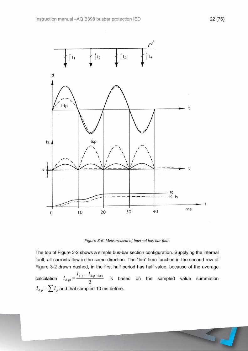
Figure 3-6: Measurement of internal bus-bar fault
The top of Figure 3-2 shows a simple bus-bar section configuration. Supplying the internal
fault, all currents flow in the same direction. The “Idp” time function in the second row of
Figure 3-2 drawn dashed, in the first half period has half value, because of the average
calculation 2
10..
1.
mspdpd
pd
III
−−= is based on the sampled value summation
= ppd II . and that sampled 10 ms before.
Instruction manual –AQ B398 busbar protection IED 23 (76)
The “Isp” time function in the third row of Figure 3-2, drawn dashed, in the first half period
has half value too, because of the average calculation 2
10..
1.
mspsps
ps
III
−+= , based on the
calculation mentioned before: −= )Max.I_loadII pps (. , if ( 0− )Max.I_loadI p ),
and because in normal operation these values are continuously zero, as the “a” load
current value is continuously subtracted.
The bottom curve in Figure 3-2 shows Id and K*Is, which is the result of averaging 10
values:
10
10
1
.== n
pndI
Id and 10
**
10
1
.== n
pnsI
KIsK .
As before fault both Id and K*Is are zero the bottom curves in Figure 3-2 increase step-by-
step. In the evaluation there is no intentional time delay or measured value exclusion.
Tripping is generated after 8 consecutive starting of the function. In case of internal fault
as Figure 3-2 shows, Id is continuously above K*Is, and after 8 comparisons the
measuring element automatically generates trip command. The command detected on the
output relay is somewhat delayed because of the operating time of the relay. The duration
of the trip impulse is at least 500ms, the algorithm resets the command only after this time
delay, if the conditions are reset meantime. The drop-off ratio of the trip current is 1.
3.2.14 BEHAVIOR OF THE ALGORITHM IN EXTERNAL FAULT
Figure 3-7 below shows the calculation of the bias and differential currents for an external
fault in case of heavy current transformer saturation.

Instruction manual –AQ B398 busbar protection IED 24 (76)
.
„Iload”
Figure 3-7: Measurement of external bus-bar fault
The top of Figure 3-7 shows a simple bus-bar section configuration, where Bay 4 has an
external fault. The currents in the healthy bays flow in the same direction, the fault current
in Bay 4 is the sum of these currents, and flows in inverse direction. Because of
concentrated fault current the CT in Bay 4 can be saturated. The first curves of Figure 3-7
show that opposite to the sum of the healthy bay current (I1+I2+I3) the I4 bay current is
not exactly the inverse, some current samples are “missing” as caused by the distortion of

Instruction manual –AQ B398 busbar protection IED 25 (76)
the saturation. (Figure 3-7 shows “ideal” saturation!). In calculation of Idp, this “missing”
current section is detected (dashed line)
The third section of Figure 3-7 shows the calculated Isp (dashed line too). It is clearly
seen that the biasing current increases immediately, and because of the saturation the
increasing is slowed down only at the end of the first half period. Of course in the first half
period the values are halved, as in case of internal fault.
As the fourth section of Figure 3-7 shows the summed K*Is biasing current is continuously
above Id. So in case of K=0.8 the comparison performed in each millisecond never cause
operation of the differential protection function.
Based on Figure 3-7 the limits of the measuring principle of the algorithm can be
explained:
Let’s suppose that the current transformer of the faulty bay saturates at IT current, and that
the current transformer cannot deliver secondary current in saturated state (“ideal
saturation”).
If the sum of the currents on healthy bays is Izm (this is the maximal fault current, when
the protection operates correctly), in the faulty bay it is only IT (less than the fault current)
then the trip current is:
TIIzmId −= .
The biasing current is with similar procedure:
]*)[(** Max.I_loadnIIzmKIsK T −+=
where n is the number of the bays,
Max.I_load is the subtracted load current value.
In the following explanation Max.I_load =0 setting value is supposed.
The trip equation is:
IsKId *
which yields with substitution of the expressions above:
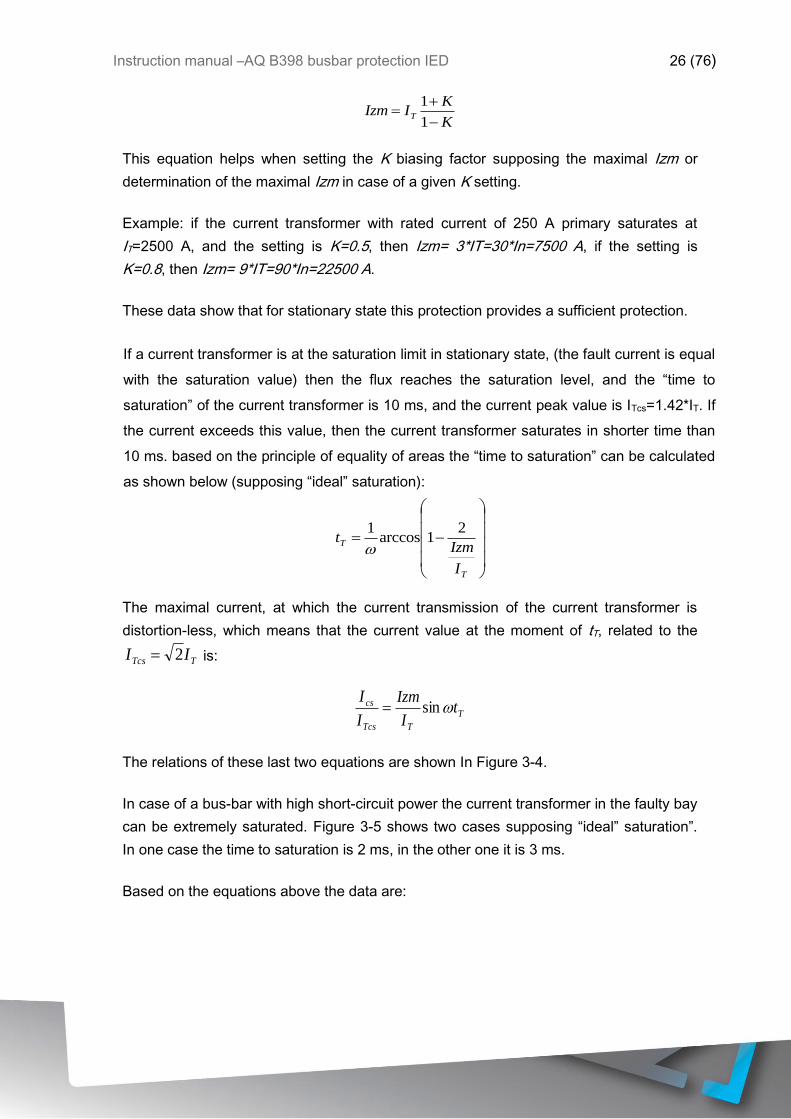
Instruction manual –AQ B398 busbar protection IED 26 (76)
K
KIIzm T
−
+=
1
1
This equation helps when setting the K biasing factor supposing the maximal Izm or
determination of the maximal Izm in case of a given K setting.
Example: if the current transformer with rated current of 250 A primary saturates at
IT=2500 A, and the setting is K=0.5, then Izm= 3*IT=30*In=7500 A, if the setting is
K=0.8, then Izm= 9*IT=90*In=22500 A.
These data show that for stationary state this protection provides a sufficient protection.
If a current transformer is at the saturation limit in stationary state, (the fault current is equal
with the saturation value) then the flux reaches the saturation level, and the “time to
saturation” of the current transformer is 10 ms, and the current peak value is ITcs=1.42*IT. If
the current exceeds this value, then the current transformer saturates in shorter time than
10 ms. based on the principle of equality of areas the “time to saturation” can be calculated
as shown below (supposing “ideal” saturation):
−=
T
T
I
Izmt
21arccos
1
The maximal current, at which the current transmission of the current transformer is
distortion-less, which means that the current value at the moment of tT, related to the
TTcs II 2= is:
T
TTcs
cs tI
Izm
I
Isin=
The relations of these last two equations are shown In Figure 3-4.
In case of a bus-bar with high short-circuit power the current transformer in the faulty bay
can be extremely saturated. Figure 3-5 shows two cases supposing “ideal” saturation”.
In one case the time to saturation is 2 ms, in the other one it is 3 ms.
Based on the equations above the data are:

Instruction manual –AQ B398 busbar protection IED 27 (76)
for 5=TI
Izm tT=3 ms and 4=
Tcs
cs
I
I
for 10=TI
Izm tT=2 ms and 6=
Tcs
cs
I
I
Figure 3-8: Time to saturation and the maximal transmitted current as the function of the fault current

Instruction manual –AQ B398 busbar protection IED 28 (76)
In case of external fault, even if the time to saturation is below 2 ms, there can be a
considerable time span, when Id>K*Is (see Figure 3-6). If this time is more than 8 ms,
then the measuring element generates a false trip command for external fault. This can
occur in case of high grade of transient saturation.
Figure 3-9: External fault causing extreme saturation (supposing „ideal saturation”)
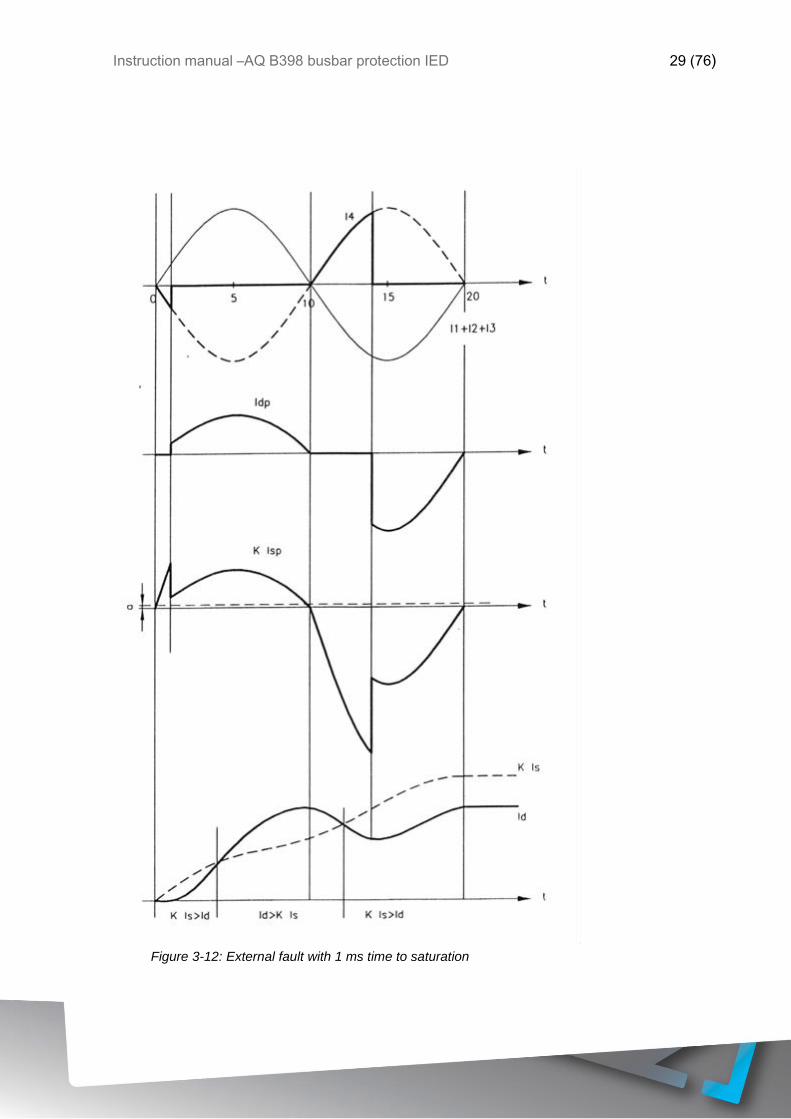
Instruction manual –AQ B398 busbar protection IED 29 (76)
Figure 3-12: External fault with 1 ms time to saturation

Instruction manual –AQ B398 busbar protection IED 30 (76)
To avoid false trip command in case of external fault the algorithm uses the following
method. As it can be seen in Figure 3-6, at the beginning the biasing current is always
above the trip current, and in this time the measuring element blocks the trip command.
This blocking can never occur in case of internal fault, so in case of initial blocking it can
be always supposed that the fault is an external fault. So if the biasing current is above
the tripping current even in one step, then the measuring element switches over from 8 to
25 for the count limit of tripping conditions (the duration is in this case 25 ms). This
method assures correct operation in case of extreme saturation as well.
The application of the method above does not result increasing operating time in case of
internal fault, because the 25 times checking can occur only for external faults. The only
exception is the “transition” of the fault location, when a close external fault evolves to
internal fault. In this special case the operation can be expected only after a 25 ms time
delay, but this method increases stability for external faults.
To avoid false tripping the algorithm applies an additional safety method. All bay units of
the busbar differential protection system monitor in all three phases the increasing and
decreasing periods of the bay currents. If in a bay the current increases, subsequently
decreases within 3 ms, then the protection algorithm keeps the last high value up to the
end of the half period. This method supplies at least partly the missing current samples,
and at the same time no excess in biasing current can occur, because this curve shape
results the same current value as the unsaturated one if the time span is 2 ms, and about
the half value if the time span is 1 ms. (See Figure 3-6).
This method results suitable biasing and a small Id value, which assures stability for
stationary external faults even in case of 40 times saturation current (e.g. for n=10 this
means 10*40=400 times rated current).
This explanation proves the use of the method keeping the last high value up to the end of
the half period.
It has to be mentioned that even in extreme cases the method of changing the number of
checking from 8 to 25 can prevent false tripping with high reliability. As the result of the
application of the methods explained above the operation of the protection is reliable in
case of extreme stationary saturation and for high residual flux value as well. The only
requirement of the protection is tT1 ms minimal time to saturation (the time span, when
the current transition is distortion-less).
Instruction manual –AQ B398 busbar protection IED 31 (76)
The bus-bar differential protection measures in all three phases, but the trip command is
generated common for all three phases of the circuit breaker.
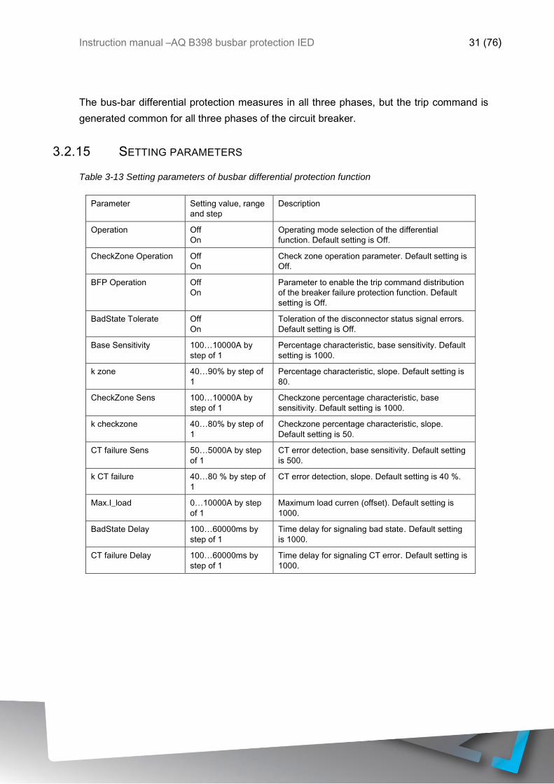
3.2.15 SETTING PARAMETERS
Table 3-13 Setting parameters of busbar differential protection function
Parameter Setting value, range
and step
Description
Operation Off
On
Operating mode selection of the differential
function. Default setting is Off.
CheckZone Operation Off
On
Check zone operation parameter. Default setting is
Off.
BFP Operation Off
On
Parameter to enable the trip command distribution
of the breaker failure protection function. Default
setting is Off.
BadState Tolerate Off
On
Toleration of the disconnector status signal errors.
Default setting is Off.
Base Sensitivity 100…10000A by
step of 1
Percentage characteristic, base sensitivity. Default
setting is 1000.
k zone 40…90% by step of
1
Percentage characteristic, slope. Default setting is
80.
CheckZone Sens 100…10000A by
step of 1
Checkzone percentage characteristic, base
sensitivity. Default setting is 1000.
k checkzone 40…80% by step of
1
Checkzone percentage characteristic, slope.
Default setting is 50.
CT failure Sens 50…5000A by step
of 1
CT error detection, base sensitivity. Default setting
is 500.
k CT failure 40…80 % by step of
1
CT error detection, slope. Default setting is 40 %.
Max.I_load 0…10000A by step
of 1
Maximum load curren (offset). Default setting is
1000.
BadState Delay 100…60000ms by
step of 1
Time delay for signaling bad state. Default setting
is 1000.
CT failure Delay 100…60000ms by
step of 1
Time delay for signaling CT error. Default setting is
1000.

Instruction manual –AQ B398 busbar protection IED 32 (76)
Table 3-14: Bay related setting parameters
Parameter Setting value, range
and step
Description
Bay disable 0 enabled
1 disabled
Disabling the bay (e.g during maintenance). Default
setting is 0.
Rated secondary 1A
5A
CT secondary rated current. Default setting is 1A.
Star point I1-3 Line
Bus
Location of the CT star point. Default setting is
Line.
CT nominal 100…10000A by
step of 1
CT primary rated current. Default setting is 1000.
BFP operation Off
On
Enabling the bay to be part of breaker failure
protection scheme. Default setting is Off.
Table 3-15: Breaker failure protection related setting parameters
Parameter Setting value, range
and step
Description
Start Ph Current 20..200 % by step of
1
Current condition for the breaker failure protection
function. Default setting is 30.
Backup Time Delay 60…1000ms by step
of 1
Breaker failure time delay setting. Default setting is
200.
Pulse Duration 0…60000ms by step
of 1
Breaker failure pulse duration. Default setting is
100.
Intertrip operation * Off,On Parameter to enable the trip command distribution
of the breaker failure protection function
*only in distributed version
Table 3-16: Voltage breakdown parameters
Parameter Setting value, range
and step
Description
Voltage check Fixed setting 0.6xUn Voltage breakdown criteria. Fixed setting is 0.6xUn.

Instruction manual –AQ B398 busbar protection IED 33 (76)
3.3 BREAKER FAILURE PROTECTION FUNCTION
The breaker failure protection utilizes the processed status information of the busbar
protection to disconnect only the section of the busbar to which the faulty circuit breaker is
connected. So the other zones can remain in continuous service, fulfilling the same
requirement as the busbar differential protection does.
The starting of the breaker failure protection is received on dedicated binary input
channels. For operation the current of the bay must be above the level, as set bay an
integer parameter value. Also the time delay of the function is a parameter value. The
duration of the pulse can be set
Based on the status signals of the disconnectors, the algorithm selects all bays, which are
interconnected with the bay announcing breaker failure. Accordingly only the minimum
number of the bays gets the trip command, the other bus-sections remain in continuous
operation.
3.3.1 FUNCTION BLOCK SYMBOL
Figure 3-13: Function block of the breaker failure protection function in centralized busbar protection
version
Figure 3-14: Function block of the breaker failure protection function in distributed busbar protection bay
units

Instruction manual –AQ B398 busbar protection IED 34 (76)
The function block shown in Figure 3-14 is identical to bay unit device circuit breaker
failure protection block, for details of its function refer to related bay unit device instruction
manual.

Instruction manual –AQ B398 busbar protection IED 35 (76)
4 BUSBAR DIFFERENTIAL PROTECTION VARIANTS
The AQ 398 comes in two alternative configurations, either as centralized busbar
protection or as distributed (de-centralized) busbar protection. In both configurations the
AQ B398 provides three phase biased low impedance type of bus-bar differential
protection and circuit breaker failure protection functions. The protection algorithm is
identical in both configurations. The difference between the configurations is that in
distributed system the bay related information is transferred to AQ B398 unit from bay
units via fiber optic links whereas in centralized system the bay information is wired
directly to AQ B398 unit.
4.1 DISTRIBUTED BUSBAR PROTECTION
When the AQ B398 is configured as a master unit of a distributed busbar protection
system the busbar protection system operation is based on high speed optical fibre cable
communication between the AQ B398 master unit and bay units. AQ 300 series protection
IEDs can be utilized as bay units. The central unit performs bus section selective
protection based on the information received from the bay units. The circuit breaker failure
protection is activated by AQ B398 unit in case of failure in opening of the circuit breaker.
The distributed busbar protection system consists of one central unit, AQ B398 and one
bay unit for each bay. The bay unit can be an AQ 300 series distance protection,
transformer protection or an overcurrent protection IED with incorporated busbar
protection bay unit feature. All bay units are interconnected with the central unit via high-
speed serial fibre optic cable pairs.
The bay units send to the central unit the following information:
- the current values of each phase sampled with 1 ms time intervals
- presence or absence of the three phase voltages
- the status of bus disconnecting switches of the bay using two bit status signals
- starting command for the bay breaker failure protection
- trip signals
The central unit sends to the bay units the following information:
- synchronizing signal with 1 ms time intervals
- trip command, when protection activates

Instruction manual –AQ B398 busbar protection IED 36 (76)
The central unit determines the busbar configuration based on the signals received via
fibre optic communication links and assigns measuring elements to the bus sections. The
measuring elements are used to determine the sum of the currents (current difference)
and to calculate the biasing current based on the current magnitudes. The differential
protection is based on the characteristics with a single knee point. The AQ B398 decision
logic guarantees the correct operation even in case of high CT saturation. In order to
issue the trip command the voltage breakdown condition must be fulfilled as well (voltage
drop in faulty busbar and affected phase).
The breaker failure protection has two steps. The first step generates a repeat trip
command to the selected bay unit’s circuit breakers both trip coils and the second step
issues a general trip command to all circuit breakers.
4.2 CENTRALIZED BUSBAR DIFFERENTIAL PROTECTION
In centralized configurations all the bay current transformer inputs, bus section voltage
transformer inputs and switching status inputs are wired directly to AQ 398 unit. The
selected hardware configuration depends on the number of bays connected to the system
(for more details refer to section 4.2.1). The AQ 398 performs bus section selective
protection based on the information wired directly to the unit. The circuit breaker failure
protection is activated by AQ B398 unit in case of failure in opening of the circuit breaker.
The centralized busbar protection unit determines the busbar configuration based on the
wired status signals. The measuring elements are used to determine the sum of the
currents (current difference) and to calculate the biasing current based on the current
magnitudes. The differential protection is based on the characteristics with a single knee
point. The AQ B398 decision logic guarantees the correct operation even in case of high
CT saturation. In order to issue the trip command the voltage breakdown condition must
be fulfilled as well (voltage drop in faulty busbar and affected phase).
The breaker failure protection has two steps. The first step generates a repeat trip
command to the selected bay unit’s circuit breakers both trip coils and the second step
issues a general trip command to all circuit breakers.
4.2.1 CENTRALIZED BUSBAR PROTECTION HARDWARE CONFIGURATIONS
Here different variants for centralized busbar differential protection configurations are
presented. The maximum configuration in one AQ B398 unit contains six current
transformer input cards and two voltage transformer input cards. This means that

Instruction manual –AQ B398 busbar protection IED 37 (76)
maximum 3-phase protection configuration is for six bays and two busbar sections. If
more than six bays and/or two busbar sections are to be protected three AQ B398 units
are needed, each in a single-phase configuration.
All configurations contain eight high speed trip outputs, 48 digital status inputs and 16
digital outputs. Communication options are in the CPU card. Optionally a redundant power
supply may be utilized.
The hardware variant in Figure 4-1 contains three current transformer input cards and one
voltage transformer input card. This variant can be utilized for 3-phase busbar differential
protection of maximum three bays and one busbar section. Alternatively this unit can be
used for 12 single phase bays and four single phase bus sections.
Figure 4-1: Hardware variant of three CT cards and one VT card
The hardware variant in Figure 4-2 contains four current transformer input cards and one
voltage transformer input card. This variant can be utilized for 3-phase busbar differential
protection of maximum four bays and one busbar section. Alternatively this unit can be
used for 16 single phase bays and four single phase bus sections.
Figure 4-2: Hardware variant of four CT cards one VT card
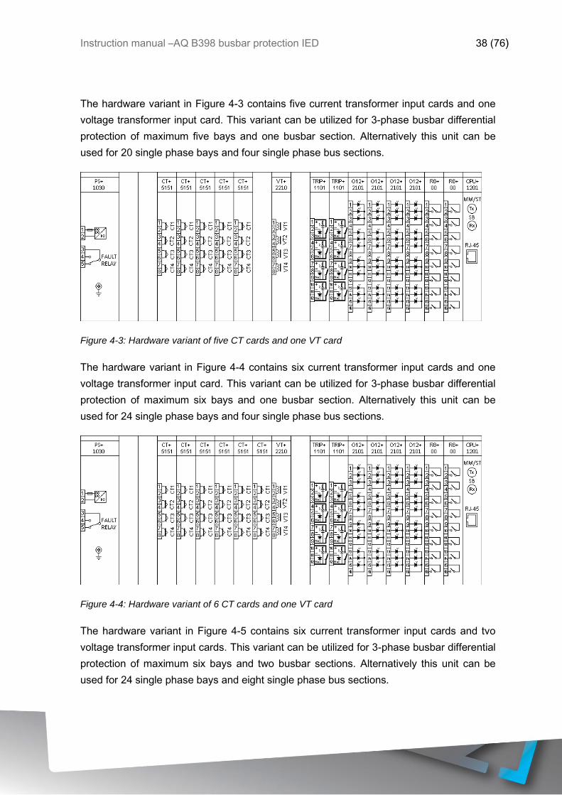
Instruction manual –AQ B398 busbar protection IED 38 (76)
The hardware variant in Figure 4-3 contains five current transformer input cards and one
voltage transformer input card. This variant can be utilized for 3-phase busbar differential
protection of maximum five bays and one busbar section. Alternatively this unit can be
used for 20 single phase bays and four single phase bus sections.
Figure 4-3: Hardware variant of five CT cards and one VT card
The hardware variant in Figure 4-4 contains six current transformer input cards and one
voltage transformer input card. This variant can be utilized for 3-phase busbar differential
protection of maximum six bays and one busbar section. Alternatively this unit can be
used for 24 single phase bays and four single phase bus sections.
Figure 4-4: Hardware variant of 6 CT cards and one VT card
The hardware variant in Figure 4-5 contains six current transformer input cards and tvo
voltage transformer input cards. This variant can be utilized for 3-phase busbar differential
protection of maximum six bays and two busbar sections. Alternatively this unit can be
used for 24 single phase bays and eight single phase bus sections.

Instruction manual –AQ B398 busbar protection IED 39 (76)
Figure 4-5: Hardware variant of six CT cards and two VT card
4.3 GENERIC BUSBAR PROTECTION APPLICATION EXAMPLE
The figure below shows a generic connection example of the busbar protection system
described in single phase connection.
Figure 4-6: Generic busbar protection application example

Instruction manual –AQ B398 busbar protection IED 40 (76)
4.4 BUSBAR DIFFERENTIAL PROTECTION SOFTWARE CONFIGURATION
The behavior of the busbar differential protection is determined by the configuration and
the algorithm and related parameter setting.
4.4.1 FUNCTION BLOCKS
The busbar protection related functions blocks are as described in following chapters.
Both centralized and distributed busbar protection function blocks are explained.
4.4.1.1 Busbar function block
The busbar function block performs the organization of the busbar protection system, and
also the numerical calculations and decisions are performed in this module. Based on the
disconnector status information received from the bus sections “Measuring elements” are
composed. A “Measuring element” processes all currents, which are flowing into or out of
the interconnected bus sections. Accordingly the number of the processed “Measuring
elements” can be the number of the individual bus sections, as a maximum; or there can be
less “Measuring elements”, if some bus sections are interconnected with each other.
The busbar protection function always contains one “Busbar” function block. Its task is
also to process the parameters of the busbar protection function. The symbol of the
“Busbar” function block, as it appears in the AQtivate 300 software, is as follows.
Figure 4-7: Busbar function block in centralized busbar protection version
Figure 4-8 Busbar function block in distributed busbar protection version
Instruction manual –AQ B398 busbar protection IED 41 (76)
Table 4-1: The binary input status signals of the centralized busbar differential protection function, central
SW module
Binary input signals Signal title Explanation
Busbar_BBPBlock_GrO_ BBP Block Blocking the busbar differential protection function
Busbar_BFPBlock_GrO_ BFP Block Blocking the breaker failure protection function
Table 4-2: The binary output status signals of the centralized busbar differential protection
function, central SW module
Binary output signals Signal title Explanation
Busbar_Blocked_GrI_ Blocked The busbar protection is in blocked state
Busbar_DCError_GrI_ DC Error Disconnector status error
Com fail signal in distributed busbar protection version indicates communication failure to bay unit(s).
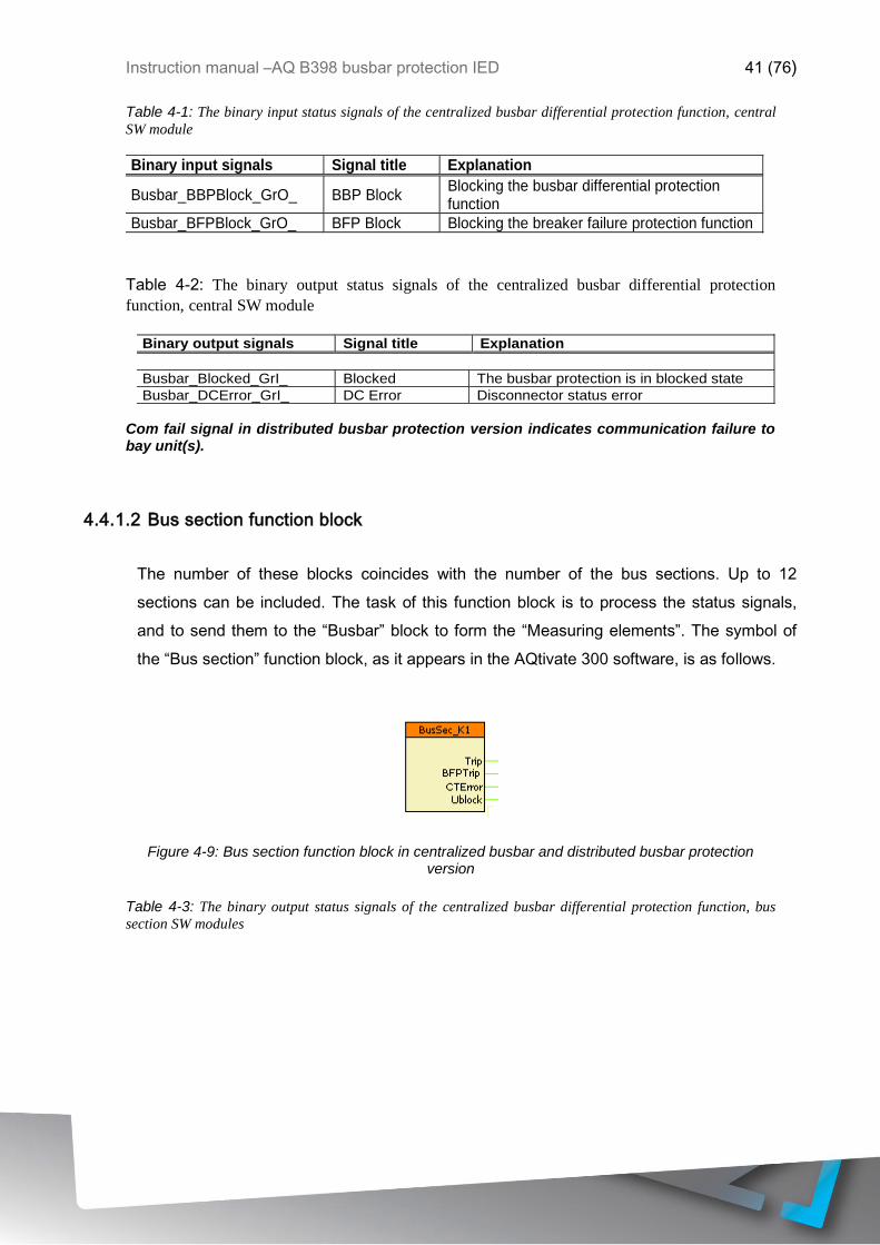
4.4.1.2 Bus section function block
The number of these blocks coincides with the number of the bus sections. Up to 12
sections can be included. The task of this function block is to process the status signals,
and to send them to the “Busbar” block to form the “Measuring elements”. The symbol of
the “Bus section” function block, as it appears in the AQtivate 300 software, is as follows.
Figure 4-9: Bus section function block in centralized busbar and distributed busbar protection version
Table 4-3: The binary output status signals of the centralized busbar differential protection function, bus
section SW modules

Instruction manual –AQ B398 busbar protection IED 42 (76)
Binary output signals Signal title Explanation
BusSec_TripL1_GrI__M01* Trip L1* L1 trip signal for the bus section
BusSec_TripL2_GrI__M01* Trip L2* L1 trip signal for the bus section
BusSec_TripL3_GrI__M01* Trip L3* L1 trip signal for the bus section
BusSec_Trip_GrI__M01 Trip General trip command for the bus section
BusSec_BFPTrip_GrI__M01 BFP Trip Trip command generated by the breaker failure protection function
BusSec_CTError_GrI__M01 CT Error Error in current measurement
BusSec_Ublock_GrI__M01 U block The differential protection is blocked by voltage condition
* Valid in three-pole version only
4.4.1.3 Bay unit function block
The number of these blocks coincides with the number of the bays in the substation. The
task of this block is to receive and process all information from the primary devices of the
bay:
o Currents (Three phase currents or one phase current, depending of the selected
option)
o Voltages (Three phase voltages or one phase voltage, depending of the selected
option)
o Status signals of the disconnectors: these signals are received with dual signals
(disconnector open and diconnector closed). Up to 4 disconnectors can be
configured to a physical bay.
This block passes the trip command to the circuit breaker of the bay.
This block also inputs the breaker failure signal from the bay protection units, and
information related to the “stub” protection. The blocking input signal received by this bay
unit disables the operation of the “Measuring element”, to which this bay is dynamically
assigned.

Instruction manual –AQ B398 busbar protection IED 43 (76)
Figure 4-10: Bay unit function block in centralized busbar protection version
Figure 4-11 Bay unit function block in distributed busbar protection mater unit
Table 4-4: The binary input status signals of the centralized busbar differential protection function, bay unit
SW modules
Binary input signals Signal title Explanation
BayUnit_BFPTrip_GrO_ BFP Trip
Breaker failure signal from the protection of the bay. The breaker failure protection passes this signal to all bays of the interconnected bus sections, related to this particular bay
BayUnit_DC1Close_GrO_ DC1 Close Disconnector 1 in closed state
BayUnit_DC1Open_GrO_ DC1 Open Disconnector 1 in open state
BayUnit_DC2Close_GrO_ DC2 Close Disconnector 2 in closed state
BayUnit_DC2Open_GrO_ DC2 Open Disconnector 2 in open state
BayUnit_DC3Close_GrO_ DC3 Close Disconnector 3 in closed state
BayUnit_DC3Open_GrO_ DC3 Open Disconnector 3 in open state
BayUnit_DC4Close_GrO_ DC4 Close Disconnector 4 in closed state
BayUnit_DC4Open_GrO_ DC4 Open Disconnector 4 in open state
BayUnit_ForceZero_GrO_* Force Zero* In TRUE state of this input signal the bay unit sends zero value as the sampled current
BayUnit_BlkSect_GrO_ Blk Sect In TRUE state of this input signal the measuring element related to this bay gets in blocked state
*NOTE: In bay units without CT this parameter is missing

Instruction manual –AQ B398 busbar protection IED 44 (76)
Table 4-5: The binary output status signals of the centralized busbar differential protection function, bay
unit SW modules
Binary output signals Signal title Explanation
BayUnit1f_DCErr_GrI__T1 DC Error Disconnector error
BayUnit1f_Trip_GrI__T1 Trip Trip command to the circuit breaker of the bay
BayUnit_BayDisable_GrI__B1U Bay disabled Bay disabled
4.4.1.4 Sectionalizer function block
These blocks serve mapping the sectionalizer bays, the bays which interconnect bus
sections with disconnectors. These blocks receive up to two disconnector status signals.
Figure 4-12: Sectionalizer function block in centralized busbar and distributed busbar protection version
Table 4-6: The binary input status signals of the centralized busbar differential protection function,
sectionalizer SW modules
Binary input signals Signal title Explanation
SecStat_DC1Close_GrO_ DC1 Close Disconnector 1 in closed state
SecStat_DC1Open_GrO_ DC1 Open Disconnector 1 in open state
SecStat_DC2Close_GrO_ DC2 Close Disconnector 2 in closed state
SecStat_DC2Open_GrO_ DC2 Open Disconnector 2 in open state
Table 4-7: The binary output status signals of the centralized busbar differential protection function,
sectionalizer SW modules
Binary output signals Signal title Explanation
SecStat_StatErr_GrI__K Status Error Status signal error
SecStat_SectClosed_GrI__K Sect. Closed Closed state of the sectionalizer
4.4.1.5 Busbar bay unit function block
This block is applied only in the distributed busbar protection system and it is the “interface”
between the power technology (measuring transformers, disconnector status signals, and

Instruction manual –AQ B398 busbar protection IED 45 (76)
circuit breaker trip commands) and the busbar protection function in the central device. In the
bay device it receives the disconnector status information, the breaker failure signal from the
protection function (according to the graphic assignment), and a special signal to exclude the
measurements from the evaluation.
If the bay protection is to be involved in the busbar protection scheme, this function block is
mandatory. The busbar protection function always contains one “Busbar” function block. Its
task is also to process the parameters of the busbar protection configuration. The symbol of
the “Busbar bay unit” function block, as it appears in the AQtivate 200, is as follows.
Figure 4-13Busbar bay unit function block in distributed busbar system
In the “background” this block samples the assigned phase currents and voltages, and sends
them, together with the status information to the central device via fiber optic network.
4.4.1.6 Function block symbols
The function blocks of the centralized busbar differential protection function are shown in figures
below. These blocks show all binary input and output status signals that are described in
previous chapters.

Instruction manual –AQ B398 busbar protection IED 46 (76)
Figure 4-14: Function blocks of the centralized busbar differential protection function single-pole version
Figure 4-15: Function blocks of the centralized busbar differential protection function, three-pole version
4.4.2 PROCEDURE OF THE BUSBAR PROTECTION CONFIGURATION
4.4.2.1 Configuration in the factory
The factory configuration assembles the needed number of hardware elements and the
related software elements. In the factory configuration each bay unit gets the assigned
hardware elements, e.g. analog current inputs, analog voltage inputs if any, available
disconnector status signal inputs, and the assigned trip contacts.
4.4.2.2 Defining the bay topology
Instruction manual –AQ B398 busbar protection IED 47 (76)
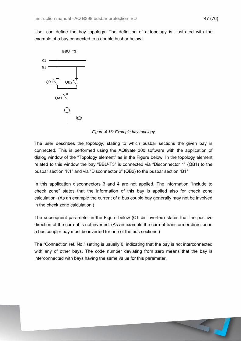
User can define the bay topology. The definition of a topology is illustrated with the
example of a bay connected to a double busbar below:
QB2
QA1
QB1
K1
B1
BBU_T3
Figure 4-16: Example bay topology
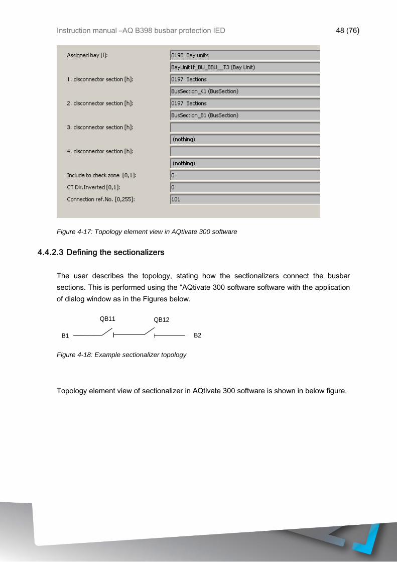
The user describes the topology, stating to which busbar sections the given bay is
connected. This is performed using the AQtivate 300 software with the application of
dialog window of the “Topology element” as in the Figure below. In the topology element
related to this window the bay “BBU-T3” is connected via “Disconnector 1” (QB1) to the
busbar section “K1” and via “Disconnector 2” (QB2) to the busbar section “B1”
In this application disconnectors 3 and 4 are not applied. The information “Include to
check zone” states that the information of this bay is applied also for check zone
calculation. (As an example the current of a bus couple bay generally may not be involved
in the check zone calculation.)
The subsequent parameter in the Figure below (CT dir inverted) states that the positive
direction of the current is not inverted. (As an example the current transformer direction in
a bus coupler bay must be inverted for one of the bus sections.)
The “Connection ref. No.” setting is usually 0, indicating that the bay is not interconnected
with any of other bays. The code number deviating from zero means that the bay is
interconnected with bays having the same value for this parameter.
Instruction manual –AQ B398 busbar protection IED 48 (76)
Figure 4-17: Topology element view in AQtivate 300 software
4.4.2.3 Defining the sectionalizers
The user describes the topology, stating how the sectionalizers connect the busbar
sections. This is performed using the “AQtivate 300 software software with the application
of dialog window as in the Figures below.
QB12
B1 B2
QB11
Figure 4-18: Example sectionalizer topology
Topology element view of sectionalizer in AQtivate 300 software is shown in below figure.

Instruction manual –AQ B398 busbar protection IED 49 (76)
In this example the sectionalizer interconnects the bus sections B1 and B2. The closed
status is the result of closed states QB11 AND QB12. This is the task of the user to
compose a graphic equation for the binary variable “SecStat_SectClosed_GrI_B()”.
Similarly the disconnector status error is composed in AQtivate 300 software for the binary
variable “SecStat_StatErr_GrI_B(Status Error””).
4.4.3 APPLICATION EXAMPLES
These application examples show typical solutions for defining the busbar topology.
Based on these examples, also the details of here not discussed busbar configurations
can be defined. The individual examples show the graphic connections of the bay units
and the parameter setting of the topology objects.

Instruction manual –AQ B398 busbar protection IED 50 (76)
4.4.3.1 Example 1: Bay connected to a single busbar
QB1
QA1
Figure 4-19 Example bay topology of singe busbar
In this simple bay configuration the status signals indicating the closed and open state of
the disconnector are connected to “DC1Close” and “DC1Open inputs”. All other “DCOpen”
inputs are connected to logic “True”.
In the second indicated solution the connection of the bay is fixed to “DC1Close” of the
function block. All other “DCOpen” inputs are connected to logic “True”.
Figure below shows Function block connection examples for single busbar system.

Instruction manual –AQ B398 busbar protection IED 51 (76)
The parameters describing the topology are shown in Figure below.
Figure 4-20: Topology element view in AQtivate 300 software of single busbar setting
4.4.3.2 Example 2: Bay connected to a double busbar
Example bay topology of double busbar system can be seen in the picture below.
Figure 4-21QB2
Q
A
1
Q
B
1
K
1 B
1
B
B
U
_
T
3
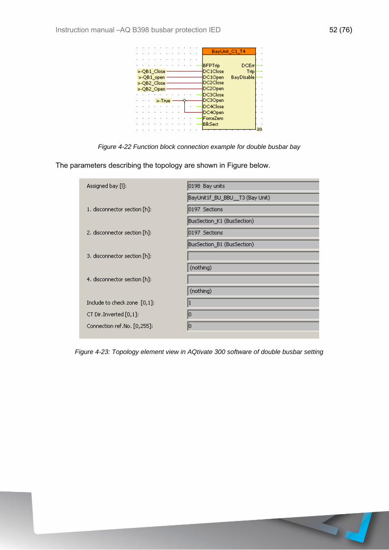
Instruction manual –AQ B398 busbar protection IED 52 (76)
Figure 4-22 Function block connection example for double busbar bay
The parameters describing the topology are shown in Figure below.
Figure 4-23: Topology element view in AQtivate 300 software of double busbar setting

Instruction manual –AQ B398 busbar protection IED 53 (76)
4.4.3.3 Example 3: Bus coupler bay with one current transformer
Example bay topology of bus coupler is shown in figure below.
Figure 4-24 Function block connection example of bus coupler
There are two topology elements assigned to this bus coupler bay: one for the side of
QB1 and one for the side of QB2, the current positive direction for the second one must
be inverted.
Both topology elements refer to the same bay unit.
In this application also the state of the circuit breaker is to considered: in its open state the
measured current must be disclosed to correctly clear the dean zone faults between the
circuit breaker and the current transformer.
Q
B
1
Q
B
2
Q
A
1
K
1 B
1

Instruction manual –AQ B398 busbar protection IED 54 (76)
The algorithm automatically disclosed the current measured by this current transformer if
the connected busbar sections are interconnected also by any other element of the
busbar system. This bypass is identified if two topology elements refer to the same bay
unit.
The topology element related to QB1 is as follows:
Figure 4-25: Topology element view in AQtivate 300 software of bus coupler setting
The topology element related to QB2 is as follows:

Instruction manual –AQ B398 busbar protection IED 55 (76)
Figure 4-26: Topology element view in AQtivate 300 software of bus coupler setting
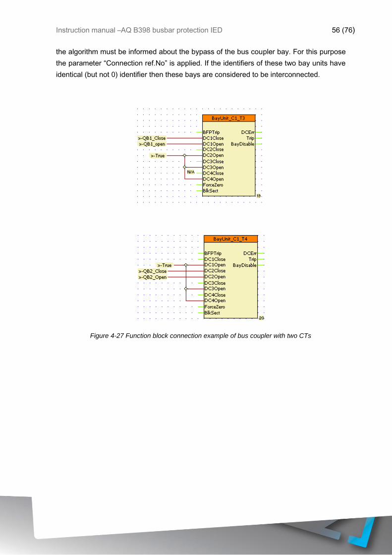
4.4.3.4 Example 4: Bus coupler bay with two current transformers
Example bay topology of bus coupler with two current transformers is shown in figure
below.
To describe this configuration two “Bay unit” function blocks are applied. The current
transformers must be connected in overlapping arrangement. Because of overlapping, the
“Open” state of the circuit breaker need not disclose the current.
When however the bus sections are interconnected also by any other element of the
busbar system, then the automatic disclosing the current is also needed. For this purpose
Q
B
1
Q
B
2
Q
A
1
K
1 B
1
Instruction manual –AQ B398 busbar protection IED 56 (76)
the algorithm must be informed about the bypass of the bus coupler bay. For this purpose
the parameter “Connection ref.No” is applied. If the identifiers of these two bay units have
identical (but not 0) identifier then these bays are considered to be interconnected.
Figure 4-27 Function block connection example of bus coupler with two CTs

Instruction manual –AQ B398 busbar protection IED 57 (76)
Figure 4-28 Topology element views of QB1 and QB2 in AQtivate 300 software of bus coupler setting with two CTs

Instruction manual –AQ B398 busbar protection IED 58 (76)
4.4.3.5 Example 5: Double bus connection with bypass
Example bay topology of bus with bypass is shown in the figure below.
This bay can serve as bus coupler and as a feeder bay at the same time.
The connections of the applied bay unit are as follows.
Figure 4-29 Function block connection example of bus with bypass
The related topology element is a s follows.
Q
B
2
Q
A
1
Q
B
1
Q
B
7
K
1 B
1
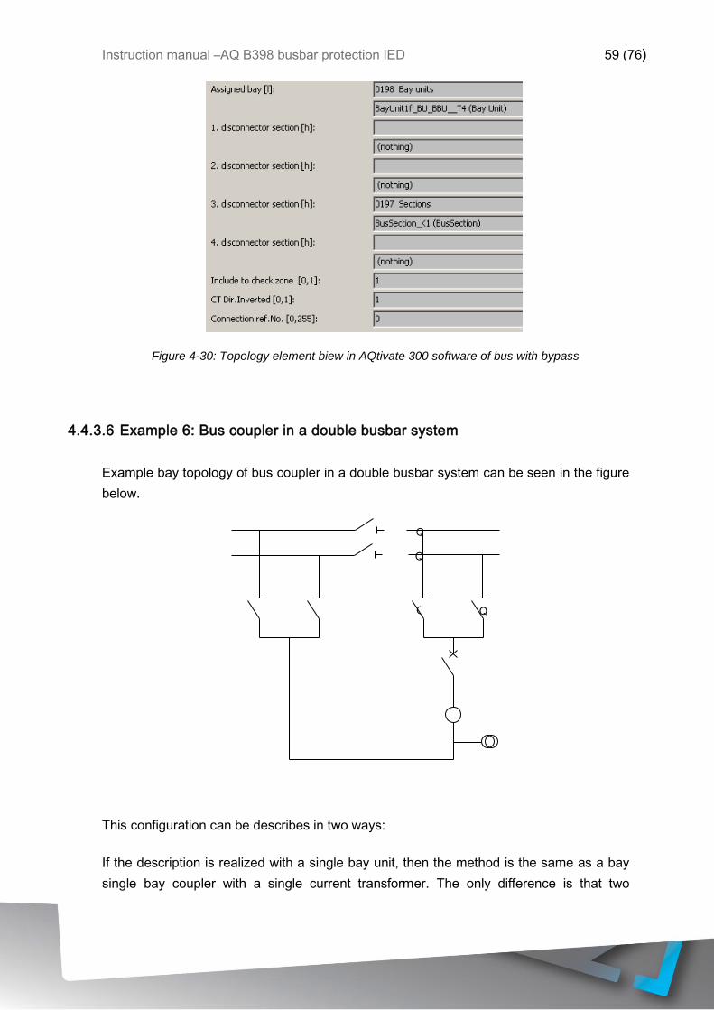
Instruction manual –AQ B398 busbar protection IED 59 (76)
Figure 4-30: Topology element biew in AQtivate 300 software of bus with bypass
4.4.3.6 Example 6: Bus coupler in a double busbar system
Example bay topology of bus coupler in a double busbar system can be seen in the figure
below.
This configuration can be describes in two ways:
If the description is realized with a single bay unit, then the method is the same as a bay
single bay coupler with a single current transformer. The only difference is that two
Q
B
2
Q
B
1
Q
B
2
0 Q
A
1
Q
B
1
0
Q
B
1
1
Q
B
2
1
K
1 B
1
K
2 B
2
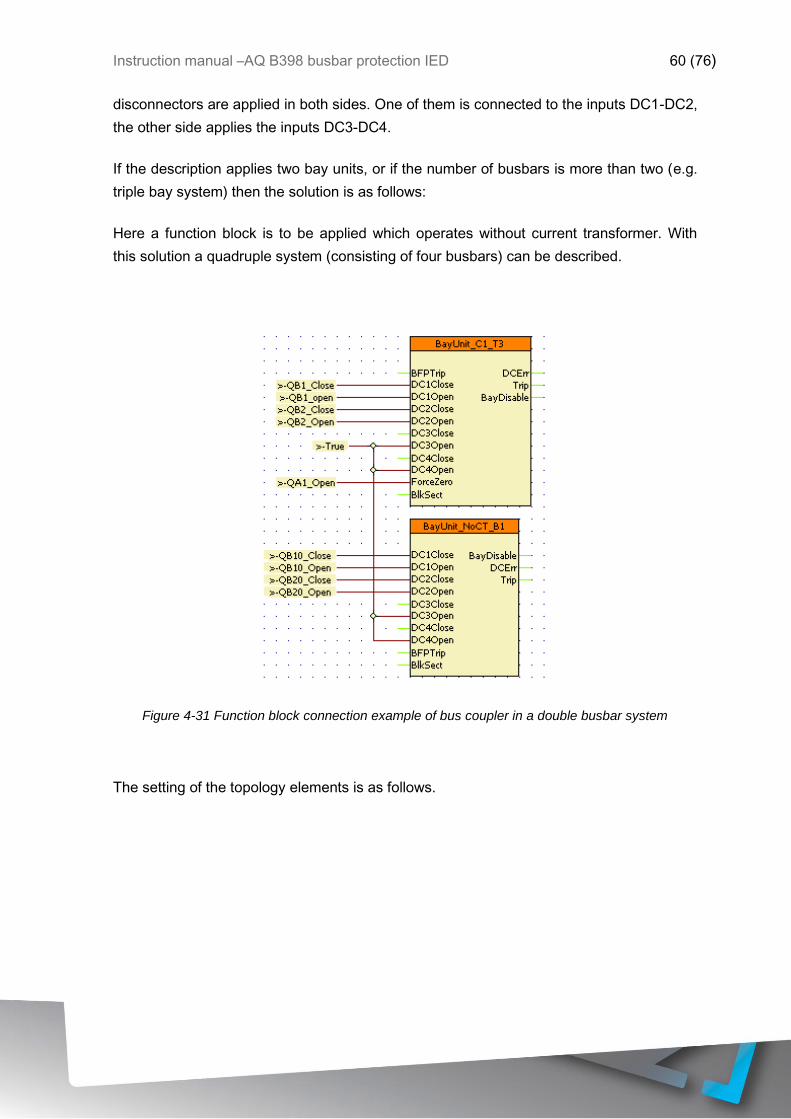
Instruction manual –AQ B398 busbar protection IED 60 (76)
disconnectors are applied in both sides. One of them is connected to the inputs DC1-DC2,
the other side applies the inputs DC3-DC4.
If the description applies two bay units, or if the number of busbars is more than two (e.g.
triple bay system) then the solution is as follows:
Here a function block is to be applied which operates without current transformer. With
this solution a quadruple system (consisting of four busbars) can be described.
Figure 4-31 Function block connection example of bus coupler in a double busbar system
The setting of the topology elements is as follows.
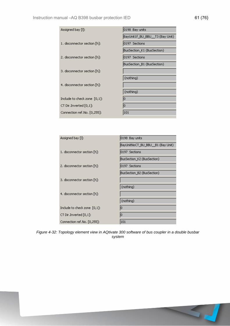
Instruction manual –AQ B398 busbar protection IED 61 (76)
Figure 4-32: Topology element view in AQtivate 300 software of bus coupler in a double busbar system

Instruction manual –AQ B398 busbar protection IED 62 (76)
5 CONSTRUCTIONS AND INSTALLATION
The Arcteq AQ-B398 busbar protection IED consists of hardware modules. Due to
modular structure optional positions for the slots can be user defined in the ordering of the
IED to include I/O modules and other types of additional modules. An example module
arrangement configuration of the AQ-B398 is shown in the figure below. Visit
https://configurator.arcteq.fi/ to see all of the available options.
Figure 5-1 An example module arrangement configuration of the AQ-B398 IED.
Table 5-1 Hardware modules description.
Position Module identifier Explanation
A-B PS+ 1601 Power supply unit, 85-265 VAC, 88-300 VDC
D,E,F CT + 5151 Analog current input module
H,I,J R4+ 01 Signaling output module, 4 output contacts (switchover
type)
U O12+ 1101 Binary input module, 12 inputs, threshold 110 VDC
N R8+ 00 Signaling output module, 8 output contacts
C,G,K,L,M,
O,P,R,S,T
Spare -
V CPU+ 1201 Processor and communication module
5.1 CPU MODULE
The CPU module contains all the protection, control and communication functions of the
AQ 3xx device. Dual 500 MHz high- performance Analog Devices Blackfin processors
separates relay functions (RDSP) from communication and HMI functions (CDSP).
Reliable communication between processors is performed via high- speed synchronous
serial internal bus (SPORT).

Instruction manual –AQ B398 busbar protection IED 63 (76)
Each processor has its own operative memory such as SDRAM and flash memories for
configuration, parameter and firmware storage. CDSP’s operating system (uClinux)
utilizes a robust JFFS flash file system, which enables fail-safe operation and the storage
of, disturbance record files, configuration and parameters.
After power-up the RDSP processor starts -up with the previously saved configuration and
parameters. Generally, the power-up procedure for the RDSP and relay functions takes
approx. 1 sec. That is to say, it is ready to trip within this time. CDSP’s start-up procedure
is longer, because its operating system needs time to build its file system, initializing user
applications such as HMI functions and the IEC61850 software stack.
The built-in 5- port Ethernet switch allows AQ 3xx device to connect to IP/Ethernet- based
networks. The following Ethernet ports are available:
▪ Station bus (100Base-FX Ethernet)
▪ Redundant Station bus (100Base-FX Ethernet)
▪ Process bus (100Base-FX Ethernet)
▪ EOB (Ethernet over Board) user interface
▪ Optional 100Base-Tx port via RJ-45 connector
Other communication
• RS422/RS485/RS232 interfaces
• Plastic or glass fiber interfaces to support legacy protocols
• Process-bus communication controller on COM+ card
5.2 POWER SUPPLY MODULE
The power supply module converts primary AC and/or DC voltage to required system
voltages. Redundant power supply cards extend system availability in case of the outage
of any power source and can be ordered separately if required
Figure 5-2 Connector allocation of the 30W power supply unit

Instruction manual –AQ B398 busbar protection IED 64 (76)
Main features of the power supply module
• 30W input
• Maximum 100ms power interruption time: measured at nominal input voltage with nominal
power consumption
• IED system fault contacts (NC and NO): device fault contact and also assignable to user
functions. All the three relay contact points (NO, NC, COM) are accessible to users 80V-
300VDC input range, AC power is also supported
• Redundant applications which require two independent power supply modules can be
ordered optionally
• On-board self-supervisory circuits: temperature and voltage monitors
• Short-circuit-protected outputs
• Efficiency: >70%
• Passive heat sink cooling
• Early power failure indication signals to the CPU the possibility of power outage, thus the
CPU has enough time to save the necessary data to non-volatile memory
No. Name
1 AuxPS+
2 AuxPS-
3 Fault Relay Common
4 Fault Relay NO
5 Fault Relay NC
"A" "B" PS+/1030

Instruction manual –AQ B398 busbar protection IED 65 (76)
5.3 BINARY INPUT MODULE
The inputs are galvanic isolated and the module converts high-voltage signals to the
voltage level and format of the internal circuits. This module is also used as an external
IRIG-B synchronization input. Dedicated synchronization input (input channel 1) is used
for this purpose.
The binary input modules are
• Rated input voltage: 110/220Vdc
• Clamp voltage: falling 0.75Un, rising 0.78Un
• Digitally filtered per channel
• Current drain approx.: 2 mA per channel
• 12 inputs.
• IRIG-B timing and synchronization input
No. Name
1 BIn_F01
2 BIn_F02
3 BIn_F03
4 Opto-(1-3)
5 BIn_F04
6 BIn_F05
7 BIn_F06
8 Opto-(4-6)
9 BIn_F07
10 BIn_F08
11 BIn_F09
12 Opto-(7-9)
13 BIn_F10
14 BIn_F11
15 BIn_F12
16 Opto-(10-12)
"F" O12+/1101

Instruction manual –AQ B398 busbar protection IED 66 (76)
5.4 BINARY OUTPUT MODULES FOR SIGNALING
The signaling output modules can be ordered as 8 relay outputs with dry contacts.
• Rated voltage: 250 V AC/DC
• Continuous carry: 8 A
• Breaking capacity, (L/R=40ms) at 220 V DC: 0,2 A
• 8 contacts, 7 NO and 1 NC
No. Name
1 BOut_H01 Common
2 BOut_H01 NO
3 BOut_H02 Common
4 BOut_H02 NO
5 BOut_H03 Common
6 BOut_H03 NO
7 BOut_H04 Common
8 BOut_H04 NO
9 BOut_H05 Common
10 BOut_H05 NO
11 BOut_H06 Common
12 BOut_H06 NC
13 BOut_H07 Common
14 BOut_H07 NO
15 BOut_H08 Common
16 BOut_H08 NC
"H" R8+/80

Instruction manual –AQ B398 busbar protection IED 67 (76)
5.5 TRIPPING MODULE
The tripping module applies direct control of a circuit breaker. The module provides fast
operation and is rated for heavy duty controlling.
The main characteristics of the trip module:
• 4 independent tripping circuits
• High-speed operation
• Rated voltage: 110V, 220V DC
• Continuous carry: 8 A
• Making capacity: 0.5s, 30 A
• Breaking capacity: (L/R=40ms) at 220 VDC: 4A
• Trip circuit supervision for each trip contact
No. Name
1 Trip1 +
2 Trip1 -
3 Trip1 NO
4 Trip 2 +
5 Trip 2 -
6 Trip 2 NO
7 Trip 3 +
8 Trip 3 -
9 Trip 3 NO
10 Trip 4 +
11 Trip 4 -
12 Trip 4 NO
"E" TRIP+/2101

Instruction manual –AQ B398 busbar protection IED 68 (76)
5.6 VOLTAGE MEASUREMENT MODULE
For voltage related functions (over- /under -voltage, directional functions, distance function,
power functions) or disturbance recorder functionality this module is needed. This module
also has capability for frequency measurement.
For capacitive voltage measurement of the synchrocheck reference, the voltage
measurement module can be ordered with reduced burden in channel VT4. In this module
the burden is < 50 mVA.
The main characteristics of the voltage measurement module:
• Number of channels: 4
• Rated frequency: 50Hz, 60Hz
• Selectable rated voltage (Un): 100/√3, 100V, 200/√3, 200V by parameter
• Voltage measuring range: 0.05 Un – 1.2 Un
• Continuous voltage withstand: 250 V
• Power consumption of voltage input: ≤1 VA at 200V (with special CVT module the burden
is < 50 mVA for VT4 channel)
• Relative accuracy: ±0,5 %
• Frequency measurement range: ±0,01 % at Ux 25 % of rated voltage
• Measurement of phase angle: 0.5º Ux 25 % of rated voltage
No. Name
1 U L1->
2 U L1<-
3 U L2->
4 U L2<-
5 U L3->
6 U L3<-
7 U Bus->
8 U Bus<-
"D" VT+/2211
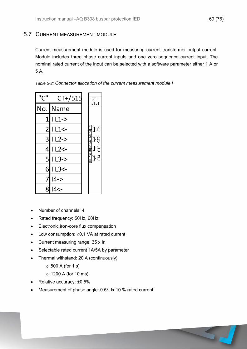
Instruction manual –AQ B398 busbar protection IED 69 (76)
5.7 CURRENT MEASUREMENT MODULE
Current measurement module is used for measuring current transformer output current.
Module includes three phase current inputs and one zero sequence current input. The
nominal rated current of the input can be selected with a software parameter either 1 A or
5 A.
Table 5-2: Connector allocation of the current measurement module I
• Number of channels: 4
• Rated frequency: 50Hz, 60Hz
• Electronic iron-core flux compensation
• Low consumption: ≤0,1 VA at rated current
• Current measuring range: 35 x In
• Selectable rated current 1A/5A by parameter
• Thermal withstand: 20 A (continuously)
o 500 A (for 1 s)
o 1200 A (for 10 ms)
• Relative accuracy: ±0,5%
• Measurement of phase angle: 0.5º, Ix 10 % rated current
No. Name
1 I L1->
2 I L1<-
3 I L2->
4 I L2<-
5 I L3->
6 I L3<-
7 I4->
8 I4<-
"C" CT+/5151
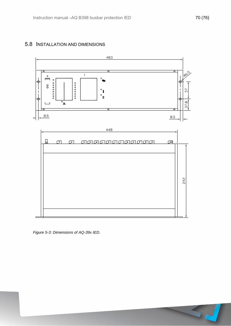
Instruction manual –AQ B398 busbar protection IED 70 (76)
5.8 INSTALLATION AND DIMENSIONS
Figure 5-3: Dimensions of AQ-39x IED.

Instruction manual –AQ B398 busbar protection IED 71 (76)
Figure 5-4: Panel cut-out and spacing of AQ-39x IED.

Instruction manual –AQ B398 busbar protection IED 72 (76)
6 TECHNICAL DATA
6.1 PROTECTION FUNCTIONS
6.1.1 BUSBAR DIFFERENTIAL PROTECTION
Table 6-1: Centralized busbar protection technical data
Operation time
Idiff > 2xIn
Idiff > 5xIn
typically <20ms
typically <15ms
Reset ratio 0.7
Reset time 60ms
Measurement inaccuracy 2%
Table 6-2: Distributed busbar protection technical data
Operation time
Idiff > 2xIn
Idiff > 5xIn
typically 30ms
typically <20ms
Reset ratio 0.7
Reset time 60ms
Measurement inaccuracy 2%
6.2 HARDWARE
6.2.1 POWER SUPPLY MODULE
Rated voltage 80-300Vac/dc
Maximum interruption 100ms
Maximum power consumption
30W
6.2.2 CURRENT MEASUREMENT MODULE
Nominal current 1/5A (parameter settable)
0.2A (ordering option)
Number of channels per module 4
Rated frequency 50Hz
60Hz (ordering option)
Burden <0.1VA at rated current
Thermal withstand 20A (continuous)
500A (for 1s)
1200A (for 10ms)
Current measurement range 0-50xIn

Instruction manual –AQ B398 busbar protection IED 73 (76)
6.2.3 VOLTAGE MEASUREMENT MODULE
Rated voltage Un 100/√3, 100V, 200/√3, 200V (parameter
settable)
Number of channels per module 4
Rated frequency 50Hz
60Hz (ordering option)
Burden <1VA at 200V
Voltage withstand 250V (continuous)
Voltage measurement range 0.05-1.2xUn
6.2.4 BINARY INPUT MODULE
Rated voltage Un 110 or 220Vdc (ordering option)
Number of inputs per module 12 (in groups of 3)
Current drain approx. 2mA per channel
Breaking capacity 0.2A (L/R=40ms, 220Vdc)
6.2.5 BINARY OUTPUT MODULE
Rated voltage Un 250Vac/dc
Number of outputs per module 7 (NO) + 1(NC)
Continuous carry 8A
Breaking capacity 0.2A (L/R=40ms, 220Vdc)
6.2.6 HIGH SPEED TRIP MODULE
Rated voltage Un 110/220Vdc
Number of outputs per module 4
Continuous carry 8A
Making capacity 30A (0.5s)
Breaking capacity 4A (L/R=40ms, 220Vdc)
6.3 TESTS AND ENVIRONMENTAL CONDITIONS
6.3.1 DISTURBANCE TESTS
EMC test CE approved and tested according to EN
50081-2, EN 50082-2
Emission
- Conducted (EN 55011 class A) 0.15 - 30MHz
- Emitted (EN 55011 class A) 30 - 1 000MHz
Immunity
- Static discharge (ESD) (According to
IEC244-22-2 and EN61000-4-2, class III)
Air discharge 8kV
Contact discharge 6kV
- Fast transients (EFT) (According to
EN61000-4-4, class III and IEC801-4, level
4)
Power supply input 4kV, 5/50ns
other inputs and outputs 4kV, 5/50ns

Instruction manual –AQ B398 busbar protection IED 74 (76)
- Surge (According to EN61000-4-5
[09/96], level 4)
Between wires 2 kV / 1.2/50µs
Between wire and earth 4 kV / 1.2/50µs
- RF electromagnetic field test (According.
to EN 61000-4-3, class III)
f = 80….1000 MHz 10V /m
- Conducted RF field (According. to EN
61000-4-6, class III)
f = 150 kHz….80 MHz 10V
6.3.2 VOLTAGE TESTS
Insulation test voltage acc- to IEC
60255-5
2 kV, 50Hz, 1min
Impulse test voltage acc- to IEC 60255-
5
5 kV, 1.2/50us, 0.5J
6.3.3 MECHANICAL TESTS
Vibration test 2 ... 13.2 Hz ±3.5mm
13.2 ... 100Hz, ±1.0g
Shock/Bump test acc. to IEC 60255-
21-2
20g, 1000 bumps/dir.
6.3.4 CASING AND PACKAGE
Protection degree (front) IP 54 (with optional cover)
Weight 6kg net
7kg with package
6.3.5 ENVIRONMENTAL CONDITIONS
Specified ambient service temp. range -10…+55°C
Transport and storage temp. range -40…+70°C

Instruction manual –AQ B398 busbar protection IED 75 (76)
7 ORDERING INFORMATION
Visit https://configurator.arcteq.fi/ to build a hardware configuration, define an ordering
code and get a module layout image.

Instruction manual –AQ B398 busbar protection IED 76 (76)
8 REFERENCE INFORMATION
Manufacturer information:
Arcteq Relays Ltd. Finland
Visiting and postal address:
Wolffintie 36 F 11
65200 Vaasa, Finland
Contacts:
Phone, general and commercial issues (office hours GMT +2): +358 10 3221 370
Fax: +358 10 3221 389
url: www.arcteq.fi
email sales: [email protected]
email technical support: [email protected]