Instruction Manual Accessories List · Instruction Manual Accessories List & Parts List For Your...
66
<& Instruction Manual Accessories List & Parts List For Your Own Safety Read Instruction Manual Before Operating Tool SAKAI SPECIAL CAMERA MFG. CO., LTD.
Transcript of Instruction Manual Accessories List · Instruction Manual Accessories List & Parts List For Your...

<&
Instruction ManualAccessories List
&Parts List
For Your Own Safety Read InstructionManual Before Operating Tool
SAKAI SPECIAL CAMERA MFG. CO., LTD.

SAFETY RULES FOR POWER TOOLS
1. KEEP GUARDS IN PLACE and in working order.
2. REMOVE ADJUSTING KEYS AND WRENCHS. Form the habit of checking to see that keys
and adjusting wrenches arc removed from the tool before turning it on.
3. KEEP WORK AREA CLEAN. Cluttered areas and benches invite accidents.
4. DON'T USE IN DANGEROUS ENVIRONMENT. Don't use power tools in damp or wet locations,
or expose them to rain. Keep work area well lighted.
5. KEEP CHILDREN AWAY. All visitors should be kept safe distance from work area.
6. MAKE WORKSHOP KID PROOF with padlocks, master switches, or by removing starter keys.
7. DON'T FORCE TOOL. It will do the job better and safer at the rate for which it was designed.
8. USE RIGHT TOOL. Don't force tool or attachment to do a job for which it was not designed.
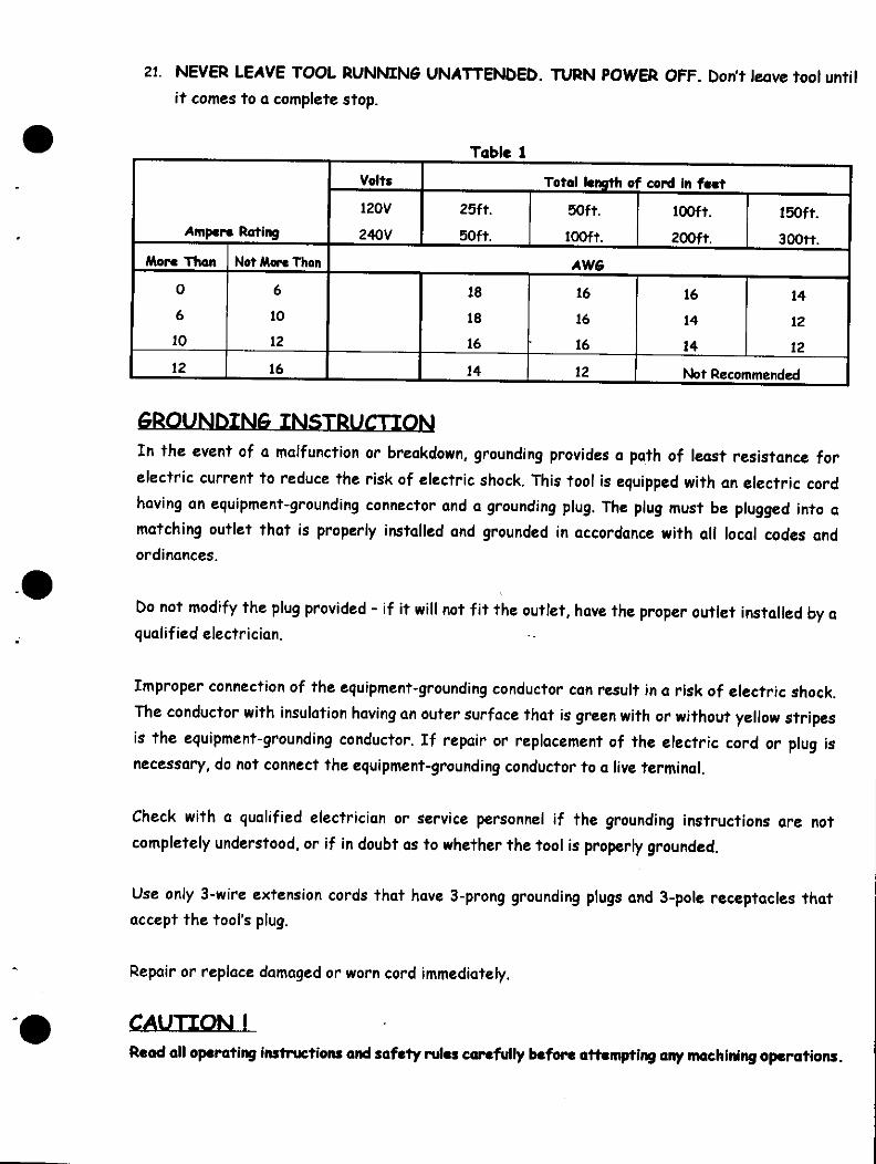
9. USE PROPER EXTENSION CORD. Make sure your extension cord is in good condition. When
using an extension cord, be sure to use one heavy enough to carry the current your product will
draw. An undersized cord will cause a drop in line voltage resulting in loss of power and
overheating. Table 1 shows the correct size to use depending on cord length and nameplate
ampere rating. If in doubt, use the next heavier gage. The smaller the gage number, the
heavier the cord.
10. WEAR PROPER APPAREL. Do not wear loose clothing, gloves, neckties, rings, bracelets or
other jewelry which may get caught in moving parts. Nonslip footwear is recommended. Wear
protective hair covering to contain long hair.
11. ALWAYS USE SAFETY GLASSES. Also use face or dust mask if cuning operation is dusty.
Everyday eyeglasses only have impact resistant lenses, they are NOT safety glasses.
12. SECURE WORK. Use clamps or a vise to hold work when practical. Ifs safer than using your
hand and it frees both hands to operate tool.
13. DON'T OVERREACH. Keep proper footing and balance at all times.
14. MAINTAIN TOOLS WITH CARE. Keep tools sharp and clean for best and safest
performance. Follow instruction for lubricating and changing accessories.
15. DISCONNECT TOOLS before servicing; when changing accessories, such as blades, bits,
cutters, and the like.
16. REDUCE THE RISK OF UNINTENTIONAL STARTING. Make sure switch is in off position
before plugging in.
17. USE RECOMMENDED ACCESSORIES. Consult the owner's manual for recommended
accessories. The use of improper accessories may cause risk of injury to persons.
18. NEVER STAND ON TOOL. Serious injury could occur if the tool is tipped or if the cutting tool
is unintentionally contacted.
19. CHECK DAMAGED PARTS. Before further use of the tool, a guard or other part that is
damaged should be carefully checked to determine that it will operate properly and perform
its intended function - check for alignment of moving parts, binding of moving parts, breakage
of parts, mounting, and any other conditions that may affect its operation. A guard or other
part that is damaged should be properly repaired or replaced.
20. DIRECTION OF FEED. Feed work into a blade or cutter against the direction of rotation of
21. NEVER LEAVE TOOL RUNNING UNATTENDED. TURN POWER OFF. Don't leave tool until
it comes to a complete stop.
Table 1
Ampere Rating
More Than
0
6
10
12
Not More Than
6
10
12
16
Volts
120V
240V
Total length of cord in feet
25ft.
50ft.
50ft.
100ft.
100ft.
200ft.
150ft.
300tt.
AW6
18
18
16
14
16
16
16
12
16
14
14
14
12
12
Not Recommended
6EQUN5IN6 INSTRUCTION
In the event of a malfunction or breakdown, grounding provides a path of least resistance for
electric current to reduce the risk of electric shock. This tool is equipped with an electric cord
having an equipment-grounding connector and a grounding plug. The plug must be plugged into a
matching outlet that is properly installed and grounded in accordance with all local codes and
ordinances.
Do not modify the plug provided - if it will not fit the outlet, have the proper outlet installed by a
qualified electrician.
Improper connection of the equipment-grounding conductor can result in a risk of electric shock.
The conductor with insulation having an outer surface that is green with or without yellow stripes
is the equipment-grounding conductor. If repair or replacement of the electric cord or plug is
necessary, do not connect the equipment-grounding conductor to a live terminal.
Check with a qualified electrician or service personnel if the grounding instructions are not
completely understood, or if in doubt as to whether the tool is properly grounded.
Use only 3-wire extension cords that have 3-prong grounding plugs and 3-polc receptacles that
accept the tool's plug.
Repair or replace damaged or worn cord immediately.
CAUTION \d all operating instructions and safety rules carefully before attempting any machining operations.

INSTRUCTION MANUAL
ContentsMini-lathe ML-360
Illustration A Specifications 1
Milling Attachment MA-360
Illustration 4 Specifications 2
[1] « Mechanism and Operation» 3
1. Starting A Stopping the Main Spindle 3
2. Main Spindle Speed 3
(1) Adjusting the Speed 3
(2) Selecting the proper Main
Spindle Speed 4
(3) Workpiece and Main Spindle rpm 4
3. Carriage 4
4. Tailstock 5
5. Handwheel Calibration 5
[2] « Holding the Workpiece» 6
1. Holding with a Chuck 6
(1) 3-Jaw Universal Chuck (No.3501) 6
A. Fitting the Jaws 6
a) Normal Jaw Fitting 6
b) Reversed Jaw Fitting 7
(2) 4-Jaw Independent Chuck (No.3502) 7
A. Jaw Reversing 7
B. Centering the Workpiece 7
a) Centering 7
(3) Fitting and Removing the Chuck 8
A. Fitting the Chuck 8
B. Removing the Chuck 8
(4) Collet Chuck (No.3509) 8
A. Fitting the Collet Chuck 9
a) Fitting the Collet Chuck 9
B. Holding the Workpiece 10
2. Holding with Centers 10
(1) Tail Spindle Dead Center (No.3505) 10
(2) Main Spindle Dead Center (No.3505) 10
(3) Live Center (No. 3507) 10
(4) Fitting the Centers 11
A. Fitting a Tail Spindle Center 11
B. Fitting Two Centers 11
a) Fitting the Centers 11
b) Removing the Centers 12
[3] « Cutting Tools » 13
1. Types of Cutting Tools 13
(1) Fitting the Cutting Tools to the
Tool post 14
[4] « Machining» 15
1. Cylindrical Turning 15
2. Facing Cuts 16
3. Step Turning 16
4. Cut Off 17
(1) The Cut Off Procedure 17
5. Centering 17
(1) Center 17
A. The Centering Procedure 18
6. Boring 18
(1) The Boring Procedure 18
[5] «Machining with Accessories» 19
1. Compound Slide (No.35317) 19
(1) Fitting the Compound Slide 19
2. Steady Rest (No.3520) 19
(1) Fitting the Steady Rest 20

3. Traveling Rest (No. 3521) 21
(1) Fitting the Traveling Rest 21
4. T-slot face plate (No.3523) 22
(1) Fitting the Face Plate 22
5. Automatic Feed/Thread Cutting
Attachment (No.35311) 23
(1) Fitting the Feed/Thread Attachment 24
(2) Operating the Feed/Thread
Attachment 25
(3) Threading 25
6. Slow Speed Attachment (No.3519) 26
(1) Fitting the Slow Speed Attachment 26
7. Quick-Change Tool Holder ( No.3581) 27
8. Milling Attachment MA-360 27
(1) Fitting the Milling Attachment 27
(2) Starting and Stopping the
Main Spindle 28
(3) Selecting the Main Spindle Speed 28
(4) Operating each Component 29
(5) Cutting Tools 30
(6) Fitting the Cutting Tools 30
A. Milling Collet 30
B. Drill Chuck 31
C. Cutter Arbor 31
(7) Holding the Workpiece 31
A. With a Chuck 31
B. With a Milling Vise 32
a) Fitting the Vise 32
C. Clamps 32
(8) Machining 33
9. Fine Feed Attachment (No.35331) 34
(1) Fitting the Fine Feed Attachment 34
10. Index Head (No.3535) 35
(1) Fining the Index Head 35
(2) Operating the Index Head 36
A. Changing dividing Plates 36
11. Circular Dividing Table (No.3565) 36
(1) Fitting the Dividing Table 38
(2) Operating the Dividing Table 38
[6] « Safety and Maintenance» 41
[7] «Electric Wiring» 42
[8] «Systcm» 43
[9] « Accessories» 44
[10] «PartsList» 51
The Mini Lathe -360 is a top-quality machine developed with highly sophisticated machining
techniques based on our experience as a leading manufacturer of professional large format
cameras.While compact in size, the ML-360 maintains excellent rigidity and durability, as well as
outstanding performance and accuracy. With a large range of accessories to choose from, the
ML-360 is ideal for a variety of machining operations.

MINI-LATHE ML-360 ILLUSTRATION A SPECIFICATIONS
Heodstock 3 - Jaw Universal Chuck TailstockSpindle Dead Center
ON switchPulley Guard
Switch for Counter-Clockwise
and Clockwise rotation
OFF switch
Tar (stockTailstock Spindle Feed HandwheeJ
Spindle
Tailstock Locking Bolt
Pulley Guard Locking Bolt
Carriage Feed Handwheel
Clutch Knob
Tool Post Carriage
\s Feed Handwheel
(NOTED
Bed
(NOTE 2)
Swing over bed
distance between centers
Swing over Carriage
Center height
Main Spindle through hole
Main Spindle speed
Main spindle taper
Tailstock Spindle travel
Tailstock spindle diameter
Tailstock spindle taper
Carriage cross travel
Carriage longitudinal
travel
Reversible condenser
motor, single phase
Dimensions
Weight
6" *
14.173"
3.779" *
3"
5/8"*
260, 520, 845. 970, 1845, 286060Hz
rpm
Slow speed attachment - 80 / 170 rpm
MT#2
1.771"
0.944"*
MT#2 (short type 40L)
3.346"
Whole range between centers
Input 470W Output 300W
3180 rpm (60Hz)
29.763"L x 14.842'W X 9.645"H
66LBS (30kg) without accessories
16.023"
\" _A
£*./03
— - 14.173" -
<n *
nW'- H88?"
NOTE 1: When moving the
ML-360, never carry it by the
pulley guard. Remove the
pulley guard first, then lift
the machine while supporting
it beneath the bed.
NOTE 2: Only operate the
ML-360 on a flat surface.
(Use 2 M8-clamping bolts at
14.331" pitch to bolt it down).
-1-

ATTACHMENT MA-36O
ILLUSTRATION A SPECIFICATIONS
Reference ScaleLateralRotation
Main Spindle HeadLocking. Bolt
Head Carriage
Locking Bolt
Milling Head Carriage
Vertical Column Motor
Pulley Guard
Locking Bolt
Pulley Guard
Switch
Main Spindle Head
Column MountingMounting Bolts Bracket
Distance between main
spindle and column
Distance between main
spindle nose and tool
post
Main spindle taper
Main spindle quill travel
Chucking capacity
Main spindle nose thread
Main spindle head swing
Main spindle speed
Condenser motor, single
phase
Dimensions
Weight
3.996"
6.654"
8°
1.181"
0.393"*
M24xl.
360°
60Hz
5
240
490
740
1120
2210
rpm
Input 240W (0.32HP)
Output 120W(0.16HP)
3000 rpm (60Hz)
10.236"L x 9-.055"W x
15.748"H
29LBS(13kg)
Reference Scale - Main
Spindle Feed
Main spindle Feed Lever
Main Spindle Feed Shaft*•
Main Spindle QuillLocking Bolt
Collet Chuck
24.921'
-2-
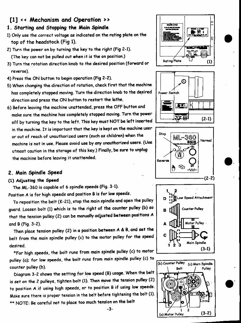
[1] « Mechanism and Operation »1. Starting and Stopping the Main Spindle1) Only use the correct voltage as indicated on the rating plate on the
top of the headstock (Fig 1).
2) Turn the power on by turning the key to the right (Fig 2-1).
(The key can not be pulled out when it is the on position.)
3) Turn the rotation direction knob to the desired position (forward or
reverse).
4) Press the ON button to begin operation (Fig 2-2).
5) When changing the direction of rotation, check first that the machine
has completely stopped moving. Turn the direction knob to the desired
direction and press the ON button to restart the lathe.
6) Before leaving the machine unattended, press the OFF button and
make sure the machine has completely stopped moving. Turn the power
off by turning the key to the left. This key must NOT be left inserted
in the machine. It is important that the key is kept on the machine user
or out of reach of unauthorized users (such as children) when the
machine is not in use. Please avoid use by any unauthorized users. (Use
utmost caution in the storage of this key.) Finally, be sure to unplug
the machine before leaving it unattended.
2. Main Spindle Speed
(1) Adjusting the SpeedThe ML-360 is capable of 6 spindle speeds (Fig. 3-1).
Position A is for high speeds and position B is for low speeds.
To reposition the belt (K-21), stop the main spindle and open the pulley
guard. Loosen bolt (1) which is to the right of the counter pulley (b) so
that the tension pulley (2) can be manually adjusted between positions A
and B (Fig. 3-2).
Then place tension pulley (2) in a position between A A B, and set the
belt from the main spindle pulley (c) to the motor pulley for the speed
desired.
*For high speeds, the bolt runs from main spindle pulley (c) to motor
pulley (a); for low speeds, the bolt runs from main spindle pulley (c) to
counter pulley (b).
Diagram 3-2 shows the setting for low speed (B) usage. When the belt
is set on the 2 pulleys, tighten bolt (1). Then move the tension pulley (2)
to position A if using high speeds, or to position B if using low speeds.
Wake sure there is proper tension in the belt before tightening the bolt (1).
** NOTE: Be careful not to place too much tension on the belt
-3-
Stop
Reverse
1L-3®
OFF
Normal
•(2-2)
.X» , ,JlD !! I! Low Speed Attachment
B Counter Pulley
.* o
(3-1)
(b) Counter Pulley (c) Mflin spindle
Belt I Pulley
/ 1 2(a) Motor Pulley (3-2)

(2) Selecting the Proper Main Spindle Speed
The main spindle speed is determined by the workpiece material and diameter. Nonferrous metals,
such as aluminum or brass, are machined at higher speeds than ferrous metals, such as steel or cast
iron. Smaller diameters require higher speeds. If the motor should stall, or the belt come loose
during operation, turn the machine off immediately. Move the tool away from the workpiece before
resuming machining with a more shallow cut.
(3) Workpiece and Main Spindle rpmMain Spindle rpm is determined by the cutting speed of the tool point. This is calculated by how
many inches per minute the tool cuts into the workpiece.Main spindle rpm N = 36 V / n D
it: pi = 3.14 V : cutting speed (in/min.)
D : diameter of workpiece (in) N • Main spindle rpm
For Example: For an aluminum alloy material with a diameter of
3/4in (cutting speed 55yd/min.), the main spindle
rpm is calculated as follows:
N = 36x55 = 1980 /2.3553.14 x 3/4
Reference Figures are given in Table 4-2.
840 (rpm)
Spindle Speeds
Number of revolution per minute .
C-l
C-2
C-3
0-1
D-2
A
970
1845
2860
B
260
520
845
80
170
(4-1)
Main spindle rpm to the diameter of workpiece
Material
Aluminum alloy
Brass, Copper
Free cutting steel
Cutting speed
Yd/min (V)
55
55
22
Workpiece diameter (D), in
3/16
2860 rpm
2860 rpm
970 rpm
3/8
1845 rpm
1845 rpm
520 rpm
3/4
845 rpm
845 rpm
260 rpm
1 - 3/16
520 rpm
520 rpm
260 rpm
(4-2)
3. Carriage
Handwheel (g) feeds the carriage longitudinally. Handwheel (a)
feeds the cross slide across the bed. Screw (c) is used to adjust
the tightness of the cross slide gib strip. Bolt (d) locks the cross
slide, and bolt (e) locks the carriage to the lathe bed (Fig 5, 6).
-4-(5 )

4. Tailstock
To slide the tails to ck along the lathe bed ways longitudinally,
loosen bolt (h). peed the tailstock spindle with handwheel (i), and
lock the tailstock spindle by tightening bolt (k).
A dead center, live center, or drill chuck can be fitted to the
tailstock spindle. Before fitting these accessories, it is essential
that the tapered arbor of the accessory and the internal taper
in the tailstock spindle are absolutely clean and free of grease. (6)
Feed the tailstock spindle forward by rotating the tailstock
spindle feed handwheel (i). Firmly push in the accessory. The
accessory is automatically ejected when the spindle is retracted
to its fullest extent.
The spindle and handwheel calibration (j) is a useful reference
for drilling and similar operations in the lathe (Fig 6).
5. Handwheel Calibration
Each handwheels has a calibrated cone (I) which can be re-set
zero as a reference.
After taking a roughing cut, determine the remaining depth of
cut required to finish the workpiece. Set the calibrated cone (I)
to the zero position while holding the handwheel (a) so it does
not move (Fig 7). This makes it easy to keep track of how much
has been removed from the workpiece and how much more needs
to be cut. (7)
One revolution of the handwheel is equivalent to .050 in. feed.
The short graduations are each .001 in. and the long graduations
each represent .005 in.
-5-

[2] « Holding the Workpiccc »
There are several ways of holding the workpiece, depending upon
its shape and size. As a general rule, the workpiece is held with a
chuck. Longer pieces can be held between main spindle and
tailstock spindle centers. Irregular shapes can be secured to the
face plate. For extreme accuracy or repetitive cutting of small
parts, the collet chuck is recommended.
1. Holding With a Chuck
The following types of chucks are available for your ML-360.
- 3-jaw Universal Chuck
-4-jaw Independent Chuck
-Collet Chuck
(1) 3-jaw Universal Chuck (No.3501)
The jaws of the 3-jaw universal chuck are opend and closed by
turning the chuck key (Photo 8). The jaws move simultaneously
and center the workpiece automatically as they close. Please
refer to Figures 9 and 10 for the recommended dimensions of
round or hexagonal workpiece to be held in the 3-jaw chuck.
*In the interest of safety, the recommended chuck capacity
should not be exceeded.
A. Fitting the Jaws
a) Normal Jaw Fining
Turning the chuck key clockwise will cause the scroll in the chuck
to rotate counterclockwise. With the jaws removed, turn the
key until the end of the scroll thread appears in jaw slot No.l.
Then turn back slightly and insert jaw 1 so that the jaw comes in
contact with the scroll. Turn the key farther clockwise to
engage jaw 1 with the scroll thread. Next, the end of the scroll
thread will appear in jaw slot No.3. Follow the same procedures
to fit jaws 2 and 3. It is important to insert the jaws in order
from 1 to 3, so as to make the jaws meet evenly at the center.
-6-
[jPT rNormal Jaw
2.362"*1.574"0
0.551'*
]
(9 )
1.377"*
-i
Reversed Jaw
(10)

b) Reversed Jaw Fining
With all jaws removed from the chuck, follow the same
procedure as normal jaw fitting to fit the set of reversed jaws
in order from 1 to 3 (Fig. 11).
(2) 4-Jaw Independent Chuck (No.3502)
The 4-Jaw independent chuck is used to grip round, square,
rectangular, or irregularly shaped workpieces. Recommended
maximum workpiece dimensions are given in Figures 12 and 13. In
the interest of safety, these dimensions should not be exceeded.
Each of the 4 jaws is operated independently. Therefore, the
jaws do not automatically center the workpiece.
Scroll cut c
®
(11)
A. Jaw Reversing
Remove the jaws with the chuck key provided, and refit the
reversed jaws onto the chuck. There is no specific order in
which the reversed jaws must be attached.
B. Centering the Workpiece
To hold the workpiece with the 4-Jaw independent chuck, the 4
jaws must each be brought into position and tightened evenly. A
surface gauge or cutting tool fitted to the tool post is
convenient reference for this procedure.
a) Centering
1) Open the jaws with the chuck key and hold the workpiece in
approximately the correct position. Adjust two opposite jaws
to grip the work lightly.
0.669" *
Normal Jaw
(12)
1.968-0
1.102' *
Reversed Jaw
(13)
-7-

2) Close the other 2 jaws alternately to grip the workpiece as
uniformly as possible.
3) For final centering, set a surface gauge (Photo 14) or cutting
tool tip (Photo 15) close to a reference mark on the face of the
workpiece.
4)Rotate the check and workpiece by hand to check the
reference mark. When the final position is determined, tighten
the jaws evenly.
(3) Fitting and Removing the Chuck
A. Fitting the Chuck
1) Clean the end of the main spindle and back of the chuck
thoroughly.
2) Place the chuck on the end of the main spindle with the
shoulder on the main spindle seated evenly in the undercut on
the back of the chuck.
3) Insert the socket head bolts and tighten them evenly to
secure the chuck (Photo 16).
4) When fitting the 4-jaw independent chuck, tighten the four
bolts evenly in diagonal order.
B. Removing the Chuck
To remove the chuck, reverse the "fitting" procedure. Place a
safety plate of plywood or some soft material on the lathe bed
to protect it in case the chuck is accidentally dropped(Photo 16).
(4) Collet Chuck (No.3509)
A collet is used to grip small diameter workpiece with great
accuracy. The Collet sets (No.35310) includes standard round
collet sizes: 1/8, 3/16,1/4, 5/16,3/8, and 1/2". It also includes a
blank collet which you may finish to any required size (Photo 17).
Surface gauge
ff tt tt f f ff
-8-

A. Fining the Collet Chuck
The collet chuck is fitted to the end of the main spindle and
consists of a collet holder, a collet nut, and interchangeable
collets. A dial gauge, or indicator, is required for centering the
collet chuck.
a) Fitting the Collet Chuck
1) Fit the collet holder to the end of the main spindle by lightly
screwing in the Allen socket head bolts (Photo 19).
2) Use the dial gauge on the outside of the collet holder to
center it. When the collet holder is properly centered, tighten
the socket head bolts firmly (Photo 20).
3) Insert the required collet into the collet holder (Photo 21).
4) Screw in the collet nut just enough to prevent the collet
from rattling around (Photo 22).
Do not tighten the collet chuck without a workpiece in it, as this
will cause the collet to be distorted.
-9-

B. Holding the Workpiece
Insert the workpiece into the collet. Insert one of the 2 locking
bars into the hole in the collet holder, and the other bar in the
hole in the collet nut. Turn the bar in the holder counter
clockwise and the bar in the nut clockwise to tighten.
2. Holding with Centers
When machining a long workpiece, it is best to mount it between
centers in the main spindle and tailstock spindle. The tips of the
center have a 60° conical shape.
(1) Tailstock Spindle Dead Center (No.3505)
The dead center fits into the internal taper of the tailstock
spindle. When the workpiece is rotating, it is important to keep
the tip of the center and the center hole of the workpiece
lubricated constantly to avoid overheating due to friction (Photo
23).
(2) Main Spindle Dead Center (No.3505)
Dead center No. 3505 also fits the internal taper of the main
spindle. When the dead center is used in the main spindle, it dose
not have to be lubricated, because it rotates whit the workpiece.
(3) Live Center (No.3507)
The live center fits into the internal taper of the tailstock
spindle. The tip of the live center rotates with the workpiece on
two ball bearings. This eliminates friction between the
workpiece and the center and makes lubrication unnecessary
(Photo 24).
-10-

(4) Fitting the Centers
It is important to keep the external tapers of the centers and
the internal tapers of the spindles clean and free of grease.
Wipe all contacting surfaces to clear them of chips, dirt, and
lubricants.
A. Fitting a Tail Spindle Center
Single center machining is the process of machining a workpiece
which is held between the chuck on the main spindle and a live or
dead center on the tailstock spindle. The end of the workpiece
that is held by a center must be center drilled.
B. Fitting Two Centers
Machining between two centers is the process of machining when
the workpiece is mounted between one center on the main
spindle and another on the tailstock spindle. For this process,
the workpiece must have been center drilled on both ends.
a) Fitting the Centers
1) Clean the internal taper of the main and tailstock spindles
thoroughly.
2) Fit the dead center into the main spindle. Fit the rotation
stopper bolt (Fig. 25).
3) Fit the dead/live center to the tailstock spindle, ensuring
that both surfaces are clean.
4) Mount the lathe dog (No. 3404) on the workpiece (Fig. 26).
IM)
-11-

5) Place the end of the workpiece (with lathe dog attached)
against the main spindle dead center (Fig. 27).
6) Support the other end of the workpiece with the tailstock
spindle center. Be sure that there is no backlash (Fig. 28).
* The dead center is recommended for more precise cutting.
However, the dead center must be well lubricated so that the
center hole is not damaged.
b) Removing the Centers
Refer to 'Tailstock* on page 5 regarding the automatic ejection
of the accessory from the tailstock spindle. The live center and
the dead center are both removed in the same manner.
To remove the dead center from the main spindle, insert a soft
metal bar (1/2 in. dia. or smaller) into the main spindle from
outer end. Gently tap out the center.
Always hold one hand open under the center when removing it, so
that it does not fall onto the bed (Photo 29).
Rotation stopper bolt
-12-

[3] « Cutting Tools »
1. Types of Cutting Tools
There are 8 types of cutting tools specially designed for your
Mini Lathe. These tools are ready-ground for immediate use.
From time to time, it may become necessary to regrind the tool
to sharpen it, or to reshape it for a certain type of work. Tools
can be ground using a high quality bench grinder fitted with the
correct grinding wheel (Refer to Regrinding Figs. 30~34)
Sakai cutting tools are all made from High Speed Tool Steel.
1) Right-hand finishing tool (No. 3450)
For cylindrical turning and facing cuts. The tool moves from the
right (tailstock) end to the left (headstock) end of the
workpiece for turning (Fig. 30) or across the end of the
workpiece for facing.
2) Roughing tool (No. 3451)
For cylindrical and step turning. The tool moves either from
right to left or vice versa (Fig. 31)
3) External threading tool (No.3452)
For cutting external threads (Fig. 32)
4) Boring Bar -10 mm0 (No.3053)
For boring holes that are 13/32 in. dia. or larger (Fig. 33).
5) Boring Bar - 6 mm0 (No. 3054)
For boring holes that are 1/4 in. dia. or larger (Fig. 33).
When boring with either No. 3053 or No. 3054 boring tool, the
hole must be started with a drill or by some other means. The
boring bars are used to enlarge existing holes.
Workptoe*
D
. Workpiece
-13-

6) Cut Off Tool (No.3055)
This tool is used for cutting off a part of the workpiece or for
cutting grooves in a workpiece. It can also be ground for a
particular application, e.g., cutting an external thread. The tool
is used with the cut off tool holder (No. 3416). Three pieces are
included in each set (Fig. 35).
7) Cut Off Tool Holder (No.3416)
The flat tool holder is used to hold the cut off tool (No.3055)
(Photo 36).
8) Internal threading tool (No.3056)
This tool is used for cutting internal threads (Fig. 37)
9) Unground tool (No.3060)
A square bit which can be ground to suit your specific needs (Fig.
38).
(1) Fitting the Cutting Tools to the Tool Post
The cutting tool must be securely mounted in the tool post. It
must be free of movement or vibration to perform accurate
machining. Note the following points:
1) The overhang of the tool from the tool post surface must not
exceed 1.5 times the thickness of the tool shank. Tools having
excessive overhang may cause an inaccurate cut, or damage
may result to the tool.
2) The point of the cutting tool must be aligned with the center
height or axis of the lathe, A\\gn the tip of the tool with the
tip of the dead center fitted in the main or tailstock spindle
(Fig. 39).
To attain the best tool position, it may be necessary to raise the
tool by inserting a shim under the tool shank. The shim should
have the same dimensions as the tool shank (Fig. 40).
-14-
(M)
. Workpbtt
,1.966" 7] ci
0.314-
(38)
ShimCorrect

3) To secure the tool, tighten the two clamping bolts with the
Allen wrench. The bolts should be tightened alternately and
evenly.
*The tool may shift down slightly when tightening the bolt.
Please take this into consideration when adjusting the shim.
4) Round cutting tools should be fitted to the round tool adaptor
(No.3459) (Photo 41).
Fit the adaptor to the tool post with the round shank of the tool
in the V shape of the adaptor.
[4] « Machining »Generally, machining is the process of rotating the workpiece, applying the tool to it, and adjusting
the feed to remove metal from the workpiece. However, there are many different ways of
machining, depending upon the desired end product.
* Be careful not to touch the chuck, workpiece, or other rotating parts while the lathe is running.
1. Cylindrical Turning
This is the most basic method of machining, and involves cutting the outside of the workpiece.
1) Mount the workpiece in a chuck, on the face plate, or between
lathe centers.
2) Fit the right-hand finishing tool or roughing tool in the tool post.
3) Select the required spindle speed which is determined by the
type of metal and the diameter of the workpiece. Open the
pulley cover, and position the belts according to the speed
required.
4) Advance the cross slide to set the required depth of cut, and
start the main spindle.
* First, make a roughing cut leaving about .008 - .012 in. oversize. Check the dimensions of the
workpiece to determine the remaining cut. Resume machining while occasionally checking the
dimensions until the desired size has been attained.
* Generally, the right-hand finishing tool (No.3450) is used for finishing cuts and the roughing tool
(No.3451) for preliminary cuts.
-15-

* When machining a long workpiece, it is very dangerous to work
with the unmachined end protruding from the headstock main
spindle (Note arrow in Fig. 42). Cut the workpiece to a shorter
length to avoid excessive protrusion.
2. Facing Cuts
This is the process of machining the surface of the workpiece
that is at a right angle to the main spindle.
1) Fit the right-hand finishing tool (No,3450) to the tool post,
aligning it with the center height. Tighten the tool post
after checking the tool angle against the workpiece (Fig. 43).
2) Move the tool into cutting position by adjusting the carriage
longitudinally on the lathe bed.
3) Turn on the motor and commence cutting from the outer edge
to the center of the workpiece by advancing the cross slide.
L- .
t(42)
3. Step Turning
Decide the depth of the step and then follow the procedures for
cylindrical turning (Photo 44).
1) Fit the right-handed finishing tool (No.3450) to the tool post.
2) Feed the carriage so that the cutting tool point comes in
contact with the outer edge of the workpiece. Set the
calibrated cone of each handwheel to zero (for setting
procedure refer to 'Handwheel Calibration', page 5).
* Repeat cylindrical and counterface cutting alternately until
the workpiece is cut to the required dimensions. When a deep
cut is required, it will be necessary to repeat the operation
several times.
-16-
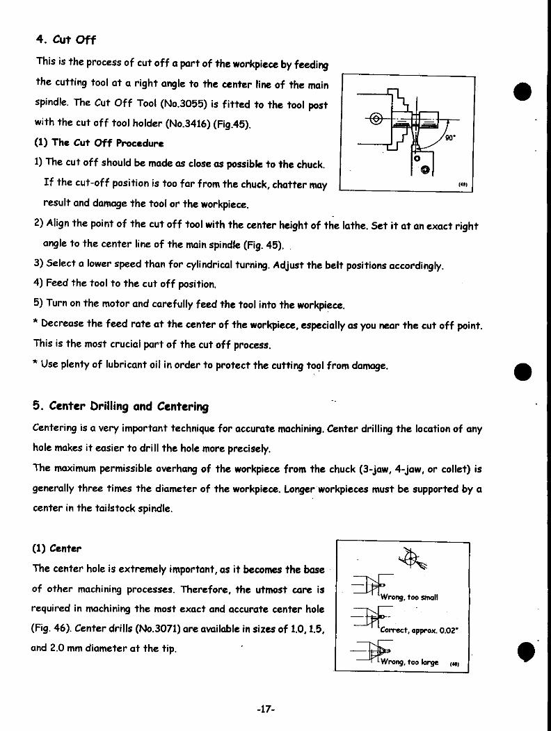
4. Cut Off
This is the process of cut off a part of the workpiece by feeding
the cutting tool at a right angle to the center line of the main
spindle. The Cut Off Tool (No.3055) is fitted to the tool post
with the cut off tool holder (No.3416) (Fig.45).
(1) The Cut Off Procedure
1) The cut off should be made as close as possible to the chuck.
If the cut-off position is too far from the chuck, chatter may
result and damage the tool or the workpiece.
2) Align the point of the cut off tool with the center height of the lathe. Set it at an exact right
angle to the center line of the main spindle (Fig. 45).
3) Select a lower speed than for cylindrical turning. Adjust the belt positions accordingly.
4) Feed the tool to the cut off position.
5) Turn on the motor and carefully feed the tool into the workpiece.
* Decrease the feed rate at the center of the workpiece, especially as you near the cut off point.
This is the most crucial part of the cut off process.
* Use plenty of lubricant oil in order to protect the cutting tool from damage.
5. Center Drilling and Centering
Centering is a very important technique for accurate machining. Center drilling the location of any
hole makes it easier to drill the hole more precisely.
The maximum permissible overhang of the workpiece from the chuck (3-jaw, 4-jaw, or collet) is
generally three times the diameter of the workpiece. Longer workpieces must be supported by a
center in the tailstock spindle.
(1) Center
The center hole is extremely important, as it becomes the base
of other machining processes. Therefore, the utmost care is
required in machining the most exact and accurate center hole
(Fig. 46). Center drills (No.3071) are available in sizes of 1.0,1.5,
and 2.0 mm diameter at the tip.
Wrong, too small
Q--
Corr-ect, approx. 0.02"
Wrong, too large («
-17-
A. The Centering Procedure
1) Mount the workpiece in the 3-jaw, 4-jaw, or collet chuck.
2) Remove the dead center from the tailstock spindle. Insert
the tapered part of the drill chuck (No. 3508) into the tapered
hole of the tailstock spindle.
3) Fit the appropriate center drill in the drill chuck, and tighten
the chuck with the chuck key.
4) Loosen the tailstock locking bolt. Move the tailstock close to
the workpiece and lock it in position.
5) Set the appropriate main spindle speed.
6) Turn the motor on and feed the drill with the tailstock spindle
feed handwhcel.
* The center drill tip is especially susceptible to damage. It must
be fed in slowly using plenty of cutting oil.
6. Boring
Boring is the process of enlarging a hole made by a drill or other
means to a specific size (Photo 47).
* In the case that the workpiece does not already have a hole in
it, one must be made by drilling.
(1) The Boring Procedure
1) Mount the workpiece in the chuck.
2) Fit the boring tool to the tool post using the adaptor (No.
3459). Align the point of the boring tool with the center height
of the lathe.
3) Select the main spindle speed, and adjust the belts.
4) Turn the motor on and feed the tool.
* Due to the length of the boring tool, it may chatter unless the
correct (slow) feed rate is used.
* Be sure to keep the workpiece free of chips and use plenty of
cutting oil for better boring.
-18-

[5] «Machining with Accessories»
A wide range of accessories are available for the ML-360, The
following is an introduction to the use of the accessories.
1. Compound Slide (No.35317)
Any taper is possible with the use of this attachment (Photo 48).
(1) Fitting the Compound Slide
1) Turn the handwheel of the compound slide counter clockwise
to expose the eccentric bush.
2) Insert part (f) of the compound slide (a) into the hole (H) in
the cross slide (Rg 48, Photos 49).
3) Insert the nut (d) into the T-slot on the cross slide, fit the
Allen head bolts (e) through the eccentric bush in the
attachment, and tighten lightly with the Allen wrench (5 mm.).
4) The compound slide body (a) has a scale graduated in 5°
increments to a maximum of 45° on either side. Align the
required angle with the reference mark (L) on the cross slide
and tighten firmly.
5) Fit the tool to be used on the tool post (b).
* For adjusting the height of the tool, refer to 'Fitting Cutting
Toots to the Tool Post*, page 14.
* The tool is fed with the cross feed handwheel (g), and a taper
is cut by turning the feed handwheel (c) on the compound slide
(Photo 50).
* If the top slide (h) is moved too far to the right (Photo 50),
the feed gear may separate from the base (a). To avoid this
danger, stay within the 2.04" maximum feed limit for the
compound slide.
2. Steady Rest (No.3520)
The steady rest is recommended for supporting long, thin
workpieccs in all cutting operations (Photo 51).
-19-

(1) Fining the Steady Rest
1) Hold one end of the workpiece gently with the chuck (Photo
52).
2) Slide the steady rest (a) over the workpiece and place it as
close as possible to the machining area. Attach the steady rest
to the lathe bed with the bolt (e), washer (f), nut (g) and nut
plate (d) (Photo 51, 53).
For turning between centers, position the rest near the center
of the workpiece.
3) Loosen the slide bar clamp bolts (c) and adjust the workpiece.
While slowly turning the chuck by hand, adjust the steady rest
bars (b) so that they hold the workpiece firmly. Clamp the 3
bolts (c) to secure the bars in postition (Photo 54).
* When working with a centered workpiece, it is best to set the
workpiece in the tail spindle before adjusting the 3 bars (b) on
the steady rest.
4) When the workpiece is aligned correctly, clamp the chuck
firmly.
* When tightening the chuck, be sure that there is a very small
space between the steady rest bars and the workpiece, so that
the workpiece can be turned easily by hand. Too much space will
cause inaccurate machining and may damage the tool or
workpiece. Conversely, if the bars are too tight, the workpiece
may be scored, or it may overload the lathe motor.
-20-
5) Lubricate the contact surface between the workpiece and the
steady rest bars well before starting the main spindle (Photo
55).
* If the surface of the workpiece is not perfectly round or
smooth, turn a smooth, round surface first, and then fit the bars
of the steady rest on that surface.
* The maximum diameter to be held with the steady rest is 1.950
in.
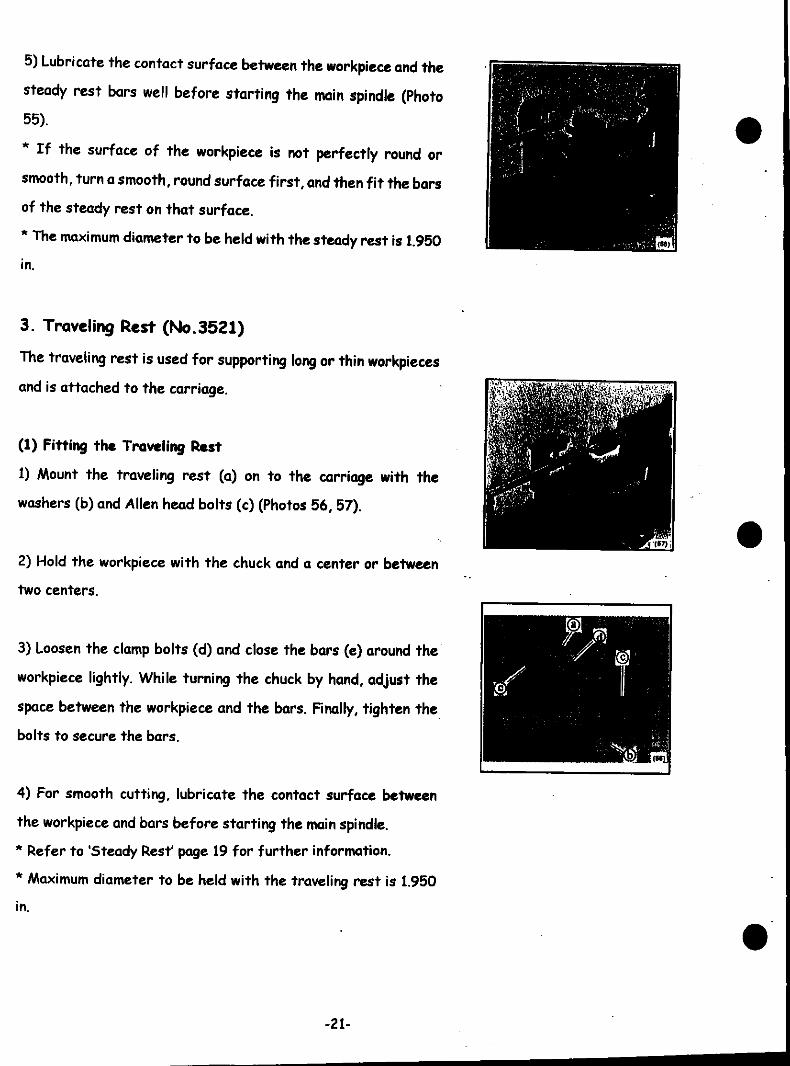
3. Traveling Rest (No.3521)
The traveling rest is used for supporting long or thin workpieces
and is attached to the carriage.
(1) Fitting the Traveling Rest
1) Mount the traveling rest (a) on to the carriage with the
washers (b) and Allen head bolts (c) (Photos 56, 57).
2) Hold the workpiece with the chuck and a center or between
two centers.
3) Loosen the clamp bolts (d) and close the bars (e) around the
workpiece lightly. While turning the chuck by hand, adjust the
space between the workpiece and the bars. Finally, tighten the
bolts to secure the bars.
4) For smooth cutting, lubricate the contact surface between
the workpiece and bars before starting the main spindle.
* Refer to 'Steady Resf page 19 for further information.
* Maximum diameter to be held with the traveling rest is 1.950
in.
-21-
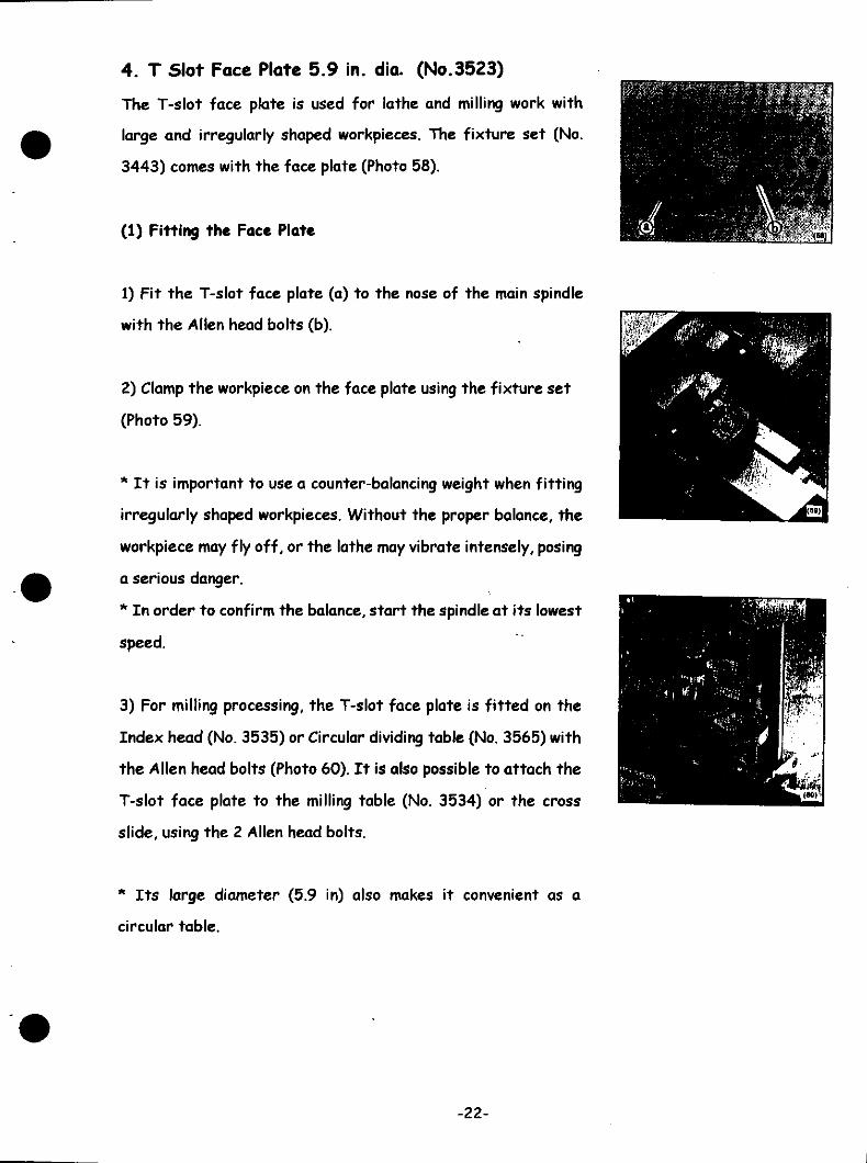
4. T Slot Face Plate 5.9 in. dia. (No.3523)
The T-slot face plate is used for lathe and milling work with
large and irregularly shaped workpieces. The fixture set (No.
3443) comes with the face plate (Photo 58).
(1) Fitting the Face Plate
1) Fit the T-slot face plate (a) to the nose of the main spindle
with the Allen head bolts (b).
2) Clamp the workpiece on the face plate using the fixture set
(Photo 59).
* It is important to use a counter-balancing weight when fitting
irregularly shaped workpieces. Without the proper balance, the
workpiece may fly off, or the lathe may vibrate intensely, posing
a serious danger.
* In order to confirm the balance, start the spindle at its lowest
speed.
3) For milling processing, the T-slot face plate is fitted on the
Index head (No. 3535) or Circular dividing table (No. 3565) with
the Allen head bolts (Photo 60). It is also possible to attach the
T-slot face plate to the milling table (No. 3534) or the cross
slide, using the 2 Allen head bolts.
* Its large diameter (5.9 in) also makes it convenient as a
circular table.
-22-

5. Automatic Feed / Thread Cutting
Attachment (No. 3511)
This accessory allows the longitudinal feed to
be operated automatically. By changing the
gears, it is possible to attain feed rates of
0.0025 or 0.005 in. per revolution of the main
spindle. It is also possible to cut 31 different
unified thread pitches ranging from 10 to 80
threads per inch (Fig. 61, Table 62).
* The automatic feed allows even, accurate,
and precise machining. It also helps to preserve
the tool life.
Automatic f«ed
©Co)©©
0000
Automatic feed(61)
Main Bptndte GMT
H
Right hand
Left hand
Feed perrevolution0.0025 in0.005 in
GearH/ A
20/6040/60
B / C70/2570/25
D/E-/75-/75
Thread cutting
Threads perinch
101112131415161718192022242628303234363840
44R44L485256606468
72R
72L76R
76L80R801
GearA5555
•55555555455555555560455055
.5555555555554545555555555555555555555555
B / C40/2040/3050/2060/4550/3540/2050/3060/3450/3060/4540/2030/2250/3040/2650/35- /4050/4040/3450/4540/3830/4050/60- /2025/4020/2625/3535/4525/4020/3425/45- /2020/38
- /2525/40- /20
D / E30 /-22 / -45 / -26 / -30 /-45 / -40/-45 / -45 / -38 / -60 / -45 / -60 / -60 / -60 / -- /45
60 / -60 / -60 / -60 / -45 / -55 / -55 / -45 / -60 / -60 / -70 / -60 / -60 / -60 / -60 / -60 / -60 / -75 / -75 / -
F / 625 / -35 / -25 / -25 / -25 / -25 / -20 / -20 / -25 / -20 / -20 / -20 / -20 / -20 / -20 / -20 / -20 / -20 / -20 / -20 / -35 /-
50/6020 / -25 /-40/-20 / -20 / -25 /-
25/45
20/38
25/40
For the section marked -, use
of gear.
(62)the collar instead

(1) Fining the Feed/Thread Attachment
The No. 3511 set includes the automatic feed unit and the
thread cutting unit. Each unit is fitted in the same manner.
*(Complete the belt adjustment for main spindle speed before
beginning this fitting procedure.)
1) Switch the clutch control to manual.
2) Open the pulley guard. Using the gear bracket 360 (b), fit the
gear shaft assembly (a) firmly to the lead screw hole located
on the left hand side of the bed (Fig. 63).
3) Loosely attach the bolt (c), key socket (d), washer (e), and nut
(f) to the gear bracket 360 (b). Then mount the bracket on
the gear shaft assembly (a) and lightly clamp it in place with
the Allen head bolt (h) (Fig. 63, 64).
4) Select the feed rate or pitch (refer to Table 62) and prepare
the main spindle gear, and idler gear A~H.
5) Slide the main spindle gear (W) on the end of the spindle until
it touches the step on the left end of the main spindle. Secure
the gear by tightening the setscrew with the Allen key, making
sure that the screw fits into the D-shaped cut (Fig. 65).
6) Attach the lead screw gear D or E to the key socket on the
left side of the gear shaft assembly (a) with the spacer
collar , washer (e), and hexagon nut (i) (Fig. 66).
7) The order of assembly of the idler gear A, B/C, and F/6 is
especially important. Be sure to check Table 62 before
assembling. Loosen the gear shaft bolt (c) and attach the lead
screw gear D or E, adjusting for backlash. Tighten the gear
shaft bolt and fit the gear stopper (j).
8) Engage A with B/C, and B/C with F/6 referring to Figure 67.
9) Rotate the gear bracket 360 (b) using the gear shaft
assembly (a) as the fulcrum, so that the main spindle gear and
idler gear A mesh with proper clearance. Use a strip of paper
between the gears to test the mesh of the gear teeth.
Tighten the Allen head bolt (h) using the Allen key (Fig. 68).
10) Close the pulley guard.
-24-
(93)
(•7)
I <«8|

(2) Operating the Feed/Thread Attachment
Turn on the main spindle and switch the clutch control to automatic. The carriage will move
automatically.
To disengage the automatic feed, switch the clutch control to manual. This releases the clutch,
stopping the carriage movement.
* When the clutch control is in the automatic position, the carriage feed handwheel cannot be
operated by hand. When using the automatic feed, pay attention to the location of the carriage
(tool post) so that it does not hit and damage other parts of the machine.
* With normal rotation of the main spindle, the carriage travels from right to left.
With reverse rotation of the main spindle, the carriage travels from left to right.
Note: The clutch knob on the headstock con only be turned to the automatic feed position while
the main spindle is running.
(3) Thread Cutting
1) Hold the workpiece with the chuck.
2) Set the main spindle speed to the lowest rpm, or to a slow speed with the Slow Speed
Attachment (No. 3519).
3) Fit the external threading tool to the tool post. Start the main spindle and feed the carriage
manually until the tool comes in contact with the outside of the workpiece. At this point, set the
cross feed dial to zero and move the cutting tool
away from the surface.
4) Set the first cutting depth with the cross feed handwheel
and switch the clutch control to automatic.
5) Upon completion of the first threading cut, move the cutting
tool away from the workpiece and stop the main spindle.
* Do not release the clutch until the threading operation
is complete.
6) Reverse the main spindle rotation to return the carriage to
the starting point, and stop the main spindle.
7) Return the cutting tool to the starting point, set the depth of
cut for the second pass, and commence the second pass.
8) Repeat steps 5) to 7) until the thread has been cut to the
required depth (Fig. 69).
Oo not try to cut the thread to full depth all at once. Take several passes, deepening the thread
by .002 to .005 in. on each succeeding pass of the tool.
-25-
l_ / Workpiece
./ r
(HZ-M I
•
External/threading tool
K> Tool post±J.
Depth of cirt
\«i)

6. Slow Speed Attachment (No. 3519)
With this attachment, the main spindle speed can be reduced to
80 rpm or to 170 rpm (Fig.70).
(1) Pitting the Slow Speed Attachment
* When using the automatic feed/thread cutting attachment
and the slow speed attachment at the same time, fit the slow
speed attachment first.
1) Open the pulley guard and remove the V-belt (K-21) from the
main spindle pulley (a).
2) Use the Allen key to remove the Allen head bolt (b) from the
plate below main spindle (Fig. 71).
3) Loosen the setscrew in the pulley retaining ring and remove it
from the main spindle. Then remove the main spindle pulley. Slide
the slow speed gear 100 onto the main spindle and secure it with
the pulley retaining ring (Fig. 71).
4) Mount the attachment with the two Allen head bolts supplied.
Screw the Allen head bolts into bolt hole (c) and bolt hole (b) so
that the gear of the attachment meshes with the slow speed
gear 100 (Fig. 72).
5)Set the belt (K-20) on the attachment pulley and counter
pulley. Next, pass it over the tension pulley, raising the pulley to
create tension in the belt. Tighten the tension bolt.
(70)
Main spindle pulley (a)
Pulley retaining ring
Bolt hole (c)
Allen head bo It (b)(71)
(72)
-26-
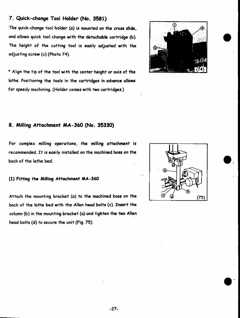
7. Quick-change Tool Holder (No. 3581)
The quick-change tool holder (a) is mounted on the cross slide,
and allows quick tool change with the detachable cartridge (b).
The height of the cutting tool is easily adjusted with the
adjusting screw (c) (Photo 74).
* Align the tip of the tool with the center height or axis of the
lathe. Positioning the tools in the cartridges in advance allows
for speedy machining. (Holder comes with two cartridges.)
8. Milling Attachment MA-360 (No. 35330)
For complex milling operations, the milling attachment is
recommended. It is easily installed on the machined boss on the
back of the lathe bed.
(1) Fitting the Milling Attachment MA-360
Attach the mounting bracket (a) to the machined boss on the
back of the lathe bed with the Allen head bolts (c). Insert the
column (b) in the mounting bracket (a) and tighten the two Allen
head bolts (d) to secure the unit (Fig. 75).
-27-

By following the above procedure, the unit should end up at a
right angle to the surface of the cross slide table. However, for
greater accuracy, use the dial indicator before tightening the
mounting bracket (Fig. 80).
Mount the dial indicator on a rod gripped in a collet in the nose
of the milling attachment. Rotate the spindle of the milling
attachment by hand to take indicator readings from the top of
the table.
(2) Starting/Stopping the Main Spindle
1) The electric current supply must comply with the
specifications indicated on the rating plate on the front of the
pulley guard.
2) To start, push the switch to ON. To stop, push the switch to
OFF (Fig 81).
(3) Selecting the Main Spindle Speed
Loosen the two pulley cover screws (e) and open the pulley guard
(f) to find the speed chart inside (Fig. 82).
There is one pulley cover screw at the front and another at the
back of the unit.
* Belt positions and main spindle speeds are shown in Fig. 83.
* Always turn the machine off before changing the main spindle
speed.
Loosen the hex. bolts (g), to shift the position of the motor
bracket (h). Slide the bracket to the right to decrease belt
tension. Set the belt at the appropriate position, slide the motor
bracket back to the left to apply tension to the belt, and tighten
the hex. bolts (g). Belt tension between the main spindle pulley
(i) and the counter pulley (j) is adjusted with the Allen head
bolts (k) (Fig. 84).
HttfflJtfW
(81)
SPINDLE SPEEDS£ /mln
50 Hi
60 Hi
t210
240
/420
490
a630740
4960
1120
\>1880
2210(•3}
(84)
-28-
Recommended main spindle speeds in relation to cutting tool diameters are indicated in Table 85.
Cutting conditions depend upon the type and material of the cutting tool and the workpiece, etc.
For further information, refer to the lathe turning conditions on Page 4.
Main spindle rpm to tool diameter
Tool diameter
~ 5/32 in
5/32 ~ 3/8
3/8 - 13/16
13/16 - 1-3/16
1-3/16 - 1-9/16
Material
Free cutting steel
1120 rpm
740 rpm
490 rpm
240 rpm
240 rpm
. Aluminum
2210 rpm
1120 rpm .
740 rpm
240 rpm
240 rpm
Plastic
2210 rpm
1120 rpm
740 rpm
240 rpm
240 rpm
(85)
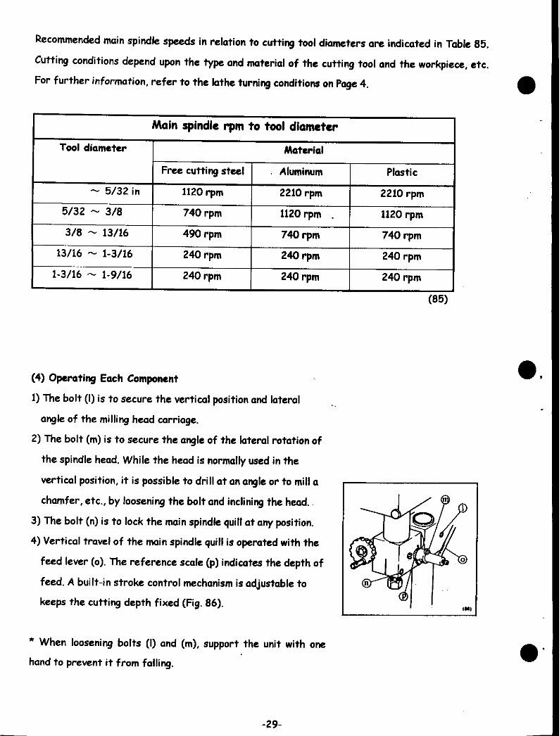
(4) Operating Each Component
1) The bolt (I) is to secure the vertical position and lateral
angle of the milling head carriage.
2) The bolt (m) is to secure the angle of the lateral rotation of
the spindle head. While the head is normally used in the
vertical position, it is possible to drill at an angle or to mill a
chamfer, etc., by loosening the bolt and inclining the head.
3) The bolt (n) is to lock the main spindle quill at any position.
4) Vertical travel of the main spindle quill is operated with the
feed lever (o). The reference scale (p) indicates the depth of
feed. A built-in stroke control mechanism is adjustable to
keeps the cutting depth fixed (Fig. 86).
* When loosening bolts (I) and (m), support the unit with one
hand to prevent it from falling.
-29-
(5) Cutting Tools
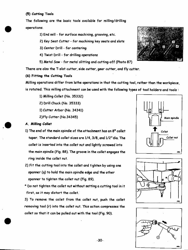
The following are the basic tools available for milling/drilling
operations.
1) End mill - for surface machining, grooving, etc.
2) Key Seat Cutter - for machining key seats and slots
3) Center Drill - for centering
4) Twist Drill - for drilling operations
5) Metal Saw - for metal slitting and cutting-off (Photo 87)
There are also the T-slot cutter, side cutter, gear cutter, and fly cutter.
(6) Fitting the Cutting Tools
Milling operations differ from lathe operations in that the cutting tool, rather than the workpiece,
is rotated. This milling attachment can be used with the following types of tool holders and tools :
1) Milling Collet (No. 35332)
2) Drill Chuck (No. 35333)
1) Cutter Arbor (No. 34341)
2) Fly Cutter (No.34345)
A. Milling Collet
1) The end of the main spindle of the attachment has an 8° collet
taper. The standard collet sizes are 1/4,3/8, and 1/2" dia. The
collet is inserted into the collet nut and lightly screwed into
the main spindle (Fig. 88). The groove in the collet engages the
ring inside the collet nut.
2) Fit the cutting tool into the collet and tighten by using one
spanner (q) to hold the main spindle edge and the other
spanner to tighten the collet nut (Fig. 89).
* Do not tighten the collet nut without setting a cutting tool in it
first, as it may distort the collet.
3) To remove the collet from the collet nut, push the collet
removing tool (r) into the collet nut. This action compresses the
collet so that it can be pulled out with the tool (Fig. 90).
Main spindle
(88)
-30-
(90)

B. Drill Chuck
The drill chuck for milling (No. 35333) has a straight, round
shank of 1/2 in. dia. Insert the drill chuck shank into the 1/2 in.
collet and tighten with the spanner. Fit the drill to the drill
chuck and tighten the chuck with the chuck handle (s)
(Fig. 91)
C. Cutter Arbor
1) The cutter arbor (No. 34341) makes it possible to use a metal
saw or side cutter. It has a 3/8 in. dia. shank and should be
used with the 3/8 in. collet.
2) Attach the cutting tool to the arbor with the collars and nut.
Insert the locking bar into the hole of the cutter arbor, and
tighten the nut with the spanner (Fig. 92).
* When mounting the cutter arbor, make sure that the direction
of the cutter teeth coincides with the direction of rotation of
the main spindle and the cutter arbor.
Main spindle| Collet
Collet nut
II
(7) Holding the Workpiece
A. With a chuck
The workpiece may be held in a 3-jaw, 4-jaw, or collet chuck.
Chucks can be fitted to the chuck mounting adaptor (No. 3503)
(t) on the cross slide for convenience (Fig. 93).
-31-

B. With a Milling Vise
The workpiece can also be held with the milling vise (No. 3542),
which can be fitted directly onto the cross slide (Fig. 94).
a) Fitting the Vise
1) Fit the vise on the cross slide or on the milling table (No.
3534). Loosely clamp the vise with the square nuts and Allen
head bolts, allowing for adjustments.
2) Fit the dial gauge or indicator on the main spindle so that the
measuring point touches the fixed jaw of the vise (Fig. 95).
3) Feed the carriage back and forth and adjust its position until
you attain a zero reading on the dial gauge all the way across.
4) When the vise is in a parallel position, tighten the clamp bolts
firmly.
* After tightening, re-check with the dial gauge to ensure that
the vise has not moved.
C. Clamps
Attach the milling table (No. 3534) to the cross slide. Fit the
Fixtures (No. 3443) using the milling table T-slots, and hold the
workpiece with them (Fig. 96).
(M)
rag)
-32-

(8) Machining
1) Surface Milling
The end mill is generally used in several steps for surface milling.
The fly cutter (No.34345) is useful on broad surfaces or when a
fine finish is required. The cutting diameter can be controlled by
adjusting the cutting tool which is held at a 45° angle in the
body of the fly cutter. To secure the cutting tool, tighten bolt
(u) firmly (Fig. 97).
*Use cutting oil on the workpiece toget a good finish and to
preserve the life of the cutting tool.
2) Slotting
The end mill is also used for slotting. In order to get a more
precise cut, use the fine feed attachment (No, 35331). Refer to
page 35 for details (Fig. 98).
3) Drilling
Use the drill chuck (No. 35333) for drilling operations.
* The reference scale is calibrated in increments of .050 in. To
drill a blind hole, set the scale to the desired depth and lock the
bolt (w). The cut will begin at the point at which the tool is set
and end when it has reached the depth indicated by the reference
scale. The scale will read 0 at the stopping point (Fig. 99).
* When depth adjustment is not required, set the scale to any
position except 0 ~ 1.
4) Metal Slitting
Fig. 1OO illustrates the method of slitting a workpiece. The
spindle speed should be set at the lowest rpm to accommodate
for the large diameter of the cutting tool. Pay close attention to
the cutting depth, direction, and feed rate, as great friction is
generated during this operation. Use cutting fluid on the
workpiece.
-33-
(M)
noat

* Changing the Belt
After a long period of use, the belt will wear from friction and
may snap or tear. To replace the belt, loosen the motor bolts (k)
with the alien key and remove the motor. Next loosen the idler
shaft (x) and pull it out. The counter pulley will come free,
allowing the belt to be removed and replaced. For instructions on
fitting the belt, refer to page 28 and follow the steps in reverse
(Fig. 101).
9. Fine Feed Attachment (No. 35331)
Fitted to the milling attachment, this accessory allows fine
feeding of the main spindle. The handwheel has a scale which is
calibrated in increments of .001 in. One full revolution of the
handwheel equals .050 in. (Photo 102).
(I) Fitting the Fine Feed Attachment
1) 7>ie clutch shaft (c) of the fine feed attachment is fitted
through the main spindle feed shaft hole (H) on the left hand
side of the main spindle head (Fig. 103).
* Pull out the clutch shaft completely before inserting it into the
main spindle feed shaft hole.
2) Secure the fine feed attachment (a) to the main spindle head
with the alien head bolt (d).
* Make sure the handwheel (b) turns easily. If there is any
resistance, loosen the bolt and retighten so that the handwheel
rotates freely,
3) To switch to fine feed, turn the handwheel (b) while pushing in
the clutch shaft (c) until you hear a click and the clutch shaft
snaps in (Fig. 104). The fine feed can now be controlled with
the handwheel (b).
4) To release the fine feed, pull out the clutch shaft (c). The
movement of the main spindle quill can now be controlled with
the lever (o).
-34-
(101)
no?)
(t03)
flM)

10. Index Head (No. 3535)
The index head is used for dividing operations (Photo 105).
The 48-slot dividing plate is supplied with the index head, and
the 30, 36, and 40-slot dividing plates are available as
accessories. The divisions listed in Table 106 can be made using
these plates.
Plates
30
36
40
48
Division
2
2
2
2
3
3
3
4
4
4
5
5
6
6
6
8
8
9
10
10
12
12
15
16
18
20
24
30
36
40
48
(106)
(1) Fining the Index Head
The index head can be mounted directly on the cross slide or on
the milling table (No. 3534).
1) Horizontal positioning
Align the 4 holes of the basic unit (a) with those of the main
spindle (b). Insert the T-slot nuts (c) into the T-slots of the
cross slide or milling table, and tighten with the alien head bolts
(d) (Fig. 107).
2) Vertical positioning
Secure the basic unit (a) by inserting the T-slot nuts (c ) and hex.
bolts (e) through the 2 holes on the side of the basic unit.
With the dial gauge, check to see that the surface of the main
spindle (b) is vertical and in a parallel position (Fig. 108).
v
(107)
-35-

(2) Operating the Index Head
1) The index head can be used with the 3-jaw, 4-jaw, and collet
chucks, and the T-slot face plate. Refer to pages 8, 9, and 22
for the fitting procedures.
2) For the dividing operation, loosen the main spindle locking
bolts (f) and rotate the chuck by hand. A click can be felt at
each division. Confirm the required dividing position with the
reference scale (in 5° increments) on the outside of the main
spindle (b), and tighten the 2 main spindle locking bolts (Photo
109).
* During machining operations, make sure that the main spindle
locking bolts (f) are always tightened firmly.
* The index plate (g) can be set to record the starting position
of the dividing operation.
A. Changing Dividing Plates
Secure the main spindle by tightening the main spindle locking
bolts (f). Then loosen the 3 plate locking screws (h) to change
the dividing plate (i) (Photo 110).
12. Circular Dividing Table (No. 3565)
The circular dividing table, with 1:40 worm gear allows most
divisions between 1/2 and 1/100 of a circle to be made. This
attachment is useful for making gears, ratchets, dividing plates,
and similar items. It can also be used as a rotary table for
cutting circular arcs and cams (Photo 111).
-36-

The following 4 dividing plates are supplied with the circular dividing
table.
(42 4 27 holes), (40 A 33 holes), (39 A 34 holes), (38 & 36 holes)
Possible divisions using the above plates are shown in Table 112.
1•s5t
£z
i
*
5
6
1
I
9
10
U
IZ
13
14
S
u
151aIV
IffIffHT1ST
i«rur15
izcrurIff
V
V
iyIT
wffurS
sr«•«r3f
V
S
Zf
No.
of
Rev
olut
ion
ZB
»
U
17
16
IS
It
13
13
U
1!
n
1
'1
7
7
4
6
S
S
s4
4
3
3
3
Z
Z
Z
NO. of Hotel to Add
27
12
M
a
11
15
IZ
24
»
f
3
24
J
atis
j
B
12
)
a
tt
33
u
11
n
a11
a
3* 36
K
U
u
tt
12
!4
3 39
13
U
U
13
3
K
40 42
14
H
Zl
3D
H
31
a
I
t2
*17
U
19
ZO
a
aH
saZ7
Zl
3D
3Z
33
34
31
X
31
9
40
42
44
*«
S
szH
jia
V
IT
tt*
ff
ir
NT
f
r
r
No.
of
Rev
olut
ion
1
Z
I
I
III
1111
11
I1I1
1I111
1
NO. of Hotes to AM
Z7
f
Zl
u
13
>
3
H
21
20
33
27
U
a
7
30
34
U
12
i
X
U
1
!<
U
9
(
B
a
a
31
B
4
I
39
8
a
13
1
»
«
9
14
to
31
«
a
9
a
«H
f
«
2
£
t
2
S
Si
(1
H
0
(6
(1
n71
ft71
H
H
0
9
M
S
ft
•B
•S
M
n31
1J
•
r
T
r
rr
rV
5
V
No.
of
Rev
olut
ion
1
NO. of Holes to Add
Z7
H
S
Q
)
i
4
J
I
1
33
!4
20
IS
11
H
a
17
»
36
a
u
K
B
12
1
i
I
n
a
9
K
39
24
a
13
0
a
20
li
1
42
39
14
aa
14
7
("2)
-37-

(1) Fitting the Dividing Table
The circular dividing table can be mounted directly on the cross
slide or on the milling table (No. 3534).
1) Horizontal positioning
Align the holes of the table (a) with those of the main spindle (b).
With the square nuts and alien head bolts (d), secure the table
to the T-slots of the cross slide or milling table (Fig. 113).
2) Vertical positioning
Attach by fitting the square nuts (c ) and bolts (e) into the 2
slots on the side of the basic unit (a).
* Use the dial gauge to make sure that the surface of the main
spindle (b) is vertical and in a parallel position (Fig. 114)
(113)
MM)
(2) Operating the Dividing Table
1) The circular dividing table can be used with the 3-jaw, 4- jaw, and collet chucks, and the T-slot
face plate. Refer to pages 8, 9, and 22 for fitting procedures.
2) Determine the most convenient position for the crank (f) (i.e. decide on which side you want to
attach the crank). Loosen the screws (g) and set the worm shaft assembly (A) to the side you
prefer.
*It is important to adjust the backlash of the main spindle worm
wheel before tightening the worm shaft assembly with screws
(9)
* Backlash adjustment is an indispensable part of operating the
circular dividing table. The way the worm meshes with the worm
wheel is changed by a single turn of the worm shaft assembly (a).
With two fingers, turn the worm shaft assembly until the wheel
and assembly mesh lightly. Then secure it in position with the
screw (g) (Fig. 115).
3) Select the appropriate dividing plate for the required division
(refer to Table 112) and fit as follows.
-38-
VVorm wheel HIS)

Remove the thumb nut (i) and in order, pull out the crank (f),
spacer A (j), wave washer (k), spacer B (I), sector B (m), and
sector A (n). Remove the 2 flat head screws that hold the
dividing plate to the worm shaft shoulder and change the
dividing plate. Adjust the space between the stems of the 2
sectors (explained on Page 40) and re-attach the fittings in
the reverse order to which they were removed (Fig. 116).
3) Next we will prepare for the actual dividing operation. The
example given below illustrates how to obtain 15 divisions.
nit)
• With crank revolution n and division N, and the worm gear rate at 1/40, the relationship between
n and N can be expressed as '•
n = 40/N (1)
Using formula (1), if the division is 15, the crank revolution becomes :
n = 40/15 =2410/15 (2)
This means that the required crank feed is 2 revolutions and 10
holes of a 15-hole dividing plate. However, since there is not a
15-hole plate, the number (2 & 10/15) must be recalculated to
correspond with the dividing plates available. The following are
the possible substitutions:
2 A 10/15 = (2 A 2/3) = 2 A 18/27 (2 revolutions * 18 holes of
a 27-hole plate)
2 A 10/15 = 2 A 22/33 (2 revolutions + 22 holes of a 33-hole
plate)
2 A 10/15 = 2 A 24/36 etc...
• Refer to section 3 above to fit the 42 A 27 hole plate to the
main spindle of the dividing table (Fig. 117).
Loosen the screw on Sector A and position the sectors so that
19 (18+ 1) holes appear between the stems of Sector A and
Sector B. Then tighten the screw (Fig. 118).
-39-
42hole circle 27- Set screw
hole circle 1117)
Set screw
Sector B
HID

• Don't forget that you must always add an extra hole to the
required number. In this example, the required number is 18; the
clamp pin at the tip of the crank must be placed in hole number
19 in order for the crank to move 18 spaces.
• Set the space between Sectors A and B before re-attaching
spacer B, the wavy washer, spacer A, the crank, the crank screw,
etc,
• Finally, set the clamp pin (p) so that it fits into one of the
holes of the 27-hole plate, and tighten the clamp screw (i)
firmly.
This completes the preparation for the dividing operation (Fig.
119).
5) Before beginning the dividing operation, loosen the rotation
stopper bolts (r) on the circular dividing table (Photo 120).
• Pull the crank out while rotating it, and fit the crank pin into
any hole between the stems of Sector A and Sector B. Turn the
unit of Sectors A and B to the right, and stop when the stem of
Sector A touches the crank pin.
• This becomes the starting position. While pulling out, turn
the crank 2 revolutions to the right and stop at the starting hole.
Feed the crank pin 18 holes (from the above calculation) to the
right until the pin comes in contact with the stem of Sector B.
Tighten the 2 rotation stopper bolts and begin cutting. To
prepare for another dividing operation, loosen the rotation
stopper bolts and turn the unit of Sectors A and B to the right
until the stem of Sector A touches the crank pin. Then repeat
the whole procedure (Fig. 121).
27 - hole circle
Crank (MB)
Scctor B
Sector Aturning to the right
feeding in the opposite direction, pay attention to the backlash between the worm shaft and the worm
wheel. Feed to the left past the necessary point, and then turn back to the right to fit the crank pin in the
necessary hole.
-40-
[6] « Safety and Maintenance »
1. Safety
Although the ML-360 is small in size, it is very powerful and should be handled with the same
caution required with a full-sized lathe. Note the following points on personal safety:
* Never operate the lathe while wearing gloves.
* Wear the proper workclothes for machining operations - loose and long sleeves pose a
serious danger.
* Avoid removing metal chips and dust with your bare hands - a brush or rag is
recommended.
* Use goggles or other protective eye wear at all times.
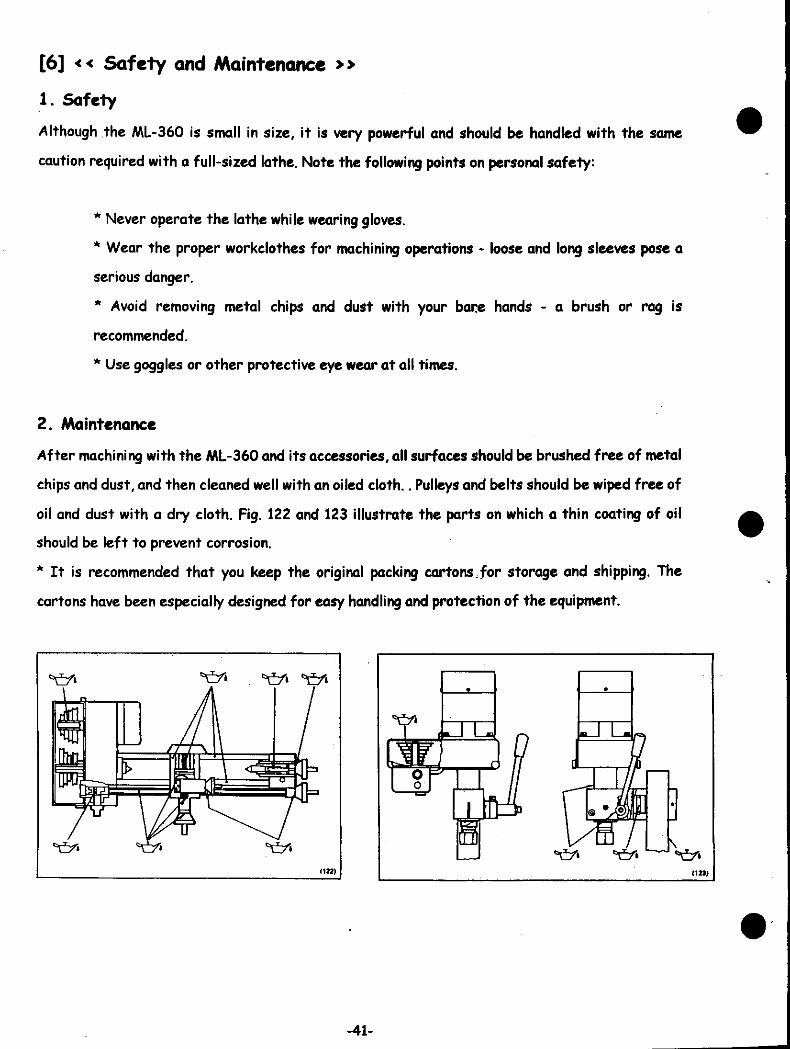
2. Maintenance
After machining with the ML-360 and its accessories, all surfaces should be brushed free of metal
chips and dust, and then cleaned well with an oiled cloth.. Pulleys and belts should be wiped free of
oil and dust with a dry cloth. Fig. 122 and 123 illustrate the parts on which a thin coating of oil
should be left to prevent corrosion.
* It is recommended that you keep the original packing cartons,for storage and shipping. The
cartons have been especially designed for easy handling and protection of the equipment.
-41-

[7] « Electric Wiring »
MINI - LATHE ML - 360
ON SWITCH H
OFF SHITCH
MOTOR (0.3KW.2P)
MILLING ATTACHMENT MA - 360
PLUGO O O
SWITCHJ
CONDENSERM) iMOTOR(120W,2P)
-42-

AA
I
V)VV
00*
[9] « ACCESSORIES »
Part
NumberNomenclature Description
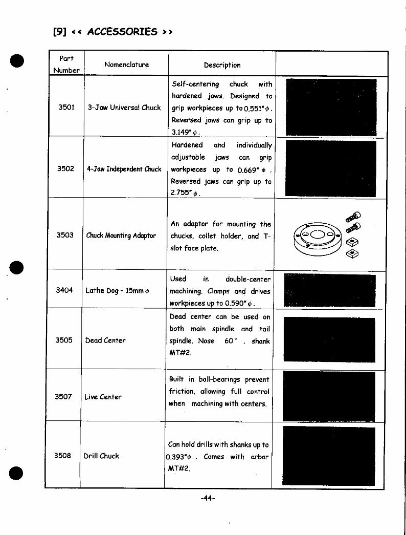
3501 3-Jaw Universal Chuck
Self-centering chuck with
hardened jaws. Designed to
grip workpieces up to 0.551" 0.
Reversed jaws can grip up to
3.149" 0-
Hardened and individually
adjustable jaws can grip
workpieces up to 0.669" * .
Reversed jaws can grip up to
2.755" 0.
3502 4-Jaw Independent Chuck
3503 Chuck Mounting Adaptor
An adaptor for mounting the
chucks, collet holder, and T-
slot face plate.
3404 Lathe Dog - 15mm
Used in double-center
machining. Clamps and drives
workpieces up to 0.590" 0.
3505 Dead Center
Dead center can be used on
both main spindle and tail
spindle. Nose 60° , shank
MT#2.
3507 Live Center
Built in ball-bearings prevent
friction, allowing full control
when machining with centers.
3508 Drill Chuck
Can hold drills with shanks up to
0.393*0 . Comes with arbor
-44-

Part
Number
3509
35310
35311
35317
3519
Nomenclature
Collet Holder
Collets
Automatic Feed/Thread
Cutting Attachment
Compound Slide
Slow Speed Attachment
Description
Used with the collet #35310.
A set including collet sizes 1/8,
3/16, 1/4, 5/16, 3/8, 1/2" and
blank. Used with the collet
chuck.
Used for automatic longitudinal
feed, including 0.0025 and
0.005. By changing gears, 31
different unified thread
pitches can be cut (Pitch rang
from 80 to 10 thread per inch).
Used for cutting tapers.
Turning scales graduated up to
45° on both sides, tool post
travels up to 2.047 in.
Used to lower the main spindle
speed to 80-170rpm. Effectice
when threading or machining
large diameters.
No.36W
• f t
t f f fNo. 35310
© if © ¥ © ¥ ©
-45-

Part
NumberNomenclature Description
3520 Steady Rest
Used to support the workpiece
when a center can not be used.
Largest holding diameter is
1.950" 0.
3521 Travelling Rest
Used to support thin or long
workpieces. Maximum
machining diameter is 1.950" 0.
3523T-slot Face Plate
1500
Useful when processing
irregularly-shaped workpieces
or workpieces too large for a
chuck, and for milling. Comes
with the Fixture (No. 3443).
3459 Round Tool Adaptor
To hold round cutting tools,
such as Nos. 3053, "3054, and
3056 to tool post.
3416 Cut Off Tool HolderFor holding the Cut Off Tool,
No. 3055.
3055 Cut Off Tool
Used for cutting- off and
grooving. Can be ground for
cutting external threads. Used
with the Cut Off Tool Holder,No.3416.
3070 Drill
A set of 1.5, 2.0, 2.5, 3.0, 3.3,
3.5, 4.0, 4.2, 4.5, 5.0, 5.5, 6.0,
and 6.5mm 0 drills
3071 Center DrillSet of 1.0, 1.5, and 2.0mm 0
drills.
-46-

Part
NumberNomenclature Description
3450Right-hand Finishing
Tool
For cylindrical and counterface
turning. Moves from right to
left.
3451 Roughing ToolFor cylindrical and step turning.
Moves from right to left.
3452 External Threading Tool For threading external screws.
3053 Boring Bar - 10mm*
For boring over 3/8"$.; Can
also be ground to be used for
grooving.
3054 Boring Bar - 6mm 0 For boring over 1/4" 0.
3056 Internal Threading Tool For cutting internal threads.
3060 Unground ToolA square bit, ready to be
ground for your specific needs.
35330 Milling Attachment
Useful for various milling
applications. Main spindle head' p f
can be swiveled 360 °
horizontally and vertically.
-47-

Part
NumberNomenclature Description
35331 Fine Feed Attachment
Used on the Milling attachment
(No. 35330), to allow fine feed
controlled with the handwheel.
Minimum graduation of O.OOlin.
35332 Milling Collet
Collet for the. milling
attachment. A set of 3 collets,
1/4,3/8,41/2-0.
* Standard Accessory.
35333 Drill Chuck- 10mm*
Used with the No. 35330 milling
attachment. Can hold
workpieces up to 0.393" 0 and
is useful with drilling
operations.
3534 Milling Table
Used mounted on the carriage.
Holds workpieces fixed with
the Fixture on the three T-
slots.
3535
Index Head with
Dividing Plate of 48
Divisions
For 2,3,4, 6, 8,12,16,24,448
divisions. Used with chucks
3501 and 3502, collet chuck
3509, and face plate 3523.
3536
3537
3538
Dividing Plate 30For 2, 3, 5, 6, 10, 15, 4 30
divisions.
Dividing Plate 36For 2, 3, 4, 6, 9, 12, 18, 4 36
divisions.
Dividing Plate 40For 2, 4, 5, 8, 10, 20, and 40
divisions.
-48-
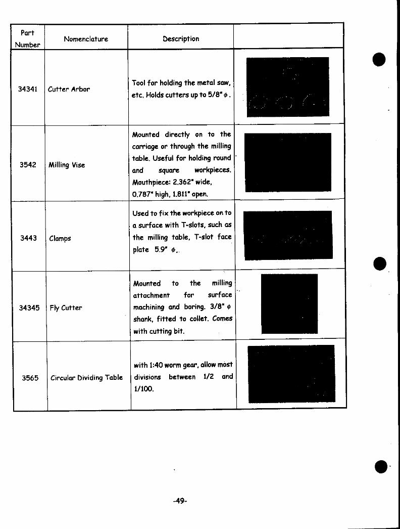
Part
NumberNomenclature Description
34341 Cutter ArborTool for holding the metal saw,
etc. Holds cutters up to 5/8" 0.
3542 Milling Vise
Mounted directly on to the
carriage or through the milting
table. Useful for holding round
and square workpieces.
Mouthpiece: 2.362" wide,
0.787" high, 1.811" open.
3443 Clamps
Used to fix the workpiece on to
a surface with T-slots, such as
the milling table, T-slot face
plate 5.9" </>..
34345 Fly Cutter
Mounted to the milling
attachment for surface
machining and boring. 3/8" 0
shank, fitted to collet. Comes
with cutting bit.
3565 Circular Dividing Table
with 1:40 worm gear, allow most
divisions between 1/2 and
1/100.
-49-
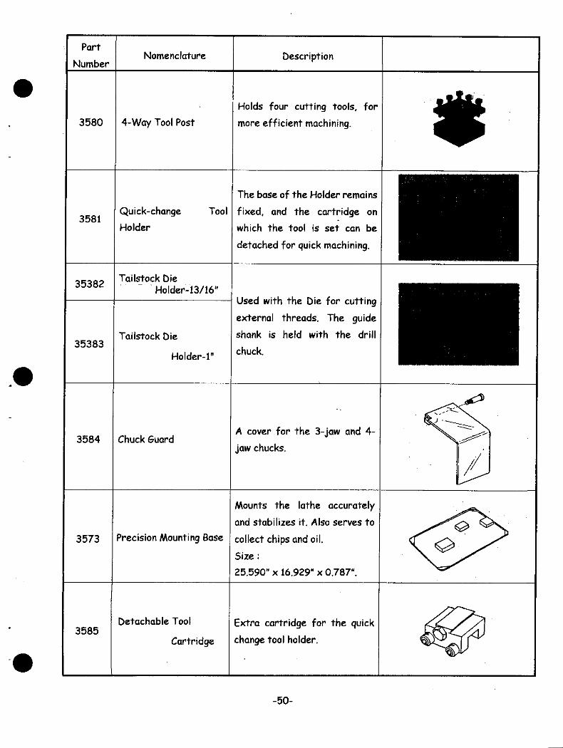
Part
NumberNomenclature Description
3580 4-Way Tool Post
Holds four cutting tools, for
more efficient machining.
3581Quick-change
Holder
Tool
The base of the Holder remains
fixed, and the cartridge on
which the tool is set can be
detached for quick machining.
35382
35383
Tai(stock DieHolder-13/16"
Tailstock Die
Holder-i"
Used with the Die for cutting
external threads. The guide
shank is held with the drill
chuck.
3584 Chuck GuardA cover for the 3-jaw and 4-
jaw chucks.
3573 Precision Mounting Base
Mounts the lathe accurately
and stabilizes it. Also serves to
collect chips and oil.
Size :
25.590" x 16.929" x 0.787".
3585Detachable Tool
Cartridge
Extra cartridge for the quick
change tool holder.
-50-

[10] « Parts List »
MINI-LATHE Ml-360
HeadstockNo.i2
3
4
5678910111213
14151617181920212223
2425262728
2930
3132
3334353637
383940
4142
4344
45464748
49
505152535455565758
Port Number353-0001353-0017353-0019353-0046353-0048353-0052353-0090353-009135-D000335-0000535-C000735-D001035-0001335-C001435-D001835-8003835-0003935-D004035-D004235-D004335-C004535-D004735-0005835-D006335-D0016
NomenclatureHead Stock 360Pulley GuardName PlateMotor Mounting PlateTable (Main Spindle Speed)MotorRating PlateWarning PlateMain Spindle KeyBearing CoverMain Spindle PulleyPulleyCounter Pulley ShaftCounter PulleyBush, 101413Main Spindle 2Tooth Washer AW06XTension PlateTension Pulley ShaftTension Plate PivotBulkhead 2Retaining RingTension Pulley 2Counter Pulley CollarKnob $28Taper Roller Bearing, HR32006 XJ-4Oil seal VB,Retaining Nut, AN06, MC-shaped Snap Ring, STW-10Washer, STW-FT, * 10 x 0.5V. Belt. K-21, Motor/Main SpindleV. Belt. K-16, Motor/Counter PulleyHex. Head Bolt, M8 x 12Allen Head Bolt, MS x 40Allen Head Bolt, MS x 12Allen Head Bolt, M5 x 10Set Screw, M6 x 8, Hollow EndSet Screw, M4 x 6, Hollow EndMachine Screw, Pan Head, Phillips, M4 x 10Machine Screw, Flat End, Phillips, M4 x 8Hex. Nut, MS, Cl. 1Hex. Nut, MS, CI.3Hex. Nut, M4, Cl. 1Washer, 0 8 x * 17 x 1.6tWasher, 0 8 x * 16.5 x 0.8t,Spring Washer, * 8, No. 2Allen Head Bolt, M4 x 10Allen Head Bolt, M4 x 16Hex. Head Bolt, Phillips, M4 x 10Washer, «4x09x0.8t.ON SwitchOFF SwitchRelaySwitch for Counter-Clockwise and Clockwise RotationPower Cable without PlugCable LockPower SwitchSpring Washer, 0 4, No.2
Quantityiiiiiiiiiiiiii31
1111
111
1
12
1
1
32
1134172
2
62
22
56
5112
1
1
1
1
1
1
1
1
1
1
-51-


BedNo.i2
34567
89101112131415
1617
18
192021
22
2324
Port Number353-0102353-0109353-0113353-0120353-012135-A010135-C010335-0010435-0010535-0010635-0010739-001 1235-D0016
NomenclatureLead Screw 360Calibrated Cone 51Lead Screw Counter MarkHandwheel 80Handle Knob 36Bed 360Lead Screw CoverClutch 360 - Lead ScrewPlain Bearing 360 ( Lead Screw 360)ClutchClutch Shaft 360Threaded CollarKnob #28Allen Head Bolt, M5 x 45 (5=16)Set Screw, M6 x 6, Hollow EndSet Screw, M6 x 12, Flat EndSet Screw, M4 x 6, Hollow EndMachine Screw, Philips, M3 x 6Hex. Nut, M6, Cl. 3Hex. Nut, M5, Cl. 2Cap Nut, MS, Type 3Washer, * 8 x * 15.5 x 0.5tRoll Pin,* 3x12Grooved Pin, 0 2 x 10, Type 0
Quantityiiiiiiiiiiiiiiiiiiiii2
11
Toilstock
No.i2
34
5678
9101112
131415
1617181920
Port Number353-0302353-0303353-0310353-031135-B030135-0030435-00305353-010935-00210
35053507
NomenclatureTa.l Stock Spindle 24Toilstock Spindle Feed Lead Screw 360Handwheel 52Handle Knob 27Toilstock 360Plain Bearing 360 (Tailstock Spindle Feed Lead Screw 360)Tailstock Fastening Square NutCalibrated Cone 51Threaded CollarAllen Head Bolt, MS x 30Allen Head Bolt, M6 x 22Allen Head Bolt, M4 x 35 (5=14)Set Screw, M6 x 10, Hollow EndHex. Nut, M6, Cl. 1Hex. Nut, M4, Cl. 2Cap Nut, M8, Type 3Washer, 0 8 x 0 15.5 x 0.5tGrooved Pin, 04x8, Type BOead Center 360Live Center 360
Quantityiiiiiiiiiiiiiiii31
1
1
-53-
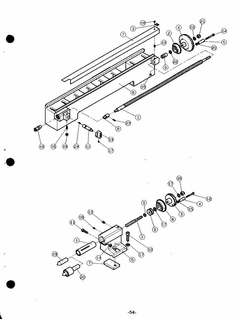
-54-

Taper Turning Attachment & Tool Post Carriage
No.i2
345
6789101112131415
16
1718
19202122
23
2425
26
2728
29
303132
3334353637
383940
41424344
4546
474849
Part Number353-0206353-0207353-020835-B020135-D020234-D020335-C020335-0020435-D0210353-0109353-0120353-0121
35317-000135317-00073517-C00023517-000043517-0000535-00204353-0310353-0311353-010935-002103517-000083580-C00013580-000023580-00005
NomenclatureCross Feed Lead Screw 360Special Nut 360 (Cross Feed Lead Screw 360)Special Nut ( Lead Screw 360)Tool Post Carriage 360Tool Post Carriage Back Plate 360Carriage Fastening Square NutCross Feed Table 360ShimThreaded CollarCalibrated Cone 51Handwheel 80Handle Knob 36Allen Head Bolt, M6 x 20Allen Head Bolt, M5 x 45 (5=16)Allen Head Bolt, M4 x 12Allen Head Bolt, M3 x 12Set Screw, M6 x 6, Hollow EndSet Screw, M4 x 8, Hollow EndSet Screw, W3 x 15, Hollow EndAllen Head Button Bolt, M6 x 14Machine Screw, Phillips, M4 x 8Hex. Nut, AA5, Cl. 2Hex. Nut, M3. Cl. 1Cap Nut, M8, Type 3Washer, «8 x«15.5x0.5tSwivel Base 360Lead ScrewTaper Feed TableRetainer PlateEccentric BushShimHandwheel 52 --Handle Knob 25Calibrated Cone 51Threaded CollarSquare Nut II4 - Way Toot PostPivotFastening NutAllen Head Bolt, M6 x 20Allen Head 'Bolt, M4 x 35 (3=14)Allen Head Bolt, M4 x 12Allen Head Bolt, M3 x 12Set Screw, M3 x 12, Hollow EndHex. Nut, M4, Cl. 2Hex. Nut, M3. Cl. 1Cap Nut, M8, Type 3Washer, 0 8 x « 15.5 x 0.5tWasher, $6 x*11.5 x0.8t
Quantity1111111111111i2
1
2
2
3211
312
1
11
1
1111111111
1012
1
31
3121
-55-
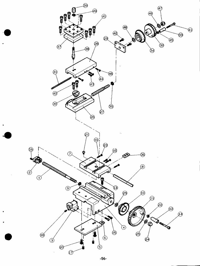
-56-

No.i2
3456
78
91011
12
131415161718
192021
22
232425
262728
29303132
33
3435
3637383940
4142
434445
464748495051525354555657585960
61
6263
6465
Port Number35330-000135330-000235330-000435330-000635330-000835330-005235330-008035330-009035330-00913530-C00033530-00005
3530-B00073530-D00093530-000103530-D00113530-000123530-000133530-D00143530-000153530-C00163530-C00173530-D00183530-000193530-B00203530-C00213530-C00223530-B00233430-0000534-002835330-00923530-C0024
NomenclatureMain Spindle HeadMain Spindle Quill 45Pinion Shaft 360MA (Main Spindle Feed)Motor Bracket 360MASwitch Plate 360MAMotorReference Scale (Main Spindle Feed)Rating PlateWarning PlateMain Spindle 360MALever (Main Spindle Feed)Pulley Guard 360MABack Plate 360MAPartition 360MACoiled Spring 360MA (Main Spindle Quill)Guide Screw RHGuide Screw LHPlate Nut (Main Spindle Quill)Motor Pulley 360MACounter Pulley 360MAMain Spindle Pulley 360MAShaft 360MA (Counter Pulley)Spring Collar (Main Spindle Quill)Carriage 360MA (Milling Head)Reference Scale 360MA (Lateral Swing)Vertical Column 360MAColumn Mounting Block 360MAStop Ring 26Motor GuardSwitch GuardTable 360MA (Main Spindle Speed)Ball Bearing, 6003ZZC-shaped Snap Ring, Inner Use, RTW-30Washer, STW-FT, *Bx0.5Primary Power Transmit Belt, 5M - 325Secondary Power Transmit Belt, 5M - 375Rubber CapBush.«8x«12xl2LRivet, Round Head, Grooved, M3 x 10Wave Washer, 4 17Roll Pin, 03x12Hex. Head Bolt, M6 x 15Allen Head Bolt, M8 x 50Allen Head Bolt, MS x 35Allen Head Bolt, M5 x 20Allen Head Bolt. M5 x 8Set Screw, M6 x 20, Flat EndSet Screw, M4 x 4, Hollow EndSelf Tapping Screw, M4 x 10Machine Screw, Phillips, M3 x 12,Hex. Nut, M5, Cl. 1Hex. Nut, M3. Cl. 1Washer, *8x*17xl.6tWasher, «6 x*11.5 x l.6tWasher, «5x«10xltWasher, *17x*32x2.6tSpring Washer, # 5, No. 2Allen Head Bolt, M4x 10Hex. Head Bolt. Phillips, M4 x 10Hex. Nut, M4, Cl. 1Washer, «4x«9x0.8tRubber #270SwitchPower Cable without PluaCable Lock
Quantityiiiiiiiiiiiiiiiiiiiiiiiiiiiiiii2
2
2111222
22
54
42
1141
41428142
1
1
21111
-57-
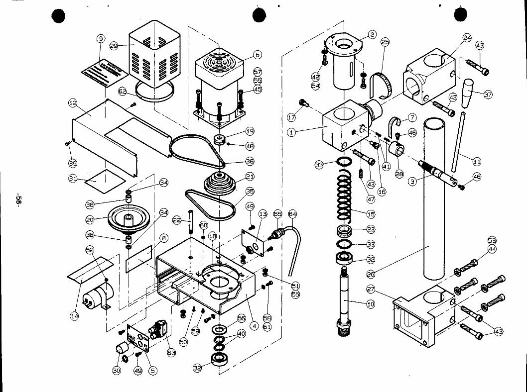
CJ100
£r ^J£

Exclusively imported & Distributed by
SAKAI MACHINE TOOLS MFG., INC.50 Main Street-Suite #1000 White Plains. NY 10606
Phone 914-682-6816 Fax 914-682-2110
Manufactured by
SAKAI SPECIAL CAMERA MFG. CO., LTD.Head Office
1-2-8 Hattori-Honmachi, Toyonaka City, OSAKA 561-0852 JAPAN

[1] Installing Pulley Guard:
1. The hinges on the pulley guard are attached to the
motor mounting plate by means of four Philips head
screws.
Position the pulley guard so that the holes in the hinges
ore in line with the threaded holes in the motor mounting
plate.
3. Use a Philips screwdriver to tighten the four screws to
secure the hinges and the cover.
4. Check the alignment of the cover to be sure that it
clears the top edge of the motor mounting plate.
5. When the pulley guard closes freely, screw in the socket
head capscrew from the front to secure the pulley guard
in the closed position.
6. Safety note: The pulley guard must always be closed
and properly secured when running the ML-360 Mini
Lathe to ensure that personal injury does not occur to
the operator because of the belts, pulleys, and gears in
the Lathe operating mechanism.
2.
3.
Mounting the Handle Knob on the Longitudinal Handwheel:
The knob B is attached to the hand wheel by means of a
socket head cap screw which passes through the knob
and is screwed into the tapped hole in the handwheel.
Screw the nut on the socket head screw between the
handle knob and the handwheel.
After screwing the socket head screw into the
handwheel, adjust the nut and tighten it with the 8 mm.
wrench to allow 0,5 mm. (approximately 1/64") clearance
between the nut and the handle knob.
Handle Knob (B)