Instruction for the sonography of the facial muscles · Margo infraorbitalis . Approach. Upper lip,...
32
Instruction for the sonography of the facial muscles Gerd Fabian Volk, Basel 2018 based on the German version from Maik Sauer, Jena 2013
Transcript of Instruction for the sonography of the facial muscles · Margo infraorbitalis . Approach. Upper lip,...
Instructions for Sonography of Facial Muscles
Instruction for the sonography of the facial muscles
Gerd Fabian Volk, Basel 2018 based on the German version from Maik Sauer, Jena 2013
Table of contents
1. Introduction 2 2. Information on the conduction of the examination 2 3. Position of the marker on the ultrasound transducer 3 4. Position and handling of the ultrasound transducer 4 5. Anatomy of the mimic muscles 4 6. Anatomy of the chewing muscles 7 7. Sonographic representation of the facial muscles 8
7.1 Venter frontalis, M. occipitofrontalis 8 7.2 M. corrugator supercilii 10 7.3 M. procerus 12 7.4 M. orbicularis oculi 13 7.5 M. nasalis 15 7.6 Mm. mentales 16 7.7 M. orbicularis oris 17 7.8 M. depressor anguli oris / M. depressor labii inferioris 18 7.9 M. risorius 20 7.10 M. zygomaticus major 21 7.11 M. zygomaticus minor 22 7.12 M. levator labii superioris 23 7.13 M. levator labii superioris alaeque nasi 24 7.14 M. buccinator 25
8. Sonographic cut of the chewing muscles 26 8.1 M. temporalis 26 8.2 M. masseter 27
9. Power Doppler - Sonography of the facial arteries 28 9.2 A. temporalis profunda anterior 30 9.3 A. labialis superior 31
1 Instructions for sonography of facial muscles
1. Introduction This instruction for sonography of the facial muscles is meant to help the interested sonography users to better understand the partly very complex sonographic cross sections of the mimic and chewing musculature and to reproduce them themselves. It is also meant to help with the evaluation of the captured sonographic data. Due to the special anatomy of the facial musculature it is not always easy to differentiate single facial muscles against the surrounding fat and connective tissue. All sonographic pictures will be accompanied by a schematic drawing below to make things clearer. To clarify the dynamic changes of the different muscles in motion, each sonographic picture in relaxation will be accompanied by a picture of maximum arbitrary contraction. In addition to the pictures of the muscles in relaxation and contraction, there is also a batch of pictures which show some examples of areas which were encircled wrongly to avoid misunderstandings. The anatomic structures marked with numbers will be named and explained underneath the appropriated pictures. To simplify the orientation and to clearly arrange the atlas, only pictures of the right face half were used. Furthermore, so called markers were used. Their function and meaning will be illustrated in detail in section 3.
2. Information on the conduction of the examination Always use a sufficient amount of ultrasound gel to achieve an optimal skin coupling as well as a prevention of compression on the superficial muscles and vessels. The usage of standoff pads has turned out unsuitable in practice. Standoff pads are often unhandy for the examiner and are uncomfortable for the patient. The image quality only improved insignificantly. If the dynamic characteristics of the muscles shall be assessed, it turned out to be helpful to practice the appropriated movements before the examination. The movements shall be explained in detail and be demonstrated by the examiner. As it is quite hard for many people to consciously perform mimic movements, we recommend the use of a mirror in the training phase and also during the examination itself. Contractions of the appropriate target muscle might facilitate the clear identification of single muscles for the examiner. As the mimic muscles of elderly and/or obese people often contain a lot of connective and fat tissue and thus appear hyperechoic, the identification by contraction is particularly important. The examiner should pay special attention to the fact, that the patient performs the required movement. If the perfusion shall be determined, it should take part before the contraction. Thus changes in blood flow by vascular compression or vasoactive mediators can be minimized.
2 Instructions for sonography of facial muscles
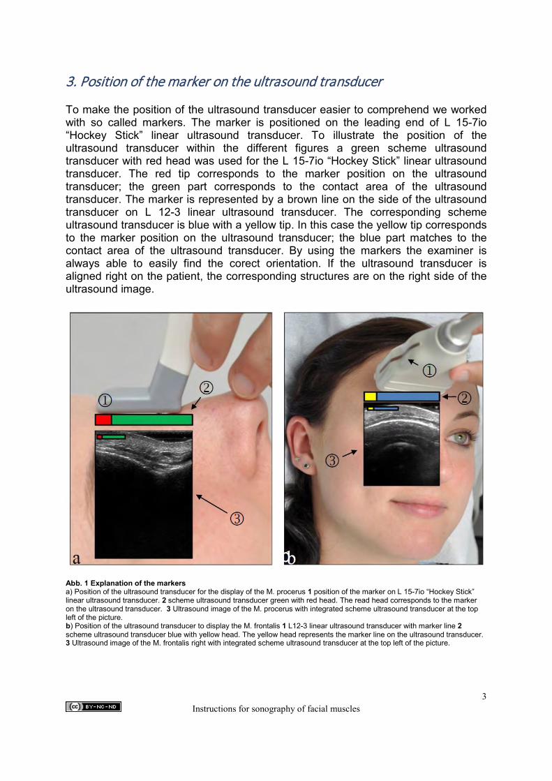
3. Position of the marker on the ultrasound transducer To make the position of the ultrasound transducer easier to comprehend we worked with so called markers. The marker is positioned on the leading end of L 15-7io “Hockey Stick” linear ultrasound transducer. To illustrate the position of the ultrasound transducer within the different figures a green scheme ultrasound transducer with red head was used for the L 15-7io “Hockey Stick” linear ultrasound transducer. The red tip corresponds to the marker position on the ultrasound transducer; the green part corresponds to the contact area of the ultrasound transducer. The marker is represented by a brown line on the side of the ultrasound transducer on L 12-3 linear ultrasound transducer. The corresponding scheme ultrasound transducer is blue with a yellow tip. In this case the yellow tip corresponds to the marker position on the ultrasound transducer; the blue part matches to the contact area of the ultrasound transducer. By using the markers the examiner is always able to easily find the corect orientation. If the ultrasound transducer is aligned right on the patient, the corresponding structures are on the right side of the ultrasound image.
Abb. 1 Explanation of the markers a) Position of the ultrasound transducer for the display of the M. procerus 1 position of the marker on L 15-7io “Hockey Stick” linear ultrasound transducer. 2 scheme ultrasound transducer green with red head. The read head corresponds to the marker on the ultrasound transducer. 3 Ultrasound image of the M. procerus with integrated scheme ultrasound transducer at the top left of the picture. b) Position of the ultrasound transducer to display the M. frontalis 1 L12-3 linear ultrasound transducer with marker line 2 scheme ultrasound transducer blue with yellow head. The yellow head represents the marker line on the ultrasound transducer. 3 Ultrasound image of the M. frontalis right with integrated scheme ultrasound transducer at the top left of the picture.
b
3 Instructions for sonography of facial muscles

4. Position and handling of the ultrasound transducer The ultrasound transducer shall always be put vertically on the skin surface. Otherwise the respective muscle will be oblique cut and the corresponding measuring values will be useless. The display of vessels is an exception from the above described handling of the ultrasound transducer. Due to the variable course of vessels it might be necessary to swivel the ultrasound transducer based on the initial position through the cut of the vessel, i.e. to change the angle of the ultrasound transducer to the skin surface. Thus it is possible to show a straight, axial cut of the vessel along the course of the vessel. 5. Anatomy of the mimic muscles Tab. 1 Anatomy of the facial musculature (by Zilles et al. 2010) Muscle Origin/Approach Innervation/blood supply Function Muscles of the skullcap M. epicranius M. occipitofrontalis
▪ Venter frontalis
▪ Venter occipitalis (M. occipitalis)
Origin over the tendons of adjacent muscles in the range of pars nasalis of Os frontale Approach Galea aponeurotica Origin Linea nuchalis suprema Approach Galea aponeurotica
Innervation
▪ Rr. temporalis of the N. facialis
Blood supply ▪ A. supraorbitalis ▪ A. supratrochlearis ▪ A. lacrimalis ▪ R. frontalis of the
A. temporalis superficialis
Innervation ▪ R. occipitalis of the
N. auricularis posterior of the N. facialis
Blood supply ▪ A. occipitalis
Shifting the scalp Raising the eyebrows and the forehead skin
M. temporoparietalis
Origin Fascia temporalis Approach Galea aponeurotica
Innervation ▪ Rr. temporalis of the
N. facialis Blood supply
▪ A. temporalis superficialis
no appreciable function
Muscles in the range of the eye socket and the palpebral fissure M. orbicularis oculi
▪ Pars orbitalis
▪ Pars palpebralis
▪ Pars lacrimalis (Horner-muscle)
Origin Crista lacrimalis und Proc. frontalis der Maxilla Approach over the Raphe palpebralis lateralis on Os zygomaticum Origin Lig. palpebrale mediale Approach Lig. palpebrale laterale Origin Crista lacrimalis of the Os lacrimale Approach Canaliculi lacrimales into the Pars palpebralis
Innervation
▪ Rr. temporalis ▪ Rr. zygomatici of the
N. facialis Blood supply
▪ A. facialis ▪ R. frontalis of the
A. temporalis superficialis ▪ A. infraorbitalis of the
A. maxillaris ▪ A. supraorbitalis,
A. lacrimalis and A. supratrochlearis of the A. ophthalmica
Firm closure of the palpebral fissure Closure of the palpebral fissure, participation on blink and stabilisation of the lower eyelid for forming the “Tränensee” Stimulation of the lacrimation Outflow of the lacrimal fluid
M. corrugator supercilii
Origin Os frontale above the Sutura frontomaxillaris, Glabella, Arcus superciliaris Approach Skin above the middle third of the eyebrow, Galea aponeurotica
Innervation ▪ Rr. temporalis of the
N. facialis Blood supply
▪ A. supraorbitalis and A. supratrochlearis of the A. ophthalmica
▪ R. frontalis of the A. temporalis superficialis
Shifting the eyebrow skin downwards medial
M. depressor supercilii
Origin Os frontale Approach medial part of the eyebrow
Innervation ▪ R. temporalis of the N.
facialis Blood supply
▪ Aa. supratrochlearis and supraorbitalis of the A.
Shifting the skin above the nasal root to a cross fold
4 Instructions for sonography of facial muscles
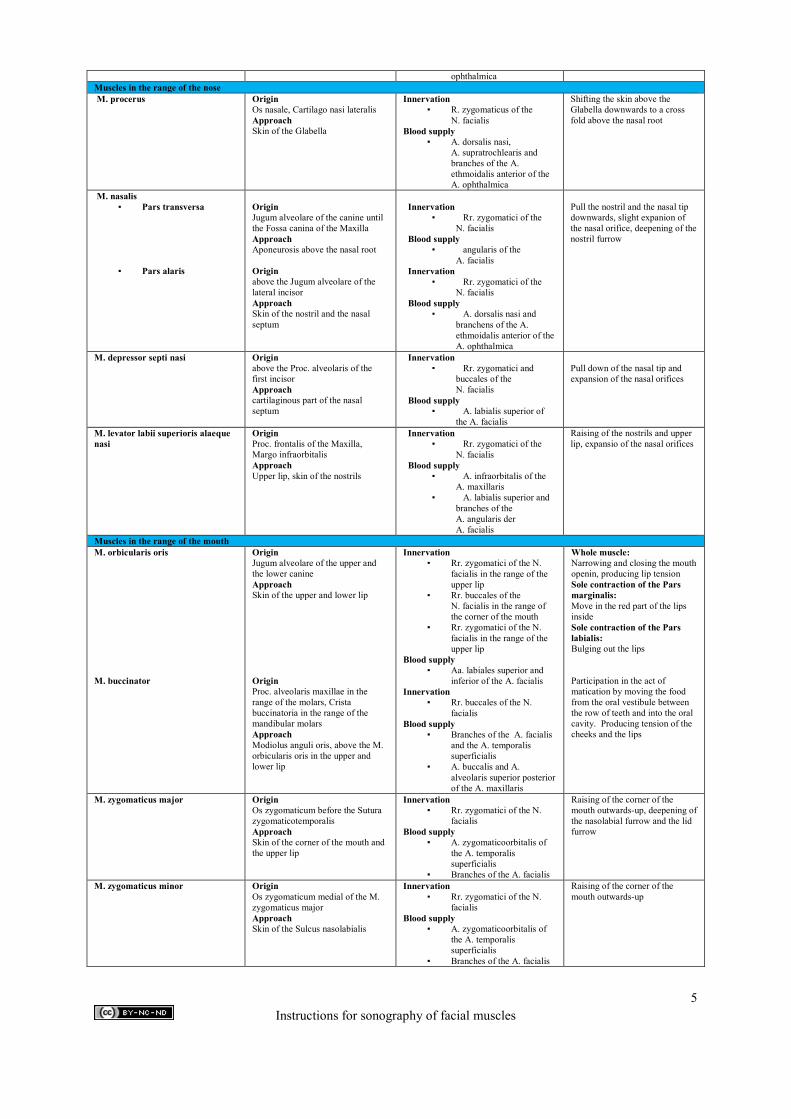
ophthalmica Muscles in the range of the nose M. procerus
Origin Os nasale, Cartilago nasi lateralis Approach Skin of the Glabella
Innervation ▪ R. zygomaticus of the
N. facialis Blood supply
▪ A. dorsalis nasi, A. supratrochlearis and branches of the A. ethmoidalis anterior of the A. ophthalmica
Shifting the skin above the Glabella downwards to a cross fold above the nasal root
M. nasalis ▪ Pars transversa
▪ Pars alaris
Origin Jugum alveolare of the canine until the Fossa canina of the Maxilla Approach Aponeurosis above the nasal root Origin above the Jugum alveolare of the lateral incisor Approach Skin of the nostril and the nasal septum
Innervation
▪ Rr. zygomatici of the N. facialis
Blood supply ▪ angularis of the
A. facialis Innervation
▪ Rr. zygomatici of the N. facialis
Blood supply ▪ A. dorsalis nasi and
branchens of the A. ethmoidalis anterior of the A. ophthalmica
Pull the nostril and the nasal tip downwards, slight expanion of the nasal orifice, deepening of the nostril furrow
M. depressor septi nasi
Origin above the Proc. alveolaris of the first incisor Approach cartilaginous part of the nasal septum
Innervation ▪ Rr. zygomatici and
buccales of the N. facialis
Blood supply ▪ A. labialis superior of
the A. facialis
Pull down of the nasal tip and expansion of the nasal orifices
M. levator labii superioris alaeque nasi
Origin Proc. frontalis of the Maxilla, Margo infraorbitalis Approach Upper lip, skin of the nostrils
Innervation ▪ Rr. zygomatici of the
N. facialis Blood supply
▪ A. infraorbitalis of the A. maxillaris
▪ A. labialis superior and branches of the A. angularis der A. facialis
Raising of the nostrils and upper lip, expansio of the nasal orifices
Muscles in the range of the mouth M. orbicularis oris M. buccinator
Origin Jugum alveolare of the upper and the lower canine Approach Skin of the upper and lower lip Origin Proc. alveolaris maxillae in the range of the molars, Crista buccinatoria in the range of the mandibular molars Approach Modiolus anguli oris, above the M. orbicularis oris in the upper and lower lip
Innervation ▪ Rr. zygomatici of the N.
facialis in the range of the upper lip
▪ Rr. buccales of the N. facialis in the range of the corner of the mouth
▪ Rr. zygomatici of the N. facialis in the range of the upper lip
Blood supply ▪ Aa. labiales superior and
inferior of the A. facialis Innervation
▪ Rr. buccales of the N. facialis
Blood supply ▪ Branches of the A. facialis
and the A. temporalis superficialis
▪ A. buccalis and A. alveolaris superior posterior of the A. maxillaris
Whole muscle: Narrowing and closing the mouth openin, producing lip tension Sole contraction of the Pars marginalis: Move in the red part of the lips inside Sole contraction of the Pars labialis: Bulging out the lips Participation in the act of matication by moving the food from the oral vestibule between the row of teeth and into the oral cavity. Producing tension of the cheeks and the lips
M. zygomaticus major
Origin Os zygomaticum before the Sutura zygomaticotemporalis Approach Skin of the corner of the mouth and the upper lip
Innervation ▪ Rr. zygomatici of the N.
facialis Blood supply
▪ A. zygomaticoorbitalis of the A. temporalis superficialis
▪ Branches of the A. facialis
Raising of the corner of the mouth outwards-up, deepening of the nasolabial furrow and the lid furrow
M. zygomaticus minor
Origin Os zygomaticum medial of the M. zygomaticus major Approach Skin of the Sulcus nasolabialis
Innervation ▪ Rr. zygomatici of the N.
facialis Blood supply
▪ A. zygomaticoorbitalis of the A. temporalis superficialis
▪ Branches of the A. facialis
Raising of the corner of the mouth outwards-up
5 Instructions for sonography of facial muscles
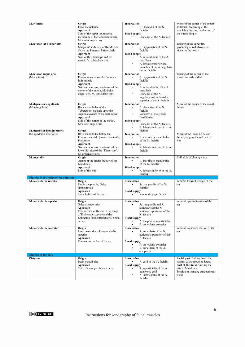
M. risorius
Origin Facia masseterica Approach Skin of the upper lip, mucous membrane of the Vestibulum oris, Modiolus anguli oris
Innervation ▪ Rr. buccales of the N.
facialis Blood supply
▪ Branches of the A. facialis
Move of the corner of the mouth to lateral, deepening of the nasolabial furrow, production of the cheek dimple
M. levator labii superioris
Origin Margo infraorbitalis of the Maxilla above the Foramen infraorbitale Approach Skin of the Oberlippe and the nostril, M. orbicularis oris
Innervation ▪ Rr. zygomatici of the N.
facialis Blood supply
▪ A. infraorbitalis of the A. maxillaris
▪ A. labialis superior and branches of the A. angularis der A. facialis
Raising of the upper lip, producing a fold above and sidewise the nostril
M. levator anguli oris (M. caninus)
Origin Fossa canina below the Foramen infraorbitale Approach Skin and mucous membrane of the corner of the mouth, Modiolus anguli oris, M. orbicularis oris
Innervation ▪ Rr. zygomatici of the N.
facialis Blood supply
▪ A. infraorbitalis of the A. maxillaris
▪ Branches of the A. angularis and A. labialis superior of the A. facialis
Raising of the corner of the mouth cranial-medial
M. depressor anguli oris (M. triangularis) M. depressor labii inferioris (M. quadratus inferioris)
Origin Basis mandibulae of the Tuberculum mentale up to the Jugum alveolare of the first molar Approach Skin of the corner of the mouth, Modiolus anguli oris Origin Basis mandibulae below the Foramen mentale (connection to the Platysma) Approach Skin and mucous membrane of the lower lip, skin of the “Kinnwulst”, M. orbicularis oris
Innervation ▪ Rr. buccales of the N.
facialis ▪ variable: R. marginalis
mandibulae Blood supply
▪ Branches of the A. facialis ▪ A. labialis inferior of the A.
facialis Innervation
▪ R. marginalis mandibulae of the N. facialis
Blood supply ▪ A. labialis inferior of the A.
facialis
Move of the corner of the mouth below Move of the lower lip below-lateral, bulging the red part of lips
M. mentalis
Origin Jugum of the laterla incisor of the Mandibula Approach Skin of the chin
Innervation ▪ R. marginalis mandibulae
of the N. facialis Blood supply
▪ A. labialis inferior of the A. facialis
Shift skin of chin upwards
Muscles in the range of the outer ear M. auricularis anterior
Origin Fascia temporalis, Galea aponeurotica Approach Spina helicis of the ear
Innervation ▪ Rr. temporalis of the N.
facialis Blood supply
▪ temporalis superficialis
minimal forward tension of the ear
M. auricularis superior
Origin Galea aponeurotica Approach Rear surface of the ear in the range of Eminentia scaphae and the Eminentia fossae triangularis, Spina helicis
Innervation ▪ Rr. temporalis and R.
auricularis of the N. auricularis posterior of the N. facialis
Blood supply ▪ A. temporalis superficialis ▪ A. auricularis posterior
minimal upward tension of the ear
M. auricularis posterior
Origin Proc. mastoideus, Linea nuchalis superior Approach Eminentia conchae of the ear
Innervation ▪ R. auricularis of the N.
auricularis posterior of the N. facialis
Blood supply ▪ A. auricularis posterior ▪ R. auricularis of the A.
occipitalis
minimal backward tension of the ear
Muscles of the neck Platysma
Origin Basis mandibulae Approach Skin of the upper thoracic area
Innervation ▪ R. colli of the N. facialis
Blood supply ▪ R. superficialis of the A.
transversa colli ▪ A. submentalis of the A.
facialis
Facial part: Pulling down the corners of the mouth to lateral Part of the neck: Shifting the skin to Mandibula Tension of skin and subcutaneous tissue
6 Instructions for sonography of facial muscles
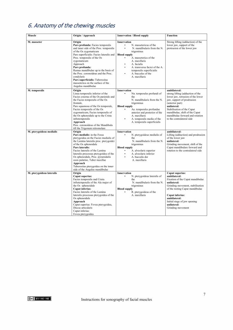
6. Anatomy of the chewing muscles Muscle Origin / Approach
Innervation / Blood supply Function
M. masseter Origin Pars profunda: Facies temporalis and inner side of the Proc. temporalis of the Os zygomaticum Pars superficialis: Facies lateralis and Proc. temporalis of the Os zygomaticum Approach Pars profunda: Ramus mandibulae up to the basis of the Proc. coronoideus and the Proc. condylaris Pars superficialis: Tuberositas masseterica on the surface of the Angulus mandibulae
Innervation ▪ N. massetericus of the ▪ N. mandibularis from the N.
trigeminus Blood supply
▪ A. masseterica of the A. maxillaris
▪ A. facialis ▪ A. transversa faciei of the A.
temporalis superficialis ▪ A. buccales of the
A. maxillaris
Strong lifting (adduction) of the lower jaw, support of the protrusion of the lower jaw
M. temporalis
Origin Linea temporalis inferior of the Facies externa of the Os parietale and the Facies temporalis of the Os frontale, Pars squamosa of the Os temporale, Facies temporalis of the Os zygomaticum, Facies temporalis of the Os sphenoidale up to the Crista infratemporalis Approach Proc. coronoideus of the Mandibula till the Trigonum retromolare
Innervation ▪ Nn. temporales profundi of
the N. mandibularis from the N. trigeminus
Blood supply ▪ Aa. temporales profundae
anterior and posterior of the A. maxillaris
▪ A. temporalis media of the A. temporalis superficialis
ambilateral: strong lifting (adduction of the lower jaw, retrusion of the lower jaw, support of prodrusion (anterior part) unilateral: Stabilisation of the Caput mandibulae, shift of the Caput mandibulae forward and rotation to the contralateral side
M. pterygoideus medialis
Origin Pars medialis: in the Fossa pterygoidea on the Facies medialis of the Lamina lateralis proc. pterygoidei of the Os sphenoidale Pars lateralis: Facies lateralis of the Lamina lateralis processus pterygoidea of the Os sphenoidale, Proc. pyramidalis ossis palatine, Tuber maxillae Approach Tuberositas pterygoidea on the inner side of the Angulus mandibulae
Innervation ▪ N. pterygoideus medialis of
the N. mandibularis from the N. trigeminus
Blood supply ▪ A. alveolaris superior ▪ A. alveolaris inferior ▪ A. buccalis der
A. maxillaris
ambilateral: Lifting (adduction) and prodrusion of the lower jaw unilateral: Grinding movement, shift of the Caput mandibulare forward and rotation to the contralateral side
M. pterygoideus lateralis
Origin Caput superius: Facies temporalis and Crista infratemporalis of the Ala major of the Os sphenoidale Caput inferius: Facies lateralis of the Lamina lateralis processus pterygoidea of the Os sphenoidale Approach Caput superius: Fovea pterygoidea, Discus articularis Caput inferius: Fovea pterygoidea
Innervation ▪ N. pterygoideus lateralis of
the N. mandibularis from the N. trigeminus
Blood supply ▪ R. pterygoideus of the
A. maxillaris
Caput superius: ambilateral: Fixation of the Caput mandibulae unilateral: Grinding movement, stabilisation of the resting Caput mandibulae Caput inferius: ambilateral: Initial stage of jaw opening unilateral: Grinding movement
7 Instructions for sonography of facial muscles
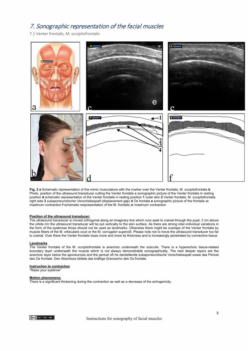
7. Sonographic representation of the facial muscles 7.1 Venter frontalis, M. occipitofrontalis
Fig. 2 a Schematic representation of the mimic musculature with the marker over the Venter frontalis, M. occipitofrontalis b Photo, position of the ultrasound transducer cutting the Venter frontalis c sonographic picture of the Venter frontalis in resting position d schematic representation of the Venter frontalis in resting position 1 outer skin 2 Venter frontalis, M. occipitofrontalis right side 3 subaponeurotischer Verschiebespalt (displacement gap) 4 Os frontale e sonographic picture of the frontalis at maximum contraction f schematic respresentation of the M. frontalis at maximum contraction Position of the ultrasound transducer: The ultrasound transducer is moved orthogonal along an imaginary line which runs axial to cranial through the pupil. 2 cm above the orbita rim the ultrasound transducer will be put vertically to the skin surface. As there are strong inter-individual variations in the form of the eyebrows those should not be used as landmarks. Otherwise there might be overlaps of the Venter frontalis by muscle fibers of the M. orbicularis oculi or the M. corrugator supercilii. Please note not to move the ultrasound transducer too far to cranial. Over there the Venter frontalis loses more and more its thickness and is increasingly penetrated by connective tissue. Landmarks The Venter frontalis of the M. occipitofrontalis is anechoic underneath the subcutis. There is a hyperechoic tissue-related boundary layer underneath the muscle which is not always demonstrable sonographically. The next deeper layers are the anechoic layer below the aponeurosis and the periost oft he darstellende subaponeurotische Verschiebespalt sowie das Periost des Os frontale. Den Abschluss bildete das kräftige Grenzecho des Os frontale. Instruction to contraction “Raise your eyebrow” Motion phenomena: There is a significant thickening during the contraction as well as a decrease of the echogenicity.
e
c
8 Instructions for sonography of facial muscles
Information: The ultrasound transducer should be put on without pressure as the muscles will otherwise be compressed and the measured values might be significantly distorted. To compensate the contour of the skull it is important to use a lot of gel. Occasionally significant septations of the muscle occur. The request for contraction can facilitate the evaluation of the largest diameter a lot. The above described periost directly above the Os frontale shall also thicken during contraction. This is not caused by muscle fibers but by a kind of traction in the direction of the skin surface by the contracting Venter frontalis. Interpretation of errors There might be overlaps of the Venter frontalis by muscle fibers of the M. orbicularis oculi or the M. corrugator supercilii if the ultrasound transducer is put on wrong. Evaluation of the ultrasonic scan of m. orbitofrontalis venter frontalis: This muscle is a very long muscle. Because of that you cannot capture it entirely in the ultrasonic scan. Therefore you only measure the diameter of the muscle at its thickest part. That means that one does not have to encircle the muscle because the area measured does not match with the real size of the muscle. The decision about the thickest part is made in relaxation. In contraction it has to be measured at the same position as in relaxation.
9 Instructions for sonography of facial muscles
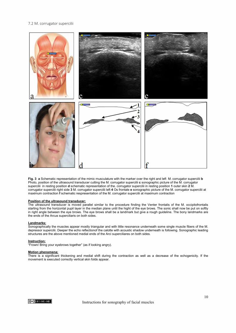
7.2 M. corrugator supercilii
Fig. 3 a Schematic representation of the mimic musculature with the marker over the right and left M. corrugator supercilii b Photo, position of the ultrasound transducer cutting the M. corrugator supercilii c sonographic picture of the M. corrugator supercilii in resting position d schematic representation of the. corrugator supercilii in resting position 1 outer skin 2 M. corrugator supercilii right side 3 M. corrugator supercilii left 4 Os frontale e sonographic picture of the M. corrugator supercilii at maximum contraction f schematic respresentation of the M. corrugator supercilii at maximum contraction Position of the ultrasound transducer: The ultrasound transducer is moved parallel similar to the procedure finding the Venter frontalis of the M. occipitofrontalis starting from the horizontal pupil layer in the median plane until the hight of the eye brows. The sonic shall now be put on softly in right angle between the eye brows. The eye brows shall be a landmark but give a rough guideline. The bony landmarks are the ends of the Arcus superciliaris on both sides. Landmarks: Sonographically the muscles appear mostly triangular and with little resonance underneath some single muscle fibers of the M. depressor supercilii. Deeper the echo reflectionof the calotte with acoustic shadow underneath is following. Sonographic leading structures are the above mentioned medial ends of the Arci superciliares on both sides. Instruction: “Frown/ Bring your eyebrows together” (as if looking angry). Motion phenomena: There is a significant thickening and medial shift during the contraction as well as a decrease of the echogenicity. If the movement is executed correctly vertical skin folds appear.
10 Instructions for sonography of facial muscles
Information: To compensate the contour of the skull it is important to use a lot of gel. The ultrasound transducer shall further on be put on without pressure. The M. corrugator supercilii is upwards differentiated by some hyperechoic connective tissue fibers from the above lying M. depressor supercilii. Interpretation of errors: The muscle can be clearly identified by contraction. If the ultrasound transducer is put on too far cranial the muscle can be overlapped by fibers of the M. frontalis. If the ultrasound transducer is put on too far caudal there will appear the cross sections of the M. levator labii superioris alaeque nasi on the left and right side of the nasal bone. Evaluation: Due to the fact that this muscle cannot be shown in each patient it is not part of the evaluation.
11 Instructions for sonography of facial muscles

7.3 M. procerus
Fig. 4 a Schematic representation of the mimic musculature with the marker over the M. procerus b Photo, ultrasound transducer cutting the M. procerus c sonographic picture of the M. procerus in resting position d schematic representation of the M. procerus in resting position 1 outer skin 2 M. procerus 3 echo reflectionof the Os frontale and Os nasale e sonographic picture of the M. procerus at maximum contraction f schematic picture of the M. procerus at maximum contraction Position of the ultrasound transducer: The ultrasound transducer shall be put on vertically to skin surface in the median plane in the transition between Os frontale and Os Nasale. Landmarks: The nasal bridge, the Os frontale as well as the concave curvature between the two bony structures function as landmarks. Instruction: “Sniff” Motion phenomena: There is a significant thickening and increase of the echogenicity of the muscle during contraction. There are significant horizontal creases on skin level. Information: In order to fill the transition zone between the Os frontale and the Os nasale a lot of gel shall be used. The ultrasound transducer shall always be put exactly on the median plane. Otherwise there might occur an overlapping with fibers of other muscles which are topographically nearby. Interpretation of errors: If the ultrasound transducer is not put on exactly on the median plane there might occur overlappings with muscle fibers of the M. orbicularis oculi, M. depressor supercilii, M. corrugator supercilii, depending on the degree of deviation. Evaluation: This muscle is an inconstant muscle therefore it is not part of the evaluation.
c
3
12 Instructions for sonography of facial muscles
7.4 M. orbicularis oculi
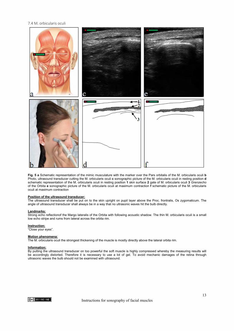
Fig. 5 a Schematic representation of the mimic musculature with the marker over the Pars orbitalis of the M. orbicularis oculi b Photo, ultrasound transducer cutting the M. orbicularis oculi c sonographic picture of the M. orbicularis oculi in resting position d schematic representation of the M. orbicularis oculi in resting position 1 skin surface 2 gate of M. orbicularis oculi 3 Grenzecho of the Orbita e sonographic picture of the M. orbicularis oculi at maximum contraction f schematic picture of the M. orbicularis oculi at maximum contraction Position of the ultrasound transducer: The ultrasound transducer shall be put on to the skin upright on pupil layer above the Proc. frontralis, Os zygomaticum. The angle of ultrasound transducer shall always be in a way that no ultrasonic waves hit the bulb directly. Landmarks: Strong echo reflectionof the Margo lateralis of the Orbita with following acoustic shadow. The thin M. orbicularis oculi is a small low echo stripe and rums from lateral across the orbita rim. Instruction: “Close your eyes”. Motion phenomena: The M. orbicularis oculi the strongest thickening of the muscle is mostly directly above the lateral orbita rim. Information: By putting the ultrasound transducer on too powerful the soft muscle is highly compressed whereby the measuring results will be accordingly distorted. Therefore it is necessary to use a lot of gel. To avoid mechanic damages of the retina through ultrasonic waves the bulb should not be examined with ultrasound.
13 Instructions for sonography of facial muscles
Interpretation of errors: By choosing the ultrasonic level the muscle can be easily identified. In extreme cases such as people with extremely high BMI or patients with chronic facial nerve paresis the identification might be more difficult. In those cases the request for contraction or slightly shifting the ultrasound transducer is helpful. The hyperechoic thresholds of the muscle can be displayed easily and clearly identified. Evaluation: This long and flat muscle cannot be encircled because it cannot be captured entirely in the scan. The values for the Areas would not match the real size of the muscle. Therefore only one square diameter is measured, which should vary between relaxation and contraction. To measure these differences one has to pick the same spot for the square distance in relaxation and in contraction.
14 Instructions for sonography of facial muscles
7.5 M. nasalis
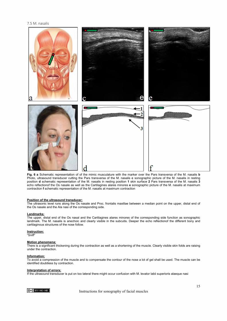
Fig. 6 a Schematic representation of of the mimic musculature with the marker over the Pars transversa of the M. nasalis b Photo, ultrasound transducer cutting the Pars transversa of the M. nasalis c sonographic picture of the M. nasalis in resting position d schematic representation of the M. nasalis in resting position 1 skin surface 2 Pars transversa of the M. nasalis 3 echo reflectionof the Os nasale as well as the Cartilagines alares minores e sonographic picture of the M. nasalis at maximum contraction f schematic representation of the M. nasalis at maximum contraction Position of the ultrasound transducer: The ultrasonic level runs along the Os nasale and Proc. frontalis maxillae between a median point on the upper, distal end of the Os nasale and the Ala nasi of the corresponding side. Landmarks: The upper, distal end of the Os nasal and the Cartilagines alares minores of the corresponding side function as sonographic landmark. The M. nasalis is anechoic and clearly visible in the subcutis. Deeper the echo reflectionof the different bony and cartilaginous structures of the nose follow. Instruction: “Sniff” Motion phenomena: There is a significant thickening during the contraction as well as a shortening of the muscle. Clearly visible skin folds are raising under the contraction. Information: To avoid a compression of the muscle and to compensate the contour of the nose a lot of gel shall be used. The muscle can be identified doubtless by contraction. Interpretation of errors: If the ultrasound transducer is put on too lateral there might occur confusion with M. levator labii superioris alaeque nasi
e
c
15 Instructions for sonography of facial muscles
7.6 Mm. mentales
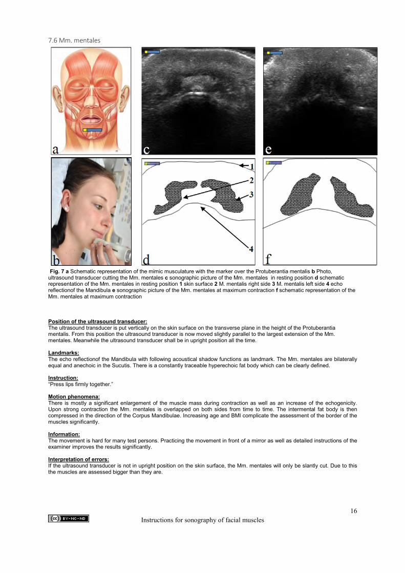
Fig. 7 a Schematic representation of the mimic musculature with the marker over the Protuberantia mentalis b Photo, ultrasound transducer cutting the Mm. mentales c sonographic picture of the Mm. mentales in resting position d schematic representation of the Mm. mentales in resting position 1 skin surface 2 M. mentalis right side 3 M. mentalis left side 4 echo reflectionof the Mandibula e sonographic picture of the Mm. mentales at maximum contraction f schematic representation of the Mm. mentales at maximum contraction Position of the ultrasound transducer: The ultrasound transducer is put vertically on the skin surface on the transverse plane in the height of the Protuberantia mentalis. From this position the ultrasound transducer is now moved slightly parallel to the largest extension of the Mm. mentales. Meanwhile the ultrasound transducer shall be in upright position all the time. Landmarks: The echo reflectionof the Mandibula with following acoustical shadow functions as landmark. The Mm. mentales are bilaterally equal and anechoic in the Sucutis. There is a constantly traceable hyperechoic fat body which can be clearly defined. Instruction: “Press lips firmly together.” Motion phenomena: There is mostly a significant enlargement of the muscle mass during contraction as well as an increase of the echogenicity. Upon strong contraction the Mm. mentales is overlapped on both sides from time to time. The intermental fat body is then compressed in the direction of the Corpus Mandibulae. Increasing age and BMI complicate the assessment of the border of the muscles significantly. Information: The movement is hard for many test persons. Practicing the movement in front of a mirror as well as detailed instructions of the examiner improves the results significantly. Interpretation of errors: If the ultrasound transducer is not in upright position on the skin surface, the Mm. mentales will only be slantly cut. Due to this the muscles are assessed bigger than they are.
16 Instructions for sonography of facial muscles
7.7 M. orbicularis oris
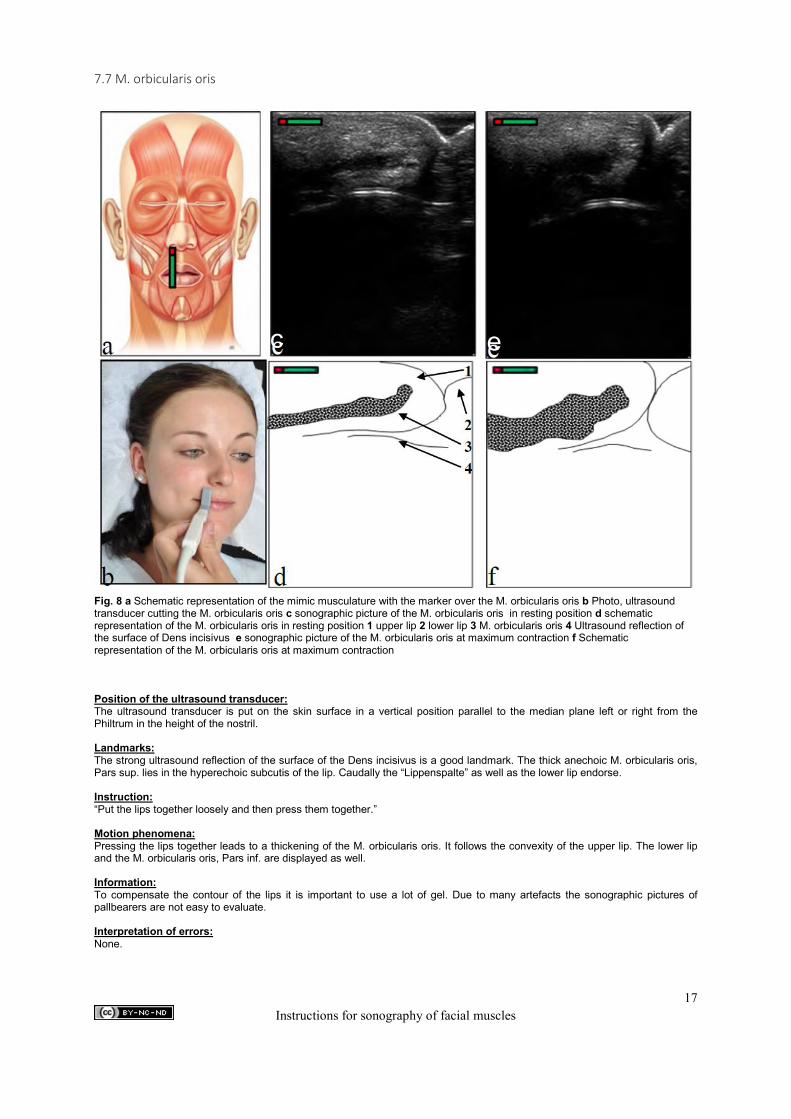
Fig. 8 a Schematic representation of the mimic musculature with the marker over the M. orbicularis oris b Photo, ultrasound transducer cutting the M. orbicularis oris c sonographic picture of the M. orbicularis oris in resting position d schematic representation of the M. orbicularis oris in resting position 1 upper lip 2 lower lip 3 M. orbicularis oris 4 Ultrasound reflection of the surface of Dens incisivus e sonographic picture of the M. orbicularis oris at maximum contraction f Schematic representation of the M. orbicularis oris at maximum contraction Position of the ultrasound transducer: The ultrasound transducer is put on the skin surface in a vertical position parallel to the median plane left or right from the Philtrum in the height of the nostril. Landmarks: The strong ultrasound reflection of the surface of the Dens incisivus is a good landmark. The thick anechoic M. orbicularis oris, Pars sup. lies in the hyperechoic subcutis of the lip. Caudally the “Lippenspalte” as well as the lower lip endorse. Instruction: “Put the lips together loosely and then press them together.” Motion phenomena: Pressing the lips together leads to a thickening of the M. orbicularis oris. It follows the convexity of the upper lip. The lower lip and the M. orbicularis oris, Pars inf. are displayed as well. Information: To compensate the contour of the lips it is important to use a lot of gel. Due to many artefacts the sonographic pictures of pallbearers are not easy to evaluate. Interpretation of errors: None.
e
c
17 Instructions for sonography of facial muscles
7.8 M. depressor anguli oris / M. depressor labii inferioris
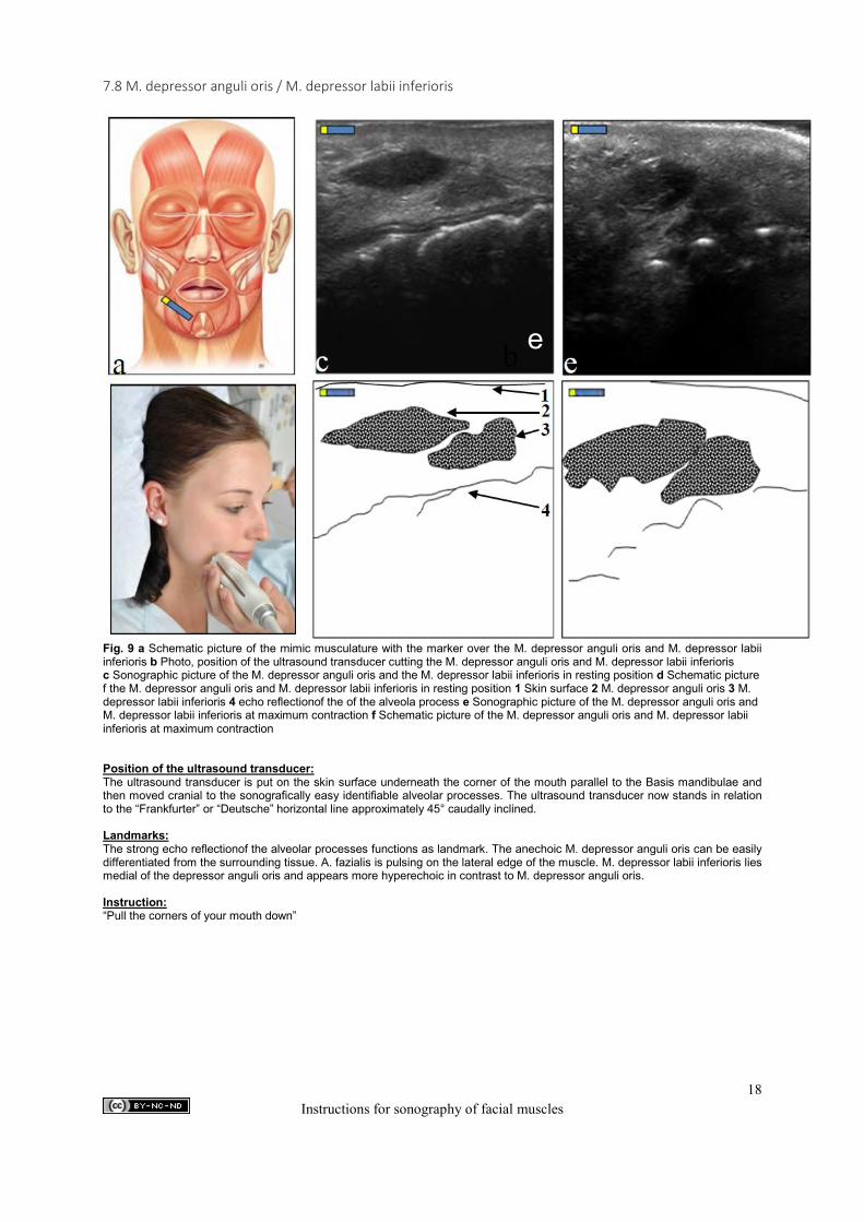
Fig. 9 a Schematic picture of the mimic musculature with the marker over the M. depressor anguli oris and M. depressor labii inferioris b Photo, position of the ultrasound transducer cutting the M. depressor anguli oris and M. depressor labii inferioris c Sonographic picture of the M. depressor anguli oris and the M. depressor labii inferioris in resting position d Schematic picture f the M. depressor anguli oris and M. depressor labii inferioris in resting position 1 Skin surface 2 M. depressor anguli oris 3 M. depressor labii inferioris 4 echo reflectionof the of the alveola process e Sonographic picture of the M. depressor anguli oris and M. depressor labii inferioris at maximum contraction f Schematic picture of the M. depressor anguli oris and M. depressor labii inferioris at maximum contraction Position of the ultrasound transducer: The ultrasound transducer is put on the skin surface underneath the corner of the mouth parallel to the Basis mandibulae and then moved cranial to the sonografically easy identifiable alveolar processes. The ultrasound transducer now stands in relation to the “Frankfurter” or “Deutsche” horizontal line approximately 45° caudally inclined. Landmarks: The strong echo reflectionof the alveolar processes functions as landmark. The anechoic M. depressor anguli oris can be easily differentiated from the surrounding tissue. A. fazialis is pulsing on the lateral edge of the muscle. M. depressor labii inferioris lies medial of the depressor anguli oris and appears more hyperechoic in contrast to M. depressor anguli oris. Instruction: “Pull the corners of your mouth down”
e
18 Instructions for sonography of facial muscles
Motion phenomena: There is a significant thickening and medial shift of both target muscles at contraction. This is particularly clear at M. depressor anguli oris. As it is hard for many people to consciously make the corresponding move this should be practiced in front of a mirror before. Information: The alveolar processes cannot be identified easily in humans with third teeth. In this case the almost diagonal echo reflectionline of the Pars alveolaris mandibulae can be used for orientation finding the right position for the ultrasound transducer. Also the A. fazialis pulsing on the lateral edge of the M. depressor anguli oris can be used for finding the target muscle. Interpretation of errors: Depending on the position of the ultrasound transducer and the angle of the ultrasonic plane to the skin surface the muscles can appear too small or too big.
19 Instructions for sonography of facial muscles
7.9 M. risorius
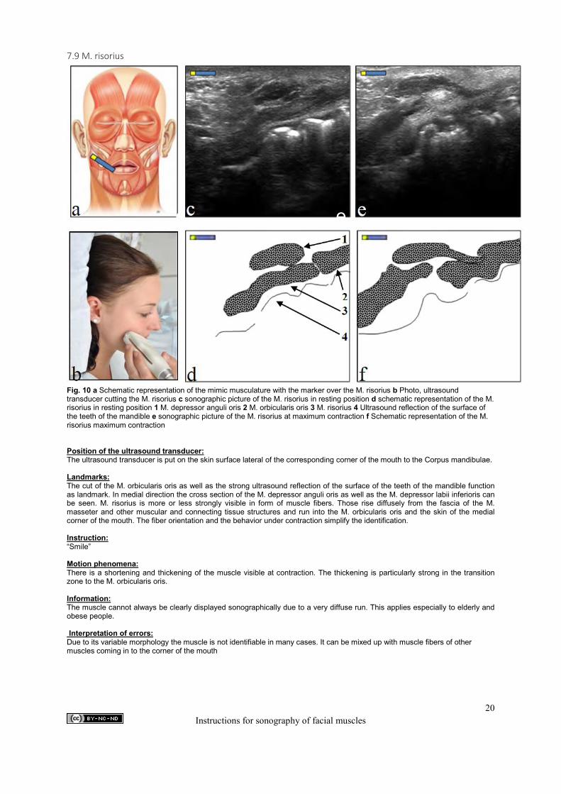
Fig. 10 a Schematic representation of the mimic musculature with the marker over the M. risorius b Photo, ultrasound transducer cutting the M. risorius c sonographic picture of the M. risorius in resting position d schematic representation of the M. risorius in resting position 1 M. depressor anguli oris 2 M. orbicularis oris 3 M. risorius 4 Ultrasound reflection of the surface of the teeth of the mandible e sonographic picture of the M. risorius at maximum contraction f Schematic representation of the M. risorius maximum contraction Position of the ultrasound transducer: The ultrasound transducer is put on the skin surface lateral of the corresponding corner of the mouth to the Corpus mandibulae. Landmarks: The cut of the M. orbicularis oris as well as the strong ultrasound reflection of the surface of the teeth of the mandible function as landmark. In medial direction the cross section of the M. depressor anguli oris as well as the M. depressor labii inferioris can be seen. M. risorius is more or less strongly visible in form of muscle fibers. Those rise diffusely from the fascia of the M. masseter and other muscular and connecting tissue structures and run into the M. orbicularis oris and the skin of the medial corner of the mouth. The fiber orientation and the behavior under contraction simplify the identification. Instruction: “Smile” Motion phenomena: There is a shortening and thickening of the muscle visible at contraction. The thickening is particularly strong in the transition zone to the M. orbicularis oris. Information: The muscle cannot always be clearly displayed sonographically due to a very diffuse run. This applies especially to elderly and obese people. Interpretation of errors: Due to its variable morphology the muscle is not identifiable in many cases. It can be mixed up with muscle fibers of other muscles coming in to the corner of the mouth
e
c
20 Instructions for sonography of facial muscles
7.10 M. zygomaticus major
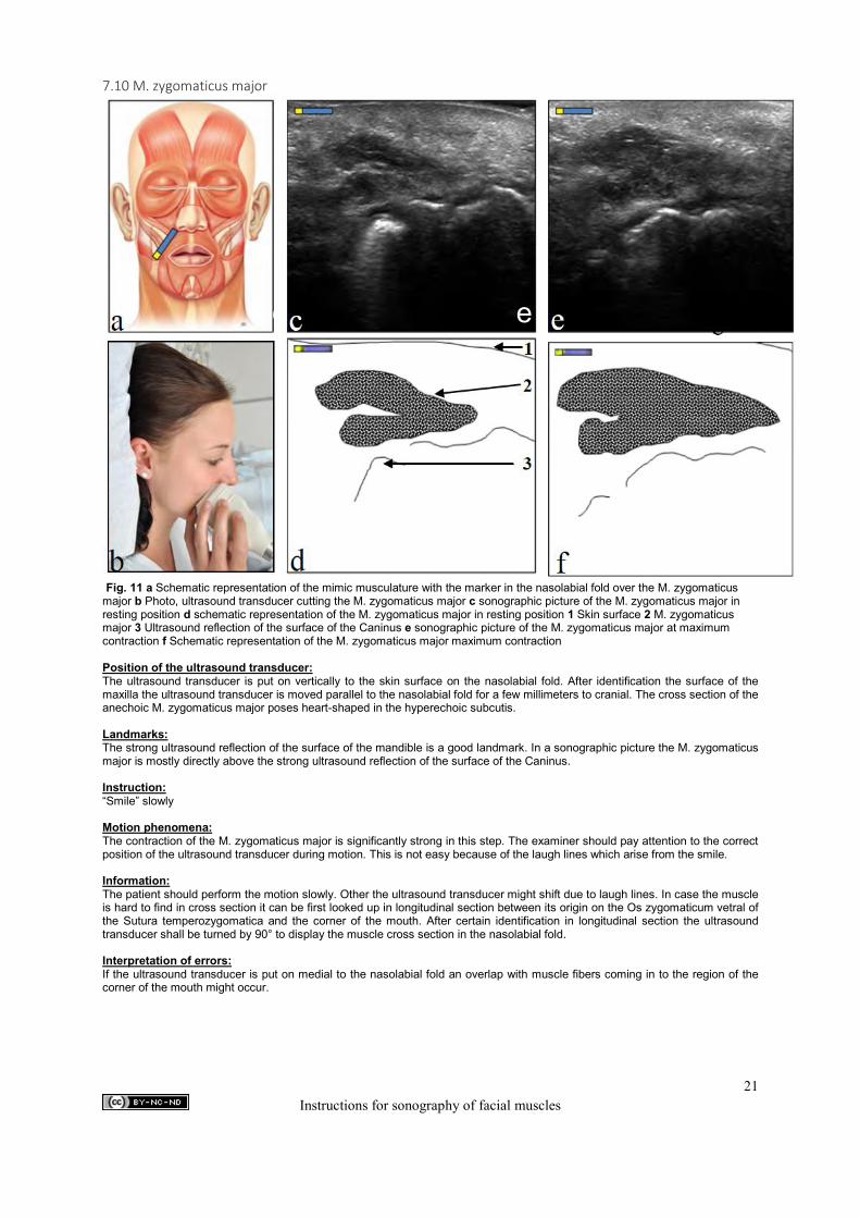
Fig. 11 a Schematic representation of the mimic musculature with the marker in the nasolabial fold over the M. zygomaticus major b Photo, ultrasound transducer cutting the M. zygomaticus major c sonographic picture of the M. zygomaticus major in resting position d schematic representation of the M. zygomaticus major in resting position 1 Skin surface 2 M. zygomaticus major 3 Ultrasound reflection of the surface of the Caninus e sonographic picture of the M. zygomaticus major at maximum contraction f Schematic representation of the M. zygomaticus major maximum contraction Position of the ultrasound transducer: The ultrasound transducer is put on vertically to the skin surface on the nasolabial fold. After identification the surface of the maxilla the ultrasound transducer is moved parallel to the nasolabial fold for a few millimeters to cranial. The cross section of the anechoic M. zygomaticus major poses heart-shaped in the hyperechoic subcutis. Landmarks: The strong ultrasound reflection of the surface of the mandible is a good landmark. In a sonographic picture the M. zygomaticus major is mostly directly above the strong ultrasound reflection of the surface of the Caninus. Instruction: “Smile” slowly Motion phenomena: The contraction of the M. zygomaticus major is significantly strong in this step. The examiner should pay attention to the correct position of the ultrasound transducer during motion. This is not easy because of the laugh lines which arise from the smile. Information: The patient should perform the motion slowly. Other the ultrasound transducer might shift due to laugh lines. In case the muscle is hard to find in cross section it can be first looked up in longitudinal section between its origin on the Os zygomaticum vetral of the Sutura temperozygomatica and the corner of the mouth. After certain identification in longitudinal section the ultrasound transducer shall be turned by 90° to display the muscle cross section in the nasolabial fold. Interpretation of errors: If the ultrasound transducer is put on medial to the nasolabial fold an overlap with muscle fibers coming in to the region of the corner of the mouth might occur.
e
c
21 Instructions for sonography of facial muscles
7.11 M. zygomaticus minor
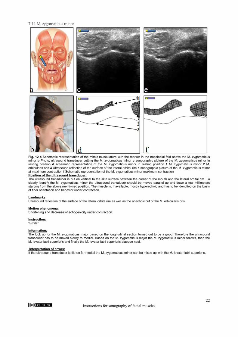
Fig. 12 a Schematic representation of the mimic musculature with the marker in the nasolabial fold above the M. zygomaticus minor b Photo, ultrasound transducer cutting the M. zygomaticus minor c sonographic picture of the M. zygomaticus minor in resting position d schematic representation of the M. zygomaticus minor in resting position 1 M. zygomaticus minor 2 M. orbicularis oris 3 Ultrasound reflection of the surface of the lateral orbital rim e sonographic picture of the M. zygomaticus minor at maximum contraction f Schematic representation of the M. zygomaticus minor maximum contraction Position of the ultrasound transducer: The ultrasound transducer is put on vertical to the skin surface between the corner of the mouth and the lateral orbital rim. To clearly identify the M. zygomaticus minor the ultrasound transducer should be moved parallel up and down a few millimeters starting from the above mentioned position. The muscle is, if available, mostly hyperechoic and has to be identified on the basis of fiber orientation and behavior under contraction. Landmarks: Ultrasound reflection of the surface of the lateral orbita rim as well as the anechoic cut of the M. orbicularis oris. Motion phenomena: Shortening and decrease of echogenicity under contraction. Instruction: “Smile” Information: The look up for the M. zygomaticus major based on the longitudinal section turned out to be a good. Therefore the ultrasound transducer has to be moved slowly to medial. Based on the M. zygomaticus major the M. zygomaticus minor follows, then the M. levator labii superioris and finally the M. levator labii superioris alaeque nasi. Interpretation of errors: If the ultrasound transducer is tilt too far medial the M. zygomaticus minor can be mixed up with the M. levator labii superioris.
1
22 Instructions for sonography of facial muscles
7.12 M. levator labii superioris
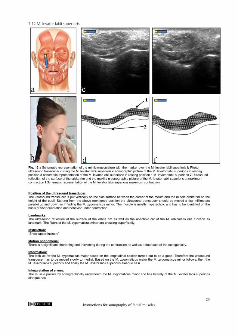
Fig. 13 a Schematic representation of the mimic musculature with the marker over the M. levator labii superioris b Photo, ultrasound transducer cutting the M. levator labii superioris c sonographic picture of the M. levator labii superioris in resting position d schematic representation of the M. levator labii superioris in resting position 1 M. levator labii superioris 2 Ultrasound reflection of the surface of the orbita rim and the maxilla e sonographic picture of the M. levator labii superioris at maximum contraction f Schematic representation of the M. levator labii superioris maximum contraction Position of the ultrasound transducer: The ultrasound transducer is put vertically on the skin surface between the corner of the mouth and the middle orbita rim on the height of the pupil. Starting from the above mentioned position the ultrasound transducer should be moved a few millimeters parallel up and down as if finding the M. zygomaticus minor. The muscle is mostly hyperechoic and has to be identified on the basis of fiber orientation and behavior under contraction. Landmarks: The ultrasound reflection of the surface of the orbita rim as well as the anechoic cut of the M. orbicularis oris function as landmark. The fibers of the M. zygomaticus minor are crossing superficially. Instruction: “Show upper incisors” Motion phenomena: There is a significant shortening and thickening during the contraction as well as a decrease of the echogenicity. Information: The look up for the M. zygomaticus major based on the longitudinal section turned out to be a good. Therefore the ultrasound transducer has to be moved slowly to medial. Based on the M. zygomaticus major the M. zygomaticus minor follows, then the M. levator labii superioris and finally the M. levator labii superioris alaeque nasi. Interpretation of errors: The muscle passes by sonographically underneath the M. zygomaticus minor and lies lateraly of the M. levator labii superioris alaeque nasi.
c
e
23 Instructions for sonography of facial muscles
7.13 M. levator labii superioris alaeque nasi
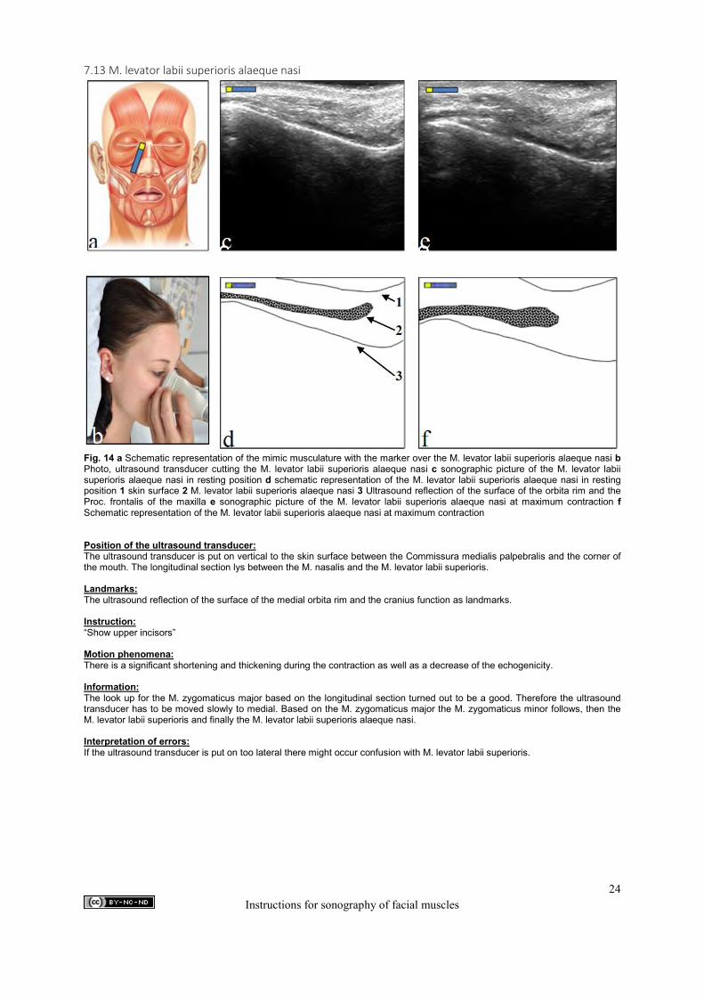
Fig. 14 a Schematic representation of the mimic musculature with the marker over the M. levator labii superioris alaeque nasi b Photo, ultrasound transducer cutting the M. levator labii superioris alaeque nasi c sonographic picture of the M. levator labii superioris alaeque nasi in resting position d schematic representation of the M. levator labii superioris alaeque nasi in resting position 1 skin surface 2 M. levator labii superioris alaeque nasi 3 Ultrasound reflection of the surface of the orbita rim and the Proc. frontalis of the maxilla e sonographic picture of the M. levator labii superioris alaeque nasi at maximum contraction f Schematic representation of the M. levator labii superioris alaeque nasi at maximum contraction Position of the ultrasound transducer: The ultrasound transducer is put on vertical to the skin surface between the Commissura medialis palpebralis and the corner of the mouth. The longitudinal section lys between the M. nasalis and the M. levator labii superioris. Landmarks: The ultrasound reflection of the surface of the medial orbita rim and the cranius function as landmarks. Instruction: “Show upper incisors” Motion phenomena: There is a significant shortening and thickening during the contraction as well as a decrease of the echogenicity. Information: The look up for the M. zygomaticus major based on the longitudinal section turned out to be a good. Therefore the ultrasound transducer has to be moved slowly to medial. Based on the M. zygomaticus major the M. zygomaticus minor follows, then the M. levator labii superioris and finally the M. levator labii superioris alaeque nasi. Interpretation of errors: If the ultrasound transducer is put on too lateral there might occur confusion with M. levator labii superioris.
e
c
24 Instructions for sonography of facial muscles
7.14 M. buccinator
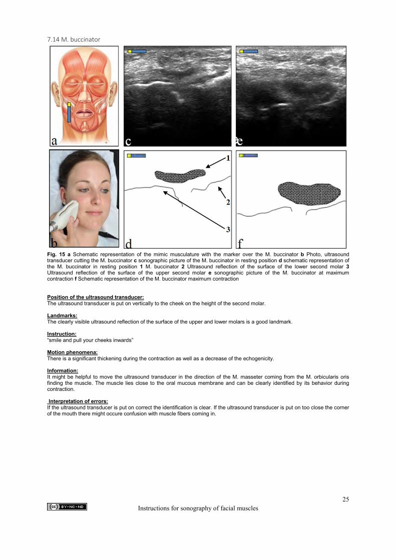
Fig. 15 a Schematic representation of the mimic musculature with the marker over the M. buccinator b Photo, ultrasound transducer cutting the M. buccinator c sonographic picture of the M. buccinator in resting position d schematic representation of the M. buccinator in resting position 1 M. buccinator 2 Ultrasound reflection of the surface of the lower second molar 3 Ultrasound reflection of the surface of the upper second molar e sonographic picture of the M. buccinator at maximum contraction f Schematic representation of the M. buccinator maximum contraction Position of the ultrasound transducer: The ultrasound transducer is put on vertically to the cheek on the height of the second molar. Landmarks: The clearly visible ultrasound reflection of the surface of the upper and lower molars is a good landmark. Instruction: “smile and pull your cheeks inwards” Motion phenomena: There is a significant thickening during the contraction as well as a decrease of the echogenicity. Information: It might be helpful to move the ultrasound transducer in the direction of the M. masseter coming from the M. orbicularis oris finding the muscle. The muscle lies close to the oral mucous membrane and can be clearly identified by its behavior during contraction. Interpretation of errors: If the ultrasound transducer is put on correct the identification is clear. If the ultrasound transducer is put on too close the corner of the mouth there might occure confusion with muscle fibers coming in.
e
25 Instructions for sonography of facial muscles
8. Sonographic cut of the chewing muscles 8.1 M. temporalis
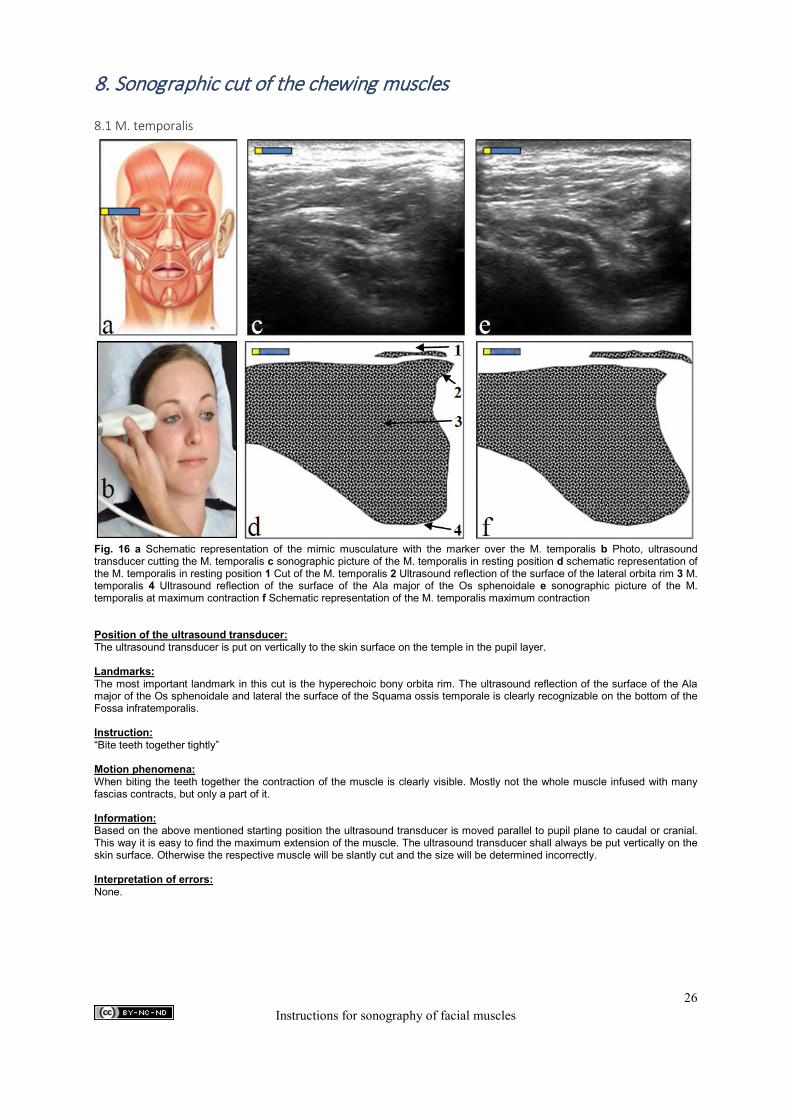
Fig. 16 a Schematic representation of the mimic musculature with the marker over the M. temporalis b Photo, ultrasound transducer cutting the M. temporalis c sonographic picture of the M. temporalis in resting position d schematic representation of the M. temporalis in resting position 1 Cut of the M. temporalis 2 Ultrasound reflection of the surface of the lateral orbita rim 3 M. temporalis 4 Ultrasound reflection of the surface of the Ala major of the Os sphenoidale e sonographic picture of the M. temporalis at maximum contraction f Schematic representation of the M. temporalis maximum contraction Position of the ultrasound transducer: The ultrasound transducer is put on vertically to the skin surface on the temple in the pupil layer. Landmarks: The most important landmark in this cut is the hyperechoic bony orbita rim. The ultrasound reflection of the surface of the Ala major of the Os sphenoidale and lateral the surface of the Squama ossis temporale is clearly recognizable on the bottom of the Fossa infratemporalis. Instruction: “Bite teeth together tightly” Motion phenomena: When biting the teeth together the contraction of the muscle is clearly visible. Mostly not the whole muscle infused with many fascias contracts, but only a part of it. Information: Based on the above mentioned starting position the ultrasound transducer is moved parallel to pupil plane to caudal or cranial. This way it is easy to find the maximum extension of the muscle. The ultrasound transducer shall always be put vertically on the skin surface. Otherwise the respective muscle will be slantly cut and the size will be determined incorrectly. Interpretation of errors: None.
26 Instructions for sonography of facial muscles
8.2 M. masseter
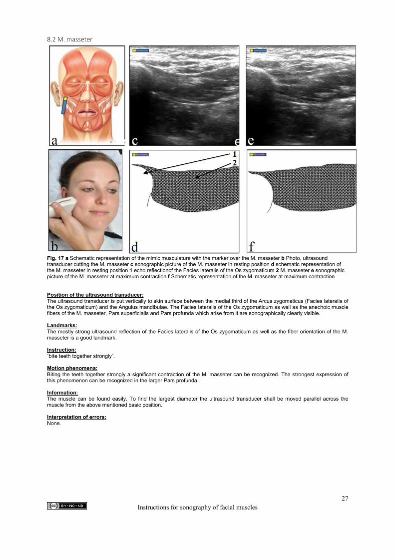
Fig. 17 a Schematic representation of the mimic musculature with the marker over the M. masseter b Photo, ultrasound transducer cutting the M. masseter c sonographic picture of the M. masseter in resting position d schematic representation of the M. masseter in resting position 1 echo reflectionof the Facies lateralis of the Os zygomaticum 2 M. masseter e sonographic picture of the M. masseter at maximum contraction f Schematic representation of the M. masseter at maximum contraction Position of the ultrasound transducer: The ultrasound transducer is put vertically to skin surface between the medial third of the Arcus zygomaticus (Facies lateralis of the Os zygomaticum) and the Angulus mandibulae. The Facies lateralis of the Os zygomaticum as well as the anechoic muscle fibers of the M. masseter, Pars superficialis and Pars profunda which arise from it are sonographically clearly visible. Landmarks: The mostly strong ultrasound reflection of the Facies lateralis of the Os zygomaticum as well as the fiber orientation of the M. masseter is a good landmark. Instruction: “bite teeth together strongly”. Motion phenomena: Biting the teeth together strongly a significant contraction of the M. masseter can be recognized. The strongest expression of this phenomenon can be recognized in the larger Pars profunda. Information: The muscle can be found easily. To find the largest diameter the ultrasound transducer shall be moved parallel across the muscle from the above mentioned basic position. Interpretation of errors: None.
e
c
27 Instructions for sonography of facial muscles
9. Power Doppler - Sonography of the facial arteries 9.1 A. facialis
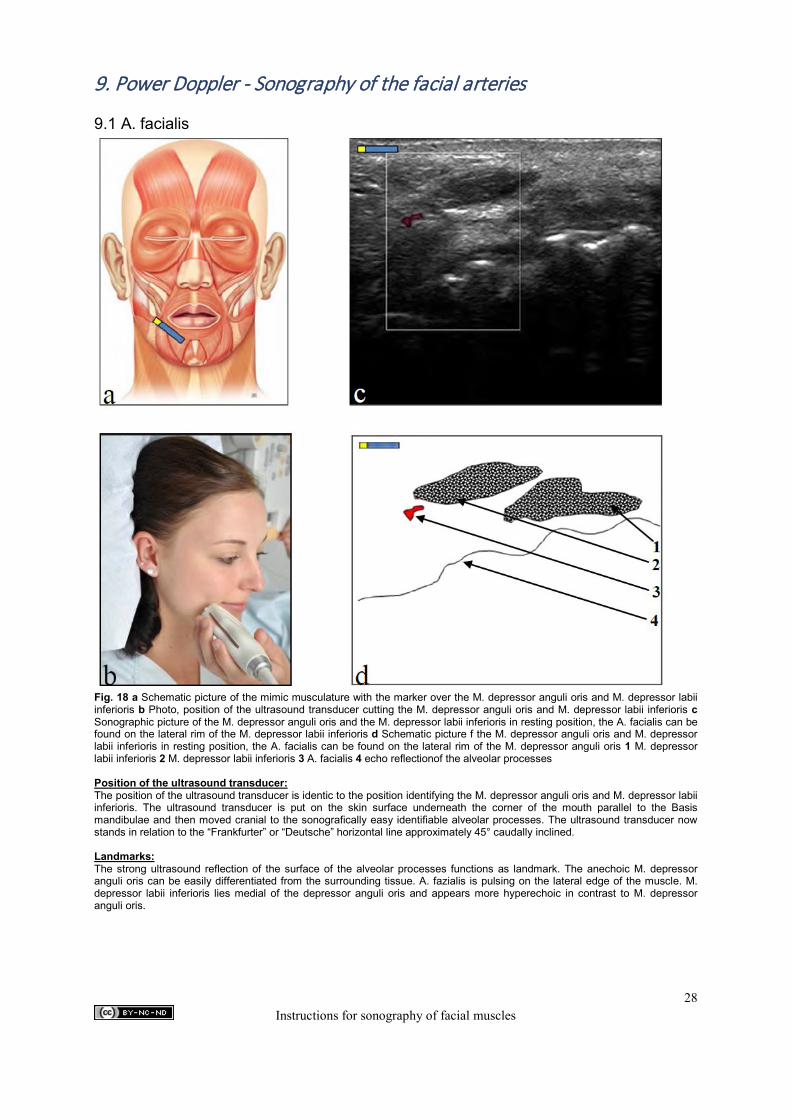
Fig. 18 a Schematic picture of the mimic musculature with the marker over the M. depressor anguli oris and M. depressor labii inferioris b Photo, position of the ultrasound transducer cutting the M. depressor anguli oris and M. depressor labii inferioris c Sonographic picture of the M. depressor anguli oris and the M. depressor labii inferioris in resting position, the A. facialis can be found on the lateral rim of the M. depressor labii inferioris d Schematic picture f the M. depressor anguli oris and M. depressor labii inferioris in resting position, the A. facialis can be found on the lateral rim of the M. depressor anguli oris 1 M. depressor labii inferioris 2 M. depressor labii inferioris 3 A. facialis 4 echo reflectionof the alveolar processes Position of the ultrasound transducer: The position of the ultrasound transducer is identic to the position identifying the M. depressor anguli oris and M. depressor labii inferioris. The ultrasound transducer is put on the skin surface underneath the corner of the mouth parallel to the Basis mandibulae and then moved cranial to the sonografically easy identifiable alveolar processes. The ultrasound transducer now stands in relation to the “Frankfurter” or “Deutsche” horizontal line approximately 45° caudally inclined. Landmarks: The strong ultrasound reflection of the surface of the alveolar processes functions as landmark. The anechoic M. depressor anguli oris can be easily differentiated from the surrounding tissue. A. fazialis is pulsing on the lateral edge of the muscle. M. depressor labii inferioris lies medial of the depressor anguli oris and appears more hyperechoic in contrast to M. depressor anguli oris.
28 Instructions for sonography of facial muscles
Information: After identifying the correct ultrasound transducer position the A. facialis can be easily found on the edge of the M. depressor anguli oris. The ultrasound transducer shall always be put on softly to avoid compression of the vessels. Sometimes the A. fazialis splits up in many little branches. If this is the case the ultrasound transducer shall be moved to caudal based on the above described position. A main branch will mostly be found then. Interpretation of errors: Depending on the position of the ultrasound transducer and the angle of the ultrasonic plane to the skin surface the artery can be cut diagonal. By slightly swiveling the ultrasound transducer a straight cut of the vessel can be performed.
29 Instructions for sonography of facial muscles
9.2 A. temporalis profunda anterior
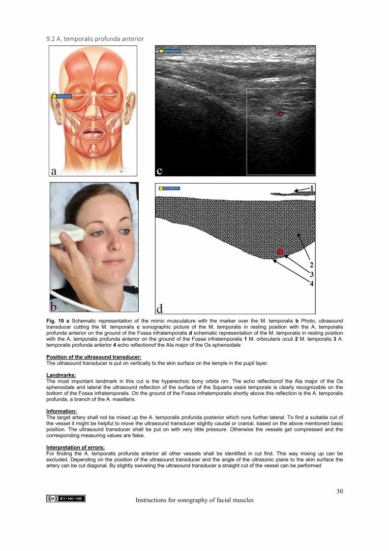
Fig. 19 a Schematic representation of the mimic musculature with the marker over the M. temporalis b Photo, ultrasound transducer cutting the M. temporalis c sonographic picture of the M. temporalis in resting position with the A. temporalis profunda anterior on the ground of the Fossa infratemporalis d schematic representation of the M. temporalis in resting position with the A. temporalis profunda anterior on the ground of the Fossa infratemporalis 1 M. orbicularis oculi 2 M. temporalis 3 A. temporalis profunda anterior 4 echo reflectionof the Ala major of the Os sphenoidale Position of the ultrasound transducer: The ultrasound transducer is put on vertically to the skin surface on the temple in the pupil layer.
Landmarks: The most important landmark in this cut is the hyperechoic bony orbita rim. The echo reflectionof the Ala major of the Os sphenoidale and lateral the ultrasound reflection of the surface of the Squama ossis temporale is clearly recognizable on the bottom of the Fossa infratemporalis. On the ground of the Fossa infratemporalis shortly above this reflection is the A. temporalis profunda, a branch of the A. maxillaris. Information: The target artery shall not be mixed up the A. temporalis profunda posterior which runs further lateral. To find a suitable cut of the vessel it might be helpful to move the ultrasound transducer slightly caudal or cranial, based on the above mentioned basic position. The ultrasound transducer shall be put on with very little pressure. Otherwise the vessels get compressed and the corresponding measuring values are false. Interpretation of errors: For finding the A. temporalis profunda anterior all other vessels shall be identified in cut first. This way mixing up can be excluded. Depending on the position of the ultrasound transducer and the angle of the ultrasonic plane to the skin surface the artery can be cut diagonal. By slightly swiveling the ultrasound transducer a straight cut of the vessel can be performed
c
30 Instructions for sonography of facial muscles

9.3 A. labialis superior
Fig. 20 a Schematic representation of the mimic musculature with the marker over the M. orbicularis oris b Photo, ultrasound transducer cutting the M. orbicularis oris c sonographic picture of the M. orbicularis oris in resting position with A. labialis superior d schematic representation of the M. orbicularis oris in resting position with A. labialis superior 2 lower lip 3 upper lip 4 M. orbicularis oris 5 Ultrasound reflection of the surface of the Dens incisivus Position of the ultrasound transducer: The ultrasound transducer is put on the skin surface vertical position parallel to the median plane left or right from the Philtrum in the height of the nostril. Landmarks: The strong ultrasound reflection of the surface of the Dens incisivus is a good landmark. The thick anechoic M. orbicularis oris, Pars sup. lies in the hyperechoic subcutis of the lip. Caudally the “Lippenspalte” as well as the lower lip endorse. Information: The A. labialis superior mostly shows a wriggled course through the upper lip. To get a straight cut of the vessel it can be helpful to move the ultrasound transducer a few millimeters left or right. Due to many artefacts the measuring values of pallbearers are unusable. Interpretation of errors: None.
31 Instructions for sonography of facial muscles