
INSTRUCTION BOOK - All Pumps Direct 1B USER MA… · INSTRUCTION BOOK 43380207-ENG-10.05-3 Printed...
37
INSTRUCTION BOOK 433 802 07 - ENG - 10.05 - 3 Printed in Germany 33 1B 20 1B 27 1B 30 1B 40 1B 50
Transcript of INSTRUCTION BOOK - All Pumps Direct 1B USER MA… · INSTRUCTION BOOK 43380207-ENG-10.05-3 Printed...
INSTRUCTION BOOK
433 80207 -ENG -10.05 -3Printed in Germany
33
1B201B271B301B401B50
A new HATZ Diesel engine - working for you
This engine is intended only for the purpose determined and tested by the manufacturer of the equipment in which it is installed. Using it in any other manner contravenes the intended purpose.For danger and damage due to this, Motorenfabrik HATZ assumes no liability. The risk is with the user only. Use of this engine in the intended manner presupposes compliance with the maintenance and repairinstructions laid down for it. Noncompliance leads to engine breakdown.
Please do not fail to read this operating manual before starting the engine. This will help you to avoidaccidents, ensure that you operate the engine correctly and assist you in complying with the mainte-nance intervals in order to ensure long-lasting, reliable performance.
Please pass this Instruction Manual on to the next user or to the following engine owner.
The worldwide HATZ Service Network is at your disposal to advise you, supply with spare parts andundertake servicing work.You will find the address of your nearest HATZ service station in the enclosed list.
Use only original spare parts from HATZ. Only these parts guarantee a perfect dimensional stabilityand quality. The order numbers can be found in the enclosed spare parts list. Please note the sparepart kits shown in Table M00.
We reserve the right to make modifications in the course of technical progress.
MOTORENFABRIK HATZ GMBH & CO KG
1

Page
1. Important safety notes when operating the engine 3
2. Description of the engine 5
3. General notes 63.1. Technical data 63.2. Transport 73.3 Notes on installation 73.4. Load on engine 73.5. Type plate 7
4. Operation 84.1. Prior to first-time start-up 84.1.1. Engine oil 84.1.2. Version with oilbath air cleaner 94.1.3. Fuel 94.2. Starting 104.2.1. Preparations for starting 104.2.2. Recoil starter 124.2.3. Electric starter 134.3. Stopping the engine 15
5. Maintenance 175.1. Maintenance chart 17
5.2. Maintenance every 8–15operating hours 19
5.2.1. Checking engine oil level 195.2.2. Check air intake area for
combustion and cooling 195.2.3. Check air cleaner maintenance
indicator 205.2.4. Checking the water trap 20
Page
5.3. Maintenance every 250operating hours 21
5.3.1. Oilbath air cleaner maintenance 215.3.2. Changing engine oil 225.3.3. Checking and adjusting
valve clearances 235.3.4. Cleaning cooling air area 245.3.5. Checking screw connections 245.3.6. Cleaning the exhaust mesh inlet 25
5.4. Maintenance every 500operating hours 26
5.4.1. Renewing fuel filter 265.4.2. Air cleaner maintenance 27
5.5. Maintenance every 1000operating hours 29
5.5.1. Cleaning the oil filter 29
6. Malfunctions–causes– remedies 31
7. Work on the electrical system 35
8. Storage out of use 35
2
Contents
This symbol identifies important safety precautions.Please comply with these most carefully in order to avoid any risk of injury to persons ordamage to materials.General legal requirements and safety regulations issued by the competent authorities orindustrial accident insurers must also be complied with.

1. Important safety notes when operating the engine
HATZ diesel engines are efficient, strong and durable. For this reason they are frequently installed onequipment used for commercial purposes.The manufacturers of such equipment must observe any relevant equipment safety regulations whenthe engine forms part of an overall system.A few general points concerning operating safety should none the less be noted.Depending on the engine’s operating and installation conditions, equipment manufacturers and theirusers may have to fit safety or protective devices in order to prevent improper use. Examples:
– Exhaust system components as well as the surface of the engine will naturally be hot and must notbe touched while the engine is running or until it has cooled down after being stopped.
– Incorrect wiring or improper operation of the electrical system may cause sparking and must there-fore be avoided.
– Provide protection against contact with rotating parts once the engine is connected to the drivenequipment or machine.HATZ protective guards are available for the belt drive of the cooling fan and alternator drive sys-tems.
– Always observe the start-up information in the operating instructions before starting the engine:this is particularly important when starting an engine with the recoil starter.
– Mechanical starting devices should not be operated by children or persons deficient in physicalstrength.
– Check that all safety devices are in place before starting the engine.
– Ensure that operation, maintenance and repair of the engine are undertaken by suitably trained per-sonnel only.
– Protect the starter key against unauthorised use.
– Do not run the engine in closed or badly ventilated rooms.Do not breath in emissions – danger of poisoning !
– Also fuel and lubricants could contain poisonous components. Please follow the instructions of themineral oil producer.
3
Important safety notes when operating the engine
– The engine must be stopped before performing any maintenance, cleaning- or repair work.
– Stop the engine before refilling the fuel tank. Never refuel near a naked flame or sparks which could start a fire. Don’t smoke. Don’t spill fuel.
– Keep explosive materials as well as flammable materials away from the engine because the exhaustgets very hot during operation.
– Wear close-fitting clothing when working on the engine while it is running. Please don’t wear necklaces, bracelets or any other things which you could get caught with.
– Please pay attention to all advice- and warning stickers placed on the engine and keep them in legi-ble condition. Contact your next HATZ service station, if a sticker comes off or is illegible and askfor a new one.
– We accept no liability for damage resulting from improper modifications to the engine.
Regular maintenance in accordance with the details given in these operating instructions is essentialto keep the engine in good working order.
When in doubt, consult your local HATZ service station before starting the engine.
4
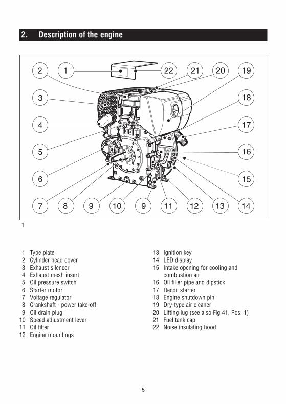
2. Description of the engine
5
2
8 9 10 9 11 12 13 14
15
16
17
18
192021
3
4
6
5
7
1 22
1
1 Type plate2 Cylinder head cover3 Exhaust silencer4 Exhaust mesh insert5 Oil pressure switch6 Starter motor7 Voltage regulator8 Crankshaft - power take-off9 Oil drain plug
10 Speed adjustment lever11 Oil filter12 Engine mountings
13 Ignition key14 LED display15 Intake opening for cooling and
combustion air16 Oil filler pipe and dipstick17 Recoil starter18 Engine shutdown pin19 Dry-type air cleaner20 Lifting lug (see also Fig 41, Pos. 1)21 Fuel tank cap22 Noise insulating hood
3. General notes
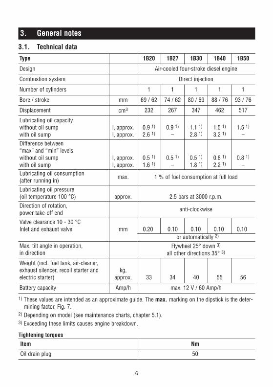
3.1. Technical data
1) These values are intended as an approximate guide. The max. marking on the dipstick is the deter-mining factor, Fig. 7.
2) Depending on model (see maintenance charts, chapter 5.1).3) Exceeding these limits causes engine breakdown.
Tightening torquesItem Nm
Oil drain plug 50
6
Type 1B20 1B27 1B30 1B40 1B50
Design Air-cooled four-stroke diesel engine
Combustion system Direct injection
Number of cylinders 1 1 1 1 1
Bore / stroke mm 69 / 62 74 / 62 80 / 69 88 / 76 93 / 76
Displacement cm3 232 267 347 462 517
Lubricating oil capacity without oil sumpwith oil sump
l, approx.l, approx.
0.9 1)
2.6 1)0.9 1)
–1.1 1)
2.8 1)1.5 1)
3.2 1)1.5 1)
–Difference between “max” and “min” levelswithout oil sumpwith oil sump
l, approx.l, approx.
0.5 1)
1.6 1)0.5 1)
–0.5 1)
1.8 1)0.8 1)
2.2 1)0.8 1)
–Lubricating oil consumption(after running in) max. 1 % of fuel consumption at full load
Lubricating oil pressure(oil temperature 100 °C) approx. 2.5 bars at 3000 r.p.m.Direction of rotation, power take-off end anti-clockwise
Valve clearance 10 - 30 °CInlet and exhaust valve mm 0.20 0.10 0.10 0.10 0.10
or automatically 2)
Max. tilt angle in operation,in direction
Flywheel 25° down 3)
all other directions 35° 3)
Weight (incl. fuel tank, air-cleaner, exhaust silencer, recoil starter andelectric starter)
kg,approx. 33 34 40 55 56
Battery capacity Amp/h max. 12 V / 60 Amp/h

3.2. Transport
Standard lifting lug „20“ is to allow the engine and its auxiliaries to be
transported safely, chap. 2. It is not suitable orapproved for lifting the complete equipment towhich the engine is attached.
3.3. Notes on installation
The „Guide to selecting and installing an engine“contains all the necessary information on engineapplications if you have an engine which has notyet been installed in equipment and still has tobe fitted or set up. This guide is available fromyour local HATZ service station.
2
Do not exceed the forces and torquesindicated on the speed adjustment
lever and the stop pin, otherwise you maydamage the stops and internal governor com-ponents.
3.4. Load on engine
Operating the engine for a lengthy period off-load or at very low loads can affect its runningquality. We therefore recommend a minimumengine load of 15 %. If operated at such lowloads, it is best to operate the engine at a signifi-cantly higher load for a short period beforeswitching it off.
F < 15 N STOP
76.5°
STOP START
F 30 N
M 2.3 Nm
<
<
3.5. Type plate
3
The type plate is placed on the noise insulatinghood (Fig. 1, pos. 1) and includes the followingengine information:➀ engine type➁ code (only for special equipment)➂ engine number (also stamped on crankcase,
Fig. 4)➃ max. engine speedFor any offer as well as spare parts orders it isnecessary to mention these data (also see spareparts list, page 1).
4
Engine serial number on crankcase
MOTORENFABRIK HATZ KGD-94099 RUHSTORF
GMBHCO+
GMBHCO+
TYP KENNZ.
MOTOR/FABRIK NO. ABE/AUSF.
MIN NH PV CM
MADE IN GERMANY
-1 3
7

4. Operation
4.1. Before starting up for the first time
Engines are normally supplied dry, i.e. not con-taining fuel or oil.
4.1.1. Engine oil
Oil qualityQualified are all trademark oils which fulfil atleast one of the following specifications:
ACEA – B2 / E2 or more significantAPI – CD / CE / CF / CF-4 / CG-4 or more significant.
If engine oil of a poorer quality is used, reduceoil change intervals to 150 hours of operation.
Oil viscosity
5
Select the viscosity class according to the ambient temperature for cold starts.
-40
-30
-20
-10
0
10
20
30
40
50
104
86
68
50
32
14
-4
-22
-40
OIL: SAE...°C°F
5W
/30
5W
/40
10W
/40
10W
/30
15W
/40
30 4
0
122
10W
When adding oil or checking the oil level, the engine must be horizontal.
6
– Remove oil filler screw and add engine oil.Lubricating oil capacity: see Chapter 3.1.
7
– To check the oil level, remove the dipstick,clean it - then screw it back in and finally remove it again.Check the oil level on the dipstick and, if necessary, top up to the max. level.
max.
8

4.1.2. Version with oilbath air cleaner
8
9
– Take off oil reservoir „1“ and fill with engine oilas far as the mark, Figs. 8 and 9.
– Insert the filter element into the oil reservoirwith the long end „2“ leading, Fig. 8.
– Attach the oil reservoir, making sure that sealing ring „3“ is correctly seated and fasteners „4“ are tight.
2444 / 5
2440 / 10
4.1.3. Fuel
Stop the engine before refilling the fuel tank. Never refuel near a naked
flame or sparks which could start a fire. Don’tsmoke. Use only pure fuel and clean fillingequipment. Take care not to spill fuel.
All diesel fuels which satisfy the following speci-fications are suitable:
EN 590 orBS 2869 A1 / A2 orASTM D 975 - 1D / 2D
10
– Remove fuel tank cap.
2439 / 12
9

11
– Before the first start or if the fuel tank hasbeen run dry, completely fill the fuel tank withdiesel. The bleeding of the fuel system is auto-matically.
Note:If a double fuel filter system is provided(Chapter 5.4.1), wait for a short time after re-plenishing fuel (approx. 1 to 2 minutes) forautomatic bleeding to be completed.
12
– Close and fix fuel tank cap.
2439 / 16
At temperatures below 0 °C, winter-grade fuelshould be used or paraffin added to the fuel wellin advance.
4.2. Starting
Do not run the engine in closed orbadly ventilated rooms – danger of
poisoning ! Before starting the engine, ensurethat no-one is in the danger area close to theengine or equipment, and that all protectiveguards are fitted.
4.2.1. Preparations for starting
If possible, disengage the engine from any driven equipment.The auxiliary equipment should always be placedin neutral.
– First of all set the speed adjuster to the STOPposition, Figures 13 and 14, then move it tothe starting position.
Lowest ambienttemperature when
starting, in °C
Paraffin content for:Summer
fuelWinter
fuel0 up to –10
–10 up to –15–15 up to –20–20 up to –30
20 %30 %50 %
–
––
20 %50 %
10

Speed adjuster, standard version
13
– Set speed adjustment lever „1“ either to 1/2START or max. START position, as desired ornecessary.Starting at a lower speed will help to preventexhaust smoke.
Speed adjuster with pull rod
14
– Move speed adjuster to the „START/RUN“position.
Now, the engine is ready for starting.
15
Never use starting sprays !
Important !After long-time standstill (approx. 6 months oreven longer) or first operation, operate enginewith low adjusted speed and without load for approx. 20 sec. after start. This measure assuresa lubrication of all bearings before increasingspeed and load.It also prevents an insufficient lubrication.
050 145 00
11

4.2.2. Recoil starter (down to –6 °C)
– For starting preparations, see Chapter 4.2.1.
Starting procedure
16
– Pull the starting cable out by the handle untilyou feel a slight resistance.
– Let the cable run back; in this way the entirelength of the starting cable can be used tostart the engine.
– Devices which are not securely fastenedshould be restrained with the foot.
17
– Grip the handle with both hands.
18
– Commence pulling the starting cable vigorous-ly and at an increasing speed (do not jerk it violently) until the engine starts
Note:If after several attempts of starting the exhaustbegins to emit white smoke, move the speed ad-justment lever to the STOP position and pull thestarting cable out slowly 5 times. Repeat the starting procedure, Chapter 4.2.1.
12
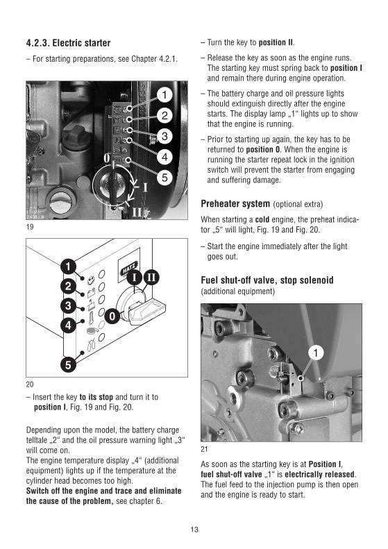
4.2.3. Electric starter
– For starting preparations, see Chapter 4.2.1.
19
20
– Insert the key to its stop and turn it to position I, Fig. 19 and Fig. 20.
Depending upon the model, the battery chargetelltale „2“ and the oil pressure warning light „3“will come on. The engine temperature display „4“ (additionalequipment) lights up if the temperature at thecylinder head becomes too high.Switch off the engine and trace and eliminatethe cause of the problem, see chapter 6.
�
�
�
�
�
– Turn the key to position II.
– Release the key as soon as the engine runs.The starting key must spring back to position Iand remain there during engine operation.
– The battery charge and oil pressure lightsshould extinguish directly after the enginestarts. The display lamp „1“ lights up to showthat the engine is running.
– Prior to starting up again, the key has to be returned to position 0. When the engine isrunning the starter repeat lock in the ignitionswitch will prevent the starter from engagingand suffering damage.
Preheater system (optional extra)
When starting a cold engine, the preheat indica-tor „5“ will light, Fig. 19 and Fig. 20.
– Start the engine immediately after the lightgoes out.
Fuel shut-off valve, stop solenoid(additional equipment)
21
As soon as the starting key is at Position I, fuel shut-off valve „1“ is electrically released. The fuel feed to the injection pump is then openand the engine is ready to start.
13
When the engine is running, turning the startingkey to position 0 closes the cut-off valve andinterrupts the fuel supply to the injection pump,so that the engine stops; Chapter 4.3.This shut-off valve is also used for the automaticelectrical shutdown system.
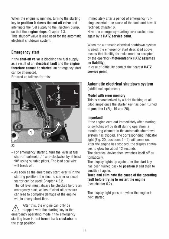
Emergency start
If the shut-off valve is blocking the fuel supplyas a result of an electrical fault and the enginetherefore cannot be started, an emergency startcan be attempted.Proceed as follows for this:
22
– For emergency starting, turn the lever at fuelshut-off solenoid „1“ anti-clockwise by at least90° using suitable pliers. The lead seal wirewill break off.
– As soon as the emergency start lever is in thestarting position, the electric starter or recoilstarter can be used; Chapter 4.2.2.The oil level must always be checked before anemergency start, as insufficient oil pressurecan lead to complete damage of the enginewithin a very short time.
After this, the engine can only bestopped with the starting key in the
emergency operating mode if the emergencystarting lever is first turned back clockwise tothe stop position.
Immediately after a period of emergency run-ning, ascertain the cause of the fault and have itrectified; Chapter 6. Have the emergency-starting lever sealed onceagain by a HATZ service point.
When the automatic electrical shutdown systemis used, the emergency start described abovemeans that liability for risks must be acceptedby the operator (Motorenfabrik HATZ assumesno liability).In case of difficulty contact the nearest HATZservice point.
Automatic electrical shutdown system (additional equipment)
Model with error memoryThis is characterized by a brief flashing of allpilot lamps once the starter key has been turnedto position I (Fig. 19 and 20).
Important !If the engine cuts out immediately after startingor switches off by itself during operation, a monitoring element in the automatic shutdownsystem has tripped. The corresponding indicatorlight (Fig. 20, positions 2 - 4) will come on. After the engine has stopped, the display contin-ues to glow for about 12 seconds. The electrical device then switches itself off au-tomatically. The display lights up again after the start keyhas been turned back to position 0 and then toposition I again.Trace and eliminate the cause of the operatingfault before trying to restart the engine(see chapter 6.2).
The display light goes out when the engine isnext started.
14
Model without error memoryThis model has no specific characteristic whichappears externally. If the engine stops immedi-ately after starting, this indicates a reaction of a monitoring element of the automatic shut-offfeature. Before performing further starting at-tempts, locate and eliminate the malfunction(Chapter 6.2).
Even with automatic shutdown monitoring theoil level must be checked every 8 – 15 operat-ing hours (Chapter 5.2.1.).
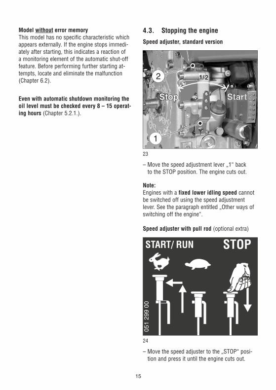
4.3. Stopping the engine
Speed adjuster, standard version
23
– Move the speed adjustment lever „1“ back to the STOP position. The engine cuts out.
Note:Engines with a fixed lower idling speed cannotbe switched off using the speed adjustmentlever. See the paragraph entitled „Other ways ofswitching off the engine“.
Speed adjuster with pull rod (optional extra)
24
– Move the speed adjuster to the „STOP“ posi-tion and press it until the engine cuts out.
15
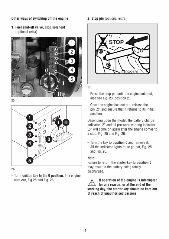
Other ways of switching off the engine
1. Fuel shut-off valve, stop solenoid(optional extra)
25
26
– Turn ignition key to the 0 position. The enginecuts out, Fig 25 and Fig. 26.
�
�
�
�
�
2. Stop pin (optional extra)
27
– Press the stop pin until the engine cuts out,also see Fig. 23, position 2.
– Once the engine has cut out, release the pin „2“ and ensure that it returns to its initialposition.
Depending upon the model, the battery chargeindicator „2” and oil pressure warning indicator„3“ will come on again after the engine comes toa stop, Fig. 25 and Fig. 26.
– Turn the key to position 0 and remove it. All the indicator lights must go out, Fig. 25and Fig. 26.
Note:Failure to return the starter key to position 0may result in the battery being totally discharged.
If operation of the engine is interruptedfor any reason, or at the end of the
working day, the starter key should be kept outof reach of unauthorised persons.
05221301
16
5. Maintenance
Only carry out maintenance work with the engine switched off.Observe all relevant laws and regulations governing the handling and disposal of used oil,
filters and cleaning agents.Protect the starting key against unauthorised use.On engines with an electric starter, disconnect the battery’s negative terminal.When maintenance work has been completed, check that all tools have been removed from theengine and all protective guards fitted again.Before starting the engine, ensure that there are no persons in the danger area close to the engine or equipment.
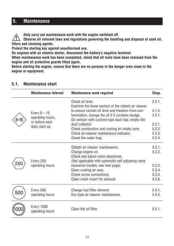
5.1. Maintenance chart
17
Maintenance interval Maintenance work required Chap.
8-15
Every 8 – 15 operating hours, or before each daily start-up
Check oil level.Examine the lower section of the oilbath air cleaner to ensure correct oil level and freedom from con-tamination; change the oil if it contains sludge.On version with cyclone-type dust trap, empty thedust collector.Check combustion and cooling air intake zone.Check air-cleaner maintenance indicator.Check the water trap.
5.2.1.
4.1.2.5.3.1.
5.3.1.5.2.2.5.2.3.5.2.4.
250Every 250operating hours
Oilbath air cleaner maintenance. Change engine oil. Check and adjust valve clearances. (Not applicable with automatic self adjusting valveclearance models, see next page)Clean cooling air area. Check screw connections. Clean mesh insert for exhaust.
5.3.1.5.3.2.
5.3.3.5.3.4.5.3.5.5.3.6.
500Every 500operating hours
Change fuel filter element.Dry-type air cleaner maintenance.
5.4.1.5.4.2.
1000 Every 1000operating hours Clean the oil filter. 5.5.1.

Depending whether the engine is equipped withor without automatic valve clearance adjustmentone of the illustrated maintenance plans is in-cluded. This label should be affixed to the engineor equipment in an easily visible position. Themaintenance chart governs the maintenance in-tervals.
On new or reconditioned engines, after thefirst 25 operating hours, always
– Change engine oil, Chapter 5.3.2.
– Check valve clearances and adjust if necessary,Chapter 5.3.3.
– Examine screw connections, chapter 5.3.5.Do not tighten the cylinder head fastening.
If the engine is not used frequently, change theengine oil after 12 months at the latest, regard-less of the actual number of hours it has been inoperation.
18
AUTOM.
8 -15 250
052 502 00
OILOIL
-40
-30
-20
-10
0
10
20
30
40
50
104
86
68
50
32
14
-4
-22
-40
OIL: SAE...°C°F
5W/3
0
5W/4
0
10W
/40
10W
/30
15W
/40
30
40
122
10WW
1B..
500 1000
Model without automatic valve clearance adjustment.
Model with automatic valve clearance adjustment.
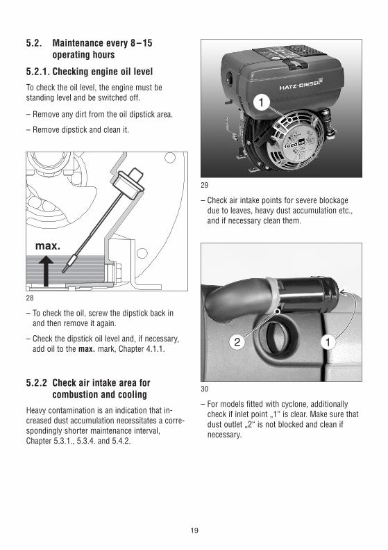
5.2. Maintenance every 8–15 operating hours
5.2.1. Checking engine oil level
To check the oil level, the engine must be standing level and be switched off.
– Remove any dirt from the oil dipstick area.
– Remove dipstick and clean it.
28
– To check the oil, screw the dipstick back inand then remove it again.
– Check the dipstick oil level and, if necessary,add oil to the max. mark, Chapter 4.1.1.
5.2.2 Check air intake area for combustion and cooling
Heavy contamination is an indication that in-creased dust accumulation necessitates a corre-spondingly shorter maintenance interval, Chapter 5.3.1., 5.3.4. and 5.4.2.
max.
29
– Check air intake points for severe blockagedue to leaves, heavy dust accumulation etc.,and if necessary clean them.
30
– For models fitted with cyclone, additionallycheck if inlet point „1“ is clear. Make sure thatdust outlet „2“ is not blocked and clean if necessary.
19
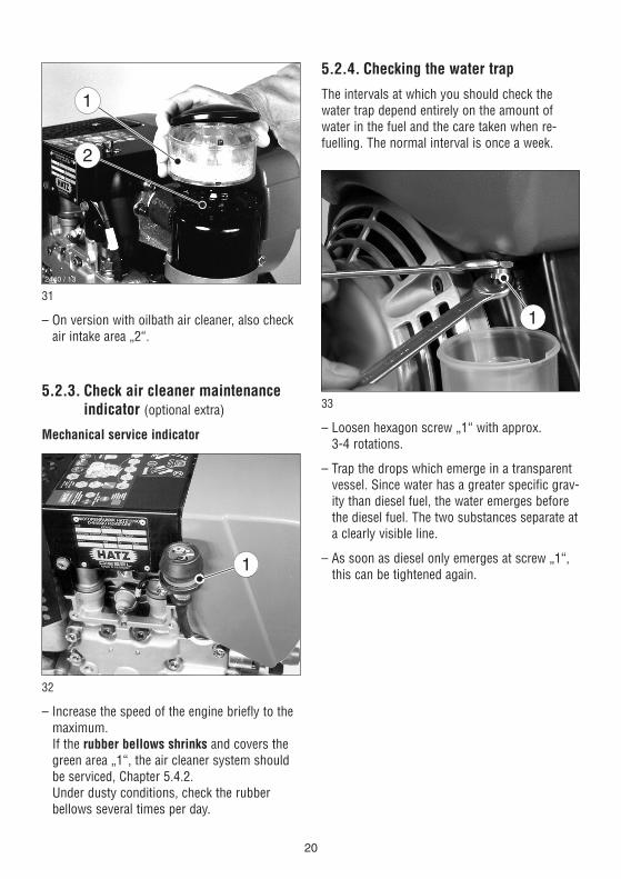
31
– On version with oilbath air cleaner, also checkair intake area „2“.
5.2.3. Check air cleaner maintenance indicator (optional extra)
Mechanical service indicator
32
– Increase the speed of the engine briefly to themaximum. If the rubber bellows shrinks and covers thegreen area „1“, the air cleaner system shouldbe serviced, Chapter 5.4.2. Under dusty conditions, check the rubber bellows several times per day.
1
2440 / 13
5.2.4. Checking the water trap
The intervals at which you should check thewater trap depend entirely on the amount ofwater in the fuel and the care taken when re-fuelling. The normal interval is once a week.
33
– Loosen hexagon screw „1“ with approx. 3-4 rotations.
– Trap the drops which emerge in a transparentvessel. Since water has a greater specific grav-ity than diesel fuel, the water emerges beforethe diesel fuel. The two substances separate ata clearly visible line.
– As soon as diesel only emerges at screw „1“,this can be tightened again.
20

If an external water trap is attached, check itswater content every day, when the engine oillevel is checked. The water which has collectedis separated at a clearly visible line from thediesel fuel above it.
34
– Open drain plug „1“ and drain the water outinto a suitable vessel.
– If the drain plug is difficult to reach, an exten-sion hose can be attached to it.
1
5.3. Maintenance every 250operating hours
5.3.1. Oilbath air cleaner maintenance
35
Trap the old oil and dispose of it in accordance with local legislation.
– Take off the oil tank „1“.
– Remove contaminated oil and sludge from theoil tank, and clean it out.
– Rinse out filter element „2“ in diesel oil; allowit to drip thoroughly and wipe it down beforere-assembling the air cleaner.
– If severely contaminated, clean filter housing „3“.
Never attempt to repair the oilbath air cleaner bywelding, brazing etc., as this could damage thefilter beyond repair and cause engine damage.
– Re-attach parts previously removed from theair cleaner and add oil so that it is ready foruse, Chapter 4.1.2.
2444 / 3
21
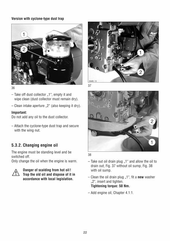
Version with cyclone-type dust trap
36
– Take off dust collector „1“, empty it and wipe clean (dust collector must remain dry).
– Clean intake aperture „2“ (also keeping it dry).
Important:Do not add any oil to the dust collector.
– Attach the cyclone-type dust trap and securewith the wing nut.
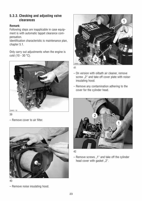
5.3.2. Changing engine oil
The engine must be standing level and beswitched off. Only change the oil when the engine is warm.
Danger of scalding from hot oil ! Trap the old oil and dispose of it in accordance with local legislation.
2440 / 1337
38
– Take out oil drain plug „1“ and allow the oil todrain out, Fig. 37 without oil sump, Fig. 38with oil sump.
– Clean the oil drain plug „1“, fit a new washer„2“, insert and tighten.Tightening torque: 50 Nm.
– Add engine oil, Chapter 4.1.1.
2445 / 3
22
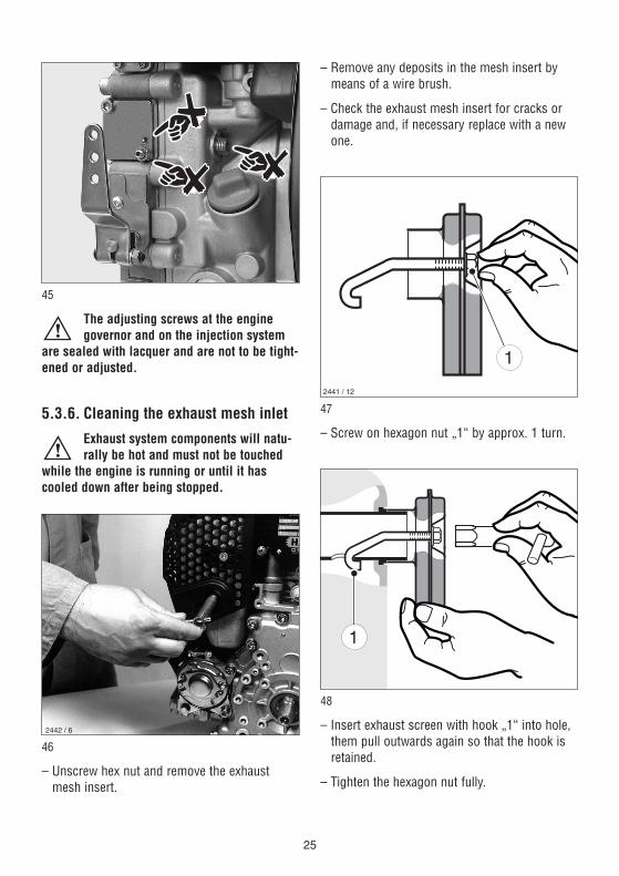
5.3.3. Checking and adjusting valve clearances
Remark:Following steps are inapplicable in case equip-ment is with automatic tappet clearance com-pensation.Identification characteristic is maintenance plan,chapter 5.1.
Only carry out adjustments when the engine iscold (10 - 30 °C).
39
– Remove cover to air filter.
40
– Remove noise insulating hood.
2443 / 12
41
– On version with oilbath air cleaner, removescrew „2“ and take off cover plate with noise-insulating hood.
– Remove any contamination adhering to thecover for the cylinder head.
42
– Remove screws „1“ and take off the cylinderhead cover with gasket „2“.
1
2
2442 / 18
23

43
– Remove rubber cap from the inspection holecover.
– Turn the engine over in the normal direction ofrotation until the valves are in the overlap po-sition (exhaust valve not yet closed, inlet valvestarts to open).
– Turn the crankshaft through 360° in the normal direction of rotation and align exactlyto the OT-marking.
44
– Check valve clearances with feeler gauge „1“(0.10 mm).
1
23
2
3
– If valve clearances require adjusting, slackenoff screw „2“ and turn hex nut „3“ until feelergauge „1“ can be pulled through with justslight resistance when screw „2“ is retight-ened.
– Fit cover for cylinder head and tighten evenly,always using a new gasket.
– Re-attach parts previously removed from engine.Do not forget: replace the rubber cap at the inspection hole cover.
– Carry out a brief test run, then check the coverfor leaks.
5.3.4. Cleaning cooling air area
The engine must be switched off andcooled down before cleaning !
– If severely contaminated, clean the cooling finson the cylinder and cylinder head, and also thefan blades in the flywheel. If necessary, con-tact your local HATZ service station.
5.3.5. Checking screw connections
– Check the tightness of all threaded connec-tions and take up slack if necessary, providedthat these can be reached during maintenancework.Do not tighten the cylinder head bolts.
24
45
The adjusting screws at the enginegovernor and on the injection system
are sealed with lacquer and are not to be tight-ened or adjusted.
5.3.6. Cleaning the exhaust mesh inlet
Exhaust system components will natu-rally be hot and must not be touched
while the engine is running or until it hascooled down after being stopped.
46
– Unscrew hex nut and remove the exhaustmesh insert.
2442 / 6
– Remove any deposits in the mesh insert bymeans of a wire brush.
– Check the exhaust mesh insert for cracks ordamage and, if necessary replace with a newone.
47
– Screw on hexagon nut „1“ by approx. 1 turn.
48
– Insert exhaust screen with hook „1“ into hole,them pull outwards again so that the hook isretained.
– Tighten the hexagon nut fully.
2441 / 12
25
5.4. Maintenance every 500operating hours
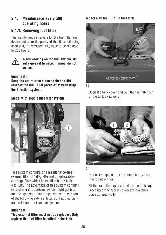
5.4.1. Renewing fuel filter
The maintenance intervals for the fuel filter aredependent upon the purity of the diesel oil beingused and, if necessary, may have to be reducedto 250 hours.
When working on the fuel system, donot expose it to naked flames; do notsmoke.
Important !Keep the entire area clean so that no dirt reaches the fuel. Fuel particles may damagethe injection system.
Model with double fuel filter system
49
This system consists of a maintenance-free external filter „1“ (Fig. 49) and a replaceable-cartridge filter which is installed in the tank (Fig. 50). The advantage of this system consistsin retaining dirt particles which might get intothe fuel system on filter replacement, upstreamof the following external filter, so that they can-not endanger the injection system.
Important !This external filter must not be replaced. Onlyreplace the fuel filter installed in the tank !
Model with fuel filter in fuel tank
50
– Open the tank cover and pull the fuel filter outof the tank by its cord.
51
– Pull fuel supply line „1“ off fuel filter „2“ andinsert a new filter.
– Fit the fuel filter again and close the tank cap.Bleeding of the fuel injection system takesplace automatically.
2441 / 8
26

Model with external fuel filter(no fuel filter in the tank)
– Empty the fuel tank by taking out screw „1“,Fig. 33 or Fig. 34 and allow the fuel to draininto a clean vessel. This fuel can be re-usedlater.
52
– Unscrew the fuel filter from its mount.
– Place a suitable vessel under the filter to trapthe residual fuel.
53
– Pull off fuel supply line „1“ at both ends of fuelfilter „2“ and insert the new filter.
– Always renew the fuel filter. Note the arrowsindicating the correct direction of flow.
– Secure the filter to its mount.
– Fill the fuel tank with diesel oil; Chapter 4.1.3.Air is vented from the fuel system automati-cally.
– Check the fuel filter and lines for leaks after ashort test run.
5.4.2. Air cleaner maintenance
The filter cartridge should only be cleaned whenthe maintenance lamp lights at maximum speed,Chap. 5.2.3. However, the filter cartridge should always be re-placed after 500 operating hours at the latest.
54
– Remove the air cleaner cover.
2443 / 12
27

55
– Unscrew and remove knurled nut „1“ and takeoff air cleaner element „2“.
– Clean the filter compartment and the cover.Dirt and other foreign bodies must not be allowed to enter the engine’s air inlet points.
56
– On versions with a mechanical air cleanerservice indicator, check the condition andcleanliness of valve plate „1“.
– The filter cartridge should either be renewedor, depending upon the degree of contamina-tion, cleaned, or checked, as follows:
1
2442 / 3
Cleaning the filter cartridge
Dry contamination
57
Use compressed air to blow through the filtercartridge from the inside outwards, until no fur-ther dirt emerges.
Important !The pressure must not exceed 5 bar.
Persons handling compressed air mustwear protective goggles.
Moist or oily contamination Renew the filter cartridge.
Checking the filter cartridge
– Check filter cartridge’s gasket surface „1“ fordamage, Fig. 57.
– Check the filter cartridge for cracks or anyother type of damage to the paper filter byholding it inclined towards the light or by shining a light source through it.
Important !The slightest damage to the paper filter rulesout it being used any longer.
– Re-assemble the filter cartridge in the reverseorder of work.
2444 / 10
28

5.5. Maintenance every 1000operating hours
5.5.1. Cleaning the oil filter
The oil filter should be cleaned at the same timeas the engine oil is changed, since oil escapeswhen the filter is removed.
The engine must be standing horizontally andswitched off.
Danger of scalding from hot oil !Trap the old oil and dispose of it in accordance with local legislation.
58
– Loosen screw „1“ with approx. 5 rotations.
59
– Remove oil filter from housing.
60
– Use an air line to blow out oil filter dirt fromthe inside outwards.
Persons handling compressed air mustwear protective goggles.
2445 / 10
29

61
– Check joint washer „1“ whether it is damage;replacement if necessary.
– Check joint washer „2“ whether it is damageand correctly fitted, replace oil filter if neces-sary.
– Lubricate joint washer before fitting.
62
– Put in oil filter and press until limit stop.
– Check whether tension springs sit close to oilfilter with both ends „1“, before tighteningscrew.
– Check the oil level and restore to the max.level if required, Chapter 4.1.1.
30

6. Malfunctions – causes and remedies
Malfunctions Possible causes Remedy Chap.
31
6.1. Engine does notstart, or not imme-diately, but can beturned over easilyas usual.
At lowtemperatures.
Speed control lever in stop oridle position.
Engine shutdown pin in STOPposition.
No fuel in the injection pump.
Insufficient compression:- Incorrect valve clearance.
- Cylinders and/or piston rings worn.
Injector not functioning.
Below starting thresholdtemperature.
Equipment not disengaged.
Preheating system faulty(optional extra).
Fuel has inadequate resistanceto low temperatures.
Move lever to START position.
Move to operating position bypulling the pin gently.
Add fuel.Systematically check the entirefuel supply system:If still no fault found,- check engine feed line- check fuel filter
Check valve clearances, adjust ifnecessary.
See workshop manual.
See workshop manual.
Operate preheater (optional extra).
Disengage engine from equip-ment, if possible.
See workshop manual.
Check whether clear (not turbid)fuel emerges at the fuel line de-tached from the injection pump.If turbid or separated - eitherwarm up the engine or drain thecomplete fuel supply system.Refill with winter-grade fuel towhich paraffin has been added.
4.2.1.
4.3.
4.1.3.
5.4.1.
5.3.3.
4.2.3.
4.1.3.
32
Malfunctions Possible causes Remedy Chap.
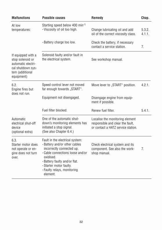
At low temperatures:
If equipped with astop solenoid orautomatic electri-cal shutdown sys-tem (additionalequipment)
6.2.Engine fires butdoes not run.
Automatic electrical shut-offdevice (optional extra)
6.3.Starter motor doesnot operate or en-gine does not turnover.
Starting speed below 400 min-1
- Viscosity of oil too high.
- Battery charge too low.
Solenoid faulty and/or fault inthe electrical system.
Speed control lever not movedfar enough towards „START“.
Equipment not disengaged.
Fuel filter blocked.
One of the automatic shut-down’s monitoring elements hasinitiated a stop signal.(See also Chapter 6.4.)
Fault in the electrical system:- Battery and/or other cablesincorrectly connected up.
- Cable connections loose and/oroxidised.
- Battery faulty and/or flat.- Starter motor faulty.- Faulty relays, monitoring element.
Change lubricating oil and addoil of the correct viscosity class.
Check the battery, if necessarycontact a service station.
See workshop manual.
Move lever to „START“ position.
Disengage engine from equip-ment if possible.
Renew fuel filter.
Localise the monitoring elementresponsible and clear the fault,or contact a HATZ service station.
Check electrical system and itscomponent. See also the work-shop manual.
5.3.2.4.1.1.
7.
4.2.1.
5.4.1.
7.

Malfunctions Possible causes Remedy Chap.
33
Fuel supply interrupted- Tank has run empty.- Fuel filter blocked.- Tank venting inadequate.- Air in the fuel system.
Mechanical faults.
One of the automatic shutdown’smonitoring elements has initiat-ed a stop signal.
Monitoring element for:- oil pressure too low- engine temperature too high
- defective alternator.
Fuel supply interrupted:- Tank has run empty.- Fuel filter blocked.- Tank breathing inadequate.- Air in the fuel system.
- Speed control lever does notremain in desired position.
Air cleaner contaminated.
Valve clearances incorrect.
Injector not functioning.
Add fuel.Change fuel filter.Ensure adequte tank venting.Check fuel system for penetration of air.Check air vent valve.
Contact a HATZ service station.
Localise the monitoring elementresponsible and clear the fault,or contact a HATZ service station.
Check oil lubrication.Check air cooling zone for con-tamination.See workshop manual.
Add fuel.Change fuel filter.Provide adequate tank breathing.Check fuel system for penetration of air.Check air vent valve.
Lock the lever into position.
Clean or renew the air cleaner.
Adjust valve clearances.
See workshop manual.
4.1.3.5.4.1.
5.2.1.
5.3.4.
4.1.3.5.4.1.
5.3.1.5.4.2.5.3.3.
6.4.Engine cuts out ofits own accordduring operation.
Automatic electrical shut-offdevice (optional extra)
6.5.Engine output andspeed both drop.
6.6.Engine output andspeed fall, blacksmoke from ex-haust.

Malfunctions Possible causes Remedy Chap.
34
6.7.Engine becomesvery hot. Indicatorlamp for cylindertemperature (optional extra)comes on.
6.8.Moisture conden-sate emergingfrom exhaust.
Too much lubricating oil in engine.
Inadequate cooling:- Contamination of entire cooling air zone.
- Air duct panels notproperly sealed.
Operation off load for a prolonged period.
Drain off lubricating oil as far asupper mark on dipstick.
Clean cooling air zone.
Check cooling air deflectorplates and shafts for complete-ness and airtight seal.
Operate the machine at about 70 % load until moisture nolonger emerges from the ex-haust.
5.3.2.
5.3.4.
7. Work on the electricalsystem
Batteries generate explosive gases.Keep them away from naked flame and
sparks which could cause them to ignite. Do not smoke. Protect eyes, skin and cloth against the corro-sive battery acid. Pour clear water over acidsplashes immediately. In case of emergencycall doctor.Do not place any tools on top of the battery.
Always disconnect the negative (–) pole of thebattery before working on the electric device.
– Do not confuse the positive (+) and negative (–) terminals of the battery.
– When fitting the battery, first connect up thepositive lead, then the negative lead.Negative terminal to earth = engine block.
– When removing, first disconnect the negativelead, then the positive lead.
– Always take care to avoid short-circuits andearth (ground) contact of live cables.
– If malfunctions occur, first of all check thatcable connections make good contact.
– Replace a failed indicator light without delay.
– Do not remove the ignition key while the en-gine is running.
– Do not disconnect the battery while the en-gine is running.Electric voltage peaks can cause damage toelectrical components.
– In case of an emergency start in manualmode, leave the battery (which might be dis-charged) connected to the engine.
– Before starting emergency operation withoutbattery, proceed as follows before starting:- disconnect plug-connection to voltage regulator for engine models with mountedinstrument box (picture 25).Turn key to off-position (0) and remove.
- disconnect plug-connection to instrumentbox for engine models with external instrument box (picture 26).
– Do not splash electrical device with water jetor pressure jet during engine cleaning.
– When carrying out welding work on the en-gine or equipment, fit the earth clip of thewelding equipment as close to the weldingpoint as possible and disconnect the battery.The connecting plug for the voltage regulatormust be removed.
The relevant circuit diagrams are enclosed withthe engine if it is equipped with an electrical sys-tem. Additional circuit diagrams can be suppliedto order.
HATZ assumes no liability for electrical systemswhich was not carried out acc. HATZ circuit dia-grams.
8. Storage out of use
The new engine can normally be stored dry forup to one year. In very humid climates or coastal regions, theprotective treatment is sufficient for up to about6 months. For longer periods of storage, please contactyour nearest HATZ service station.
35

CALIFORNIA
Proposition 65 Warning
Diesel engine exhaust and some of itsconstituents are known to the Stateof California to cause cancer, birthdefects, and other reproductive harm.


![M60 LED Direct [l60] selux€¦ · 6 . See page 7 for full details . 7 . Not available for 1’ length or with 1B45 or 1B40. 8 . 120V only. 9 . EM option not available in 4’ length.](https://static.fdocuments.in/doc/165x107/5f06c8fa7e708231d419b8c8/m60-led-direct-l60-selux-6-see-page-7-for-full-details-7-not-available-for.jpg)
