
Instructio n manual UniGear ZS3.2 Air-insulated … · 7.4.1 Checking the auxiliary ... Strictly...
40
UniGear ZS3.2 Air-insulated medium voltage switchgear Instruction manual 1 Summary 1.1 General 1.2 Standards and specifications 1.3 Service conditions 1.3.1 Normal service conditions 1.3.2 Special service conditions 2 Technical data 2.1 Electrical data 2.2 Resistance to internal arc faults 2.3 Dimensions and weights 3 Switchgear panel structure and equipment installed 3.1 Basic structure and variants 3.2 Enclosure and partitions 3.3 Compartments in the switchgear panels 3.4 Interlocks/protection against maloperation 3.5 Main apparatuses 3.5.1 Circuit breaker 3.5.2 Instrument transformers 3.5.3 Surge arrester 3.5.4 Eearthing switch 4 Dispatch and storage 4.1 Condition on delivery 4.2 Packaging 4.3 Transport 4.4 Delivery and intermediate storage 5 Assembly of the switchgear at site 5.1 General site requirements 5.2 Foundation frame on a concrete floor 5.3 Assembly of the switchgear panels 5.4 Installation of the busbars and bushings 5.5 Connection of the power and control cables 5.6 Earthing the switchgear 5.7 Concluding installation work 6 Operation of the switchgear 6.1 Commissioning 6.1.1 Preparatory work 6.1.2 Start-up 6.2 Switching operations 6.2.1 Withdrawable circuit-breaker part 6.2.2 Circuit-breaker 6.2.3 Earthing switch 3 3 3 3 3 3 4 4 4 4 6 6 6 6 7 8 8 9 9 9 15 15 15 15 15 17 17 17 18 19 19 19 19 28 28 28 28 28 28 29 29 6.3 Test procedures 6.3.1 Testing the off-circuit condition 6.3.2 Testing for in-phase condition 7 Maintenance 7.1 General 7.2 Inspection and servicing 7.3 Repair 7.3.1 Switchgear surface 7.3.2 Replacement of components 7.4 Tests on withdrawable parts with circuit-breakers of VD4 or HD4 7.4.1 Checking the auxiliary switch settings on withdrawable parts 7.4.2 Testing of interlock conditions 7.5 Tests on the switchgear panel 7.5.1 Auxiliary switch setting on the earthing switch 7.6 Spare parts, auxiliary materials and lubricants 7.6.1 Spare parts 7.6.2 Auxiliary materials and lubricants 8 Product quality and environmental protection 29 29 30 34 34 34 35 35 35 35 35 36 37 37 37 37 37 39
Transcript of Instructio n manual UniGear ZS3.2 Air-insulated … · 7.4.1 Checking the auxiliary ... Strictly...

UniGear ZS3.2Air-insulated medium voltage switchgear
Instruction manual
1 Summary1.1 General1.2 Standards and specifications1.3 Service conditions1.3.1 Normal service conditions 1.3.2 Special service conditions
2 Technical data2.1 Electrical data2.2 Resistance to internal arc faults2.3 Dimensions and weights
3 Switchgear panel structure and equipment installed3.1 Basic structure and variants3.2 Enclosure and partitions3.3 Compartments in the switchgear panels3.4 Interlocks/protection against maloperation3.5 Main apparatuses3.5.1 Circuit breaker3.5.2 Instrument transformers3.5.3 Surge arrester3.5.4 Eearthing switch
4 Dispatch and storage4.1 Condition on delivery4.2 Packaging4.3 Transport4.4 Delivery and intermediate storage
5 Assembly of the switchgear at site5.1 General site requirements5.2 Foundation frame on a concrete floor5.3 Assembly of the switchgear panels5.4 Installation of the busbars and bushings5.5 Connection of the power and control cables5.6 Earthing the switchgear5.7 Concluding installation work
6 Operation of the switchgear6.1 Commissioning6.1.1 Preparatory work6.1.2 Start-up 6.2 Switching operations6.2.1 Withdrawable circuit-breaker part6.2.2 Circuit-breaker6.2.3 Earthing switch
333333
4444
6
666788999
1515151515
1717171819191919
2828282828282929
6.3 Test procedures6.3.1 Testing the off-circuit condition6.3.2 Testing for in-phase condition
7 Maintenance7.1 General7.2 Inspection and servicing7.3 Repair7.3.1 Switchgear surface7.3.2 Replacement of components7.4 Tests on withdrawable parts with circuit-breakers of VD4 or HD47.4.1 Checking the auxiliary switch settings on withdrawable parts7.4.2 Testing of interlock conditions 7.5 Tests on the switchgear panel7.5.1 Auxiliary switch setting on the earthing switch7.6 Spare parts, auxiliary materials and lubricants 7.6.1 Spare parts7.6.2 Auxiliary materials and lubricants
8 Product quality and environmental protection
292930
34343435353535
35
363737373737
39

Make sure that the installation room (spaces, divisions and ambient) is suitable for the electrical apparatus
Check that all the installation, putting into service and maintenance operations are carried out by qualified personnel with suitable knowledge of the apparatus
Make sure that the standard and legal prescriptions are complied with during installation, putting into service and maintenance, so that installations according to the rules of good working practice and safety in the work place are constructed
Strictly follow the information given in this instruction manual
Dangerous
Pay special attention to the danger notes indicated in the manual by the following symbol
Check that the rated performance of the apparatus is not exceeded during service
Check that the personnel operating the apparatus have this instruction manual to hand as well as the necessary information for correct intervention
Responsible behavior safeguards your own and others’ safety
For any requests, please contact the ABB Assistance Service.
For your safety!

1.1 GeneralThe metal-enclosed, three-pole air-insulated switchgear panels without disconnectors of UniGear ZS3.2 series are fac-tory-assembled, type-tested indoor panels for a rated voltage of 36/40.5 kV. They are designed as withdrawable module type panels, and fitted with a single busbar system. The with-drawable parts are fitted with vacuum circuit-breakers.
Details of the technical design and configuration of individual switchgears, such as the technical data, detailed equipment lists for the individual panels and comprehensive circuit doc-umentation, etc., can be found in the relevant order docu-ments.
1.2 Standards and specificationsUniGear ZS3.2 switchgear panels comply with the standards and specifications for factory-assembled and type tested high voltage switchgears to IEC publications 62271-200 and 62271-100. In addition, in accordance with IEC 60529, the switchgear panels have degrees of protection
IP 4X for the enclosure andIP 2X for the partitions.
The corresponding IEC publications, the national or local safe-ty at work regulations and the safety regulations for produc-tion materials are to be followed during erection and operation of these systems. Above and beyond this, the order-related data from ABB Xiamen Switchgear Co., Ltd. are to be taken into account.
1.3 Service conditions1.3.1 Normal service conditionsThe switchgears are fundamentally designed for the normal service conditions for indoor switchgears IEC publication 62271-1. The following limit values, among others, apply:
■ Ambient temperature: ■ Maximum +40° C ■ Maximum 24 h average +35° C ■ Minimum (according to “minus 15 indoor class”) -15° C
■ Humidity ■ Highest average value measured over 24 hours Relative humidity 95 % ■ Highest average value measured over 1 month Relative humidity 90 %
Remark:With indoor installation, it is assumed that the humidity within the enclosure can reach high values, but that there is normally no condensation on the installed equipment. Condensation can be prevented by appropriate configuration of the station building or switchgear room.
The maximum site altitude is 1000 m above sea level.
1.3.2 Special service conditionsAccording to IEC 62271-100, the manufacturer and user may agree on special service conditions which deviate from the normal service conditions. The manufacturer must be consult-ed in advance about each special service conditions.
Examples are as follows:■ At site altitudes above 1000 m, the effects of the reduction in dielectric strength of the air on the insulation level are to be taken into account
■
1 Summary
UniGear ZS3.2 air-insulated medium voltage switchgear | Summary 03
Increased ambient temperatures must be compensated for in the design of the busbars and tee-off conductors, or the current carrying capacity will be limited. Heat dissipation in the switchgear panel can be assisted by fitting additional ventilation facilities

04 Technical data | UniGear ZS3.2 air-insulated medium voltage switchgear
Standard: IEC/Chinese GB Russian GOST
Rated voltage kV 36/40.5 Unorm.: 35 Umax.: 40.5
Rated power frequency withstand voltage/1 min kV 70/95
Rated lightning impulse withstand voltage kV 170/185 190
Rated frequency Hz 50
Rated current of busbars A 1250, 1600, 2000, 2500, 3150
Rated current of tee-offs, circuit-breaker A 1250, 1600, 2000, 2500, 31503)
Rated peak withstand current1) kA 63, 80
Rated short-circuit breaking kA 25, 31.5
Current of circuit-breaker
Rated short-time current 4 s1) kA 25, 31.5
Auxiliary voltage V DC2) 110, 220, AC 110, 220
1) Take the short-circuit withstand capability of the instrument transformers into account separately.2) Special DC voltages on request.3) Up to 3150 A at 40°C and 2500 A at 55°C with forced ventilation.
2.2 Resistance to internal arc faultsThe switchgear units have been tested in according with IEC 62271-200 (Annex A, class A, criteria 1 to 5), the switch-gear units are classified as IAC AFLR 31.5 kA for 1 s.
2.3 Dimensions and weights(Figure 2/1 and 2/2)Dimension according to Figures 2/1 and 2/2 Weight: 1100 kg to 2000 kg, according to the equipment installed.
2 Technical data
2.1 Electrical data

A Circuit-breaker compartmentB Low-voltage compartmentC Busbar compartmentD Cable connection compartment
C
D
R(L1)
Y(L2)
B(L3)
Service
Position Test
Position
2350
30 2500 35450
2400
A B
Figure 2/1: Dimensions, without ventilation, front view
Figure 2/2: Dimension, UniGear ZS3.2, …1600 A, section view Figure 2/1
Figure 2/2
UniGear ZS3.2 air-insulated medium voltage switchgear | Technical data 05
2400
1200 55
47

06 Switchgear panel structure and equipment installed | UniGear ZS3.2 air-insulated medium voltage switchgear
3.1 Basic structure and variants(Figures 3/1 to 3/6)The basic structure of the switchgear panels comprises the panel itself, which is fixed in position, and the movable, withdrawable part with vacuum circuit-breaker. Figures 3/1 to 3/6 show the structure of a panel and the electrical equip-ment fitted. The whole panel is constructed by bolting up the double folded components manufactured from high quality Al-Zn sheet steel, precisely folded and exactly fitted surface from and extremely rigid construction. Illustration shows the structure of a panel and the electrical equipment fitted. To-gether with the basic panel version for use as an incoming or outgoing feeder panel, variants, for example for busbar sec-tionalizing (in conjunction with a bus riser panel) or metering, are available. Further details on the structure and equipment configuration of the switchgears can be taken from the order documents for the particular case.
The panel consists of the following components■ Circuit-breaker compartment■ Busbar compartment■ Cable connection compartment■ Low voltage compartment
The compartments are seperated from each other by earthed sheet steel partitions.
3.2 Enclosure and partitions(Figures 3/1 to 3/6)The enclosure and internal partitions of the switchgear panels consist of high quality aluminium zink coated sheet steel. The three high-voltage compart-ments are fitted with secured pressure relief plates located at the top. These open upward if internal arc faults result in overpressure. The front and rear of the panels is closed off by flameproof doors which open to an angle of almost 180°. Neighbouring switchgear panels are partitioned from one another by the side walls of each panel and the air cushion which remains between these walls as a result of the design when the panels are joined together. This method of construction prevents them from melting through if an arc fault should occur. All heads of the structure bolts do not stick up the fitting surface on the side walls as result of embossing processing used. Thanks to that, it is possible to remove the middle panel of the switchgear without removing the adjacent panels. The separately fitted low-voltage com-partment B is designed as a self-supporting shockproof and flameproof sheet steel enclosure, separate from the high-volt-age area. Even with the withdrawable part 50 removed (hinged shutters 35.1/ 35.2 in the closed position), there is protection against contact with live parts in busbar compartment C and cable connection compartment D.
The necessary safety measures to counteract the effects of an internal arc fault must be ensured in connection with the ceiling height. This may in individual cases possibly necessi-
tate additional operator protection measures on the switch-gear panels.
The front and rear doors of the switchgear panels and the cover plates of the end panels are thoroughly cleaned, treated to prevent corrosion, and then painted with a high-quality two-coat stoved enamel system in colour RAL7035 (or special colours as agreed) which are notable after stoving for their particular insensitivity to impacts and corrosion.
3.3 Compartments in the switchgear panelsCircuit-breaker compartment(Figures 3/6, 3/9 to 3/13)The circuit-breaker compartment A fitted with the necessary guide rails accommodates the withdrawable part 50, which can be moved between the service position and the test/dis-connected position.
If the withdrawable part is moved from the service position into the test/disconnected position, the fixed contacts 25.1 located in the connection block 20.1/20.2 in busbar compart-ment C and cable connection compartment D are automatical-ly covered by metal plates which will be interlocked mechan-ically or can be locked by a padlock when the withdrawable part is moved away. In the test/ disconnected position, the withdrawable part is still completely inside the panel with the door closed.
The switching operations (including manual operation) are carried out with the doors closed.
Withdrawable part(Figures 3/1, 3/2, 3/14, 3/15, 3/16, 3/17, 6/1 to 6/7)The manually moved withdrawable part consists of a robust sheet steel structure on which the circuit-breaker poles are mounted and the breaker mechanism with anciallary compo-nents are installed.
Contact arms 57.1/57.2 with spring-loaded contact systems are fitted to the circuit-breaker poles. These create the electri-cal connection to the switchgear panel when the withdrawable part is inserted into the service position. Detail information on the vacuum circuit-breaker can be found in the corresponding instruction manual.
The signalling, protection and control wiring between the switchgear panel and the withdrawable part is coupled by a multiple pin control wiring plug connector 10.
As soon as withdrawable part 50 has been slid into the switchgear panel and its interlock yoke 51 has engaged in the test/disconnected position, it is positively connected to the switchgear panel. At the same time, it is earthed by earthing contacts 50.1 and earthing rail 19/19.1. The position of the withdrawable part can be checked on the electrical position
3 Switchgear panel structure and equipment installed

indicator or through the sight glass in the door at any time. The stored-energy spring mechanism of the circuit-breaker including controls and indicators is accessible at the front of the withdrawable part. Apart from the version with a fitted circuit-breaker, withdrawable parts with other equipment, e.g. for metering, are available.
Busbar compartment(Figures 3/6, 5/7 to 5/17)Busbars 3 are laid in sections from panel to panel, and are held in place by the tee-off conductors 3.1 and by busbar bushings 29. The conductor material used is tubing with a D-shaped cross-section, in either single or double configura-tion depending on the current rating, or rectangle copper bar. The connection to the flat tee-off conductors is made without any special connecting clamps. The busbars and tee-off con-ductors are covered with shrink-on sleeves. The bolt connec-tions in the busbar system are normally covered by insulating covers 58. In conjunction with bushings 29, panel by panel partitioning is realised.
Cable connection compartment(Figures 3/6, 5/5, 5/6, 6/10 to 6/12)Current transformers and an earthing switch (with manual operating mechanisms) are located here. Installation of surge arrestors is possible. Multiple parallel power cables can also be entered without difficulty. The cable sealing ends 16 can be fitted in particularly favourable conditions. A removeable plate for cable glands is located in the cable entry area.
Installation of voltage transformers at cable side of the panel is in preparation and will have influence on the depth of the panel.
The earthing switch is designed with a making capacity of 80 kA.
The detailed information on the earthing switch can be found in the corresponding instruction manual.
Low-voltage compartment(Figures 3/6)The low-voltage compartment, together with its front door, accommodates the secondary equipment of the switchgear panel required for the particular application.
The control wiring in the switchgear panel area is led through generously dimensioned and metal covered ducts. The left-hand duct is reserved for the incoming and outgoing control wires, and the internal wiring in the panel is located on the righthand side.
At the top of the left hand duct, an entry for control cables is reserved with the free-cut rubber sealing which will keep the pro-tection class IP4X for the whole encloser of the switchgear panel.
3.4 Interlocks/protection against maloperation(Figures 3/6, 3/10 to 3/12, 6/1 to 6/8)A series of interlocks are provided to prevent fundamentally hazardous situations and maloperation, thus protecting both personnel and the switchgear itself. The interlocks which are normally individually effective are as follows:
■ The withdrawable part can only be moved from the test/disconnected position into the service position (and back) with the circuit-breaker open and the earthing switch open (between positions, the circuit-breaker is mechanically interlocked, and also electrically interlocked in the case of circuit-breakers with electrical releases)
■ The circuit-breaker can only be closed when the with-drawable part is precisely in the defined test position or ser-vice position. Between these positions, the circuit-breaker is mechanically interlocked, and also electrically interlocked in the case of circuit-breakers with electrical releases
■ The circuit-breaker can only be opened manually in the ser-vice or test position when no control voltage is applied, and cannot be closed (electro-mechanical interlock)
■ Low-voltage plug 10.2 can only be inserted or removed when the withdrawable part is in the test/disconnected po-sition
■ Earthing switch 6 can only be closed when the withdrawable part is in the test/disconnected position or the removed position (mechanical interlock)
■ The withdrawable part cannot be moved from the test/disconnected position into the service position when the earthing switch is closed (mechanical interlock)
■ Details of any additional interlocks, e.g. in connection with a blocking magnet on the withdrawable part and/or earth-ing switch operating mechanism, can be found in the order documents for each individual case (see also section 7.4)
■ eht ni skcoldap htiw deruces eb nac srettuhs degnih ehT closed position when the withdrawable part has been re-moved (Figure 3/9)
UniGear ZS3.2 air-insulated medium voltage switchgear | Switchgear panel structure and equipment installed 07

08 Switchgear panel structure and equipment installed | UniGear ZS3.2 air-insulated medium voltage switchgear
3.5 Main apparatuses3.5.1 Circuit breakerVacuum circuit breaker VD4The vacuum circuit breaker of type VD4 on withdrawable parts for 36/40.5 kV rated voltage are intended for indoor installation in air-insulated switchgear systems. Their switching capacity is sufficient to handle any conditions arising from switching of equipment and system components under normal operating and fault conditions, particularly short-circuits,within the parameters of their technical data.
Vacuum circuit breakers have particular ad-switching frequen-cy in the working current range and/or where a certain number of short-circuit breaking operations are expected. Type VD4 vacuum circuit breakers are suitable for autoreclosing, and have exceptionally high operating reliability and long life.
The vacuum circuit breakers designed in column form, are supplied as withdrawable modules.
SF6 circuit breaker HD4HD4 medium voltage circuit-breakers use sulphur hexafluoride gas (SF6) to extinguish the electric arc and as the insulating medium.
SF6 has smooth breaking characteristics, therefore breaking in SF6 gas takes place without any arc chopping and without generation of overvoltages.
These characteristics ensure long electrical life of the circuit breaker and limited dynamic, dielectric and thermal stresses on the installation.
The circuit-breaker poles, which make up the breaking part, are systems with lifelong sealed pressure and are mainte-nance-free.
The ESH type mechanical operating mechanism of HD4, with stored energy has free release and allows opening and closing operations independently of the operator’s actions.
The operating mechanism and the poles are fixed to the metal structure which also acts as a support for the kinetics for op-erating the moving contacts.
Circuit-breakers in the withdrawable version are fitted with a truck to allow racking in and racking out of the switchboard or enclosure.
The light and compact structure of the circuit-breaker ensures great sturdiness and excellent mechanical reliability.
Figure 3/1 VD4 Figure 3/2 HD4/Z
3 Switchgear panel structure and equipment installed

UniGear ZS3.2 air-insulated medium voltage switchgear | Switchgear panel structure and equipment installed 09
3.5.2 Instrument transformersCurrent transformersThe current transformers are of the type insulated in resin and are used to supply the measurement devices and protection instruments. These transformers have a wound core with one or more cores, with performances and accuracy classes suit-able for the installation requirements.
Voltage transformersThe voltage transformers are of the type insulated in resin and are used to supply measurement and protection devices. They are available for fixed assembly or for installation on remov-able and withdrawable trucks.
When they are installed on removable or withdrawable trucks they are fitted with medium voltage protection fuses. The withdrawable trucks also allow replacement of the fuses with the switchgear in service. Truck racking-out with the door closed automatically operates closure of a metallic segrega-tion shutter between the live parts of the switchgear and the instrument compartment.
3.5.3 Surge arresterProtection of medium voltage AC networks against both, mul-tiple atmospheric and switching overvoltages as well as Very Fast Transients (VFT). Suitable for instance for the protection of transformers, cables, motors and other medium voltage equipment.
3.5.4 Eearthing switchEarthing switches of Series EK6 are determined for indoor installation and fitted with snap-action operating mechanisms for positive high-speed closing and sufficiently dimensioned to conduct the rated short-circuit making current when closed under load. The speed of the snap-action closing operation is independent controls. The earthing swithes are supplied as kits with a pre-assembled active part and corresponding earth-ing contacts supplied lose. Correct installation of these parts in a switchgear panel results in a functioning earthing earth.
AdvantagesLow residual voltage■ Long protection distance■ High energy input capacity■ Stable U-I characteristics even after multiple strokes■ Proof against ageing■ Explosion and shatter-resistant design■ Pollution resistant and UV-stable■ Housing resistant to rough handling■ Maintenance free■ Stable against shock and vibration■ High mechanical resistance
Figure 3/3 MWK Figure 3/4 EK6-4008-280

10 Switchgear panel structure and equipment installed | UniGear ZS3.2 air-insulated medium voltage switchgear
14 Earthing switch, operation mechanism14.1 Hexagonal shaft14.2 Slide52 Spindle54 ON-OFF operating shaft54.4 Labels for operating advice54.5 Sight glass54.6 Ventilation grit below (optional)
Figure 3/5: UniGear ZS3.2, front view.
3 Switchgear panel structure and equipment installed

UniGear ZS3.2 air-insulated medium voltage switchgear | Switchgear panel structure and equipment installed 11
A Circuit-breaker compartmentB Low-voltage compartmentC Busbar compartmentD Cable compartment1 Enclosure1.1 Pressure relief plate1.2 Control wiring duct3 Busbar3.1 Tee-off conductor, busbar side3.2 Tee-off conductor, cable side5 Insulated separating plate6 Earthing switch9.1 Current transformer10 Control wiring plug connector10.1 Control wiring socket10.2 Control wiring plug10.3 Interlocking arm for wiring plug14 Earthing switch operation mechanism14.1 Hexagonal shaft16 Cable sealing ends
17 Floor cover plate17.2 Reducer ring19 Main earthing bar20.1 Spout, above20.2 Spout, below21 Cable clamp23 Cable connection point28 Bushing plate29 Busbar bushing30 Front door for circuit-breaker compartment30.1 Rear panel cover, above30.2 Rear panel cover, below35.1 Hinged shutter system, above35.2 Hinged shutter system, below50 Withdrawable part (with circuit-breaker, type VD4 or HD4)50.2 Front partition plate51 Interlock yoke52 Spindle
28
3
3.1
Y(L2)
B(L3)
HEATING PLATE
R(L1)
29
30.1
29.1
5
6
20.2
3.2
30.2
23
16
9.1
21
17.2
19
17
A BC
D
35.1
1
1.2
30
50.2
14, 14.1
50
52
51
35.2
10, 10.1, 10.2
10.3
Figure 3/6: UniGear ZS3.2 section view, basic structure of an incoming or
outgoing feeder panel, …1600 A.

12 Switchgear panel structure and equipment installed | UniGear ZS3.2 air-insulated medium voltage switchgear
Figure 3/8: Panel of type UniGear ZS3.2, rear side | Figure 3/9: Circuit-breaker
compartment, door open, withdrawable part removed
Figure 3/10: Circuit-breaker compartment, door open, withdrawable part in
isolated/disconnected position.
30.2
30.1
30.1 Rear cover, above30.2 Rear cover, below
35.3
35.1
35.243.1
44
19.1
Figure 3/8 Figure 3/9
19.1 Earthing rail35.1 Hinged shutter system, above35.2 Hinged shutter system, below
Control wiring plug connection engaged.10 Control wiring plug connector14 Earthing switch, operation mechanism14.1 Hexagonal shaft14.2 Slide50 Withdrawable part (with circuit-breaker, type VD4 or HD4) 50.2 Front partition plate51 Interlock yoke
Figure 3/10
5050.2
1414.114.2
51
10
3 Switchgear panel structure and equipment installed
35.3 Fishplate for inserting a padlock43.1 Duct cover for control cables44 Heater

20.1
25.1
20.2
UniGear ZS3.2 air-insulated medium voltage switchgear | Switchgear panel structure and equipment installed 13
Figure 3/11: Circuit-breaker compartment, door open, withdrawable part in
service position
Figure 3/12: Circuit-breaker compartment withdrawable part in service position
Figure 3/13: View into circuit-breaker compartment withdrawablepart removed,
hinged shutters opened
Figure 3/14: Withdrawable part with circuit breaker, HD4 operation side
20.1 Spout, above20.2 Spout, below25.1 Contact pin, ...1600 A
Figure 3/11
Figure 3/13
10.1
10.2
10.3
Figure 3/12
Figure 3/14
Control wiring plug connection engaged.Interlocking arm not in blocking position.10.1 Control wiring socket10.2 Control wiring plug10.3 Interlocking, for control wiring plug, disengaged

50.2
57.1
57.8
57.2
50.1
50.8
14 Switchgear panel structure and equipment installed | UniGear ZS3.2 air-insulated medium voltage switchgear
9.2 Voltage transformer50 Frame of the withdrawable part50.2 Front partition plate50.3 Pin (for opening the shutter)50.4 Guide cam
50.2
9.2
50
50.3
50.4
50.1 Earthing contact50.2 Front partition plate50.8 Wheel57.1 Upper contact arm57.2 Lower contact arm57.3 Contact system57.8 Embedded pole
Figure 3/15: Withdrawable part with circuit-breaker, VD4,operating mechanism
side control wiring plug pluged at front partition of the circuit-breaker
Figure 3/16: Withdrawable part with circuit-breaker,VD4, operating side
Figure 3/17: Withdrawable part with metering unit, left and operator‘s side view
Figure 3/15
Figure 3/17
Figure 3/16
3 Switchgear panel structure and equipment installed

UniGear ZS3.2 air-insulated medium voltage switchgear | Dispatch and storage 15
4.1 Condition on deliveryThe factory assembled switchgear panels are checked at the works for completeness in terms of the order and simultaneously subjected to routine testing (normally without AC voltage testing of the busbars) to IEC publication 62271-200, and thus tested for correct structure and function.
The busbars are not assembled at factory. The busbar material, fasteners and accessories are packed separately.
4.2 PackagingThe switchgear panels are despatched in appropriate packaging for the prevailing conditions, e.g. “seaworthy packaging”, or also without packaging, as required in individual cases. Particularly for over-seas transport, even in containers, they are sealed in airtight plastic sheeting with an appropriate quantity of drying agent to protect them from damage due to moisture, and in many cases fitted with a separate moisture indicator. When aluminium com-posite sheeting is used, a window has to be fitted for observation of the moisture indicator. The drying agent is active as long as the coloured indicator remains blue. When the colour changes to pink, the relative humidity stated on the bag (e.g. 40%) has been exceeded inside the packaging (possibly as a result of damage). Suitable action including replacement of the drying agent bags is then necessary if the packaging condition is to be maintained. The instructions for use of the drying agent bags to DIN 55 473 are to be followed carefully.
4.3 Transport(Figure 3/17,5/4,6/1 to 6/1)The transport units are individual panels. The switchgear panels are each fitted with four lifting lugs.
Transport switchgear panels upright. Only ever carry out loading operations when it has been ensured that all pre-cautionary measures to protect personnel and materials have been taken and using a■ crane■ fork-lift truck and/or■ manual trolley jack
Loading by crane:■ Fit lifting ropes of appropriate load capacity with shackles (open-
ing width ≥ 30 mm, fastening bore diameter 30 mm)
■ Maintain an angle of ≥ 60° from the horizonta for the ropes lead-ing to the crane hook. The use of a crane cross beam is urgently recommended
Transport circuit-breaker unit or metering truck with appropriate
care: Please refer to instruction Manual BA 483/2E, section 4, transport■ Only handle modules by crane with transport crossbeam and a suitable harness with lifting ro-pes
■ Lifting tackles must never catch on the breaker poles or the part of the operating mechanism! It is to be ensured that the breaker do not suffer impacts or other injurious physical stresses during handling
■ Only handle the modules by crane with bolted on transport brackets (see BA 483/02E), suitable lifting ropes and crane har ness
■ Take care not to allow the modules to tip, as the centre of gravity is high
■ When transporting modules by forklift, they must be fastened to pallets and secured to the lift truck column
■ When moving the withdrawable part only use the sliding handles 51.2 (e.g. for racking in/out the withdrawable part into/out of the switchgear panel or for the transport of the truck in the switch- gear room). Do not bring any force on the front partition plate 50.2 of the truck
■ Take care that the catch pins 51.1 on the inter-lock yoke 51 are engaged with the guiding rails 51.3 in the switchgear when mov- ing-in with-draw able part into the panel
4.4 Delivery and intermediate storageThe responsibilities of the consignee when the switchgear arrives at site include, but are not limited to, the following:■ Checking the consignment for completeness and freedom from damage (e.g. also for moistu-re and its detrimental effects). In cases of doubt, the packaging must be opened and then pro-perly resealed, fitting new drying agent bags, when in terme- diate storage is necessary
■ Precisely documenting any short quantities, de-fects or transport damage on the consignment note and notifying the shipper or carrier imme-diately and reporting these to the relevant autho- rities within two weeks
■ Always take photographs to document any mayor damage
Optimum intermediate storage – as far as this would be necessary at all – without detrimental consequences depends on compliance with a number of minimum conditions for the switchgear panels and assembly materials.
4 Dispatch and storage

16 Dispatch and storage | UniGear ZS3.2 air-insulated medium voltage switchgear
Switchgear panels with simple packaging or no packaging:■ A dry and well-ventilated storeroom, atmosphere in accordance with IEC 62271-200■ Room temperature which does not fall below -15°C■ No other detrimental environmental influences■ Store switchgear panels standing upright■ Do not stack switchgear panels■ Do not remove or damage the packaging■ Loosely cover unpackaged switchgear panels with plastic film to prevent dirt ingress. Sufficient air circulation must be maintained to prevent corrosion■ Carry out regular checks for any condensation until erectionstarts
Switchgear panels with seaworthy or similar pak-kaging and
■ Store the transport units in a dry place, protected from the weather and from damage
■ Check the packaging for undamaged condition■ Check the indicator for correct function of the drying agent on
arrival of the consignment and at appropriate intervals, see also the details in section 4.2
■ When the maximum storage life after the date of packaging is exceeded, the protective function of the packaging including its anti-corrosion effects will cease to be effective sooner or later, depending on local conditions. If intermediate storage has to be prolonged, suitable action must be taken
Note:Do not walk on the roof of the panels (rupture points in pressure relief devices)!
4 Dispatch and storage

UniGear ZS3.2 air-insulated medium voltage switchgear | Assembly of the switchgear at site 17
5 Assembly of the switchgear at site
In the interests of an optimum installation sequence and the assurance of a high quality standard, site installation of the switchgear should only be carried out by specially trained skilled personnel, or at least supervised and monitored by responsible persons.
5.1 General site requirementsOn commencement of installation at site, the switch room must be completely finished, provided with lighting and site electricity supply, lockable, dry and with facilities for ventilation. All the necessary preparations such as wall openings, ducts, etc., for laying of the power and control cables up to the switchgear must already be completed.
Compliance with the conditions for indoor switch-gear to IEC 62271-200, including the conditions for the “minus 15 indoor” temperature class must be ensured.
5.2 Foundation frame on a concrete floor(Figures 5/1 to 5/2)The switchgear is preferably to be erected on a foundation frame set into the switch room floor.
The guideline structural data listed below facilitate a rough calculation of the space required and preliminary planning of the room design for a switchgear project. When the final construction documents are compiled, the binding data supplied by ABB Xiamen Switchgear Co., Ltd. must always be taken into account!
The stipulations of DIN 43 661 are also to be complied with when the foundation is laid. This particularly applies to the evenness and straightness tolerances as a precondition for perfect installation of the switchgear.
The foundation frame, consisting of one or more parts depending on the size of the switchgear, can be supplied with the switchgear by ABB Xiamen Switchgear Co., Ltd.; it is usually laid by site personnel and should if possible be aligned and inspected under the supervision of a ABB specialist.
Installation of the foundation frame:■ If the foundation frame consists of several part, bolt these
together at the prepared joint locations using links in the specified sequence and so as to achieve a level surface.
■ Place the foundation frame precisely in the specified posi-tion on the concrete floor in accordance with the installation drawing
■ Enter jacking screws and place steel strips below them
■ Carefully align the foundation frame along the entire surface and to the correct height by screwing the jacking screws down by an appro-priate amount and using a levelling in-strument
The top edge of the foundation frame should be 5-12 mm above the finished floor surface. This facilitates erection and alignment of the switchgear panels.
e.g. evenness tolerance: ±1 mm within a measuring length of 1 m,
e.g. straightness tolerance:maximum 1 mm per m, but not more than 2 mm over the en-tire length of the frame.
■ Slide brackets against the frame at two points for each 3 m of frame length, secure them to the concrete floor with plugs and bolts, and weld them to the frame. The set position of the frame on the concrete floor must not be altered during this operation
■ Weld the foundation frame parts together. Grind projecting parts and weld seams on the top of the frame flat
■ Make the necessary preparations for perfect earthing of the foundation frame with 30 x 4 mm galvanized steel strip. Two connections are necessary for long switchgears
■ When the floor topping is applied, carefully back fill the foun-dation frame, leaving no gaps
■ The foundation frame must not be subjected to any injurious impacts or pressures, particularly during the installation phase
If these conditions are not fulfilled, problems during assembly of the switchgear and possibly with movement of the with-drawable parts and opening and closing of the doors cannot be ruled out.

18 Assembly of the switchgear at site | UniGear ZS3.2 air-insulated medium voltage switchgear
Rated voltage kV 36/40.5
Panel type UniGear ZS3.2
Panel equipment Withdrawable
Panel width mm 1200
Aisle width (front side of panel)1) mm 2000
Aisle width (rear side of panel)1) mm 1500
Assembly openings:
in ceilings:
Width: mm 1400
Length: mm 2800
in doors:
Width: mm 1400
Height: 2) mm 2600
Panel weight kg 1100 to 2000
Ceiling load kg/m2 1000
1) Determined by VDE 0101 and the data for maximum panel width.2) Applies to low voltage compartments of standard height. Add 200 mm for top mounted low voltage compartments and customized low voltage compartments.
Structural dataTable for figure 5/1 and 5/2:
5.3 Assembly of the switchgear panels(Figures 3/5 to 3/6, 3/9,5/4 to 5/17)Use DIN screws of tensile class 8.8. The tightening torques for the busbar screw connections with dished washers are as follows:
Consult the detailed technical documentation for any tight-ening torques which deviate from the general table (e.g. for contact systems or switch terminals).
The individual installation stages are as follows:■ Transport the switchgear panels to the prepared installation
point in the sequence shown on the switchgear plan■ Dismantle lifting lugs 1.5■ Remove withdrawable parts 50 from the switchgear panels
and store them with suitable protection■ Release and remove floor cover 17■ Remove cover 43.1 from the vertical control wiring ducts at
the front right and left of the panel■ Align the switchgear panels on the foundation one after
another for correct position and vertical alignment (deviations of the panel edges from the vertical must not exceed 2 mm, particularly at the front) and bolt the panels together. It is advis0able to start from the centre when assembling switch-gears with more than ten panels
■ Install and screw bushing plates 28 externally to the right or left hand panel wall
■ When the switchgear has been properly assembled, fasten the panels to the foundation frame by welding or by using adequate bolts
1) The rated tightening torques for fasteners without lubrication are based on a coefficient of friction for the thread of 0.14 (the actual values are subject to an unavoidable, partly not inconsiderable, spread).
2) Rated tightening torques for fasteners with lubrication in accordance with DIN 43 673.3) Thread and head contact surface lubricated.
Recommended tightening torque 1)2) (Nm)
Lubricant 3)
Copper to copper and
copper to spout
Copper or sheet to
epoxy materials
Copper or power cable
to voltage transfomer
Thread
M 5
M 6
M 8
M 10
M 12
M 16
M 20
M 8
M 10
M 12
M 16
M 20
M 10 20
Without
2.5
10
25
50
86
15
50
70
110
Oil or grease
170
200
90
120
5 Assembly of the switchgear at site

UniGear ZS3.2 air-insulated medium voltage switchgear | Assembly of the switchgear at site 19
5.4 Installation of the busbars and bushings(Figures 3/6, 5/7 to 5/17)■ Install bushings 29
Note:■ (Upper) busbar system:
Insert bushing 29 (phase B/L3) for the lower busbar into bushing plate 28 from the right in contrast to the procedure for the other two bushings
■ (Lower) tie bus system for bus section:Insert bushing 29 (phase B/L3) for the rear, lower tie bus into bushing plate 28.1 from the right in contrast to the pro-cedure for the other two bush-ings
■ Always check that there is proper contact be tween the metal tube in the bushing and the busbar via the contact spring 29.3. Ensure that the contact spring is in the correct position
■ Clean the insulation on the busbar sections with a dry, soft cloth, and check for insulation damage
■ Busbar connections: ■ The silver plated surfaces of the connections must be
cleaned with a metal-free non-woven cleaning cloth and thinly and evenly coated with lsoflex Topas NB 52 grease
■ The non-silver plated surfaces of the connections are either brushed with a wire brush, preserving the grease film, or cleaned with a metal-free non-woven cleaning cloth and evenly greased with a thin coat of lsoflex Topas NB 52
■ Remove greasy or adhesive dirt as described in section 7.2
■ Clean and grease the contact surfaces after any dismantling of busbars
■ Prepare insulating covers 58 and lids 58.5 to suit the rele-vant busbar connections and thread them onto the busbar
■ Install the busbars panel by panel. Screw on the individual busbar elements one above the other (depending on the system layout) and in line with the flat tee-off conductor. Use the socket head bolt 163 as provided. For tightening torque see the table above. Use two dished washers for each screw
■ Bolt one holder 58.1 to each end of the busbars to support the insulating cover 58
The screws for holder 58.1 are to be tightened with a lower torque
■ Position insulating covers 58 and lids 58.5 over the relevant bolted joint, and slide the lid onto the cover until it clicks into place
5.5 Connection of the power and control cables(Figures 3/6, 5/5 and 5/6)■ Insert, cut to length and strip the power cable■ Release floor cover and open the control cable duct on the
left hand side■ Prepare and secure cable sealing ends 16 in accordance
with the manufacturer’s instructions■ Connect the cable cores to the prepared connection points
23 with strain relief■ Fit the insulating separating plates to each phase■ Connect the cable earth■ Cut the required holes in floor cover 17 – if not already pre-
pared–insert the cover and fasten it■ Slide reducer ring 17.2 into the floor plates 17 so as to seal
the cable entry■ Insert the control cables into the left-hand side control wiring
ducts 1.2■ Strip and fasten the control cables on the cable clamps
at the side wall in the cable duct and in sert the cores via reducer ring into the low-voltage compartment B
■ Connect the control cables to the terminal strip as shown in the circuit diagram
■ Make the control wiring connections to the adja-cent panel using bushing 1.11
5.6 Earthing the switchgear(Figures 3/6 and 5/4)■ Connect the main earthing bar 19 of the switchgear with the
prepared connection links 1.3 panel by panel■ Make the protection conductor connection to the foundation
frame■ Connect the earthing conductor coming from the ground
electrode – preferably via a metering point–to the main earthing bar 19 of the switchgear
5.7 Concluding installation work■ Check the paintwork of the switchgear for any damage, and
touch up where necessary (see also section 7.3.1)■ Check bolted connections, especially all those made during
on-site assembly in the busbar and earthing system, and tighten where necessary
■ Carefully clean the switchgear■ Remove all foreign bodies from the switchgear panels■ Properly refit all covers etc. removed during in stallation and
connection■ Close off any openings remaining in the enclosure as a result
of the particular design, but which are no longer required■ Insert the withdrawable parts into the switchgear panels■ Check the isolating contacts and interlock mecha nisms for
smooth function, and relubricate with Isoflex Topas NB52 (section 7.6.2) where necessary
20 Assembly of the switchgear at site | UniGear ZS3.2 air-insulated medium voltage switchgear
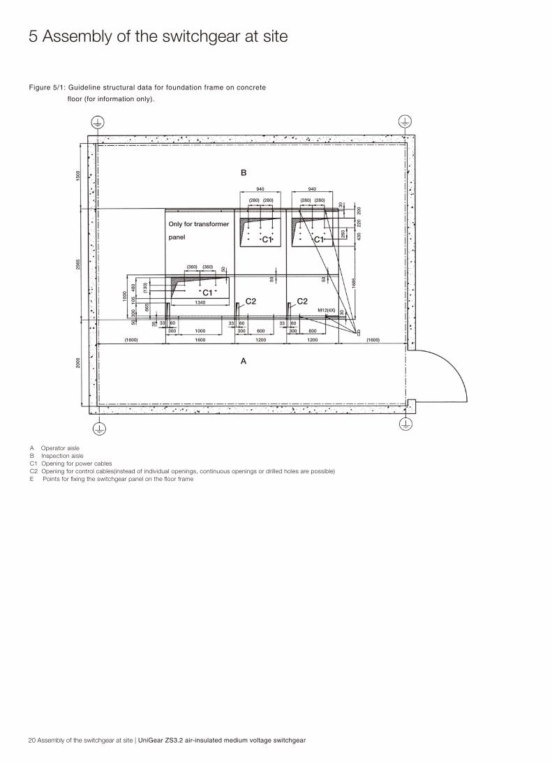
A Operator aisleB Inspection aisleC1 Opening for power cablesC2 Opening for control cables(instead of individual openings, continuous openings or drilled holes are possible)E Points for fixing the switchgear panel on the floor frame
Figure 5/1: Guideline structural data for foundation frame on concrete
floor (for information only).
1500
200
220
430
16855050
50
(360)(360)
Only for transformer
panel
(1600) (1600)1600 1200 1200
6006001000
1340
300
6033
300300
3333 6060
M12(4X)
355030
010
548
0
(130
)
1000
665
3026
030
940 940
(280) (280) (280) (280)
B
A
C1
C1 C1
C2 C2
2565
2000
5 Assembly of the switchgear at site

UniGear ZS3.2 air-insulated medium voltage switchgear | Assembly of the switchgear at site 21
1) Minimum dimensions1 Operator aisle2 Inspection aisle3 Opening for control cables (instead of individual openings, continuous openings or drilled holes are possible)5 Openings for power cables7 Panel type UniGear ZS3.2 ...31.5 kA
8 Power cables9 Projecting of floor frame: 5-12 mm above finished floor level10 Conductor to main earthing bar11 Screen 50 mm to 60 mm12 Hight of the cable cellar, to be determined by the client14 Guiding ramp, optional (recommended for circuit-breaker insertion)
1500
>40
00
2400
(78)
11 12
2565
7
(820)
(130)(130)
2
9
5 83 14
50200
10
1732 650300 2085
1000 35
1
2000
Ceiling
Circuit breaker

22 Assembly of the switchgear at site | UniGear ZS3.2 air-insulated medium voltage switchgear
Figure 5/4: For bolting the UniGear ZS3.2 panels together, threaded brushings are
provided at the right side near to the front and rear edges of the side
walls. Adequate bors are located at the left hand side of the panel
Figure 5/5: View into cable connection compartment max. 4 parallel cables possible
Figure 5/6: Partial view into the cable connection compartment prepared for connection
of two parallel cables
Figure 5/7: View into the busbar compartment
1.3 Aperture for main earthing bar1.5 Lifting lug(1.9) Threaded bushing, for switchgear assembly1.10 Bores (bushings), for switchgear assembly1.11 Cut-out for control wiring bushing28 Bushing plate
3.1 Tee-off conductor, busbar side3.11 Busbar section20.1 Spout, above
3.11
3.1
20.1
1.11
(1.9)
1.10
1.5
28
1.3
Figure 5/4
Figure 5/6 Figure 5/7
Figure 5/5
5 Assembly of the switchgear at site

UniGear ZS3.2 air-insulated medium voltage switchgear | Assembly of the switchgear at site 23
3 Busbar3.1 Tee-off conductor, busbar side25.5 Sealing ring28 Bushing plate29 Busbar bushing29.2 Busbar mounting for double conductor84 Partitioning
Figure 5/8: Bushings with busbar mountings for busbar system with double
D-profile, tee-off ...1600 A.
Figure 5/9: Bushings with busbar mountings for busbar system with double
D-profile, tee-off ...2000 A to 3150 A.
Figure 5/8 Figure 5/9

24 Assembly of the switchgear at site | UniGear ZS3.2 air-insulated medium voltage switchgear
Figure 5/10: Single rectangular copper busbar with single branch bar system
(...1600 A)
8.3 Contact spring (for rectangle busbar)8.4 Socket head bolt M6x168.5 Dished washer DIN 67968.6 Nut M68.7 Busbar mounting for single conductor
8.3 8.4,8.5,8.6 8.7
8.7
8.3
5 Assembly of the switchgear at site

UniGear ZS3.2 air-insulated medium voltage switchgear | Assembly of the switchgear at site 25
a) Detail of a busbar bushing, sectional view. Always check that there is proper contact between the metal tube in the bushing and the busbar via the contact spring.3.12 Busbar section (length)29.1 Busbar mounting for single conductor29.2 Busbar mounting for double conductor29.3 Contact spring29.4 Metal tube
The shrink-on sleeves must becut-out above the bores in thebusbars. The bores are requiredfor the inset of the contact spring 29.3.
b) Installation position of the phase barriers, viewed from top.28 Bushing plates29 Busbar bushing
Caution:The contact arm springs 29.3 or 8.3 must be inserted during the installation of the busbars. These contact springs prevent damages by glow discharges inside the bushings on Live busbars.
Figure 5/14: Busbar barriers
29.2 29.4 29.3 3.12

26 Assembly of the switchgear at site | UniGear ZS3.2 air-insulated medium voltage switchgear
During assembly, cut out the insulation cover and lid to fit cross-section of the feed-er or busbar.
3 Busbar3.1 Tee-off conductor3.5 Spacer plate, 15 mm3.6 Spacer plate, 10 mm58 Insulation cover58.5 Lid of cover163 M10 socket head bolt164 M10 nut165 10 mm dished washer
a) Arrangement for 1600 A tee-off current and 1600 A busbar current.b) Arrangement for 1600 A tee-off current and 2000 A or 3150 A busbar current.
3 Busbar3.1 Tee-off conductor3.5 Spacer plate, 15 mm3.6 Spacer plate, 10 mm29 Busbar bushing58 Insulation cover58.5 Lid of cover163 M10 socket head bolt164 M10 nut165 10 mm dished washer
a) Arrangement for tee-off current up to 1600 A and 1600 A or 3150 A busbar current.
Figure 5/15: Arrangement and bolting of single and double conductor busbars with
single and double tee-off bars. Ensure that screws and accessories
of the specified quality are used! Use 2 dished washers per screw
Figure 5/16: Arrangement of the busbar and tee-off conductor at the busbar end
Figure 5/15
Figure 5/16
5 Assembly of the switchgear at site

UniGear ZS3.2 air-insulated medium voltage switchgear | Assembly of the switchgear at site 27
Figure 5/17: Insulating covers for busbars | Figure 5/18: Guiding ramp for
circuit-breaker insertion, optional. The rail on the guiding ramp
must be in line with the guiding rail in the UniGear ZS3.2 panel
Figure 5/18
58.5 Lid for cover
Figure 5/17

Note on safety at workThe relevant work and operating procedures are to be carried out carefully by trained specialists familiar with the installation, taking into account all the relevant safety regulations to DIN VDE/IEC and the other relevant professional bodies, and other local and works regulations and instructions.
Note:Do not walk on the top surfaces of the switchgear panels (rupture points for pressure relief).
6.1 Commissioning6.1.1 Preparatory work(Figures 3/2, 3/15, 6/1 to 6/7)In preparation for commissioning, the following work should be carried out prior to connection with the high-voltage power supply:■ Check the general condition of the switchgear for detrimen-
tal circumstances of all kinds■ Perform a visual examination of the switching devices, with-
drawable parts, isolating contacts, insulating parts, etc■ Check the connection of the main earthing bar to the station
earthing conductor■ Check the paintwork for damage and touch up as described
in section 7.3 where necessary■ Remove all material residues, foreign bodies and tools from
the switchgear■ Clean the switchgear, rubbing down insulating parts with
a clean, soft, non-fraying and dry cloth. Remove greasy or adhesive dirt as described in section 7.2
■ Properly refit all covers etc. removed during as sembly and testing processes
■ Perform on site power frequency voltage testing of the main circuits to IEC 62271-200 as far as necessary. Pay special attention during this procedure to voltage trans formers and cables, etc
■ Switch on the auxiliary and control voltage■ Carry out test operations of switching devices manually or
by electrical control, and simultaneously observe the rele-vant position indicators
■ Check mechanical and electrical interlocks for effectiveness, without using force
■ Set the protective devices in the switchgear to the required values and check their function with test equipment
■ Instruct the local operators in the fundamental details of reg-ular handling of the switchgear
■ Check the readiness for operation and switching status of electrical systems upstream and down stream from the switchgear
■ Display the instruction manual in a position accessible to the operator at any time
Depending on the allocation of responsibilities, it may also be necessary to check the following equipment in areas adjacent to the switchgear:■ power cables■ auxiliary cables■ auxiliary power source and its polarity■ remote control system■ complete earthing system■ switch room equipment■ switch room condition
6.1.2 Start-up■ Comply with all relevant safety regulations■ Ensure that the circuit-breakers in the system are in the OFF
position■ Remove any existing earthing and short-circuiting connec-
tions in the critical switching area■ Energize the feeder cables■ Connect the switchgear step by step, observing the signals
and indicators■ Check that the relevant conductors are in phase, as far as
necessary when several incoming feeder cables and switch-gear sections are concerned (see also section 6.3.2)
■ Carry out all measurements and check all functions dependent on the high-voltage power supply being connected
■ Watch out for irregularities of any kind
6.2 Switching operations
Carry out switching operations with the panel doors closed.
6.2.1 Withdrawable circuit-breaker part(Figures 3/2, 6/1 to 6/7)
Manual insertion from the test/disconnected position to the service position:■ Connect control wiring plug 10.2■ Close the front door■ Ensure that the circuit-breaker is in the OFF position■ Fit hand crank 146 on square spigot 52.1 of the spindle
mechanism 52■ Turn the crank clockwise through approx. 45 turns until the
stop is reached and the withdrawable part is in the service position
■ Observe the position indicator■ Remove hand crank 146
Note:The withdrawable part must not be stopped at any position in the travel range between the service position and test/discon-nected position!
6 Operation of the switchgear
28 Operation of the switchgear | UniGear ZS3.2 air-insulated medium voltage switchgear

Manual withdrawal from the service position into the test/dis-connected position:■ Ensure that the circuit-breaker is in the OFF position■ Reverse the procedure described above for in sertion into
the service position
Note:Do not use force to move withdrawable parts with blocking magnet Y0 in the event of a voltage drop. If this occurs they are blocked along the whole travel range between the service position and test position. To remove the interlock, consult section 7.4.2.
Withdrawal from the test/disconnection position into the re-moved position:■ Open the door of the circuit-breaker compartment■ Release control wiring plug 10.2 and engage it in the storage
position on the withdrawable part■ Deblock the interlock yoke by moving the sliding handle 51.2
inwards against the springs to release the withdrawable part 50■ Move the withdrawable part out of the panel■ Close the panel door
Insertion from the removed position into the test/ disconnect-ed position:■ Carry out the procedure as described above for withdrawal,
changing the order accordingly■ When the switchgear is in operation, observe all the operat-
ing data and condition indications in the secondary area and watch for any irregulatities
6.2.2 Circuit breaker(Figures 6/1 to 6/5)For operation refer to Manual BA 483/02E, VD4, vacuum circuit breaker on withdrawable part or 1YHA000046-en, HD4 SF6 circuit breaker.
6.2.3 Earthing switch(Figures 3/2, 6/7 to 6/12)For operation refer also to instruction manual 1YHA000063-en, EK6 earthing switch.
The earthing switch type EK6 has a snap-action closing mechanism which is independent of the rotation of the drive shaft. The earthing switch type EK6 is only enabled for switch-ing when the withdrawable part 50 is in the test/disconnected position or removed from the switchgear panel. Only switch earthing switches on when the doors are closed. Only open the rear doors of the panel when the earthing switch is closed.
Opening and closing:■ Press slide 14.2 on the operating lever recess socket down
(When the switch is closed, it is already in this position!)■ Fit operating lever 122 to hexagonal shaft 14.1, which is
now released for operation
Note:Fit operating lever 122 to the hexagon shaft poin-ting either upwards or downwards for each swit-ching operation in such a way that it is not obstructed at the sides, even in limited space.
■ Turn the lever clockwise through approx. 180° until the stop is reached to close the earthing switch, or anti-clockwise until the stop is reached to open the earthing switch
■ Observe the mechanical/electrical switch position indicator■ Remove operating lever 122. Slide 14.2 remains open if the
earthing switch is in the closed position
Make sure that the operating lever is turned right up to the stop in the opening process, to ensure that the earthing switch is in its defined limit position.
The operating mechanism can also be fitted with a blocking magnet.
6.3 Test procedures6.3.1 Testing the off-circuit conditionThe panels can be fitted with a capacitive voltage indication system including the corresponding (hand-held) plug-in indica-tor for testing of the off-circuit condition.
A distinction must be made between the low impedance sys-tem and the high impedance system. For further details, see draft standard IEC 61243 Part 5.
The two systems differ in several respects, including different voltage levels which constitute the display thresholds. The capacitive voltage dividers installed in the panels are corre-spondingly of different ratings, and the measuring point sock-ets and indicator units are of different types.
Note:The only permissible indicators are those which satisfy the requirements of the IEC standards and corre-spond to the technical design of the indication system in the relevant switchgear!
Note:The measuring point sockets must on no account be short-cir-cuited, except for voltage tests on the installation (e.g. at power frequency voltage and/or impulse voltage).
Testing for the off-circuit condition is effected using a plugin indicator at the corresponding socket pairs located among the controls on the panels.
Use of the indicator:
UniGear ZS3.2 air-insulated medium voltage switchgear | Operation of the switchgear 29

30 Operation of the switchgear | UniGear ZS3.2 air-insulated medium voltage switchgear
■ Carry out a functional test on the unit immediately before use, e.g. with interface tester KSP. The display must be clearly perceptible
■ The presence of operating voltage is displayed by a signal
Always follow the details given in the instructions for the par-ticular indicator for your switchgear system.
Interface testing:■ Perform an interface test as a functional test on all coupling
components, e.g. with interface tester KSP■ The interface test is a repeat test as specified in IEC 61243
Part 5
Always follow the details given in the instructions for the par-ticular indicator for your switchgear system.
6.3.2 Testing of in-phase conditionTesting of the in-phase condition, e.g. when there is more than one incoming feeder, can be carried out with a suitable phase comparator coupled to the measuring point sockets of the capacitive voltage indication system (if fitted).
Test procedure:
■ Only use phase comparators which comply with the DIN VDE standards and are of suitable design for the switchgear system
■ Check the function of the unit immediately prior to use■ Ensure that the maximum permissible length of the measur-
ing cables for each phase is not exceeded■ Connect the measuring cables to precisely the correspond-
ing main conductor sections■ Follow the directions for the phase comparator in detail
After commissioning of the system, check all posi-tion indica-tors and displays for irregularities.
Note:For voltage testing at power frequency and/or impulse volt-age:■ Only short-circuit the sockets for the capacitive voltage indi-
cator on the relevant panel for the duration of the test
Caution:Operate truck slowly, be careful overturning Caused by inertia of fast movement!
50.4 Guide cam50.6 Front cover plate, right hand side50.7 Front coverplate, left hand side51 nterlock yoke51.1 Catch pin spring loaded51.2 Sliding handle
52 Spindle54.1 Link rod55.4 Switch position indicator55.5 Operating cycle counter55.6 Socket for charging lever55.7 Rating plate
55.6 Socket for charging lever55.8 Charging condition indicator128 Charging lever
Figure 6/1: Withdrawable part with circuit-breaker, VD4, operating mechanism side
Figure 6/2: Charging the spring energy storage mechanism manually by moving the inserted lever up and down
Figure 6/1 Figure 6/2
51.1 51.2 51 52 54.1
50.4 50.7 55.7 55.4 55.5 50.6
55.8
55.6
128
6 Operation of the switchgear

52 Spindle52.1 Square spigot146 Hand cranck
146 52.1 52
54 ON-OFF operating shaft145 Three bit key (ON-OFF operation)
54 145
Figure 6/3: Fitting the hand cranck (against spring-loaded intermediate plate) to move the truck inside the panel clockwise towards the service position, and anti-clockwise from the service position towards the test/disconnected position.Figure 6/4: Manual operation of the circuit-breaker, by turning the double bit key approx. 15° clockwise (ON), or approx. 15° anti-clockwise (OFF)Figure 6/5: Interlock yoke with sliding handles which will be moved inwards to release the circuit-breaker part for withdraw from the panelFigure 6/6: Withdrawable part in service position, interlock yoke engaged, control wiring pluged-in and engaged.Figure 6/3
51 Interlock yoke51.1 Catch pin, spring loaded51.2 Sliding handle51.4 Blocking shaft (interlocking circuit-breaker and earthing switch)
51
51.2
51.4
51.1
Figure 6/5
Figure 6/4
10 Control wiring plug connector, closed10.1 Control wiring socket10.2 Control wiring plug10.4 S8 /Limit switch for test position indicator10.5 S9 /Limit switch for service position indicator51 Interlock yoke51.3 Guide rail (panel)54 ON-OFF operating shaft
51.3 10.4 10.5
54
51
1010.110.2
Figure 6/6
UniGear ZS3.2 air-insulated medium voltage switchgear | Operation of the switchgear 31
32 Operation of the switchgear | UniGear ZS3.2 air-insulated medium voltage switchgear
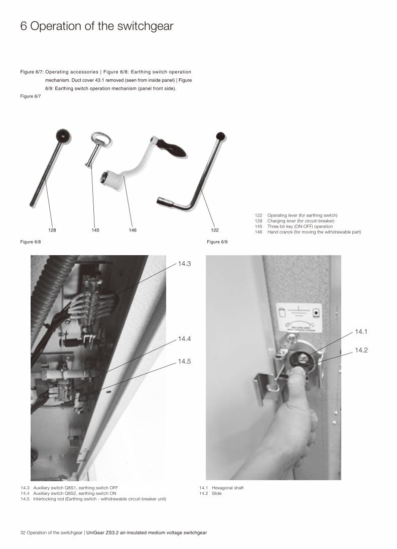
122 Operating lever (for earthing switch)128 Charging lever (for circuit-breaker)145 Three bit key (ON-OFF) operation146 Hand cranck (for moving the withdrawable part)128 145 146 122
Figure 6/7: Operating accessories | Figure 6/8: Earthing switch operation
mechanism. Duct cover 43.1 removed (seen from inside panel) | Figure
6/9: Earthing switch operation mechanism (panel front side).
14.3 Auxiliary switch Q8S1, earthing switch OFF14.4 Auxiliary switch Q8S2, earthing switch ON14.5 Interlocking rod (Earthing switch - withdrawable circuit-breaker unit)
14.1 Hexagonal shaft14.2 Slide
14.3
14.4
14.5
14.1
14.2
Figure 6/7
Figure 6/8 Figure 6/9
6 Operation of the switchgear

6.1
6.36.4
6.7
6.6
14.1
6.10
5
5 Insulated separating plate6.1 Bearing bracket6.3 Short circuit bridge6.4 Pair of earthing blades6.6 Bevel gear mechanism (not belonging to the earthing switch)6.7 Operating shaft6.10 Fixed earthing contact14.1 Hexagonal shaft
6.4 Pair of earthing blades6.5 Earthing conductor6.2 Toggle spring6.10 Fixed earthing contact14.1 Hexagonal shaft58 Insulation cover
58
6.10
6.4
14.1
6.2
6.5
6.1 Bearing bracket6.5 Earthing conductor6.6 Bevel gear mechanism (not belonging to the earthing switch)6.7 Operating shaft6.8 Driver lever14.1 Hexagonal shaft
6.1
6.5
6.76.6
6.8
14.1
Figure 6/10: Active part of the earthing switch, EK6 mounted in the cable connection
compartment shown in open position
Figure 6/11: Earthing switch, EK6 mounted in the cable connection compartment
shown in closed position
Figure 6/12: Bevel gear mechanism and earthing switch, EK6 in open position
Figure 6/10
Figure 6/11
Figure 6/12
UniGear ZS3.2 air-insulated medium voltage switchgear | Operation of the switchgear 33

34 Maintenance | UniGear ZS3.2 air-insulated medium voltage switchgear
7.1 GeneralMaintenance serves to preserve trouble-free operation and achieve the longest possible working life of the switchgear. In accordance with DIN 31 051, it comprises the following close-ly related activities:
Inspection: Determination of the actual conditionServicing: Measures to preserve the specified conditionRepair: Measures to restore the specified condition
Note:When carrying out all maintenance work, the regulations in the country of installation must be strictly complied with.
Maintenance work may only be performed in a careful manner by trained personnel familiar with the characteristics of the individual switchgear, in accordance with all relevant safety regulations to VDE/IEC and of other technical authorities, and with other overriding instructions. It is recommended that ABB service personnel be called in to perform servicing and repair work, and this is necessary for some of the work detailed be-low.
The inspection and servicing intervals for some of the equip-ment/components (e.g. parts subject to wear) are determined by fixed criteria such as switching frequency, length of service and number of short-circuit breaking operations. For oth-er parts, on the other hand, the length of the intervals may depend, for example, on the different modes of operation in individual cases, the degree of loading, and also environmen-tal influences (including pollution and aggressive air).
The following service instructions must also be observed together with this instruction manual in the individual cases concerned:
Vacuum circuit breakerVD4 BA 483/02ESF6 circuit breakerHD4 1YHA000046-enEarthing switchEK6 1YHA000063-en
If necessary, further details can be taken from the technical documentation for the switchgear instal-lation (including, for example, any agreed special service conditions).
7.2 Inspection and servicingInspectionInspection of the switchgear should be carried out approx-imately every two to four years, depending on the service conditions and local environment, in accordance with VBG4 standard.
Isolate the area where work is to be performed in accordance
with the relevant safety regulations to DIN VDE/IEC, and se-cure it against reconnection.
The inspection may become necessary at shorter intervals under unusual service conditions (including advers climatic conditions) and/or particularly injurious environmental influenc-es (e.g. heavy pollution and aggressive atmosphere).The inspection should include but not be limited to the follow-ing:
■ Check the installation for abnormalities of any kind, dirt and the effects of other environmental influences
■ Check the function of the switching devices and the con-trols, interlocks, protection, annunciation and other devices
■ Check the surface condition of the isolating contact system (for visual examination of the contact pins with the with-drawable part removed). When the galvanic silver coating on the contact parts is worn to such an extent that the copper conductor material below becomes visible, or when their surfaces are heavily corroded or show signs of other damage or overheating (discoloured surface), replace the contact parts. See also section 7.3
■ Check all switchgear accessories and the auxiliary equip-ment (e.g. storage batteries etc.)
■ No external discharge may occur on the surfaces of equip-ment at operating voltage. This can, for example, be detect-ed by characteristic noises, a clearly perceptible smell of ozone, or visible glowing in the dark
ServicingBasic servicing activities, and those which may be found nec-essary during inspections, include the following:
■ Carefully clean the unit, and in particular the insulating material surfaces, when they are found to be dirty (con-tamination may also be caused by salt, mould formations, insects or conductive materials in conjunction with frequent conden-sation when the switchgear is operated in a tropical climate). Remove dry dust deposits which do not adhere strongly using a soft dry cloth. Re move more strongly adhering, e.g. sticky/ greasy dirt, with a cloth soaked in a slightly alka-line household cleaner. Wipe off with clear wa-ter and dry carefully
Use halogen-free cleaners such as Rivolta BWR 210 or cold cleanser 716 (for components in insulating material and for major contamination). Observe the manufacturer’s instruc-tions and the special ABB instruction manuals BA 1002E and BA 1006E respectively on safety at work.Never use 1.1.1-trichloroethane, trichloroethy-lene or car-
7 Maintenance

bon tetrachloride!
■ Should external discharges occur as a result of conden-sation, application of a thin silicone film on the surface concerned is often effective as a temporary remedy. It is advisable to request advice from the ABB after-sales service department on permanent solutions to such unusual prob-lems
■ Check that the bolt connections at the contact points in the busbar system and the earth connections are tight, and that the isolating contact system functions correctly
■ Regrease the contact points and mechanism of the with-drawable part insertion system as necessary, or, when lubri-cation is inadequate or missing, thoroughly clean the areas concerned and regrease with Isoflex Topas NB52 lubricant
■ Top up the grease on sliding and bearing surfaces in the panels - for example on the separating plates, the interlock and guide systems, the spindle mechanism and the travel rollers of the withdrawable part - or thoroughly clean and regrease with Isoflex Topas NB52 lubricant where necessary
■ Observe the maintenance instructions in the manuals for the individual switch types
7.3 Repair7.3.1 Switchgear surface■ Carry out repair work immediately after a defect has been
discovered
■ Completely remove all rust from damaged paintwork areas on steel sheet and other steel parts by mechanical means, e.g. with a wire brush
Lightly grind the surrounding paint coat and carefully degrease the entire area. Then immediately apply an an-ti-rust primer and, after an appropriate hardening time, apply the top coat. The total dry film thickness should be approx. 60 µm. Only use suitable and compatible paint products
Top coat in standard colour RAL 7035 or the relevant spe-cial colour
■ Carefully remove any white rust from Al-Zn sheet steel surfaces with a wire brush or Scotch Sprite, and remove loosely adhering particles with a dry, non-fraying cloth. Then treat the cleaned areas with zinc spray or zinc dust paint, and then with aluminium spray to match up the colour
■ Carefully remove any white rust on chromium plated func-tional parts and rust on phosphatized parts with a wire brush or Scotch Sprite, and clean with a dry cloth. Then evenly grease the parts (with Isoflex Topas NB52)
7.3.2 Replacement of componentsReplacement of the isolating contact systems: (Figures 7/1 to 7/4)■ Slide the two inner annular tension springs 57.6 facing the
breaker pole to a position beside the two outer annular tension springs, thus releasing contact system 57.7, and remove the contact sys tem from isolating contact arm 57.1/57.2
■ Fit a new contact system back to front on the thin end of arbor 127, and slide it forwards onto the thicker part of the shank
■ Fit arbor 127 onto the relevant contact arm 57.1/ 57.2, slide the contact system 57.3 over onto the isolating contact arm, and withdraw the arbor
■ Check all contact fingers and annular tension springs for perfect fit
Note:The set installation position of isolating contact arms 57.1/57.2 must not be changed by the improper use of force.
Replacement of the contact pins:(Figure 3/13, 3/17 and 3/18)After any required replacement of contact pins 25.1/25.2, these are to be retightened using socket head screws:■ Thread M10, non-greased, at 50 Nm■ Thread M12, non-greased, at 86 Nm■ Thread M20, non-greased, at 200 Nm
7.4 Tests on withdrawable parts with circuit-breakers of VD4 or HD4(Figures 3/12, 3/14, 3/15, 6/1 to 6/7)When functional tests are carried out on withdrawable parts, compliance with the conditions listed below should also be checked.
7.4.1 Checking the auxiliary switch settings on withdrawable parts(Figures 6/3 to 6/6)Refer to manual BA 483/02E; VD4, vacuum circuit-breaker on withdrawable part or HD4 SF6 circuit breaker 1YHA000046-en.
Compliance with the interlock conditions in the areas of the test/disconnected position and the service position is ensured by position signalling switches 10.4 (S8) and 10.5 (S9) located on the withdrawable part and set at the works.
UniGear ZS3.2 air-insulated medium voltage switchgear | Maintenance 35

36 Maintenance | UniGear ZS3.2 air-insulated medium voltage switchgear
In the inspection and test operation, the withdrawable part is to be moved with the crank fitted.
1. Settings in the area of the test/disconnected position■ Move the withdrawable part out of the test/disconnected
position towards the service position with a few turns of the crank
■ Slowly move the withdrawable part back to the stop
Auxiliary switch 10.4 (S8) must then operate when the hand crank still has ≥ 60° of turn to reach the stop.
■ Slowly insert the withdrawable part from the test/discon-nected position towards the service position until auxiliary switch 10.4 (S8) just operates
In this position, it must still just be possible to move the ON-OFF operating shaft 54. For this test, the function of the blocking magnet must be deactivated manually.
This condition ensures that the electrical interlock becomes active before the mechanical interlock in the motion sequence involved.
2. Settings in the area of the service position■ Move the withdrawable part out of the limit position towards
the test/disconnected position with a few turns of the crank
■ Slowly move the withdrawable part forwards again up to the stop
Auxiliary switch 10.5 (S9) must then operate when the hand crank has a remaining angle of ≥60° to turn up to the stop.
7.4.2 Testing of interlock conditions(Figures 6/1 to 6/9)1. The withdrawable part must only be movable from the test/ disconnected position into the ser vice position when the circuit-breaker is open and the earthing switch is open.
Check the following conditions individually:■ With the circuit-breaker closed, insertion of the withdrawable
part towards the service position must be blocked after only half a turn of the crank in the clockwise direction
■ With the earthing switch closed, insertion of the with-drawable part towards the service position must be blocked after only two clockwise turns of the crank
2. The withdrawable part must only be movable from the ser vice position into the test/disconnected position with the circuit-breaker open.
Check this condition as follows:■ With the circuit-breaker closed, withdrawal movement of the
withdrawable part must be blocked after only half a turn of the crank in the anti-clockwise direction
3. Closing of the circuit-breaker must only be possible when the withdrawable part is in the defined test/disconnected position or service position.
The control wiring plug 10.2 must previously have been insert-ed.
Check this condition as follows:■ It must not be possible to close the circuitbreaker with the
withdrawable part in any position between the test/discon-nected position and the service position
Enabling of switching when the withdrawable part moves into the service position is effected electrically by operation of auxiliary switch 10.5 (S9), and mechanically slightly earlier; the latter corresponds to a position approximately half a turn of the crank before the stop.
■ The enable conditions for the movement into the test/dis-connected position apply accor-dingly, in this case estab-lished by auxiliary switch 10.4 (S8)
4. It must only be possible to open the circuit-breaker (manually) when the withdrawable part is in the service position or test/ disconnected position and the control voltage has failed.
Check this condition.
5. The withdrawable part with blocking magnet Y0 (if ordered) may not be moved if the control voltage fails or is not avail able. Do not use force to move the blocked withdrawable part!
Removing the block:■ Remove front plate 50.6 and 50.7
■ Release the blocking magnet Y0 by pressing the armature continuously when moving the withdrawable part by using the hand crank 146 for 1/2 right or left
■ The blocking magnet is effective only in the service and test/disconnected position and is not effective in the intermedi-ate position
6. Removal of control wiring plug 10.2 and reinser tion of the plug must be blocked with the with drawable part in the service position.
Check this condition.
7. Operation of the earthing switch must only be possible when withdrawable part 50 is in the test/ disconnected position or the removed position (subject to any additional electromag- netic inter locks in individual cases!).
7 Maintenance

Check these conditions as follows:■ With the withdrawable part in the test/ disconnected posi-
tion, it must be possible to press slide 14.2 in front of the earthing switch drive shaft 14.1 downwards to the opening position. The earthing switch can then be operated
■ When the withdrawable part is moved inwards towards the service position, pressing down of the slide 14.2 must be blocked after only one and a half clockwise turns on the crank
7.5 Tests on the switchgear panel7.5.1 Auxiliary switch setting on the earthing switch (Figures 6/8 and 6/9)1. There must be a run-on of 0.5 mm in the fully operated position before the plunger reaches the stop (for safety reasons).
2. Limit position auxiliary switch Q8S2 for earthing switch ON must be operated immediately after the dead centre posi- tion of the toggle spring mechanism is reached in the closing process and the automatic quick-closing process has started.
3. Limit position auxiliary switch Q8S1 for earthing switch OFF must be operated on earthing switches with manual mech anisms during the opening motion of the slide 14.2 before half of the hexagon shaft has become visible, or 1 mm be- fore the tongue of the slide makes contact with the arma- ture of the unexcited blocking magnet.
7.6 Spare parts, auxiliary materials and lubricants7.6.1 Spare partsA spare parts list is available on request for procure-ment of spare parts. It fundamentally comprises moving parts and parts subject to wear. When parts are required, the serial numbers of the relevant switchgear panel and circuit-breaker should always be quoted.
7.6.2 Auxiliary materials and Part no.lubricants (order ref.)Lubricant:■ Isoflex Topas NB52 GCE0007249P0100 Halogen-free cleansers:■ Rivolta BWR 210 GCE0007707P0100 (for general cleaning) ABB directions for use BA 1002/E GCEA901002P0102■ Cold cleanser 716 GCE0007706P0100 (use for conductive components, compon-ents in insulating material and for heavy soiling) ABB directions for use BA 1006/E GCEA901006P0102Touch-up paint:■ Standard colour RAL 7035 ■ 1-kg-box GCE9014060R0103 ■ 1 Spray tin GCE0007895P0100

57.13 Contact system, 2000 A to 3150 A57.6 Internal annular tension springs57.7 External annular tension springs130 Auxiliar arbour, 2000 A to 3150 A130.1 Plug, 2000 A to 3150 A
130.1 130 57.13 57.6 57.7
Figure 7/3 Figure 7/4
1> left: front view2> right: rear view
57.3 Contact system, ...1600 A127 Auxiliary arbour, ...1600 A127.1 Plug, ...1600 A
127.11 2
127 57.3
Figure 7/1 Figure 7/2
38 Maintenance | UniGear ZS3.2 air-insulated medium voltage switchgear
7 Maintenance
Figure 7/1: Contact system sample for 2000 A to 3150 A | Figure 7/2: Sliding
the contact system onto the auxiliary arbour with the rear end first,
schematic representation here for 1600 A | Figure 7/3: Contact shift
on auxiliary arbour for 2000 A to 3150 A
Figure 7/4: Sliding of the contact system from the auxiliary arbour onto the
contact arm and engaging it here

8 Product quality and environmental protection
UniGear ZS3.2 air-insulated medium voltage switchgear | Product quality and environmental protection 39

Contact us
ABB Xiamen Switchgear Co., Ltd.ABB Industrial Park, Torch High-Tech Zone, No. 319,Xiamen, Fujian, P.R.ChinaTel: +86 592 602 6033Fax: +86 592 603 0505Zip code: 361006Service hotline: 800-820-9696 400-820-9696
www.abb.com.cn/mv
We reserve the right to make changes in the course of technical development. G
.


![Unigear Ma_en 1vlm000363 Rev[1].g](https://static.fdocuments.in/doc/165x107/551fa676497959335b8b50af/unigear-maen-1vlm000363-rev1g.jpg)


