
INSTRUCCIONESDEARMADO - c.searspartsdirect.com · 17. Slide the Support Tube (#2) through the...
19
INSTRUCCIONES DEARMADO Do Not Return This Product To The Store Toll Free: 877-885-1635 www.medalsports.com .tw No devuelva este producto a su local de venta N0mero telef6nico gratis: 877-885-1635 www.medalsports.com .tw MODEUMODELO: 57000
Transcript of INSTRUCCIONESDEARMADO - c.searspartsdirect.com · 17. Slide the Support Tube (#2) through the...

INSTRUCCIONESDEARMADO
Do Not Return This Product To The StoreToll Free: 877-885-1635
www.medalsports.com .tw
No devuelva este producto a su local de ventaN0mero telef6nico gratis: 877-885-1635www.medalsports.com .tw
MODEUMODELO: 57000

This product is covered by a limited warranty that is effective for
90 days from the date of purchase. The warranty covers any
defects in parts and workmanship.
If, during the limited warranty period, a part is found to be defective
or breaks, we will offer either a free repair or replacement part at no
cost to you, the customer. The only exceptions to the warranty incl-
ude main frames, table tops, playing surfaces, batteries, tools. The
above warranty will not apply in cases of damages due to improper
usage, alteration, mis=use, abuse, accidental damage or neglect.
A PURCHASE RECEIPT (or other proof of purchase date) will be
required before any warranty service is initiated. All requests for
warranty service can be submitted by email, in writing or by con=
tacting our Consumer Service Dept. at:
Toll Free: 877-885-1635
Email: [email protected]: www.medalsports.com.tw
This Limited Warranty gives you specific legal rights and youmay also have other rights which vary from one state (province)to another.
PLEASE SAVE THESE INSTRUCTIONSAND PURCHASE RECEIPT!
DO NOT RETURN THIS PRODUCT TO THE STORE!

Please Keep Your Instructions! Your Model number is necessary should you need to contact
us. Please read through this instruction manual book to familiarize yourself with all parts and
assembly steps, kindly refer to the parts identifier below and be sure that all parts have beenincluded.
Although we are dedicated to giving our customers the best product possible, a question
may arise or parts may be missing. If you are missing parts, or, if you have any questions,
please contact our fast and friendly service centre on :877-885-7635
Phillips Screwdriver- Not IncludedStandard (Flat Head Screwdriver)- Not IncludedAllen Wrench - Included
Electric Screwdrivers may be helpful during assembly; however, please set a low
torque and use extreme caution because screws may be high. stripped or over-tightened if the electric screwdriver's torque is set too high.
1- When installing parts that have more than one bolt, hand tighten all bolts before
tightening individual bolts with a screwdriver or allen key.
2- Some figures or drawings may not look exactly like your product. Please read and
understand the text before beginning each assembly step.
OTICE!READ AND FOLLOW ALL ASSEMBLY, OPERATION, AND SAFETY INSTRUC-TIONS CAREFULLY. AT LEAST TWO ADULTS ARE NEEDED FOR THE ASSEMBLY
OF THIS TABLE.
THIS IS NOT A CHILD' S TOY. ADULT SUPERVISION IS REQUIRED FOR CHIL-DREN PLAYING THIS GAME. PLEASE READ INSTRUCTIONS CAREFULLY.PROPER USE OF THIS SET CAN AVOID DAMAGE OR INJURY.
WARNING" Adult Assembly Required. iWARNING"CHOKING HAZARD - - This item contains small parts.
Not suitable for children under 3 years.
2

PARTS iDENTiFiER
#1
U-Tube
1 Piece
#6
Side Brace2 Pieces
#11
Back-Upright Tube-C2 Pieces
#16
Electronic Scorer1 Piece
#21
M6X32MM Bolt
18 Pieces
#26
®M6 Locknut26 Pieces
#2
Support Tube-A3 Pieces
#7
"L" Support Tube2 Pieces
#12
I
Top Tube2 Pieces
#17 Pre-assembled
Rim Net1 Piece
#22
M6X20MM Bolt
8 Pieces
#27
Basketball2 Pieces
#3
#8
#13
#18
#23
"L" Base Tube
2 Pieces
Support Tube-B1 Piece
J
Backboard1 Piece
Ramp Net1 Piece
3.0X26MM
Wood Screw4 Pieces
Allen Key1 Piece
#4
Connect Tube
2 Pieces
#9
Back-Upright Tube-A2 Pieces
#14
Rim1 Piece
#19 Pre-assembled
#24
Lock Pin2 Pieces
12mm Fiat Washer
38 Pieces
#5
Base Tube
2 Pieces
#10
Back-Upright Tube-B2 Pieces
#15
#20
OO
Metal Spacer Plate1 Piece
#28 #29
Wrench1 Piece
M6X42MM Bolt4 Pieces
#25
Switch with
Paddle assembly1 Piece
#30
Inflation Pumpwith Needle
1 Piece
WARNING:1) Require 4pcs AA Batteries (Not included).
2) Do not mix old and new batteries.3) Do not mix alkaline, standard (carbon zinc), or rechargeable (nickel-cadmium) batteries.
3

ASSEMBLY iNSTRUCTiONS
1. Find a clean, level place to begin the assembly of your Basketball Game. We recommendthat two adults work together to assembly this basketball game.
2. Remove all the parts from the box and verify that you have all of the listed parts as shownon the parts identifier below. Carefully cut or tear the four corners of the box so that the
bottom of the box can be used as your work surface.
FIG. I
3. Connect the U-tube (#1) to L Base tubes (#3) by sliding them together and locking in theplace as shown in FIG.1 and 1A.
FIG. 2
#1 .......
_#3
_.. _pring Lock
Detail A
4. Connect Side Braces (#6) to Back-Upright Tubes-A (#9) by using one Bolt (#21) and oneWasher (#24) per side as shown in FIG.2.
_ ........ #21#24
FIG. 3
5. Connect one Support Tube-B (#6) to the tube assembly (#6 and #9) by using two Bolts (#21),
two Washers (#24) and two Locknuts (#26) per side as shown in FIG.3
Note: Make sure all the Bolts (#21) go from the outside toward the center.
J- #9
#26 #2,\\
#6
4

FIG. 4
6. Connect BaseTubes (#5) to the assembled Side Braces (#6) by using Bolts (#21) andWashers (#24) as shown in FIG.4.
#21 #24
FIG. 5
7. Connect Back-Upright tubes-B (#10) to assembled tubes (#9) by sliding them together and
locking in the place as shown in FIG. 5. Then, connect the Tubes (#11) to assembledtubes (#10) by sliding them together as shown in FIG.5.
8. Connect the upper sides of L Support Tubes (#7) and Support Tube-A(#2) to the tubeassembly (#11 and #10) by using two Bolts (#21), two Washers (#24) and two Locknuts
(#26) per side. Then, slide the lower sides of L Support Tubes (#7) to the assembled tubes(#5) together.
9. Connect the Support Tube-A (#2) to the assembled tubes (#7 and 5) by using Bolts (#21),Washers (#24) and Locknuts (#26).
Note: Make sure all the Bolts, Washers and Locknuts go from the same directionsas shown in FIG.5.
#7 --.
#21-.. _:
#26___" _ #2
#24 _
"#11
!
_#9
Spring Lock
5

FiG. 6
10. Connect the Connect Tubes (#4) to the front of assembled tubes (#5) by using
Bolts (#21), Washers (#24) and Locknuts (#26). Make sure Spring Lock mustface down before assembly as shown in FIG.6A.
#11
*Spring lock must face down.
#26
........#4 _-
#5
11 tl
FiG. 7
11. Connect the tube assembly (#1 and #3) to the assembled Connect Tubes (#4)and Spring Lock must be in the place as shown in FIG.7 and 7A.
#4
__Spring Lock
6

FiG. 8
12. Connect Top Tubes (#12) to the assembled tubes (#11) by sliding them together. Then,
slide the two sleeves of the Ramp Nets (#18) onto each Top Tubes (#12) as shown in FIG.8.
FIG. 9
13. Tear off the paper from in front of Electronic Scorer (#16) and stick it to the Backboard(#13). then using four Screws (#23) as shown in FIG.9A.
14. Attach the Rim (#14) to the Backboard (#13) using four Bolts (#22), the Metal SpacerPlate (#15) to the back of backboard, four Washers (#24) and four Locknuts (#26)as shown in FIG.9B.
15. Attach the Switch with Paddle assembly (#25) to the Backboard (#13) using four Bolts(#22), eight Washers (#24) and four Locknuts (#26) as shown in FIG. 9B.
16. Connect the wire coming from the Switch with Paddle assembly (#25) to the ElectronicScorer (#16) as shown in FIG. 9C.
#16
#13
o
o
o
#23
0
0 #16
#24
#25
0
#26
A_
\#24
7
#16

FiG. I 0
17. Slide the Support Tube (#2) through the sleeve on the front of the Ramp Net(#18) by usingone Bolt (#21), one Washer (#24) and one Locknut (#26) per side as shown in FIG.10A.
18. Attach the assembled Backboard (#13) to the upper tube assembly using four Bolts (#20),
eight Washers (#24) and four Locknuts (#26) as shown in FIG.10B.
#13
#24
#20
#2
#1

FiG. 11
19. For easy storage, this basketball game can be folded upright easily as shown in FIG.11.
20. Fold the end of ball return toward the backboard and insert the Lock Pin(#19) into theopening as shown in FIG.11.
#19
In playing mode use pin to fix ramp.
In storage mode use pin to fix ramp in folding position.
ELECTRONIC SCORER OPERATION
1. Unscrew bolt using a screwdriver and open the battery box. Insert 4 AAbatteries ( not included) in the order of polarity as shown on the inside
cover. Then close the cover using a screwdriver. Turn the power on usingthe on/off switch. (if the game will not be used for a long period of thetime, we recommend that the batteries should be removed). \
_ SOUND2. Sound ON/OFF - use this switch while the game is on to turn the sound ON/OFF
OFF and ON.
3. While game is in Sleep Mode, if a basketball is scored, the game will turn back on and the scoreboard will begin the 5 sec. countdown.
4. After finishing the game, Turn OFF the scorer by using the ON/OFF switch. NOTE: The scoreboard
will turn off after 5 minutes, if not in use, however, we recommend turning the ON/OFF switch toOFF when the game will not be used for an extended period of time.
This device complies with the part 15 of the FCC rules.Operation issubject to the following two conditions :
(1) This device maynot cause harmful interference, and(2) This device must acceptany interference received, including interference that may
causeundesired operation.

Este producto esta cubierto por una garantia efectiva de 90 dias apartir de la fecha de su compra. La garantia cubre cualquier defe=cto en las partes yen la obra del trabajo.
Durante el peri6do limite de la grantia, si una parte defectuosa oquiebrada es encontrada, nosotros ofreceremos una reparaciono un reemplazo de la parte sin ningOn costo para ud, nuestro cli=ente. La Onica excepcion que la garantia no fuera aplicada serialos da_os causado por un uso inapropiado, alteracion, uso equi=vocado, abuso, da_o accidentado o negligencia.
El RECIBO DE LA COMPRA (o cualquier otra prueba de la fechade su compra) seria requerida antes que cualquier servicio de g=arantia fuera iniciada. Cualquier requerimiento para el servicio dela garantia puede ser presentado por email, escrito o contactandoa nuestro Dept. de Servicio del Consumidor en :
N_mero telef6nico gratis: 877-885-1635Email: [email protected]: www.medalsports.com.tw
Esta garantia limitada le da a usted derechos legales especificos,usted tambien puede tenet otros derechos que varian de un esta=do (provincia) a otro/a.
POR FAVOR GUARDE ESTAS INSTRUCCIONESY RECIBO DE LA COMPRA !
NO DEVUELVA ESTE PRODUCTO A SU LOCAL DE VENTA!
10

iPor favor guarde las instrucdones. Esnecesado el nOmero de modelo para contactarse connosotros. Por favor I_a las instrucdones para poder familiarze con laspiezasy los pasos paraensamblar. Corrobore que todas las piezas que aparecen en el "ldentificador de Partes" se
encuentren en el paquete.
A pesar de que nos dedicamos a dar los mejores productos posibles para nuestros clientes,
pueden ocurdr problemas o faltar piezas. Si le faltan piezas 6 si tiene alguna inquietud, por
favor cont_ctenos Io antes posible a nuestro cordial centro de atenci6n: 877-885-1635
Destornillador Phillips - No incluidoDestornillador de Cabeza Plana - No incluido
Llave Allen - Incluido
Los destornilladores electricos pueden set de gran ayuda durante el ensamblado; sin
embargo, por favor ajuste el par de giro bajo y sea extremadamente precavido porquelas tuercas pueden ser barridas o sobreajustadas si el destornillador electrico esta
establecido muy alto.
1- Cuando se instalen partes con mas de un tornillo, ajOstelo manualmente primero
y luego con un atornillador o Llave Allen.
2- Algunos dibujos o figuras no se veran exactamente igual al producto. Pot favor
lea y comprenda el texto antes de empezar los pasos de ensamblado.
f
P ECAUClOLEA Y SIGA CUIDADOSAMENTE TODAS LAS INSTRUCCIONES DE ENSAMBLAJE,OPERACION Y SEGURIDAD. SE NECESITAN COMO MiNIMO DOS ADULTOS
FUERTES PARA EL MONTAJE DE ESTA MESA.
I=STE NO ES UN JUGUETE PARA NINOS. LA SUPERVISION ADULTA ES NECESARIA
DURANTE EL JUEGO CON NINOS. POR FAVOR LEA LAS INSTRUCCIONES CUI-
DADOSAMENTE. EL USO APROPIADO DEL JUEGO EVITARA DANOS O HERIDAS.
ADVERTENCIA: Las tareas de montaje debe realizarlas un adulto.
/!k ADVERTENCIA:PELIGRO DE ASFIXIO - - Este articulo contiene piezas peque_as.
No apto para menores de 3 aSos
11

|DENT|F|CADOR DE LAS PARTES
#1
Tubo-U
1 Pieza
#6
Abrazadera Lateral2 Piezas
#11
Tubo VerticalTrasero -C2 Piezas
#16
Marcador Electr6nico1 Pieza
#21
Perno M6X32MM
18 Piezas
#26
®Contratuerca M6
26 Piezas
#2
Tubo de soporte - A3 Piezas
#7
Tubo de Soporte "L"2 Piezas
#12
I
Tubo superior2 Piezas
#17 pre-montada
Red de Canasta1 Pieza
#22
Pemo M6X20MM
8 Piezas
#27
Baloncesto2 Piezas
Tubo de Base "L"
2 Piezas
#3
Tubo de Soporte -B1 Pieza
#8
.13//.
J
Tabtero de Ia Canasta1 Pieza
#18
Ned de Nampa1 Pieza
#23
Tornitlo de Madera
3.0X26MM4 Piezas
Tubo de Conecci6n
2 Piezas
#4
#9
Tubo VerticalTrasero -A
2 Piezas
#14
Canasta1 Pieza
#19 pre-montada
Ctavija de Btoqueo2 Piezas
#5
#10
#15
Tubo de Base
2 Piezas
#24
#20
Tubo VerticalTrasero -B2 Piezas
LLAVE ALLEN1 Pieza
Arandela Plana 12 mm
38 Piezas
OO
Placa Separadorametalica
#28 #29
LLAVE DE TUERCA1 Pieza
1 Pieza
Perno M6X42MM4 Piezas
#25
Interruptor con
Palanca pre-montada
1 Pieza
#30
BOMBA DE INFLACIONCON AGUJA
1 Pieza
PRECAUCION:1) 4 pilas AA no incluidas.2) No mezcle pilas nuevas con viejas.3) No mezcle pilas alcalinas, est_ndar (carbono zinc), o recargables (niquel cadmio).
12

|NSTRUCC|ONES PARA EL MONTAJE
1. Encuentre un lugar despejado y nivelado para empezar a montar su Juego de Baloncesto.Le recomendamos dos personas adultas para montar en conjunto a este juego de baloncesto.
2. Saque et contenido de la caja y vedfique que usted tiene todas las pares como se muestraen el identificador de partes. Le sugedmos que usted use la parte inferior de la caja como un
&tea detrabajo limpia y plana para proteger el juego. Corte cuidadosamente los lados de lacaja para quepueda usar la parte inferior como su superficie de trabajo.
FIG. I
3. Conecte el Tubo-U (#1) con el Tubo de Base L (#3) desliz&ndolos y cerrandolos en el lugarcomo indicado en FIG.1 y 1A
FIG. 2
#1 ......
_#3
Cerraduras
_,....._/D e Resorte
Detail A
4. Conecte las Abrazaderas Laterales (#6) al Tubo Vertical Trasero -A(#9) usando un Perno(#21) y una Arandela (#24) por cada lado, como se indica en FIG.2.
_ ........ #21#24
FIG. 3
5. Conecte un Tubo de Soporte -B (#8) al tubo montado (#6 y #9) usando dos Pemos (#21),
dos Arandelas (#24) y dos Contratuercas (#26) por cada lado como indicado en FIG.3
Nota:Aseg#rese que todos los Pernos(#21) van desde el lado exterior hacia el centro.
J_ #9
#26 #2\
#6
13

FiG. 4
6. Conecte los Tubos de Base (#5) al Abrazadera Lateral montado (#6) usando Pernos (#21) yArandelas (#24) como indicado en FIG.4.
#51 #24
FIG. 5
7. Conecte el Tubo Vertical Trasero -B.(#10) al tubo montado(#9) desliz&ndolos y cerrandolos
juntos en paso como indicado en FIG.5. Luego, conecte los Tubos (#11) a los Tubos montados(#10) desliz&ndolos junto como indicado en la FIG.5
8. Conecte las partes supedores de los Tubo de Soporte "L" (#7) y el Tubo de soporte - A (#2)Con el tubo montado (#11 y #10) usando dos Pemos (#21), dos Arandelas(#24) y dos
Contratuercas(#26) pot cada lado. Luego, deslice la parte inferior del Tubo de Soporte L (#7)junt&ndolo con los tubos montados (#5).
9. Conecte el Tubo de soporte - A (#2)a los tubos montados (#7 y 5) usando Pemos (#21),Arandelas (#24) y Contratuercas (#26).
Nota: Aseg_rese que todos los Pernos, Arandelas y Contratuercas van desde la mismadirecci6n como indicado en FIG.&
#7 --.
#21-.. _:
#26
#24 _
....#11
I
.....#10
!
.... #9
CerradurasDe Resorte
14

FIG. 6
10. Conecte los Tubos de Conecci6n (#4) adelante de los tubos montados (#5) usando Pernos
(#21), Arandelas (#24) y Contratuercas (#26). AsegQrese que antes de montar, la Cerradurade Resorte debe dirigir con su cara hacia abajo como indicado en FIG.6A.
#11
*La cerradura de/resorte debe
dirigirse con su tara hacia abajo.#5
#26
........#4 _-
11 tl
FIG, 7
11. Conecte el tubo montado (#1 y #3) a los Tubos montados que est&n conectado (#4) y laCerradura de Resorte debe ir en el lugar como Io indicado en FIG.7 y 7A.
#4
__CDr rRdeUrade
15
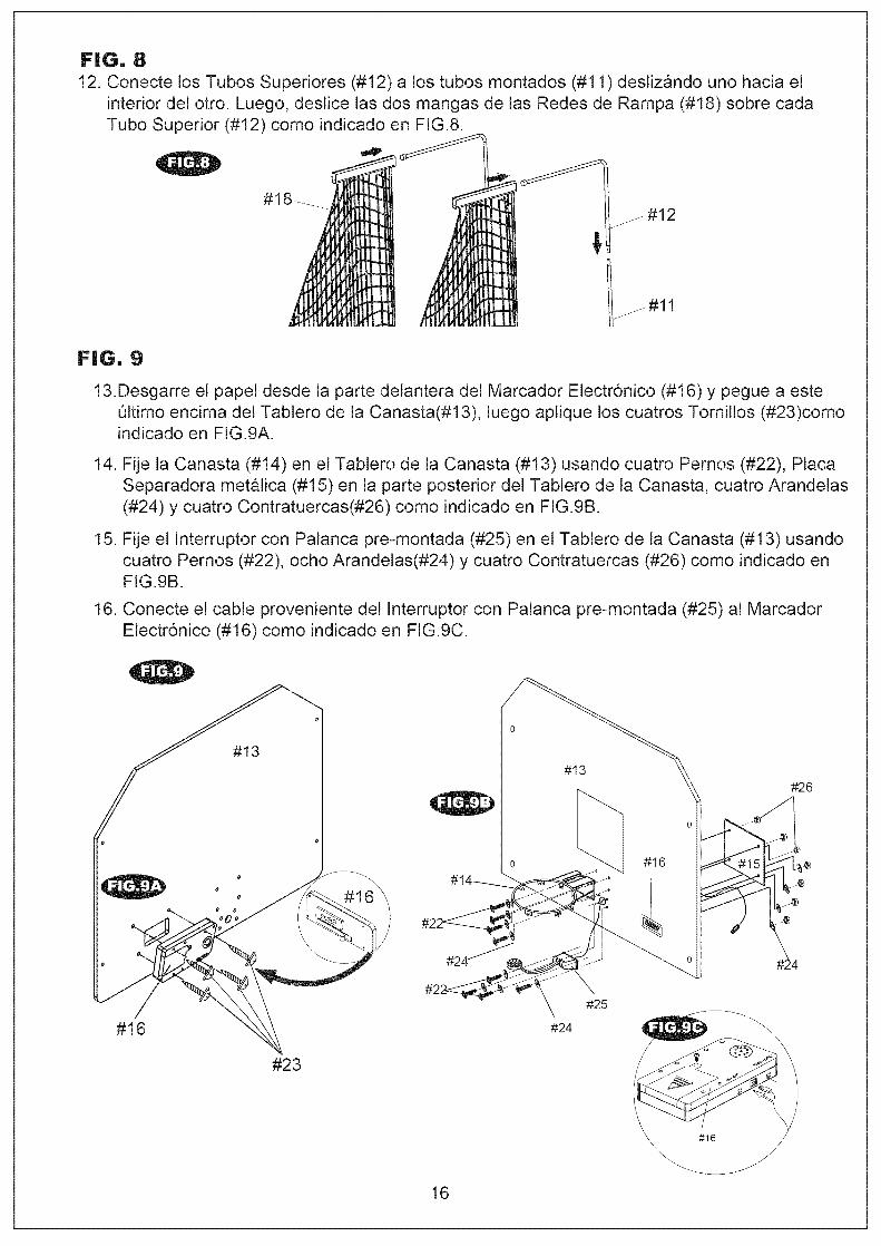
FiG. 812. Conecte los Tubos Superiores (#12) a los tubos montados (#11) desliz_ndo uno hacia el
interior del otro. Luego, deslice las dos mangas de las Redes de Rampa (#18) sobre cada
Tubo Superior (#12) como indicado en FIG.&
FiG. 9
13.Desgarre el papet desde la parte detantera del Marcador Electr6nico (#16) y pegue a esteOltimo encima del Tablero de la Canasta(#13), luego aplique los cuatros Tornillos (#23)comoindicado en FIG.9A.
14. Fije la Canasta (#14) en el Tablero de la Canasta (#13) usando cuatro Pernos (#22), PlacaSeparadora metalica (#!5) en la parte posterior del Tablero de la Canasta, cuatro Arandelas
(#24) y cuatro Contratuercas(#26) como indicado en FIG.9B.
15. Fije e! Interruptor con Palanca pre-montada (#25) en et Tablero de la Canasta (#13) usandocuatro Pernos (#22), ocho Arandelas(#24) y cuatro Contratuercas (#26) como indicado enFIG.9B.
16. Conecte el cable proveniente del Interruptor con Palanca pre-montada (#25) al MarcadorElectr6nico (#16) como indicado en FIG.9C.
#16
#13
o
o
o
#23
0
0 #16
#24
#25
0
#26
A_
\#24
16
#16
\

FiG. I 0
17. Deslice el Tubo de Soporte (#2) atraves de la manga adelante de la Red de Rampa (#18)usando un Perno (#21), una Arandela(#24) y una Contratuerca (#26) por cada lado comoindicado en FIG.10A.
18. Fije el Tablero de Canasta montado (#13) a! tubo superior montado usando cuatro Pernos
(#20), ocho Arandelas (#24) y cuatro Contratuercas (#26) como indicado en FIG. 10B.
#13
#24
#20
#2
#1
17

FiG. 11
19. Para facilitar su almacenamiento, este juego de baloncesto puede ser plegado f&cilmenteen forma vertical como indicado en FIG.11
20. Pliegue la parte final de la devoluci6n de pelota hacia el tablero de la Canasta e inserte laClavija de BIoqueo (#19) en la abertura como indicado en FIG.11.
*En Modo de juego use la clavija para fijar la rampa.
*En modo de almacenamiento use la clavija para
fijar la rampa en posici6n plegable.
1. Desatornille el perno usando un destornillador y abra la caja de la bateria.Inserte 4 pilas AA (que no va incluido) en orden de la poladdad como se
muestra en la tapa interior. Luego, t&pelo usando un destornillador. Prendala carga usando el interruptor de prender/apagar (on/off). (Si el juego nosera usado por un per6do prolongado, le recomendamos quitar las baterias).
2. PRENDER/APAGAR (ON/OFF) Sonido- cuando estas en un juego, use el \\ "O,/OFF"interruptor para PRENDER (ON) y APAGAR (OFF) el sonido.
3. Cuando el juego est& en Modo de Dormir, si un baloncesto ha marcado et puntaje, se vuelve aljuego y el marcador de puntos iniciara ua cuenta regresiva de 5 segundos.
4. Despues de finalizar el juego, Apague el marcador de puntos usando el interruptor de PRENDER
/APAGAR (ON/OFF). Nota: el marcador de puntos se apagara despues de 5 minutos al no serusado, sin embargo, le recomendamos apagar el interruptor PRENDER/APAGAR (ON/OFF) en
APAGAR (OFF) cuando el juego no seria continuado por un peri6do prolongado.
Estedispositivo cumple con las reglas del apartado 15 de la FCC.EIfuncionamiento est& sujeto a las siguientes condiciones:
(1) Estedispositivo no puede causar interferencias da_inas, y(2) Estedispositivo debe aceptar cualquier interferencia recibida,incluyendo interferenciasque puedan causar un funcionamiento nodeseado.
18


