Institutionalizing Modular Adaptable Ship...
18
Paper No. SNAME-047-2012 Doerry 1 Institutionalizing Modular Adaptable Ship Technologies N. H. Doerry (M) The U.S. Navy is tasked within a constrained budget with fulfilling its missions in an environment of evolving threats and a corresponding rapidly evolving mission system technology base. Modular Adaptable Ship (MAS) technologies enable the affordable transformation of a ship over its service life to maintain military relevance. The views expressed in this paper are those of the author and do not reflect the official policy or position of the Department of the Navy, the Department of Defense, or the U.S. Government. KEY WORDS: U.S. Navy; design (vessels); economics (design); modernization; systems engineering; warship INTRODUCTION The future is uncertain. The U.S. Navy is tasked with fulfilling its missions in an environment of evolving threats and a corresponding rapidly evolving mission system technology base. Affordability of our fleet is also of paramount concern. An alternative to the traditional approach of optimizing a point ship design to meet a specific set of fixed requirements is needed to maintain a sufficiently sized and relevant naval fleet that can be built and supported within the available budget. Historically, naval ship designs have included robustness features in the form of multi-mission capabilities and service life allowances to enable a limited capability to adapt to changing requirements over their service life. For most classes of ships, these robustness features have been adequate as indicated by these ships reaching or exceeding their design service life. Surface combatants on the other hand, have on average not been able to retain sufficient military relevance and on average have been decommissioned well before the end of their design service life. (Koenig 2009) Modular Adaptable Ship (MAS) technologies offer an opportunity for a ship to affordably transform its mission systems over its service life to maintain military relevance. These benefit has long been recognized and detailed by Jolliff (1974), Simmons (1975), Drewry (1975), Abbott (1977) and Broome (1982). In the 1970's and 1980's, MAS technologies were part of the SEAMOD and SSES Variable Payload Ship (VPS) concepts. Simmons for example states that as of the mid 1970’s: SEAMOD, then, can be summarized as the use of a variety of modular programs that serve the same general purpose: to uncouple the development of the payload from the development of the platform. This uncoupling yields two major benefits, and these are surrounded by a number of satellite benefits. The major benefits are: 1) By designing the combatant subsystems (payload) in parallel with the platform, rather than in series with it, a new ship can put to sea with a payload that is five to seven years newer than would be the case under current design procedures. 2) By permitting the relatively rapid changeout of equipment and integration of new items into a new weapon (or any other) system, it is possible to modernize ships without the time and money penalty currently incurred. While many MAS technologies have been available for many years, and in many cases been installed onboard ships in an ad hoc manner, a design methodology does not currently exist to establish a sound technical basis for determining how much of what type of modularity to install on a ship. Typically, these features are incorporated in a ship design by direction, because leadership recognizes the value of the modularity even though current cost and performance models often show an acquisition cost penalty is incurred to meet a specific set of requirements as compared to an optimized point design. Furthermore, although many promising technologies have been produced from the Science and Technology community, they have not been adequately developed for use in production across ship classes, nor has the organizational infrastructure been developed to support the technologies. These technologies have not been "institutionalized." This paper reviews the current status of a number of MAS technologies to include modular hull ships, mission bays, container stacks, weapon modules, aperture stations, off-board vehicles, Electronic Modular Enclosures (EME), and Flexible Infrastructure. These technologies are evaluated against criteria for their readiness for integration into a ship design. Additionally, this paper will describe and evaluate the current states of processes needed to successfully integrate MAS technologies on a ship. These processes include: cost estimation; valuing modularity and flexibility; acquisition, maintenance and modernization strategies; and optimizing ship configuration. The paper will introduce the possible use of Real Option Theory as part of the solution for measuring value. Additionally, alternate future methods will be explored to bound the range of required ship capabilities. These concepts will be united through an analogy to a classic feedback control system. Specific recommendations will be provided for future work. Modularity and flexibility is also incorporated within the boundaries of individual Hull, Mechanical, and Electrical (HM&E) systems and Mission Systems. Indeed, Naval Open Architecture does precisely this for Combat Systems.
-
Upload
nguyencong -
Category
Documents
-
view
218 -
download
2
Transcript of Institutionalizing Modular Adaptable Ship...

Paper No. SNAME-047-2012 Doerry 1
Institutionalizing Modular Adaptable Ship Technologies
N. H. Doerry (M)
The U.S. Navy is tasked within a constrained budget with fulfilling its missions in an environment of evolving threats
and a corresponding rapidly evolving mission system technology base. Modular Adaptable Ship (MAS)
technologies enable the affordable transformation of a ship over its service life to maintain military relevance.
The views expressed in this paper are those of the author and do not reflect the official policy or position of the
Department of the Navy, the Department of Defense, or the U.S. Government.
KEY WORDS: U.S. Navy; design (vessels); economics
(design); modernization; systems engineering; warship
INTRODUCTION
The future is uncertain. The U.S. Navy is tasked with fulfilling
its missions in an environment of evolving threats and a
corresponding rapidly evolving mission system technology base.
Affordability of our fleet is also of paramount concern. An
alternative to the traditional approach of optimizing a point ship
design to meet a specific set of fixed requirements is needed to
maintain a sufficiently sized and relevant naval fleet that can be
built and supported within the available budget. Historically,
naval ship designs have included robustness features in the form
of multi-mission capabilities and service life allowances to
enable a limited capability to adapt to changing requirements
over their service life. For most classes of ships, these
robustness features have been adequate as indicated by these
ships reaching or exceeding their design service life. Surface
combatants on the other hand, have on average not been able to
retain sufficient military relevance and on average have been
decommissioned well before the end of their design service life.
(Koenig 2009)
Modular Adaptable Ship (MAS) technologies offer an
opportunity for a ship to affordably transform its mission
systems over its service life to maintain military relevance.
These benefit has long been recognized and detailed by Jolliff
(1974), Simmons (1975), Drewry (1975), Abbott (1977) and
Broome (1982). In the 1970's and 1980's, MAS technologies
were part of the SEAMOD and SSES Variable Payload Ship
(VPS) concepts. Simmons for example states that as of the mid
1970’s:
SEAMOD, then, can be summarized as the use of a
variety of modular programs that serve the same
general purpose: to uncouple the development of the
payload from the development of the platform. This
uncoupling yields two major benefits, and these are
surrounded by a number of satellite benefits. The
major benefits are:
1) By designing the combatant subsystems (payload)
in parallel with the platform, rather than in series with
it, a new ship can put to sea with a payload that is five
to seven years newer than would be the case under
current design procedures.
2) By permitting the relatively rapid changeout of
equipment and integration of new items into a new
weapon (or any other) system, it is possible to
modernize ships without the time and money penalty
currently incurred.
While many MAS technologies have been available for many
years, and in many cases been installed onboard ships in an ad
hoc manner, a design methodology does not currently exist to
establish a sound technical basis for determining how much of
what type of modularity to install on a ship. Typically, these
features are incorporated in a ship design by direction, because
leadership recognizes the value of the modularity even though
current cost and performance models often show an acquisition
cost penalty is incurred to meet a specific set of requirements as
compared to an optimized point design.
Furthermore, although many promising technologies have been
produced from the Science and Technology community, they
have not been adequately developed for use in production across
ship classes, nor has the organizational infrastructure been
developed to support the technologies. These technologies have
not been "institutionalized."
This paper reviews the current status of a number of MAS
technologies to include modular hull ships, mission bays,
container stacks, weapon modules, aperture stations, off-board
vehicles, Electronic Modular Enclosures (EME), and Flexible
Infrastructure. These technologies are evaluated against criteria
for their readiness for integration into a ship design.
Additionally, this paper will describe and evaluate the current
states of processes needed to successfully integrate MAS
technologies on a ship. These processes include: cost
estimation; valuing modularity and flexibility; acquisition,
maintenance and modernization strategies; and optimizing ship
configuration. The paper will introduce the possible use of Real
Option Theory as part of the solution for measuring value.
Additionally, alternate future methods will be explored to bound
the range of required ship capabilities. These concepts will be
united through an analogy to a classic feedback control system.
Specific recommendations will be provided for future work.
Modularity and flexibility is also incorporated within the
boundaries of individual Hull, Mechanical, and Electrical
(HM&E) systems and Mission Systems. Indeed, Naval Open
Architecture does precisely this for Combat Systems.

Paper No. SNAME-047-2012 Doerry 2
Furthermore, the Vertical Launching System (VLS) is an
outstanding example of a system that enables upgrading of
munitions without costly changes to launcher systems. While
these applications of modularity are important, this paper will
not focus on them. This paper will instead focus on integration
across systems.
DESIGN STRATEGIES FOR UNCERTAINTY
As shown in Figure 1, if the requirements for a ship or system
are fixed, then it is appropriate to have a ship design that too is
fixed. The appropriate design approach would be to use
optimization methods to develop the best design to meet the
fixed set of requirements. In fact many of the Navy's
auxiliaries, such as oilers, have requirements that generally are
unchanged over their service life. In the commercial marine
sector, many ship types such as cruise ships, ferries, tankers, and
ore carriers fall into this category. Because the requirements are
fixed, little incentive exists to provide flexibility in their design.
If a ship's requirements are expected to change significantly
over its service life, two design strategies have applicability.
Robust Design strives to incorporate into the initial design the
capability to satisfactorily meet the evolving ships requirements,
even though they are not fully known at the time of design. The
goal is not to optimize the design for a specific set of
requirements, but instead to achieve sufficiently acceptable
performance over a broad range of possible sets of
requirements.
Modular Adaptable Design on the other hand, presumes that the
set of requirements possible but unknown at the time of design
for a ship is so great that a ship designed using robust design
methods alone would be prohibitively expensive. Instead the
ship is designed to incorporate options such that investments
and decisions as to the ship's capability in the future is deferred
to the future. These options are expressed in terms of modules
and design adaptability. Modular Adaptable Design therefore
incorporates features for morphing a ship's capabilities over
time to match the evolving requirements. A successful
implementation of Modular Adaptable Design requires not only
the flexibility within the ship, but also the ability to monitor the
changing requirements over the ship's service life, and having
the modernization processes to translate those changing
requirements into evolutionary changes to the ship. (Abbott
2003)
Requirements
Fixed
Requirements
Changing
Design
Fixed
Design
Flexible
Robust Design(service life allowance
Build in capability to meet
threat over service life)
Optimized
Point Design(many commercial ships
& Navy Auxiliaries)
Modular
Adaptable(Mission Modules
Flexible Infrastructure etc.
Morph ship to match threat
Over service life)
(Little Incentive)
Figure 1: Design Strategies
Historically, naval warships have been designed primarily to a
fixed set of requirements. The goal of design has been to
minimize the cost, either acquisition or total ownership, while
meeting the specified requirements. The inclusion of service
life allowances for distributed systems, weight and stability has
been the predominate accommodation for future growth. The
value of the service life allowance used in a particular design
was typically based on design criteria and design practices based
on historical growth. Of particular note, area and volume have
not often included service life allowances (Designs do
incorporate a 10% accommodation margin and a number of
ships deliver with unassigned space). Prior to recent topside
designs with reduced radar signatures, extra area and volume
could always be added later in a ship design by incorporating an
additional deck house to the superstructure. (Gale 1975) The
weight and KG service life allowance provided the means for
adding the additional deckhouse.
In examining Figure 1, it is clear that the historic practice is a
combination of the top two quadrants characteristic of a fixed
design: Optimized point design and robust design. For surface
combatants, the historic evidence since World War II has shown
that this design strategy has not proven successful on average to
ensure our surface combatants achieve their design service life.
One study calculated the average actual service for cruisers to
be 26.3 years and destroyers to be 25.4 years. These average
actual service lives are well short of the design service lives of
30 to 35 years. (Koenig 2009)
A different design strategy is needed to ensure surface
combatants remain militarily relevant over their design service
life and not decommissioned early. Figure 1 suggests that in an
era of changing requirements, a design strategy based on a
combination of robust design and modular adaptable design
would result in ships more likely to remain militarily relevant
over their design service life.
Modular adaptable design is not a euphemism for a modular
single mission ship such as the Littoral Combat Ship (LCS).
LCS is one example of an application of modular adaptable
design. Multi-mission ships, such as cruisers and destroyers can
(and do) incorporate modular adaptable design. The key to
modular adaptable design is incorporating options in the design
to be able to defer the exact configuration of the ship to that
point in time when the requirements are known, and to have the
capability to affordably modify the ship's configuration to meet
the requirements when they become known.
The point in time when the options can be exercised are often a
function of the modular adaptable technologies. Examples
include:
- At the time of a specific mission, such as the
weapons load-out of an aircraft.
- Prior to a ship's deployment, such as the weapons
load-out of a VLS, the composition of an aircraft
carrier’s air wing, the installation of a specific
mission module on an LCS, or Alteration Installation
Team (AIT) installation of new capabilities.
Paper No. SNAME-047-2012 Doerry 3
- During a major modernization.
- After start of construction, but before ship delivery or
completion of Post-Shakedown Availability (PSA).
- Between different ship acquisitions, such as flight
upgrades.
MAS technologies provide options "in" the design. These
options "in" the design are contrasted from options "on" the
design that exist, but have not been an explicit design feature.
Options "on" the design reflect the reality that one can always
modify a ship to meet new requirements if one is willing to
expend the time and resources to do so.
INSTITUTIONALIZING TECHNOLOGY
To date MAS technology has been incorporated into ship
designs in an unstructured manner. In some cases, the MAS
technology has been specified as a requirement by the customer,
rather than a solution to addressing uncertain requirements. In
other cases program managers have incorporated modular
adaptable technologies because they intuitively know the value,
even when cost and net present value methods based on fixed
requirements indicate a more optimized solution would rank
higher. Program managers have also incorporated these
technologies when the inherent commonality of components
enables cost sharing among multiple programs or if the need for
a specific future upgrade is clearly known and defendable. The
incorporation of Flexible Infrastructure on a number of ship
classes is a good example of the latter case.
In general, MAS technologies and associated flexible design
methods are not currently institutionalized within the U.S. Navy.
As described by Doerry (2006), a technology is institutionalized
when:
- An engineer has sufficient knowledge of the
technology to predict its performance and impact on
the product design at all stages of design.
- An engineer has sufficient knowledge of the
technology to predict the engineering effort required
to integrate the technology into the product design in
all stages of design
- An engineer has sufficient knowledge of the
technology to predict the cost impact of the
technology on the production cost of the end product.
- An engineer is able to adequately specify the
technology in a product specification to enable the
producer to adequately bid a price and produce an
acceptable product.
- A customer is satisfied with the performance of the
end product, having only characterized the
performance requirements with relatively few
parameters. In other words, customer expectations
are met for product performance in areas that have
not been explicitly specified.
For the ship acquisition program manager, institutionalizing a
technology reduces the cost, schedule, and performance risk
associated with integrating the technology into a ship design.
Technology decisions are typically made during the first year
following the analysis of alternatives through a series of trade
studies that comprise pre-preliminary and early preliminary
design. Mature technologies with an acceptable risk best
meeting product requirements (including affordability) are
generally preferred.
Likewise, new processes are generally not accepted into the ship
design process unless deemed mature by the ship design
manager and program manager.
Technical Maturity
The following criteria are proposed to evaluate technologies for
their maturity and readiness for integration into a ship:
- Technology Readiness Level 7 achieved (TRL 7)
- Industrial base ready to produce the product
(Industry)
- Approved specification and/or standard drawings
exist (Specifications)
- Approved design guidance and/or handbooks exist
(Handbook)
- Government and industry are able to accurately and
promptly predict work and costs (Cost)
- Government is able to accurately and promptly
evaluate value and cost benefit over the life of the
ship including an understanding of the impact of
changing requirements (Value)
The Department of Defense defines TRL 7 as:
"System prototype demonstration in an operational environment
Prototype near, or at, planned operational system: Represents a
major step up from TRL 6, requiring demonstration of an actual
system prototype in an operational environment (e.g., in an air-
craft, in a vehicle, or in space)" (DOD 2011)
While achieving these criteria by early Preliminary Design is
not strictly required, any shortcoming is a program risk that
must be weighed against the potential benefit. Established
technologies will have achieved these criteria and thus have an
incumbent’s advantage over a new technology. Designers and
program managers generally incorporate incumbent
technologies into a baseline design without significant analysis,
unless a different technology can prove it is better. A new
technology must achieve the criteria listed above to become the
incumbent technology.
Process Maturity
The previous section discussed measuring the maturity of
technologies associated with equipment and systems installed on
a ship. Institutionalizing the processes associated with
designing, maintaining, and modernizing ships’ MAS
technologies is also critical. The following criteria are proposed
Paper No. SNAME-047-2012 Doerry 4
to evaluate processes for their maturity and readiness for
integration into a ship acquisition program:
- Process defined in a handbook or guide (Handbook)
- Workforce trained and ready to implement the
process (Training)
- Process tools exist, are ready, and available to the
workforce (Tools)
- Valid data required by the process is available to the
workforce (Data)
MODULAR ADAPTABLE SHIP TECHNOLOGIES
The following sections present eight modular adaptable
technologies and evaluate them for technical maturity. The
evaluation will simply assign one of the following to describe
the work needed to achieve the criteria:
- Done: The criteria has been met
- Working: Ongoing efforts are working to meet the
criteria, or the criteria has been partially fulfilled
- Not Started: No efforts are currently underway to
meet the criteria.
The eight technologies described here are not exhaustive, but
are representative of the many MAS technologies that have been
explored and in some cases implemented. For more
technologies, see Abbott (2006), Bertram (2005) and Jolliff
(1974).
Modular Hull Ships
Modular hull ship technology provides in the ship design
options for inserting different parallel midbodies. These options
can be designed to be exercised only in new construction, or
could additionally be designed to be exploited during a major
modernization.
Modular Hull Ship technology facilitates several different
acquisition strategies including"
- Using a common bow and stern for several classes of
ships. An example could be common bows and
sterns for a hospital ship, a tender, and a command
ship. The application specific systems and spaces
would be in the parallel midbody. By using the
common bow and stern, design and production
efficiencies can be realized by effectively procuring a
larger class size.
- Using a common bow and stern for different flights
of one type of a ship. Concentrate mission systems
and other systems that are expected to experience the
maximum change over the design life of the class of
ships into the parallel midbody. This way the non-
recurring cost of keeping the ships relevant is
minimized while keeping the learning curve benefits
in preserving the same bow and stern.
- Constructing and testing a new parallel midbody for
an in-service ship prior to a major modernization
availability. Minimize the amount of time the ship is
in the shipyard and not available for operational
tasking.
While the U.S. Navy has inserted parallel midbodies into ships
in all stages of design, construction, and operation, this practice
was not usually considered in the initial design of the ship.
Examples include the conversion of Skipjack (SSN 585) class
attack submarines into the George Washington (SSBN 598)
class of ballistic missile submarines, the modification of the
Jimmy Carter (SSN 23), and the "Jumboized" Cimarron
(AO177) class of fleet oilers. In these cases the option to insert
the parallel midbody was an option exercised "on" these ships
rather than an option that was designed "in" at the time the ship
was conceived. Unfortunately, we do not know if any time or
resources could have been saved had the option to insert parallel
midbody been designed "in" during the initial ship design.
The technology or "knowledge" needed to design a modular hull
ship is well understood and well within the capability of
industry to execute. As an extension to the Modular Hull Ship
concept, the Dutch Schelde shipyard has developed the Ship
Integrated Geometrical Modularity Approach (SIGMA) concept
based on standard hull sections. SIGMA allows Schelde to
rapidly develop a low risk detail design for a wide range of
foreign military sales customers. Ships of three different
lengths (91, 98, and 105 meters) with the same beam (13
meters) have been delivered to two customers.
Within the U.S. Navy however, no work has been conducted to
develop specifications or handbooks to implement a modular
hull ship as part of an initial ship design. Furthermore methods
to determine the value and potential cost benefit of modular hull
ships have not been formalized. The maturity of Modular Hull
Ship technology in the United States is evaluated as:
TRL 7 DONE
Industry DONE
Specification NOT STARTED
Handbook NOT STARTED
Cost NOT STARTED
Value NOT STARTED
Mission Bays
Each of the two LCS variants includes a mission bay to house
elements of mission packages. For LCS, mission packages are
composed of mission modules, aircraft, and crew detachments
to support the mission modules and aircraft. Mission modules
in turn are compose of mission systems and support equipment.
The mission systems are weapons, sensors, and vehicles. The
support equipment consists of support containers,
communications systems, and computing environment. The
support containers house much of the mission module
equipment and are based on standard ISO containers (Figure 2).
These ISO containers are secured to the deck of the mission bay
and are not intended to be used operationally in a container
stack (They may be transported by container ship). Interface

Paper No. SNAME-047-2012 Doerry 5
standards have been developed to provide distributed system
support to these containers. The technology for a mission bay is
well established (Figure 3) and the specifications are captured in
the LCS ship specifications as well as the previous X-craft
specification (FSF-1 Sea Fighter). The remaining issues deal
with generalizing the concept in design guidance. Issues such as
the following should be addressed:
- How large should the Mission Bay be?
- What is the relative value of different size Mission
Bays?
- What type of distributed services should be made
available to mission modules?
- How should the ship's distributed systems be sized to
account for the mission modules?
- The interfaces between the mission module
containers and the ship should be defined as a
generalized interface that is not unique to a given
ship class. The interfaces developed for LCS are a
good starting point.
Figure 2: LCS Outfitted Container for Mission Bay
Figure 3 Mission Bay on FSF-1 Sea Fighter
The NATO Study Group SG-150 recently completed a report
(NATO 2011) that advocated the development of NATO
standards for various mission module containers to support
Humanitarian Assistance/Disaster Relief (HA/DR), counter-
piracy, and harbor protection. Follow on work to implement the
report's recommendations has been proposed.
Based on the work accomplished to date, the maturity of
integrating Mission Bays into U.S. warships is evaluated as:
TRL 7 DONE
Industry DONE
Specification WORKING
Handbook NOT STARTED
Cost DONE
Value NOT STARTED
Container Stacks
ISO containers are used throughout the world for intermodal
transport of freight. Containerships have specialized systems to
securely connect containers to each other and the ship. Below
the weather deck, container guides are typically used to position
and secure the containers (Figure 4). Above deck, lashing
systems, locking systems, or buttress systems are used. (Figure
5 and Figure 6)
Using ISO containers for military purposes other than freight
has proven attractive and viable. The LCS for example,
extensively uses ISO compliant containers for its mission
systems to simplify "shipping, storage, availability of correct
handling equipment, and container movement from shore to ship
and ship to shore." (PEO LCS 2011). In LCS and many of the
other military applications to date, the containers have been
secured to a deck and typically do not include the stacking of
containers. Access to the interior of the container is via a door
at one end of the container. These applications of containers
apply to Mission Bays.
If instead, containers are used as part of container stacks on
existing container ships, or if container stacks become part of
the design of a future combatant, then provisions must be made
for personnel access and distributed system routing. Note that
container lashing systems such as those shown in Figure 5 can
interfere with container access.
This concept is not new. In the 1970’s and 1980’s the United
States developed the ARAPAHO system to provide ASW
helicopter capability to container ships within a convoy using a
series of modular ISO containers. In 1983 the Royal Navy
leased the ARAPAHO system and installed it on a containership
which was subsequently commissioned as the Royal Fleet
Auxiliary (RFA) Reliant. (Rodrick 1988) FLIGHT
International (1984), reported that although the Royal Navy was
able to successfully operate helicopters using ARAPAHO on
RFA Reliant, several design issues emerged. These issues
included:
- The hangar spanned multiple containers and the
joints between containers were not watertight.
- ISO containers were not always the optimal shape or
size for workshops

Paper No. SNAME-047-2012 Doerry 6
- The steel mesh flight deck surface caused accelerated
wear of vehicle tires.
- The containership hull form rolls significantly in
heavy weather
RFA Reliant was subsequently decommissioned in 1986.
Detail engineering drawings or specifications for the
ARAPAHO modules have not been preserved within the U.S.
Navy.
As described by Littlefield (2012), the Defense Advanced
Research Project Agency (DARPA) Tactical Expandable
Maritime Platform (TEMP) program is developing similar
technology to perform the Humanitarian Assistance / Disaster
Relief (HA/DR) mission and potentially other combatant
missions from containership vessels of opportunity. TEMP is
developing specifications for core and mission modules. The
list of core modules that implement basic infrastructure
functions is shown in Figure 8. TEMP has also documented
approaches for interconnecting the containers with distributed
systems as shown in Figure 9.
Figure 4: Cell Guides in a Container Ship (http://en.wikipedia.org/wiki/File:Containerlader%C3%A4ume_Schiff_retouched.jpg)
Figure 5: Container Lashing Systems (UK P&I Club 2004)
Figure 6: Twist Lock and Lashing Rods (Picture by Hervé Cozanet from the marine-marchande.net)
Figure 7: RFA Reliant with ARAPAHO (RFA Nostalgia)

Paper No. SNAME-047-2012 Doerry 7
Figure 8: TEMP Core Modules
Figure 9: TEMP Distributed Systems Concepts
The Military Sealift Command (MSC) operates two Aviation
Logistics Support ships: SS Wright (T-AVB 3) and SS Curtiss
(T-AVB 4) (Figure 10). These ships provide intermediate
maintenance facilities for the Marine Corps packaged in
containers. While these facilities are primarily designed to
operate ashore, these ships are configured to allow maintenance
operations to be conducted onboard ship.
Figure 10: SS Curtiss (T-AVB 4)
The existing ISO standards for the containers and tie down
system are mature for transporting containers onboard a ship.
Based on the past success with ARAPAHO and the Aviation
Logistics Support ships, the basic technology associated with
implementing mission and support services within ISO
containers in container stacks is well known. The ongoing work
with DARPA’s TEMP program is establishing the industry base,
specifications, and handbooks for employing containers that are
designed to be operational while onboard ship. Little work has
been done to date to enable the Government or shipbuilders to
properly cost ships or establish good value metrics for
incorporating this technology. The maturity of Container Stack
technology in the United States is evaluated as:
TRL 7 DONE
Industry WORKING
Specification WORKING
Handbook WORKING
Cost NOT STARTED
Value NOT STARTED
Weapon Modules
Weapons modules were initially developed under the SEAMOD
program in the early 1970’s and were further matured during the
Ship Systems Engineering Standards (SSES) program in the
1980’s. Within the U.S. Navy, the 32 cell (“A” Module) and 64
cell (“B” Module) VLS installed on the DDG 51 class are the
best known examples of weapon modules (Figure 11). SSES
created standards for a family of four weapons modules as
shown in Figure 12. While VLS is the only U.S. application of
the SSES module definitions, Blohm + Voss of Germany
incorporated the SSES standards for weapons modules into their
MEKO small warship product lines. The use of weapons
modules enabled Blohm + Voss to rapidly and affordably create
customized warship designs for domestic and foreign military
sales using standard components. Blohm + Voss sold over sixty
MEKO vessels in over 15 configurations.
While generalized interface drawings and standards do not exist
for the SSES modules, considerable detail is provided by
NAVSEA (1985). The following DDG 51 Contract Drawings
and Contract Guidance Drawings could form the basis of
generalized interface drawings.

Paper No. SNAME-047-2012 Doerry 8
Contract Drawings 5774129 Forward A-Size Weapon Zone 5774130 Aft B-Size Weapon Zone
Contract Guidance Drawings 802-5959340 A-Size Structural Guidance Drawing 802-5959341 A-Size SIR Support Systems Composite Guidance Drawing
802-5959342 A-Size Fluid Systems Guidance Drawing
802-5959343 A-Size Fan Room and Ducting Guidance Drawing 802-5959344 B-Size Structural Guidance Drawing
802-5959345 B-Size SIR Support Systems Composite Guidance Drawing
802-5959346 B-Size Fluid Systems Guidance Drawing 802-5959347 B-Size Fan Room and Ducting Guidance Drawing
Figure 11: Standard Missile Three (SM-3) emerging from a
vertical launching system (VLS)
Figure 12: SSES Weapons Modules (Abbott 1994)
Within the U.S. Navy, there has not been a strong demand for
weapon modules. VLS and 5 inch guns have provided
flexibility and adaptability through their munitions. Except for
“repair by replacement” concepts, complete replacement of the
VLS or gun has not been necessary. Gun technology in
particular has not radically changed over the past twenty years.
In fact the SSES standards for weapon modules have not been
applied to guns within the U.S. Navy. The LCS provides a gun module that is interchangeable with a missile launcher module.
Although these modules use interfaces that are similar to the
SSES “AA” weapons module standards, they are unique to the
LCS (Figure 13.)
With the ongoing development of railguns and directed energy
weapons, it may be desirable now to employ weapon modules
for gun systems. These weapons modules could decouple ship
development timelines from the advanced weapon system
developments. Once an advanced weapon is ready for fleet
introduction, it could then be more easily backfit into the in-
service ships.
Figure 13: Littoral Combat Ship (LCS) Weapon Station
Module
The technology for implementing weapon station modules is
well understood and within the capability of industry. Ship
specific interface specifications exist, and could be adapted into
general purpose interface standards.
The general process for incorporating weapon modules are
described in two guides from NAVSEA 05T: "A Guide for the
Design of Modular Zones on U.S. Navy Surface Combatants"
by Vasilakos et al. (2011) and "Modular Adaptable Ship
(IMAS) Total Ship Design Guide for Surface Combatants" by
Garver et al. (2011). While these guides provide good
information, they should be formalized into a Design Data Sheet
or a formal NAVSEA technical document (such as a manual
associated with a NAVSEA instruction or a NAVSEA
Technical Manual) approved by the NAVSEA Standards
Improvement Board (SIB).
The ability to accurately predict the impact of weapon station
modules on acquisition or life cycle cost is extremely limited at
this time. Likewise, a standard method for evaluating the value
of weapon station modules as a function of time has not been
established. The maturity of Weapon Modules technology in
the United States is evaluated as:

Paper No. SNAME-047-2012 Doerry 9
TRL 7 DONE
Industry DONE
Specification WORKING
Handbook WORKING
Cost NOT STARTED
Value NOT STARTED
Aperture Stations
The topside arrangements of all the Radio Frequency (RF)
transmit and receive antennas is a challenging task. Ensuring
electromagnetic compatibility (EMC) while minimizing
electromagnetic interference (EMI) and antenna blockages is
difficult even with a fixed set of known RF equipment. Over
the service life of a ship however, these RF equipment may
require replacement or upgrading to remain interoperable with
the fleet and militarily relevant. Currently, replacement and
modification of RF equipment and their associated antennas are
not extensively considered or accounted for in shipboard topside
design. Upgrading arrays and antennas can be extremely
expensive. In particular, phased array radars have traditionally
been tightly integrated into the ship superstructure design.
When these radars become obsolete, the cost of modernization
may drive a decision to decommission the ship prior to its
design service life rather than invest in updating the radar.
Aperture stations apply modularity concepts to RF antennas and
their shipboard integration. The methods to implement aperture
stations are not fully developed or institutionalized. The
Advanced Enclosed Mast / Sensor (AEM/S) demonstrated on
U.S.S. Arthur W. Radford (DD 968) and incorporated into the
U.S.S. San Antonio (LPD 17) design uses a frequency selective
surface radome to reduce radar cross-section and help with
EMC and EMI. (Compneschi 2001) Although facilitating
upgrading and modernization of antennas was an objective of
AEM/S, this capability has not been demonstrated.
Specifications and handbooks for developing an AEM/S for a
new class of ships do not currently exist. Some AEM/S
technology did transition to the DDG 1000 program.
The ONR Integrated Topside (INTOP) Innovative Naval
Prototype (INP) program is approaching the problem by using
integrated, multifunction and multibeam arrays to fulfill
multiple functions that currently require dedicated antenna
systems. (Figure 14) By significantly reducing the number of
antennas, the EMI and EMC challenges are simplified.
As described by Tavik et al. (2010):
"The InTop program objectives include the following:
• Develop, integrate, and demonstrate new apertures
and subsystems that will support RF multifunctionality
and that are based on modular, scalable, open
architecture, in order to enable greater flexibility to
adapt platform capabilities to rapidly changing tactical
and strategic environments.
• Demonstrate the integration and coordinated control
of many critical shipboard RF functions implemented
across a multitude of systems and subsystems, via a
common resource allocation manager (RAM), in order
to optimize the use of available RF spectrum and
hardware.
• Develop, with the Naval Sea Systems Command
(NAVSEA), ship design initiatives to incorporate
InTop integrated communications/sensor systems to
optimize ship size and performance factors.
The goal of the InTop program is to evolve to an
integrated Navy capability 10 to 12 years in the future
that has the following characteristics:
• Modular, open RF architecture
• Software-defined functionality
• Synchronized RF functions for mission support and
EMI mitigation
• Reduced size, weight, and power requirements
relative to a federated topside
• Reduced cost (acquisition and total ownership)
relative to a federation of systems
• Scalability in order to derive systems of appropriate
capability to match each particular platform’s
requirements
• Reduced life-cycle costs
• More RF functions optimally sited topside
• Rapid adaptability to new threats/requirements
through software upgrades
• Integrated antenna/array topside designs that are
seamlessly compatible with the associated platform
architecture and design
Figure 14: Modular Mechanical Architecture concept for
INTOP antenna subsystem (Courtesy ONR)
Considerable work remains to institutionalize Aperture Station
technology. Although AEM/S technology is at sea today, it is
not clear if the technology has been captured in a manner that it
could be successfully employed at reasonable cost on a new ship
acquisition. The InTop technology has not yet achieved TRL 7,
Generalized specifications, standards, and design guidance do
not exist and the ability of the Navy to accurately predict cost or
benefit is lacking. The maturity of Aperture Station technology
in the United States is evaluated as:
Paper No. SNAME-047-2012 Doerry 10
TRL 7 WORKING
Industry WORKING
Specification NOT STARTED
Handbook NOT STARTED
Cost NOT STARTED
Value NOT STARTED
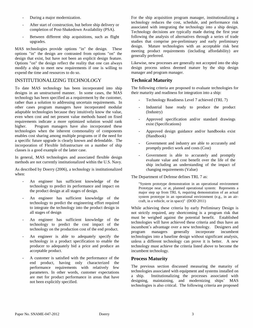
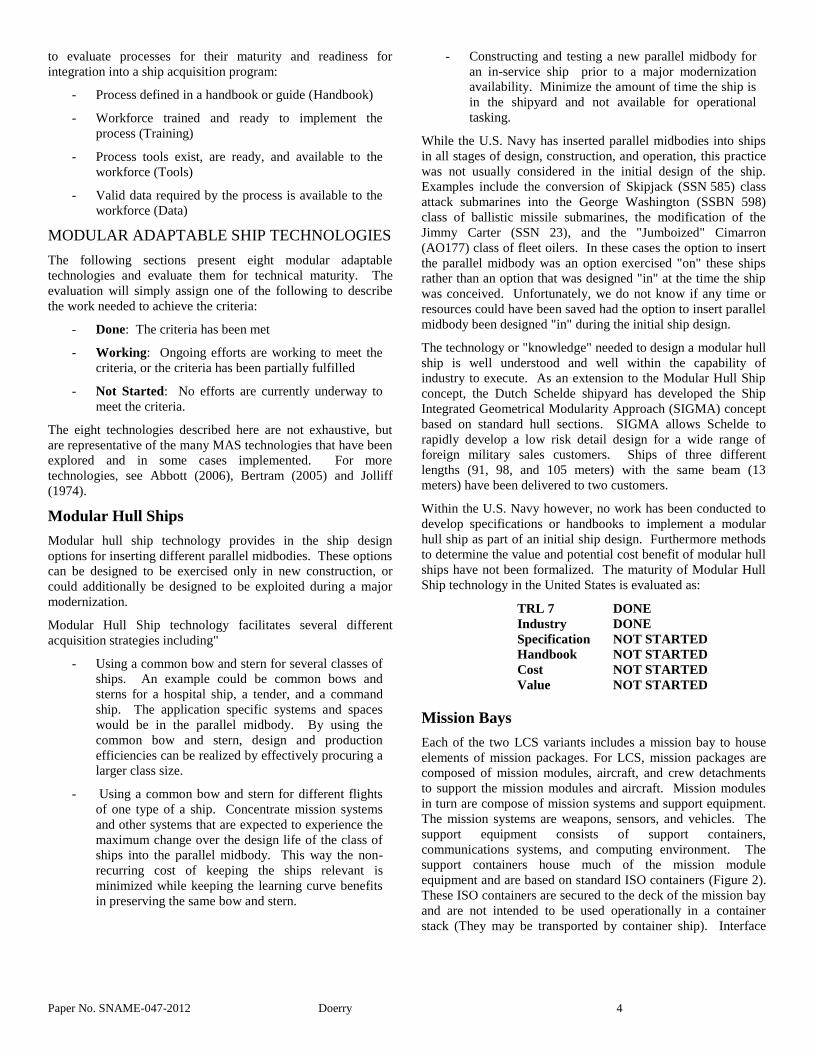
Off-Board Vehicles
Surface combatants have successfully integrated small boats and
helicopters for many years. Especially since helicopter decks
have been sized to support the H-60 family of airframes, it has
been relatively straightforward for surface combatants to host a
wide variety of rotary aircraft. Likewise, the Navy's transition
from motor whaleboats to Rigid-Hull Inflatable Boats (RHIB)
was not traumatic. More recently however, the U.S. Navy has
started to operate with unmanned vehicles as shown in Figure
15 and Figure 16. Standardized methods to launch and recover
these vehicles, replenish them, or control them have not been
established and will likely evolve in the coming years.
Figure 15: MQ-8B Fire Scout Unmanned Air Vehicle
Figure 16: Unmanned Influence Sweep System (UISS)
Based on the ongoing work to integrate unmanned vehicles
into LCS and other ships, this technology is evaluated as:
TRL 7 WORKING
Industry WORKING
Specification WORKING
Handbook WORKING
Cost WORKING
Value NOT STARTED
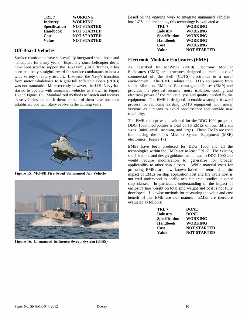
Electronic Modular Enclosures (EME)
As described by McWhite (2010) Electronic Modular
Enclosures (EME) are structures designed to enable use of
commercial off the shelf (COTS) electronics in a naval
environment. The EME isolates the COTS equipment from
shock, vibration, EMI and Electromagnetic Pulses (EMP) and
provides the physical security, noise isolation, cooling and
electrical power of the requisite type and quality needed by the
equipment. The EME is designed to enable a straight forward
process for replacing existing COTS equipment with newer
versions as a means to avoid obsolescence and provide new
capability.
The EME concept was developed for the DDG 1000 program.
DDG 1000 incorporates a total of 16 EMEs of four different
sizes (mini, small, medium, and large). These EMEs are used
for housing the ship's Mission System Equipment (MSE)
electronics. (Figure 17)
EMEs have been produced for DDG 1000 and all the
technologies within the EMEs are at least TRL 7. The existing
specifications and design guidance are unique to DDG 1000 and
would require modification to generalize for broader
applicability to other ship classes. While material costs for
procuring EMEs are now known based on return data, the
impact of EMEs on ship acquisition cost and life cycle cost is
not well understood to enable accurate trade studies in other
ship classes. In particular, understanding of the impact of
enclosure tare weight on total ship weight and cost is not fully
developed. Likewise methods for measuring the value and cost
benefit of the EME are not mature. EMEs are therefore
evaluated as follows:
TRL 7 DONE
Industry DONE
Specification WORKING
Handbook WORKING
Cost NOT STARTED
Value NOT STARTED
Paper No. SNAME-047-2012 Doerry 11
Figure 17: DDG 1000 Electronic Modular Enclosures
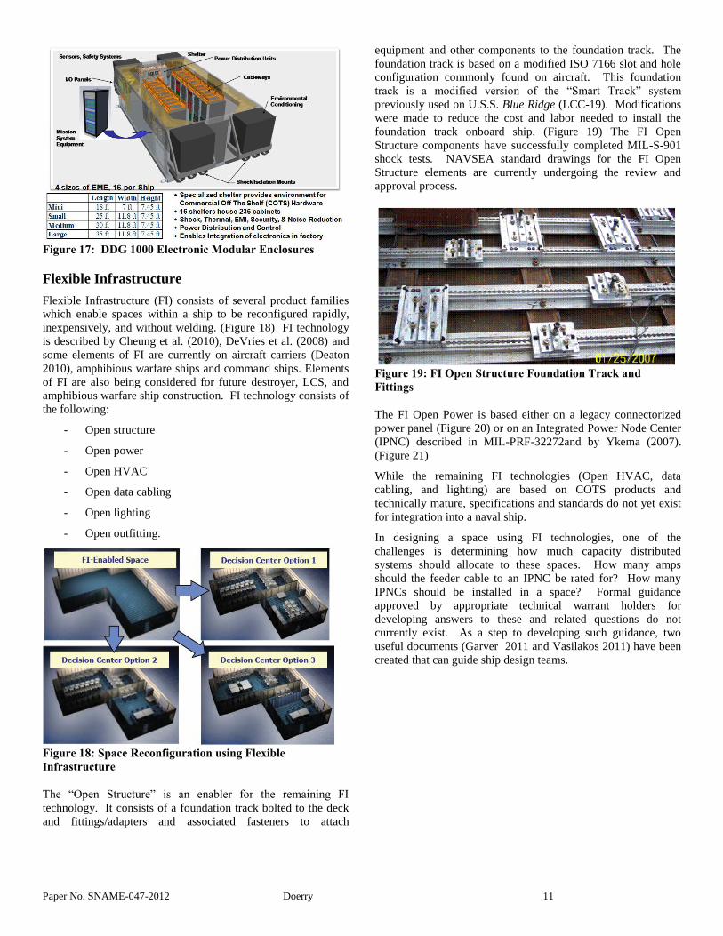
Flexible Infrastructure
Flexible Infrastructure (FI) consists of several product families
which enable spaces within a ship to be reconfigured rapidly,
inexpensively, and without welding. (Figure 18) FI technology
is described by Cheung et al. (2010), DeVries et al. (2008) and
some elements of FI are currently on aircraft carriers (Deaton
2010), amphibious warfare ships and command ships. Elements
of FI are also being considered for future destroyer, LCS, and
amphibious warfare ship construction. FI technology consists of
the following:
- Open structure
- Open power
- Open HVAC
- Open data cabling
- Open lighting
- Open outfitting.
Figure 18: Space Reconfiguration using Flexible
Infrastructure
The “Open Structure” is an enabler for the remaining FI
technology. It consists of a foundation track bolted to the deck
and fittings/adapters and associated fasteners to attach
equipment and other components to the foundation track. The
foundation track is based on a modified ISO 7166 slot and hole
configuration commonly found on aircraft. This foundation
track is a modified version of the “Smart Track” system
previously used on U.S.S. Blue Ridge (LCC-19). Modifications
were made to reduce the cost and labor needed to install the
foundation track onboard ship. (Figure 19) The FI Open
Structure components have successfully completed MIL-S-901
shock tests. NAVSEA standard drawings for the FI Open
Structure elements are currently undergoing the review and
approval process.
Figure 19: FI Open Structure Foundation Track and
Fittings
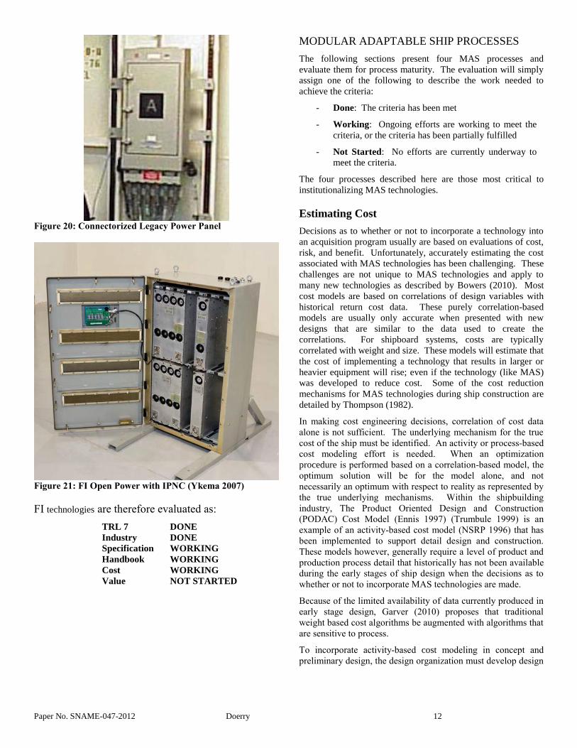
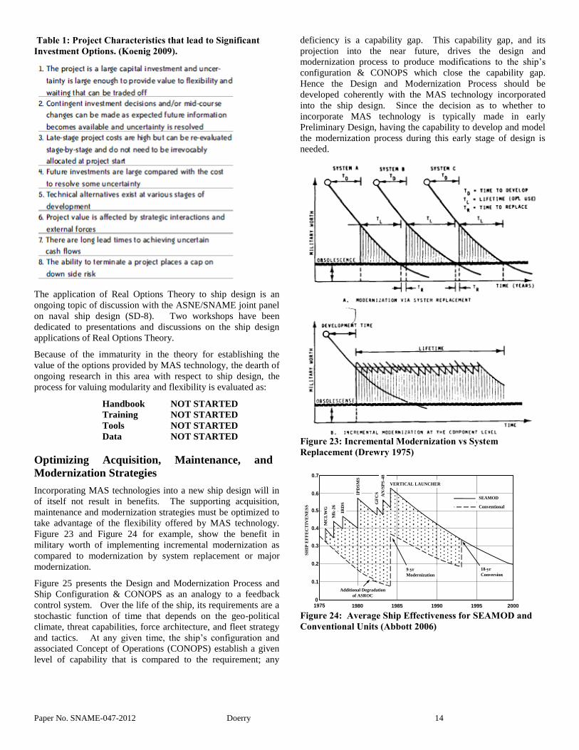
The FI Open Power is based either on a legacy connectorized
power panel (Figure 20) or on an Integrated Power Node Center
(IPNC) described in MIL-PRF-32272and by Ykema (2007).
(Figure 21)
While the remaining FI technologies (Open HVAC, data
cabling, and lighting) are based on COTS products and
technically mature, specifications and standards do not yet exist
for integration into a naval ship.
In designing a space using FI technologies, one of the
challenges is determining how much capacity distributed
systems should allocate to these spaces. How many amps
should the feeder cable to an IPNC be rated for? How many
IPNCs should be installed in a space? Formal guidance
approved by appropriate technical warrant holders for
developing answers to these and related questions do not
currently exist. As a step to developing such guidance, two
useful documents (Garver 2011 and Vasilakos 2011) have been
created that can guide ship design teams.
Paper No. SNAME-047-2012 Doerry 12
Figure 20: Connectorized Legacy Power Panel
Figure 21: FI Open Power with IPNC (Ykema 2007)
FI technologies are therefore evaluated as:
TRL 7 DONE
Industry DONE
Specification WORKING
Handbook WORKING
Cost WORKING
Value NOT STARTED
MODULAR ADAPTABLE SHIP PROCESSES
The following sections present four MAS processes and
evaluate them for process maturity. The evaluation will simply
assign one of the following to describe the work needed to
achieve the criteria:
- Done: The criteria has been met
- Working: Ongoing efforts are working to meet the
criteria, or the criteria has been partially fulfilled
- Not Started: No efforts are currently underway to
meet the criteria.
The four processes described here are those most critical to
institutionalizing MAS technologies.
Estimating Cost
Decisions as to whether or not to incorporate a technology into
an acquisition program usually are based on evaluations of cost,
risk, and benefit. Unfortunately, accurately estimating the cost
associated with MAS technologies has been challenging. These
challenges are not unique to MAS technologies and apply to
many new technologies as described by Bowers (2010). Most
cost models are based on correlations of design variables with
historical return cost data. These purely correlation-based
models are usually only accurate when presented with new
designs that are similar to the data used to create the
correlations. For shipboard systems, costs are typically
correlated with weight and size. These models will estimate that
the cost of implementing a technology that results in larger or
heavier equipment will rise; even if the technology (like MAS)
was developed to reduce cost. Some of the cost reduction
mechanisms for MAS technologies during ship construction are
detailed by Thompson (1982).
In making cost engineering decisions, correlation of cost data
alone is not sufficient. The underlying mechanism for the true
cost of the ship must be identified. An activity or process-based
cost modeling effort is needed. When an optimization
procedure is performed based on a correlation-based model, the
optimum solution will be for the model alone, and not
necessarily an optimum with respect to reality as represented by
the true underlying mechanisms. Within the shipbuilding
industry, The Product Oriented Design and Construction
(PODAC) Cost Model (Ennis 1997) (Trumbule 1999) is an
example of an activity-based cost model (NSRP 1996) that has
been implemented to support detail design and construction.
These models however, generally require a level of product and
production process detail that historically has not been available
during the early stages of ship design when the decisions as to
whether or not to incorporate MAS technologies are made.
Because of the limited availability of data currently produced in
early stage design, Garver (2010) proposes that traditional
weight based cost algorithms be augmented with algorithms that
are sensitive to process.
To incorporate activity-based cost modeling in concept and
preliminary design, the design organization must develop design

Paper No. SNAME-047-2012 Doerry 13
products not normally produced today. For example,
developing a notional build strategy that ties the physical
features of a ship concept to design and production activities
could provide the a better linkage between the underlying
mechanisms for cost and the physical attributes of the ship.
Only by modeling these underlying mechanisms can design
optimization methods be trusted to produce an optimal solution
in reality. This optimal solution reflects costs associated with
the initial design of a ship, modernization of that ship, and
modified repeat designs of future ships. Unfortunately,
methods, tools, and data to support such an early stage design
optimization process do not currently exist. Therefore,
estimating cost is evaluated as:
Handbook NOT STARTED
Training NOT STARTED
Tools NOT STARTED
Data NOT STARTED
Valuing Modularity and Flexibility
Traditionally, Net Present Value (NPV) has been used as the
principal tool in business case analysis. NPV however, is only
useful in discriminating among multiple choices if these choices
have the same value. Furthermore, traditional NPV techniques
rely on a system meeting a pre-specified set of requirements,
and cannot accommodate the ability to accommodate
uncertainty very well. MAS technologies however, promise to
better meet evolving uncertain requirements at less cost as
compared to a traditional system optimized for a specific set of
requirements. Summers (1997) recognized the value of
deferring decisions to the future. However, demonstrating this
benefit analytically has been challenging. Gregor (2003)
observed:
Current valuations in naval ship design tend to focus on valuing a
point designed product. Although there have been efforts to more
completely explore the design space for the optimal solution, the
optimal solution is based on a fixed set of requirements and
preferences. In addition, optimization infers certainty. There is no
way in the current system to value adding flexibility to the
design, since under certainty, flexibility has no value. Flexibility instead, has value, in situations with high uncertainty.
Lawson (1977) proposed that the effectiveness of a weapon
system can be modeled as an exponentially decaying curve
which has unity value at IOC and decays with a characteristic
half-life. (Figure 22) Weaknesses of this method include a lack
of a physical basis for why effectiveness should follow a decay
curve as well as the basis for establishing the half-life. For
example, it would seem that the effectiveness of a weapons
system would remain constant if an opponent is not developing
systems or tactics to counter our systems. In fact a weapon
system may gain effectiveness if other systems, such as
surveillance systems or command and control systems
synergistically improve our own forces ability to employ a given
weapon system.
Figure 22: System Effectiveness Decay Curves (Lawson
1977)
More recently, Real Options Theory has been proposed for
evaluating the value of MAS technologies. Real Options
Theory proposes to apply financial options and analysis
techniques to non-financial applications. As shown in Table 1,
ship acquisition programs are characteristic of projects that
benefit from investment options. MAS technologies provide
those options. Real Options theory projects the value of being
able to make decisions in the future when better information is
available to make a better decision. Gregor (2003), Koenig
(2009) and Page (2011) provide good insights in the benefits
and limitations of applying real options theory to naval ship
acquisitions. While financial options are grounded in accepted
theory, more theoretical work is needed to develop analytically
rigorous methods to apply real options theory to ship design.
The inability to formally apply Real Options theory however,
does not preclude applying “Options Thinking” to develop
acquisition arguments to better value flexibility. As described
by Gregor (2003):
For managing technology projects, much of the analysis lies in
determining when and how to implement options. This analysis
is broken into three phases: discovery, selection, and monitoring.
In these ways, real options seek opportunities to build flexibility
into designs, evaluate the possibilities, and implement the best
ones, without being required to do so.
Paper No. SNAME-047-2012 Doerry 14
Table 1: Project Characteristics that lead to Significant
Investment Options. (Koenig 2009).
The application of Real Options Theory to ship design is an
ongoing topic of discussion with the ASNE/SNAME joint panel
on naval ship design (SD-8). Two workshops have been
dedicated to presentations and discussions on the ship design
applications of Real Options Theory.
Because of the immaturity in the theory for establishing the
value of the options provided by MAS technology, the dearth of
ongoing research in this area with respect to ship design, the
process for valuing modularity and flexibility is evaluated as:
Handbook NOT STARTED
Training NOT STARTED
Tools NOT STARTED
Data NOT STARTED
Optimizing Acquisition, Maintenance, and
Modernization Strategies
Incorporating MAS technologies into a new ship design will in
of itself not result in benefits. The supporting acquisition,
maintenance and modernization strategies must be optimized to
take advantage of the flexibility offered by MAS technology.
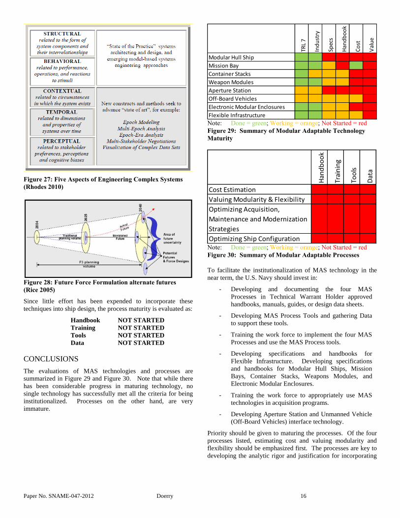
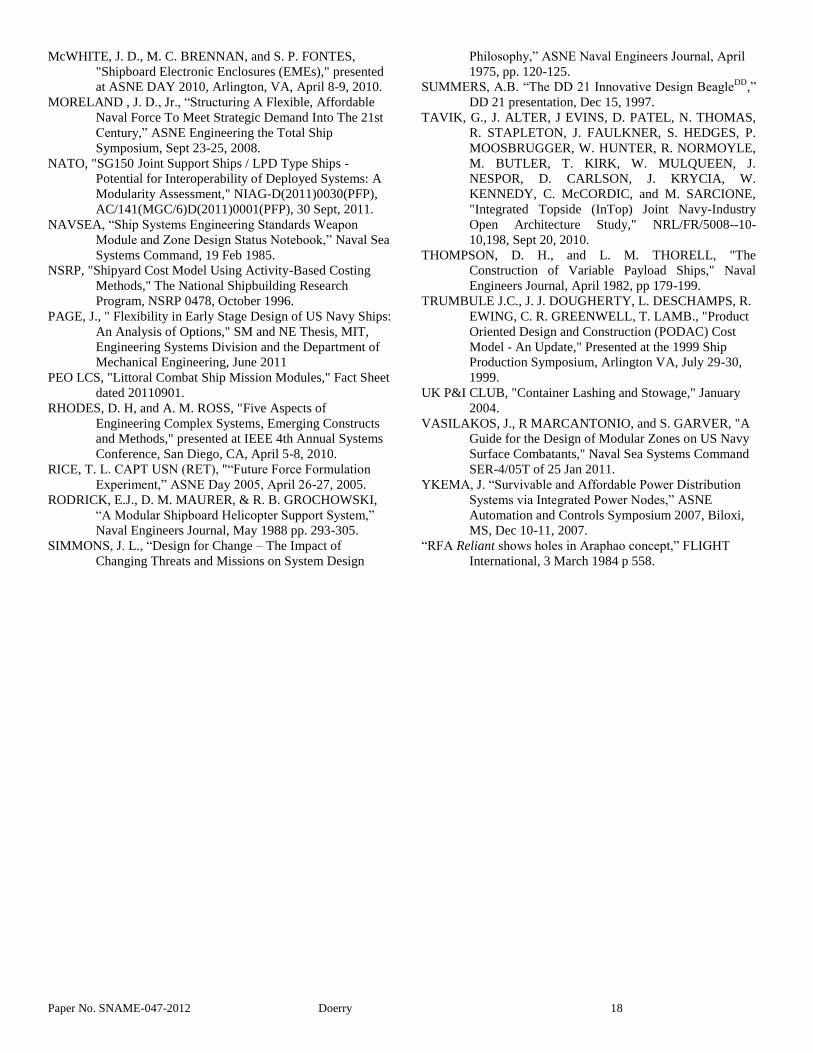
Figure 23 and Figure 24 for example, show the benefit in
military worth of implementing incremental modernization as
compared to modernization by system replacement or major
modernization.
Figure 25 presents the Design and Modernization Process and
Ship Configuration & CONOPS as an analogy to a feedback
control system. Over the life of the ship, its requirements are a
stochastic function of time that depends on the geo-political
climate, threat capabilities, force architecture, and fleet strategy
and tactics. At any given time, the ship’s configuration and
associated Concept of Operations (CONOPS) establish a given
level of capability that is compared to the requirement; any
deficiency is a capability gap. This capability gap, and its
projection into the near future, drives the design and
modernization process to produce modifications to the ship’s
configuration & CONOPS which close the capability gap.
Hence the Design and Modernization Process should be
developed coherently with the MAS technology incorporated
into the ship design. Since the decision as to whether to
incorporate MAS technology is typically made in early
Preliminary Design, having the capability to develop and model
the modernization process during this early stage of design is
needed.
Figure 23: Incremental Modernization vs System
Replacement (Drewry 1975)
AVERAGE SHIP EFFECTIVENESS
FOR SEAMOD AND
CONVENTIONAL UNITS
0.7
0.6
0.5
0.4
0.3
0.2
0.1
01975 1980 1985 1990 1995 2000
MC
LW
G
Mk
-26
IRD
S
IPD
SM
S
GF
CS
VERTICAL LAUNCHER
18-yr
Conversion
9-yr
Modernization
Additional Degradation
of ASROC
AN
/SP
S-4
8
SEAMOD
Conventional
SH
IP E
FF
EC
TIV
EN
ES
S
FIG 12
Figure 24: Average Ship Effectiveness for SEAMOD and
Conventional Units (Abbott 2006)

Paper No. SNAME-047-2012 Doerry 15
Design and
Modernization
Process
+
-
Ship
Configuration
& CONOPS
Ship Capability
Ship Requirement(stochastic function of time)
Capability Gap
Flexibility Goal: Minimize Acquisition and Modernization Costwhile also minimizing positive Capability Gap during the design service life.
Ship Design &ModernizationSpecifications
Ship Requirement function of:-- Threat Evolution
-- Fleet Composition-- Fleet Strategy and Tactics
Consider the Design and Modernization Process as a MIMO controller for the Ship
Configuration & CONOPS. The latter must provide sufficient “control authority” or
“control bandwidth” to provide acceptable performance.
Figure 25: Design and Modernization Process as part of a
feedback control loop.
Page (2011) modeled Figure 25 for two different sets of Design
and Modernization Processes and Ship Configurations. The
first, inflexible, set consists of a ship design without significant
MAS technologies and a modernization strategy based on small
annual investments and a large mid-life upgrade. The second,
flexible, set in contrast features many of the MAS technologies
and spreads the total modernization funds and effort evenly
across all the years in the ship’s service life. Page used a
Monte-Carlo simulation to determine the ability of each set to
respond to the stochastic capability gap. As shown in Figure 26,
the flexible set consistently performed better in meeting the
stochastic requirement than the inflexible set.
Figure 26: Cumulative Distributions of Capability Gaps
(Page 2011)
In developing his model, Page made a number of assumptions
that would have to be verified or modified to use in an actual
ship design process. As compared to the decay curves proposed
by Lawson, this method promises to better model the military
value of MAS technology and its associated design and
modernization processes in the face of changing and uncertain
requirements.
Because modeling design and modernization processes are not
currently part of the ship design process, the process maturity is
evaluated as:
Handbook NOT STARTED
Training NOT STARTED
Tools NOT STARTED
Data NOT STARTED
Optimizing Ship Configuration
If the design and modernization process are viewed as a control
system (Figure 25), then the MAS features incorporated into the
design provide the “control authority” for being able to react to
the uncertain and changing requirements. Incorporating MAS
technology typically requires an investment up front to enable
options that can be exercised in the future. The question then
becomes: how much of which MAS technologies should
optimally be incorporated into a ship design? Investing too
much could result in excess flexibility that is likely not to be
used over the ship’s service life. Likewise, investing too little
could result in excessive modernization costs, or the ship
retiring before the end of its design service-life. The modeling
methods proposed and demonstrated by Page (2011) are likely a
good starting point for developing the theory and tools for
optimizing ship configurations with respect to the amount and
type of MAS technologies.
One approach to addressing how to incorporate MAS
technologies into ship design is suggested by Rhodes and Ross
(2010). As shown in Figure 27, state of the practice in complex
system design, including ship design, addresses the structural
and behavioral aspects of the ship. Rhodes and Ross propose
that these aspects be augmented with Contextual, Temporal, and
Perceptual aspects as well. The MAS technologies directly
address the ship's Temporal opportunities. Rhodes and Ross
refer to Epoch and Multi-Epoch modeling to address the
changing properties of the contextual aspects. Within the naval
engineering community, this type of modeling has been
incorporated into Future Force Formulation (Rice 2005,
Moreland 2008, and Doerry 2009). In Future Force
Formulation, alternate futures are postulated. A ship concept
can be evaluated for each alternate future in terms of how
affordably modifications can be made to its configuration to
meet its allocated force requirements. A good design will be
adaptable and affordable across the range of likely alternate
futures.
Paper No. SNAME-047-2012 Doerry 16
Figure 27: Five Aspects of Engineering Complex Systems
(Rhodes 2010)
Figure 28: Future Force Formulation alternate futures
(Rice 2005)
Since little effort has been expended to incorporate these
techniques into ship design, the process maturity is evaluated as:
Handbook NOT STARTED
Training NOT STARTED
Tools NOT STARTED
Data NOT STARTED
CONCLUSIONS
The evaluations of MAS technologies and processes are
summarized in Figure 29 and Figure 30. Note that while there
has been considerable progress in maturing technology, no
single technology has successfully met all the criteria for being
institutionalized. Processes on the other hand, are very
immature.
TRL
7
Ind
ust
ry
Spec
s
Han
db
oo
k
Co
st
Val
ue
Modular Hull Ship
Mission Bay
Container Stacks
Weapon Modules
Aperture Station
Off-Board Vehicles
Electronic Modular Enclosures
Flexible Infrastructure Note: Done = green; Working = orange; Not Started = red
Figure 29: Summary of Modular Adaptable Technology
Maturity
Han
db
oo
k
Trai
nin
g
Too
ls
Dat
a
Cost Estimation
Valuing Modularity & Flexibility
Optimizing Acquisition,
Maintenance and Modernization
Strategies
Optimizing Ship Configuration Note: Done = green; Working = orange; Not Started = red
Figure 30: Summary of Modular Adaptable Processes
To facilitate the institutionalization of MAS technology in the
near term, the U.S. Navy should invest in:
- Developing and documenting the four MAS
Processes in Technical Warrant Holder approved
handbooks, manuals, guides, or design data sheets.
- Developing MAS Process Tools and gathering Data
to support these tools.
- Training the work force to implement the four MAS
Processes and use the MAS Process tools.
- Developing specifications and handbooks for
Flexible Infrastructure. Developing specifications
and handbooks for Modular Hull Ships, Mission
Bays, Container Stacks, Weapons Modules, and
Electronic Modular Enclosures.
- Training the work force to appropriately use MAS
technologies in acquisition programs.
- Developing Aperture Station and Unmanned Vehicle
(Off-Board Vehicles) interface technology.
Priority should be given to maturing the processes. Of the four
processes listed, estimating cost and valuing modularity and
flexibility should be emphasized first. The processes are key to
developing the analytic rigor and justification for incorporating

Paper No. SNAME-047-2012 Doerry 17
MAS technology into a ship. Institutionalizing the more mature
MAS technologies should be the second priority. Of the mature
MAS technologies, Flexible Infrastructure should have the
highest priority since it is most easily retrofitted on existing
ships.
Finally, maturing the currently immature MAS technologies
should be pursued. Once the currently immature MAS
technologies have been matured, they too should be
institutionalized.
ACKNOWLEDGEMENTS
Many individuals have contributed material and spent
significant time reviewing and suggesting improvements to this
paper. I particularly thank Jack Abbott, Dave Helgerson,
Patrick Karvar, Kwok Eng, and Scott Littlefield for their
assistance.
REFERENCES
ABBOTT, J. W., “Modular Payload Ships in the U.S. Navy,”
Transactions, The Society of Naval Architects and
Marine Engineers, November 1977.
ABBOTT, J. “The SSES Program – Foresight and Hindsight,”
presentation, NKF Engineering Inc. Feb 17, 1994.
ABBOTT, J. W., R. DeVries, W. Schoenster and J. Vasilakos,
“The Impact of Evolutionary Acquisition on Naval
Ship Design,” Transactions, The Society of Naval
Architects and Marine Engineers , October 2003
ABBOTT, J. W., “Modular Payload Ships: 1975-2005,”
presented at the ASNE Engineering the Total Ship
Symposium, ETS 2006, May 1-2, 2006.
BERTRAM, V., "Modularization of Ships," Report within the
framework of Project "Intermodul" s/03/G
IntermareC, 28 July 2005.
BOWERS, D., A. CARDIEL, B. CURTIS, and S.
MONTRIEF, "Overcoming Cost Estimating
Challenges for Navy Combat Systems," presented at
ASNE Engineering the Total Ship (ETS) Symposium
2010, Falls Church, VA, July 14-15, 2010.
BROOME, G. W., D. W. NELSON, and W. D. TOOTLE,
"The Design of Variable Payload Ships," Naval
Engineers Journal, April 1982, pp 147-177.
CAMPONESCHI, E.T. and K. M. WILSON, "The Advanced
Enclosed Mast Sensor System: Changing U.S. Navy
Ship Topsides for the 21st Century," Carderock
Division, NSWC - Technical Digest, December
2001.
CHEUNG, P., A. LEVINE, R. MARCANTONIO, and J.
VASILAKOS, "Standard Process for the Design of
Modular Spaces," presented at ASNE Engineering
the Total Ship (ETS) Symposium 2010, Falls Church,
VA, July 14-15, 2010.
DEATON, W. A., and J. L. CONKLIN, "Developing
Reconfigurable Command Spaces for the Ford-Class
Aircraft Carriers," presented at ASNE Engineering
the Total Ship (ETS) Symposium 2010, Falls Church,
VA, July 14-15, 2010.
DEPARTMENT OF DEFENSE, "Technology Readiness
Assessment (TRA) Guidance," Assistant Secretary of
Defense for Research and Engineering (ASD(R&E)),
May 13, 2011.
DeVRIES, R., A. LEVINE, W. H. MISH JR., “Enabling
Affordable Ships through Physical Modular Open
Systems,” ASNE Engineering the Total Ship
Symposium 2008, Falls Church, VA., Sept 23-25,
2008.
DOERRY, N. H., "Institutionalizing the Electric Warship,"
ASNE Naval Engineers Journal, 2006, Vol. 118 No
4, pp 57-64.
DOERRY, N. H. and H. FIREMAN, "Fleet Capabilities Based
Assessment (CBA)," ASNE Naval Engineers Journal,
2009, Vol 121 No 4, pp. 107-116.
DREWRY, J. T., and O. P. JONS, "Modularity: Maximizing
the Return on the Navy's Investment," Naval
Engineers Journal, April 1975, pp 198-214
ENNIS, K. J., J. J. DOUGHERTY, T. LAMB, C. R.
GREENWELL, R. ZIMMERMANN, "Product-
Oriented Design and Construction Cost Model,"
presented at the 1997 Ship Production Symposium,
New Orleans, LA, April 21-23, 1997.
GALE, P. A., "Margins in Naval Surface Ship Design," ASNE
Naval Engineers Journal, April 1975 pp 174-188.
GARVER, S. N., and J EDYVANE, "Ship Modularity Cost-
Reduction Models," presented at ASNE Engineering
the Total Ship (ETS) Symposium 2010, Falls Church,
VA, July 14-15-2010.
GARVER, S., R. MARCANTONIO, and P. SIMS, "Modular
Adaptable Ship (MAS) Total Ship Design Guide for
Surface Combatant," Naval Sea Systems Command
SER 9/05T of 7 Feb 2011.
GREGOR, J.A., “Real Options for Naval Ship Design and
Acquisition: A Method for Valuing Flexibility under
Uncertainty,” S.M. Thesis, MIT Department of
Ocean Engineering, 2003.
INTERNATIONAL ORGANIZATION FOR
STANDARDIZATION (ISO), “Aircraft – Rail and
stud configuration for passenger equipment and cargo
restraint,” ISO 7166:1985.
JOLLIFF, J. V. "Modular Ship Design Concepts," Naval
Engineers Journal, October 1974 pp 11-30.
KOENIG, P., D. NALCHAJIAN, and J. HOOTMAN, "Ship
Service Life and Naval Force Structure," Naval
Engineers Journal, 121:1 (2009): 69-77.
KOENIG, P., “Real Options in Ship and Force Structure
Analysis: A Research Agenda,” ASNE Naval
Engineers Journal, 2009 #4, pp. 95-105.
LAWSON, C. E. "SEAMOD - A New Way to Design,
Construct, Modernize and Convert U.S. Navy
Combatant Ships," 14th Annual Technical Symposium,
Association of Scientists and Engineers of the Naval
Air and Sea Systems Command, March 1977.
LITTLEFIELD, S. “Tactical Expandable Maritime Platform
(TEMP) Development and Way Ahead Discussions,”
Presentation, DARPA 2012.
Paper No. SNAME-047-2012 Doerry 18
McWHITE, J. D., M. C. BRENNAN, and S. P. FONTES,
"Shipboard Electronic Enclosures (EMEs)," presented
at ASNE DAY 2010, Arlington, VA, April 8-9, 2010.
MORELAND , J. D., Jr., “Structuring A Flexible, Affordable
Naval Force To Meet Strategic Demand Into The 21st
Century,” ASNE Engineering the Total Ship
Symposium, Sept 23-25, 2008.
NATO, "SG150 Joint Support Ships / LPD Type Ships -
Potential for Interoperability of Deployed Systems: A
Modularity Assessment," NIAG-D(2011)0030(PFP),
AC/141(MGC/6)D(2011)0001(PFP), 30 Sept, 2011.
NAVSEA, “Ship Systems Engineering Standards Weapon
Module and Zone Design Status Notebook,” Naval Sea
Systems Command, 19 Feb 1985.
NSRP, "Shipyard Cost Model Using Activity-Based Costing
Methods," The National Shipbuilding Research
Program, NSRP 0478, October 1996.
PAGE, J., " Flexibility in Early Stage Design of US Navy Ships:
An Analysis of Options," SM and NE Thesis, MIT,
Engineering Systems Division and the Department of
Mechanical Engineering, June 2011
PEO LCS, "Littoral Combat Ship Mission Modules," Fact Sheet
dated 20110901.
RHODES, D. H, and A. M. ROSS, "Five Aspects of
Engineering Complex Systems, Emerging Constructs
and Methods," presented at IEEE 4th Annual Systems
Conference, San Diego, CA, April 5-8, 2010.
RICE, T. L. CAPT USN (RET), "“Future Force Formulation
Experiment,” ASNE Day 2005, April 26-27, 2005.
RODRICK, E.J., D. M. MAURER, & R. B. GROCHOWSKI,
“A Modular Shipboard Helicopter Support System,”
Naval Engineers Journal, May 1988 pp. 293-305.
SIMMONS, J. L., “Design for Change – The Impact of
Changing Threats and Missions on System Design
Philosophy,” ASNE Naval Engineers Journal, April
1975, pp. 120-125.
SUMMERS, A.B. “The DD 21 Innovative Design BeagleDD
,”
DD 21 presentation, Dec 15, 1997.
TAVIK, G., J. ALTER, J EVINS, D. PATEL, N. THOMAS,
R. STAPLETON, J. FAULKNER, S. HEDGES, P.
MOOSBRUGGER, W. HUNTER, R. NORMOYLE,
M. BUTLER, T. KIRK, W. MULQUEEN, J.
NESPOR, D. CARLSON, J. KRYCIA, W.
KENNEDY, C. McCORDIC, and M. SARCIONE,
"Integrated Topside (InTop) Joint Navy-Industry
Open Architecture Study," NRL/FR/5008--10-
10,198, Sept 20, 2010.
THOMPSON, D. H., and L. M. THORELL, "The
Construction of Variable Payload Ships," Naval
Engineers Journal, April 1982, pp 179-199.
TRUMBULE J.C., J. J. DOUGHERTY, L. DESCHAMPS, R.
EWING, C. R. GREENWELL, T. LAMB., "Product
Oriented Design and Construction (PODAC) Cost
Model - An Update," Presented at the 1999 Ship
Production Symposium, Arlington VA, July 29-30,
1999.
UK P&I CLUB, "Container Lashing and Stowage," January
2004.
VASILAKOS, J., R MARCANTONIO, and S. GARVER, "A
Guide for the Design of Modular Zones on US Navy
Surface Combatants," Naval Sea Systems Command
SER-4/05T of 25 Jan 2011.
YKEMA, J. “Survivable and Affordable Power Distribution
Systems via Integrated Power Nodes,” ASNE
Automation and Controls Symposium 2007, Biloxi,
MS, Dec 10-11, 2007.
“RFA Reliant shows holes in Araphao concept,” FLIGHT
International, 3 March 1984 p 558.