
Installing the UBX Truck Mounted Brake...
37
1 Installing the UBX Truck Installing the UBX Truck Mounted Brake Equipment Mounted Brake Equipment
Transcript of Installing the UBX Truck Mounted Brake...

1
Installing the UBX Truck Installing the UBX Truck Mounted Brake EquipmentMounted Brake Equipment

2
Features OverviewFeatures Overview• Light Weight ~ 775 lbs
• Meets AAR Requirements
• Based on the TMX platform for proven reliability
• Highly efficient design
• Maintains efficiency over time
• Easy to Install, Set-up, and Adjust
• Easy to read Piston Travel Indicator

3
UBX AssemblyUBX AssemblyThese are the main components that make up the UBX truck mounted brake. This diagram does not include brake beams and other truck components.

4
Exploded ViewExploded View
34
14
15
19
20
18 21
25
1122
13
24
27
3526
8
17
29
28
36
8
9
31
10B
10
10A
30
3
4
10C
32
2
5
12
37
7
6
1
16
23
33

5
Material Material ListList
This is a list of the parts, and part numbers required to assemble the UBX Truck Mounted Brake. The item numbers shown match the exploded view shown on slide 4.
ITEM NO. DESCRIPTION PART NUMBER W/HB QTY L/HB QTY
1 HB/Cyl. Trans. Lever Assembly TM-22001 1 02 Control Rod Pin 660420 1 13 1/2" Elastic Stop Nut 523190 1 14 Control Rod Nut 660421 1 15 Control Rod 660418 1 16 Non-HB/Cyl. Trans. Lever Assy. 661120 0 17 Transfer Pin 660413 1 18 14 degree UBX Brake Beam Assy. TM-22029 2 29 Transfer Pin 660413 1 1
10 Slack Adjuster Assembly 660416 1 110a Trigger Pin 660419 1 110b Locking Bolt 1 110c Trigger 660417 1 111 Return Push Rod Clevis 660415 1 112 Washer TM-22018 1 113 1-1/4” Lock Washer 576042 1 114 Transfer Pin 660413 1 115 1/2" Locknut - Grade 5 645002-0001 1 116 1/2 x 2-1/4" T-Head Bolt 593042 1 117 5/8" Locknut - Grade 5 645002 2 218 5/8" Hex Head Cap Screw 593006 2 219 10" Brake Actuator Assy. (LT – 4.50” PT) TM-22003-1 1 119 10" Brake Actuator Assy. (ST – 3.75” PT) TM-22003 1 120 Thimble Type Strainer 526835 1 121 Spring Pin 660497 1 122 1-1/4” Hex Jam Nut 660265 1 123 Transfer Pin 660413 1 124 Return Push Rod 660461 1 125 Anti-Rattle Ring 506401 1 126 Transfer Pin 660413 1 127 Return Push Rod Assembly 660414 1 128 Center Strut Pin 660411 1 129 Non-Cyl Trans Lever Assy./5.600 ratio 660494 0 129a Non-Cyl Trans Lever Assy. 660494-0002 1 130 1/8 x 1” Cotter Pin 593388 1 131 5/16 x 2-1/2" Cotter Pin 569145 1 132 3/16 x 1-1/2" Cotter Pin 94977 1 133 5/16 x 3" Cotter Pin 660554 1 134 5/16 x 2-1/2" Cotter Pin 569145 1 135 5/16 x 2-1/2" Cotter Pin 569145 1 136 5/16 x 3" Cotter Pin 660554 1 137 5/16 x 2-1/2" Cotter Pin 569145 1 1

6
Engineering SpecificationsEngineering Specifications
34,049 Lbs.31,779 Lbs.29,792
lbs.
High 16.13 Lever Ratio
Mid 15.06 Lever Ratio
Low 14.12 Lever Ratio
Hand Brake Output Force Per Truck @ 3,015 lbs. Input (70% Eff.)
13,681 Lbs.12,769 Lbs.11,971Lbs.2,850 lbs.220 cu.in.55 cu.in.4.50"10" Dia. Long Travel
16,321 Lbs.15,233 Lbs.14,281 Lbs.3,400 lbs.185 cu.in.55 cu.in.3.75"10" Dia. Short Travel
High 6.00 Lever Ratio
Mid 5.60 Lever Ratio
Low 5.25 Lever Ratio
Nominal Output Force @ 65psi
Displaced Volume
Clearance Volume
Nominal PTAssembly Description
Output Force Per Truck @ 80% Eff.Air Actuator
UBX Engineering Specification Information

7
TM-22036-3TM-22036-2Badgeplate Part Number
662580, I2662580, I2Installation Drawing Number
TM-22037TM-22037Car PT Decal Part Number
10.88% GRL / 13.54% HB11.61% GRL / 14.44% HBEst. Net Braking Ratio
662580, 1A662580, 1AAssembly Drawing Number
662580-0006662580-0008Non-HB Truckset Part Number
662580-0005662580-0007HB Truckset Part Number
220K / 8.5-13% NBRUBX Long Travel / 5.25 LR
•220K / 11-13% NBRUBX Long Travel / 5.60 LR
70 Ton
9.10% GRL / 11.33% HB8.93% GRL / 11.11% HBEst. Net Braking Ratio
TM-22033-1TM-22033-1Car PT Decal Part Number
TM-22067-3TM-22067-2Badgeplate Part Number
662580, I2662580, I2Installation Drawing Number
662580, 1A662580, 1AAssembly Drawing Number
662580-0006662580-0008Non-HB Truckset Part Number
662580-0005662580-0007HB Truckset Part Number
263K / 8.5-13% NBRUBX Long Travel / 5.25 LR
286K / 8.5-13% NBRUBX Long Travel / 5.60 LR
100 Ton
11.58% GRL / 12.08% HB11.41% GRL / 11.91% HBEst. Net Braking Ratio
TM-22033TM-22033Car PT Decal Part Number
TM-22032-2TM-22032-1Badgeplate Part Number
662580, I0662580, I0Installation Drawing Number
662580, 0A662580, 0AAssembly Drawing Number
662580-0004662580-0002Non-HB Truckset Part Number
662580-0003662580-0001HB Truckset Part Number
•263K / 11-13% NBRUBX Short Travel / 5.60 LR
•286K / 11-13% NBRUBX Short Travel / 6.00 LR
100 Ton
DescriptionDescription

8
Tools Needed to InstallTools Needed to Install
Before you begin the installation of the UBX, please make sure to have the following tools available:
• ¾” Combination wrench • ¾” Deep wall socket ½” drive
• ½” Drive ratchet • 1” Open-end wrench
• 2½” Pipe wrench • 15/16” Open-end wrench
• 15/16” Deep well socket ½” drive • 6” Extension ½” drive
• Pliers • Hammer

9
InstallationInstallation1. The UBX brake beams (8) are to be
installed during truck assembly normal to your existing shop practice. Install the end of the brake beam into the truck side frame as shown.
8
8

10
InstallationInstallation
Once the UBX brake beams (8) are installed, mount the brake actuator (19) to the brake beam prior to the truck final assembly. 19
8

11
InstallationInstallation
2. Please refer to your UBX assembly or installation drawings to determine which UBX equipment combination is being applied. The type of car and truck capacity will govern connection requirements on the assembly.

12
Mounting the Brake ActuatorMounting the Brake Actuator3. Mount the brake actuator (19) to the
brake beam (8). Align the two rear mounting holes of the brake actuator (19) with the two corresponding holes on the brake beam (8). Align the one side-mounting hole of the brake actuator (19) to the one corresponding hole on the strut side-pad. The brake actuator will be facing outboard from the bolster. Using two 5/8” hex bolts (18) through the topside of the compression member, fasten the rear-mounting portion of the brake actuator (19) with the two 5/8” hex locknuts (17); do not tighten at this time.
18
18
19
8

13
Mounting the Brake ActuatorMounting the Brake ActuatorUsing a ½” T-head bolt (16) from the underside of the center strut pad, fasten the side mounting with a ½”hex locknut (15). Tighten and torque the two 5/8” hex locknuts (17 on previous slide) to 110 ft-lbs. (150 Nm) and the ½” hex locknut (15) to 85 ft-lbs (115 Nm).
CAUTION: When tightening or applying torque to any UBX fasteners, always use a mechanical mean; adjustable wrench, box end wrench, socket, etc. To avoid personal injury, DO NOT MANUALLY HOLD FASTENERS!
15
16

14
Installing the Transfer LeverInstalling the Transfer Lever4. On trucks without handbrake
connections, install Non-HB/cyltransfer lever assembly (6) to the brake actuator brake beam. Insert lever (6) through the slot in the brake beam strut from the brake actuator side. Secure lever (6) with transfer pin (14) through the brake actuator push rod clevis. Secure lever (6) to the brake beam strut with the center strut pin (23).
6
14
23

15
Installing the Transfer LeverInstalling the Transfer Lever
For hand-braked trucks, install the washer (12) between the topside of lever (1) and the strut lever slot opening. For hand-braked trucks, install HB/cyl transfer lever (1) to the brake actuator brake beam. Secure lever (1) to the brake beam strut with the center strut pin (23).
NOTE: It may be necessary to overcome some slight actuator bail or angularity to insert the center strut pin.
12
23
1

16
Install Slack AdjusterInstall Slack Adjuster5. Insert the slack adjuster (10) through the bolster window with the
trigger end jaw of the slack adjuster toward the actuator brake beam. Cut the plastic shipping strap from the slack adjuster front jaw.
10

17
Install Transfer LeverInstall Transfer Lever6. Install transfer lever (29) to the non-actuator brake beam. The transfer
lever (29) will determine your lever ratio. Insert transfer lever (29) through the slot in the brake beam strut from the return push rod side. Align the center hole of transfer lever (29) with the strut hole and pin to the strut with the center strut pin (28). Install clevis pin to transfer lever.
29
10

18
Badge PlateBadge PlateRefer to the car badge plate, ask your air brake supervisor, or look at the installation drawings to determine which side of the transfer lever (29) is located toward the slack adjuster (10).
19
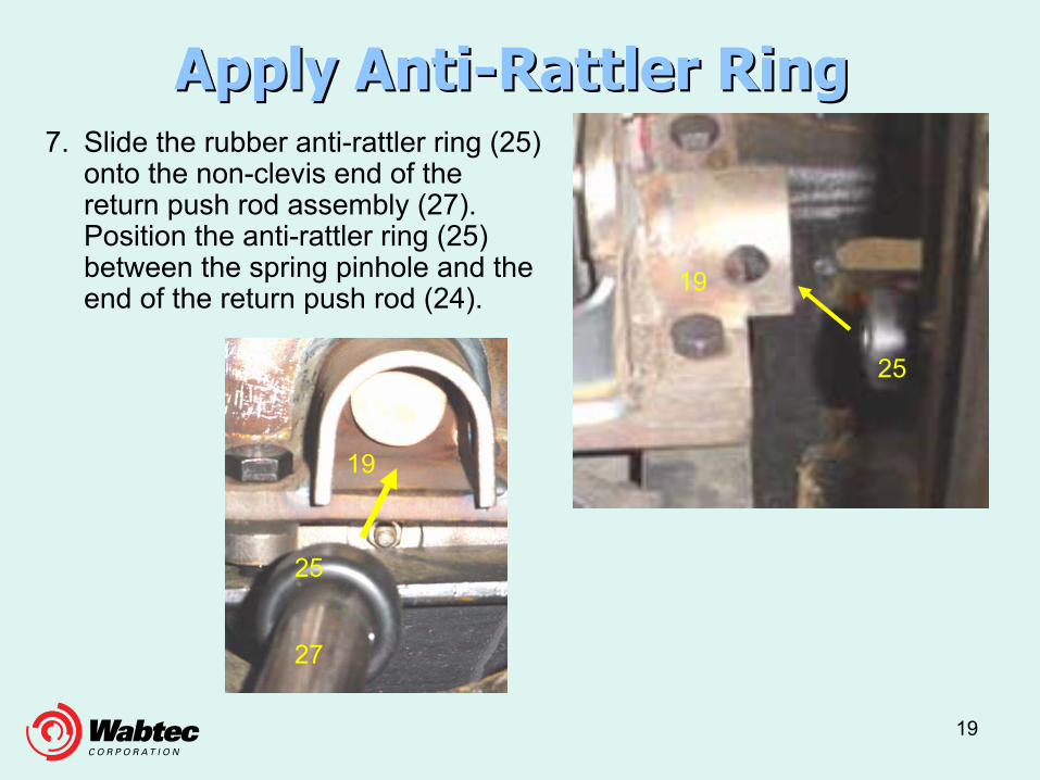
Apply AntiApply Anti--Rattler RingRattler Ring7. Slide the rubber anti-rattler ring (25)
onto the non-clevis end of the return push rod assembly (27). Position the anti-rattler ring (25) between the spring pinhole and the end of the return push rod (24).
25
19
25
27
19

20
Apply Return Push RodApply Return Push RodInsert this end of the return push rod assembly (27) through the bolster window and into the rear of the brake actuator (19). Ensure that the anti-rattler ring is between the spring pinhole and the actuator body. Line up the pinhole on the return push rod assembly (27) with the spring pinhole on the brake actuator bracket. Align the return push rod clevis hole to the transfer lever (29) hole and secure with transfer pin (26) (opposite end of rod). 27
19
2629
27

21
Align Transfer LeverAlign Transfer Lever8. Align transfer lever (29)
with the proper slack adjuster rack end jaw hole and secure with a transfer pin (9).
100 ton trucks
70 ton trucks
NOTE: Refer to the proper UBX installation or assembly drawing or ask your air brake supervisor for the correct pinning of transfer lever (29) to the inner or outer hole of the slack adjuster rear jaw. (See Badge Plate, Slide 15)
9
9

22
Setting the Slack AdjusterSetting the Slack Adjuster
Insert trigger (10C) into the trigger end jaw slot of the slack adjuster (10) from the brake actuator side. Next, slide the slack adjuster control rod (5) into the trigger (10C). Both the slack adjuster (10) and the control rod (5) should be set onto the transfer lever (6 or 1) simultaneously. Insert the trigger pin (10A) through the trigger pinhole on the slack adjuster (10).
10C
10
5
10A

23
Setting the Slack AdjusterSetting the Slack Adjuster
Secure the slack adjuster (10) to transfer lever (6 or 1) with transfer pin (7). Insert the control rod pin (2) through the control rod clevis and the small hole of transfer lever (6 or 1). Turn the spherical flanged sleeved nut (4) clockwise onto the control rod (5) with the sleeved side toward the trigger of the slack adjuster until a ¼” gap is left between the nut and the trigger. Attach 1/2:”elastic stop nut (3) to control rod.
10
2
4
7
5
10c
3

24
Setting the Slack AdjusterSetting the Slack Adjuster9. Remove the slack adjuster locking
bolt (10B).
10B
10C
(See Figure 1 and the Service Bulletin 2000-02)
CAUTION: Do not bump the slack adjuster trigger (10C).
If bumped, the slack adjuster could activate and sudden let-out of the rack extension could occur at the rear jaw.

25
Install Brake ShoesInstall Brake Shoes10. Install the 2” brake shoes and shim the
outboard side of all journal bearings using 1/8” shims to prevent outward wheel and axle movement.
26
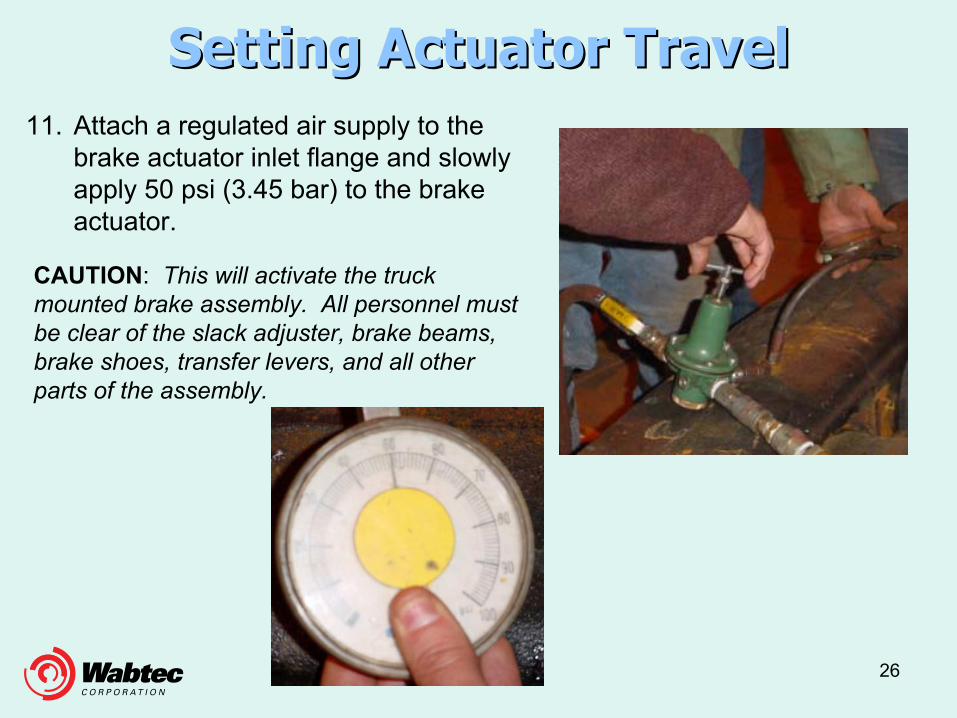
Setting Actuator TravelSetting Actuator Travel11. Attach a regulated air supply to the
brake actuator inlet flange and slowly apply 50 psi (3.45 bar) to the brake actuator.
CAUTION: This will activate the truck mounted brake assembly. All personnel must be clear of the slack adjuster, brake beams, brake shoes, transfer levers, and all other parts of the assembly.

27
Setting ActuatorSetting Actuator
12. Release the brake assembly and reapply 50 psi (3.45 bar) to the brake actuator. Reapply 54 psi (3.72 bar) to the brake actuator for European applications. For short piston travel applications, a measurement of 3-3/4” ± ¼”(95 ± 6mm) should be taken to achieve the desired piston travel. For long piston travel applications, a measurement of 4-1/2” ± ¼” (114 ± 6mm) should be taken to achieve the desired piston travel.

28
Setting Actuator TravelSetting Actuator Travel
Refer to the car badge plate, ask your air brake supervisor, or look at the installation drawings to determine the proper piston travel application. On brake applications, travel indicator should be in the opening as required by the badge plate.
Optimum Piston Travel Setting Range

29
Setting Actuator TravelSetting Actuator TravelIf piston travel is long, turn the spherical flanged sleeved nut (4) clockwise. If piston travel is short, turn the spherical flanged sleeved nut (4) counterclockwise. There is a 1 to 2 adjustment ratio from spherical flanged sleeved nut travel to piston travel. When the required piston travel is met and repeatable, turn the ½”locknut (3) clockwise against the spherical flanged sleeved nut (4) and torque against each other to 55 ft-lbs. (75 Nm).
34

30
Setting Adjuster RackSetting Adjuster Rack13. With air applied, measure
and record the slack adjuster rack, the distance between the rear jaw of the slack adjuster and the rear of the housing. The slack adjuster rack should be 1¼”(32mm) to 1¾” (44mm) (if measured from the inside of the cap to the rear jaw) or ¼” (6mm) to ¾” (19mm) (if measured from the edge of the cap to the rear jaw). Refer to Service Bulletin 2000-02 for details.
NOTE: This adjustment dimension can only be used on a truck with new wheels and new shoes.

31
Setting Adjuster RackSetting Adjuster RackIf the rack is too short, release the brakes and shorten the return push rod assembly by turning the return push rod (24) counterclockwise if facing the back of the brake actuator. If the rack is too long, release the brakes and lengthen the return push rod assembly by turning the return push rod (24) clockwise if facing the back of the brake actuator. There is approximately a 1 to 1 adjustment ratio from return push rod clevis travel to slack adjuster rack extension.

32
Setting Return Push RodSetting Return Push RodWhen the required slack adjuster rack is met and repeatable, align the hole in the return push rod (24) with the hole in the brake actuator bracket and insert the spring pin (21). Tighten the hex jam nut (22) on the return push rod (24) until the lock washer (13) is closed against the return push rod clevis (11).
22
13
11
24
2119

33
SetSet--up Procedure for Existing Cars in up Procedure for Existing Cars in Field Service or RetrofitsField Service or Retrofits
When installing UBX on cars with worn shoes and worn single wearwheels, Wabtec recommends the following procedures;
1. Install new wheels and new shoes on the first car, this is the template for the remainder of the cars in the series.
2. Adjust Slack Adjuster rack to the maximum 3/4” setup measurement, reference previous slides.
3. Once rack is set, measure length of Return Push Rod, take measurement from Spring Pin to middle of Push Rod Brake Pin center hole.
4. Use this measurement to set rod length on all successive trucks.5. Rack on subsequent trucks may vary. Setup piston travel for each
truck individually, as indicated on previous slides.
NOTE: This setup is only good for 1W wheels. On 2W and MW wheelscontact your Cardwell Westinghouse Representative.

34
Remove ShimsRemove Shims
14. Remove the shims from the outside of all the journal bearings.

35
Apply Cotter KeysApply Cotter Keys
15. Using cotter pins (30 thru 37), cotter all 8 remaining brake pin connections and verify the actuator piston travel and slack adjuster rack with trucks installed under the car body. Make any necessary adjustments.

36
Attach Air HoseAttach Air Hose
16. Ensure that the thimble type strainer (20) is installed in the brake actuator air inlet flange prior to attaching the car brake cylinder hose.
13

37
SummarySummary
This presentation was put together to ensure the UBX Truck Mounted Brake Assembly is assembled to the specifications of the Wabtec Corporation. All railroad safety standards must be applied to ensure against personal injury.
Wabtec would like to thank the workers at Kasgro car building facility in New Castle, PA for their help and participation on the slides used in this presentation.
Michael ZenertWabtec Global Services


![Adobe Photoshop PDF...FYXYYa cb`]bY UhAcggVYf["Wca#A7%gWCZZYf Mci k]`` bYYX mcif ghcfY gU`Yg fYWY]dh UbX [ib Vcl YbX dUbY` `UVY` k\]W\ X]gd`Umg h\Y dfcXiWh gYf]U` biaVYf UbX G?I biaVYf](https://static.fdocuments.in/doc/165x107/5e6c9615b8a5d071324f44f5/adobe-photoshop-pdf-fyxyya-cbby-uhacggvyfwcaa7gwczzyf-mci-k-byyx.jpg)