Installing the Router
22
CHAPTER 3-1 Cisco 2600 Series Routers Hardware Installation Guide OL-2171-02 3 Installing the Router This chapter guides you through the installation of the Cisco 2600 series routers and includes the following sections: • Required Tools and Equipment, page 3-1 • Setting Up the Chassis, page 3-2 • Connecting the DC Power Supply, page 3-12 • Power on the Router, page 3-17 • Connecting to a Network, page 3-17 • Connecting the Console Terminal and Modem, page 3-20 • What to Do After Installing Router Hardware, page 3-22 Warning Only trained and qualified personnel should be allowed to install or replace this equipment. To see translations of the warnings that appear in this publication, refer to the Regulatory Compliance and Safety Information document that accompanied this device. Required Tools and Equipment Installation might require some tools and equipment that are not provided as standard equipment with the router. Following are the tools and parts required for a typical router installation: • Number 2 Phillips screwdriver. • Flat-blade screwdrivers: small, 3/16-in. (0.476 cm) and medium, 1/4-in. (0.625 cm). • Electrostatic discharge (ESD)-preventive wrist strap. • Screws to secure the rack-mount brackets to the router. • Grounding lug with attaching screws. • Cables for connecting a PC or modem to the router (included). • Cables for connection to the WAN and LAN ports (dependent on configuration): – Ethernet 10BASE-T cable for connection to an Ethernet port (included). – Ethernet 100BASE-T cable for connection to a Fast Ethernet port (included). – Token Ring lobe cable for connection to the Token Ring port (included).
Transcript of Installing the Router

Cisco 2600 Series OL-2171-02
C H A P T E R 3
e
t with
Installing the Router
This chapter guides you through the installation of the Cisco 2600 series routers and includes thfollowing sections:
• Required Tools and Equipment, page 3-1
• Setting Up the Chassis, page 3-2
• Connecting the DC Power Supply, page 3-12
• Power on the Router, page 3-17
• Connecting to a Network, page 3-17
• Connecting the Console Terminal and Modem, page 3-20
• What to Do After Installing Router Hardware, page 3-22
Warning Only trained and qualified personnel should be allowed to install or replace this equipment. To seetranslations of the warnings that appear in this publication, refer to the Regulatory Complianceand Safety Information document that accompanied this device.
Required Tools and EquipmentInstallation might require some tools and equipment that are not provided as standard equipmenthe router. Following are the tools and parts required for a typical router installation:
• Number 2 Phillips screwdriver.
• Flat-blade screwdrivers: small, 3/16-in. (0.476 cm) and medium, 1/4-in. (0.625 cm).
• Electrostatic discharge (ESD)-preventive wrist strap.
• Screws to secure the rack-mount brackets to the router.
• Grounding lug with attaching screws.
• Cables for connecting a PC or modem to the router (included).
• Cables for connection to the WAN and LAN ports (dependent on configuration):
– Ethernet 10BASE-T cable for connection to an Ethernet port (included).
– Ethernet 100BASE-T cable for connection to a Fast Ethernet port (included).
– Token Ring lobe cable for connection to the Token Ring port (included).
3-1Routers Hardware Installation Guide

Chapter 3 Installing the RouterSetting Up the Chassis
N)
for the
Useows:
ps to
Note For more information on cable specifications, refer to the online documentCisco Modular AccessRouter Cabling Specifications on the Documentation CD-ROM that accompanied your routerpackage and on Cisco.com. For cable ordering information, see“Obtaining Technical Assistance”.
• Ethernet 10BASE-T hub or PC with a network interface card for connection to the Ethernet (LAport(s).
• Console terminal (an ASCII terminal or a PC running terminal emulation software) configured9600 baud, 8 data bits, no parity, and 2 stop bits. A terminal is required unless you are usingAutoInstall procedure. See the“Connecting the Console Terminal and Modem” section onpage 3-20 for instructions on connecting a console terminal.
• Modem for connection to the auxiliary port for remote administrative access. (Optional)
Setting Up the ChassisYou can set the chassis on a desktop, install it in a rack, or mount it on a wall or other flat surface.the procedure in this section that best meets the needs of your network. The sections are as foll
• Setting the Chassis on a Desktop, page 3-2
• Mounting the Chassis in a Rack, page 3-4
• Mounting the Chassis on the Wall, page 3-10
Cisco 2600 series routers include the following models:
• Cisco 2610 and Cisco 2610XM
• Cisco 2611 and Cisco 2611XM
• Cisco 2612 and Cisco 2613
• Cisco 2620 and Cisco 2620XM
• Cisco 2621 and Cisco 2621XM
• Cisco 2650 and Cisco 2650XM
• Cisco 2651 and Cisco 2651XM
• Cisco 2691
Setting the Chassis on a DesktopBefore setting the router on a desktop, shelf, or other flat, secure surface, perform the following steinstall the rubber feet:
Step 1 Locate the rubber feet on the black adhesive strip that shipped with the chassis. (SeeFigure 3-1.)
3-2Cisco 2600 Series Routers Hardware Installation Guide
OL-2171-02

Chapter 3 Installing the RouterSetting Up the Chassis
e five
Figure 3-1 Identifying the Rubber Feet
Step 2 Place the router upside down on a smooth, flat surface.
Step 3 Peel off the rubber feet from the black adhesive strip and place them adhesive-side down onto thround, recessed areas on the bottom of the chassis. (SeeFigure 3-2 andFigure 3-3.)
Figure 3-2 Rubber Feet Location on Cisco 261x, Cisco 262x, Cisco 26xxXM, and Cisco 265x SeriesRouters
Rubber feet (5)
Black adhesive strip
H47
96
Fan
H47
95
3-3Cisco 2600 Series Routers Hardware Installation Guide
OL-2171-02

Chapter 3 Installing the RouterSetting Up the Chassis
n
with aourassis
wn in
ent
Figure 3-3 Rubber Feet Location on Cisco 2691 Router
Step 4 Place the router right-side up on a flat, smooth, secure surface.
Caution Do not place anything on top of the router that weighs more than 10 lb (4.5 kg). Excessive weight otop could damage the chassis.
Mounting the Chassis in a RackThis section describes the procedures for rack-mounting the chassis. Cisco 2600 series routers chassis height of 1 rack-unit (1RU) ship with brackets for use with a 19-inch rack or, if specified in yorder, optional larger brackets for use with a 23- or 24-inch rack. Cisco 2600 series routers with a chheight of 2 rack-units (2RU) ship with brackets for use with a 19-inch rack. The brackets are shoFigure 3-4 andFigure 3-5.
Warning To prevent bodily injury when mounting or servicing this unit in a rack, you must take specialprecautions to ensure that the system remains stable. To see translations of the warnings thatappear in this publication, refer to the Regulatory Compliance and Safety Information documentthat accompanied this device. The following guidelines are provided to ensure your safety:
• If the rack contains only one unit, mount the unit at the bottom of the rack.
• If the rack is partially filled, load the rack from the bottom to the top, with the heaviest componat the bottom of the rack.
7209
9
Chassis bottom
3-4Cisco 2600 Series Routers Hardware Installation Guide
OL-2171-02

Chapter 3 Installing the RouterSetting Up the Chassis
unit
e
re
• If the rack contains stabilizing devices, install the stabilizers before mounting or servicing thein the rack.
Figure 3-4 Brackets for Cisco 261x, Cisco 262x, Cisco 26xxXM, and Cisco 265x Series Routers
Figure 3-5 Brackets for Cisco 2691 Router
Attaching the Brackets to Cisco 261x, Cisco 262x, Cisco 26xxXM, and Cisco 265x Series Routers
To install the chassis in a rack, attach the brackets in one of the following ways:
• With the front panel forward (seeFigure 3-6 andFigure 3-7)
• With the rear panel forward (seeFigure 3-8 andFigure 3-9)
• In a center-mount rack, with the rear panel forward (seeFigure 3-10 throughFigure 3-12)
Note Use the screws that came with your router package for attaching the brackets.
Note If you are installing a Cisco 2600 series router in a 19-inch rack with a 17.5-inch opening, orient thrack-mount brackets so that, when installed, they do not increase the width of the chassis. (SeeFigure 3-6.)
If you are installing a Cisco 2600 series router in a 19-inch rack with a 17.75-inch opening or a 23- o24-inch rack, orient the rack-mount brackets so that, when installed, they increase the width of thchassis. (SeeFigure 3-7.)
Bracket for use with a23-inch or 24-inch rack
Bracket for usewith a 19-inch rack 27
711
Narrow bracket forchassis side opposite fans
Wide bracket forchassis side with fans
Slots forcable tie
attachment
6028
9
LE
FT
RIG
HT
3-5Cisco 2600 Series Routers Hardware Installation Guide
OL-2171-02

Chapter 3 Installing the RouterSetting Up the Chassis
d
Note The following illustrations show how to connect the bracket to one side of the chassis. The seconbracket connects to the opposite side of the chassis.Figure 3-6 Bracket Installation—Front Panel Forward (19-Inch Rack with a 17.5-Inch Opening)
Note When installed in a 19-inch rack with a 17.75-inch opening, the Cisco 2600 series routers willprotrude beyond the front of the rack.
Figure 3-7 Bracket Installation—Front Panel Forward (19-Inch Rack with a 17.75-Inch Opening or a23- or 24-Inch Rack)
6267
6
Note: The second bracket attaches to the other side of the chassis.
6288
1Note: The second bracket attaches
to the other side of the chassis. Brackets for19-inch rack Brackets for
23-inch or 24-inch rack
3-6Cisco 2600 Series Routers Hardware Installation Guide
OL-2171-02

Chapter 3 Installing the RouterSetting Up the Chassis
Figure 3-8 Bracket Installation—Rear Panel Forward (19-Inch Rack with a 17.5-Inch Opening)
Figure 3-9 Bracket Installation—Rear Panel Forward (19-Inch Rack with a 17.75-Inch Opening or a23- or 24-Inch Rack)
7201
3
Note: The second bracket attaches to the other side of the chassis.
Brackets for19-inch rack
110V
60
Hz
1.6A
MAX
7201
4
Note: The second bracket attaches to the other side of the chassis.
110V
60
Hz
1.6A
MAX
Brackets for19-inch rack Brackets for
23-inch or 24-inch rack
3-7Cisco 2600 Series Routers Hardware Installation Guide
OL-2171-02

Chapter 3 Installing the RouterSetting Up the Chassis
Figure 3-10 Center-Mount Bracket Installation—Rear Panel Forward (19-Inch Rack with a 17.75-InchOpening or a 23- or 24-Inch Rack)
Figure 3-11 Center-Mount Bracket Installation—Rear Panel Forward (19-Inch Rack with a 17.5-InchOpening or a 23- or 24-Inch Rack)
Figure 3-12 Center-Mount Bracket Installation—Front Panel Forward (19-Inch Rack with a 17.5-InchOpening or a 23- or 24-Inch Rack)
7201
5
Note: The second bracket attaches to the other side of the chassis.
110V
60
Hz
1.6A
MAX
Brackets for19-inch rack Brackets for
23-inch or 24-inch rack
6298
3
Note: The second bracket attaches to the other side of the chassis.
Brackets for19-inch rack
Brackets for23-inch or 24-inch rack
110V
60
Hz
1.6A
MAX
7201
6Note: The second bracket attaches to the other side of the chassis.
Brackets for19-inch rack
Brackets for23-inch or 24-inch rack
3-8Cisco 2600 Series Routers Hardware Installation Guide
OL-2171-02

Chapter 3 Installing the RouterSetting Up the Chassis
Attaching the Brackets to a Cisco 2691 Router
To install the chassis in a rack, attach the brackets in one of the following ways:
• With the front panel forward (seeFigure 3-13.)
• With the rear panel forward (seeFigure 3-14.)
• In a center-mount rack (seeFigure 3-15 andFigure 3-16.)
Note Use the screws that came with your router package for attaching the brackets.
Figure 3-13 Bracket Installation—Front Panel Forward (19-Inch Rack)
Figure 3-14 Bracket Installation—Rear Panel Forward (19-Inch Rack)L
EF
T
Wide bracket(marked RIGHT)
6210
3Narrow bracket(marked LEFT)
RIG
HT
SERIES SERIES
RIG
HT
Wide bracket(marked RIGHT)
6210
9
SEE MANUAL BEFORE INSTALLATION
Narrow bracket(marked LEFT)
AL
CD
LPRDTD
SEE MANUAL BEFORE INSTALLATIONDSU56K
AL
CD
LPRDTD
SEE MANUAL BEFORE INSTALLATIONDSU56K
LE
FT
ENV0
BANK 4 BANK 3 BANK 2 BANK 1 BANK 0
NM-HDV
VWIC2MFT-E1 SEE
MANUALBEFOREINSTALLATION
CTRLR E2CTRLR E1
AL
LP
CD
3-9Cisco 2600 Series Routers Hardware Installation Guide
OL-2171-02

Chapter 3 Installing the RouterSetting Up the Chassis
trations
hassis
Figure 3-15 Center-Mount Bracket Installation—Front Panel Forward (19-Inch Rack)
Figure 3-16 Center-Mount Bracket Installation—Rear Panel Forward (19-Inch Rack)
Installing the Router in a Rack
After the brackets are secured to the chassis, you can mount the chassis in a rack. Use the illusin the previous section as a guide to attaching the brackets to the rack.
Note The screws for attaching the brackets to the rack are not included with the router.
Caution Always use two screws to attach each bracket to the rack.
Mounting the Chassis on the WallCisco 2600 series routers with a chassis height of 1RU can be attached to a wall. Mounting a 2RU cto a wall is not recommended and brackets are not provided for mounting to a wall.
LE
FT
Wide bracket(marked RIGHT)
62
67
7
RIG
HT
SERIES SERIES
Narrow bracket(marked LEFT)
RIG
HT
Wide bracket(marked RIGHT)
62
10
8
SEE MANUAL BEFORE INSTALLATION
Narrow bracket(marked LEFT)
AL
CD
LPRDTD
SEE MANUAL BEFORE INSTALLATIONDSU56K
AL
CD
LPRDTD
SEE MANUAL BEFORE INSTALLATIONDSU56K
LE
FT
ENV0
BANK 4 BANK 3 BANK 2 BANK 1 BANK 0
NM-HDV
VWIC2MFT-E1 SEE
MANUALBEFOREINSTALLATION
CTRLR E2
CTRLR E1
AL
LP
CD
3-10Cisco 2600 Series Routers Hardware Installation Guide
OL-2171-02

Chapter 3 Installing the RouterSetting Up the Chassis
ith a
e top.
Note Use 19-inch brackets (shown inFigure 3-4) to wall-mount the chassis. The small brackets providethe most stable installation for the chassis.
To wall-mount the chassis:
Step 1 Attach the brackets as shown inFigure 3-17.
Figure 3-17 Attaching the Wall-Mount Brackets
Step 2 Attach the chassis assembly to the wall as shown inFigure 3-18, using screws and anchors that youprovide. We recommend the following:
• For the best support of the chassis and cables, attach the brackets so that the screws align wvertical wall stud. (SeeFigure 3-18.) This position will prevent the chassis from pulling away fromthe wall when cables are attached.
• For the best ventilation of the chassis, mount the chassis with the power supply and fan at thMake sure there is clearance between the router and the wall.
2771
9
Input: 100-240VACFreq: 50/60 HzCurrent: 1.2-0.6AWatts: 40W
0
1
3-11Cisco 2600 Series Routers Hardware Installation Guide
OL-2171-02

Chapter 3 Installing the RouterConnecting the DC Power Supply
er
Figure 3-18 Mounting the Chassis on the Wall
Connecting the DC Power SupplyCisco 261x, Cisco 262x, Cisco 26xxXM, and Cisco 265x series routers offer an optional DC powsupply. This section describes the DC power supply specifications and wiring.
Warning This unit is intended for installation in restricted access areas. A restricted access area is whereaccess can only be gained by service personnel through the use of a special tool, lock and key, orother means of security, and is controlled by the authority responsible for the location. To seetranslations of the warnings that appear in this publication, refer to the Regulatory Complianceand Safety Information document that accompanied this device.
2772
0
SE
E M
AN
UA
L B
EFO
RE
INS
TALL
ATI
ON
SE
RIA
L 1
SE
RIA
L 0
CO
NN
CO
NN
WIC
2A/S
SE
E M
AN
UA
L B
EFO
RE
INS
TALL
ATI
ON
SE
RIA
L 1
SE
RIA
L 0
CO
NN
CO
NN
WIC
2A/S
Cis
co 2
611
100-
240V
– 1
A50
/60
Hz
47
W
W0
AU
XC
ON
SO
LEE
THE
RN
ET
0A
CT
LIN
KA
CT
ETH
ER
NE
T 1
LIN
K
3-12Cisco 2600 Series Routers Hardware Installation Guide
OL-2171-02

Chapter 3 Installing the RouterConnecting the DC Power Supply
inal
DC Power SpecificationsThe DC power supply is intended for use in DC-operating environments.Table 3-1lists the power supplyspecifications.
Wiring the DC Power SupplyIf you ordered a router with a DC power supply, follow the directions in this section to wire the termblock.
Note This product is intended for installation in restricted access areas and is approved for use with14 AWG copper conductors only. The installation must comply with all applicable codes.
To wire the terminal block:
Warning Before performing any of the following procedures, ensure that power is removed from the DCcircuit. To ensure that all power is OFF, locate the circuit breaker on the panel board that servicesthe DC circuit, switch the circuit breaker to the OFF position, and tape the switch handle of thecircuit breaker in the OFF position. To see translations of the warnings that appear in thispublication, refer to the Regulatory Compliance and Safety Information document thataccompanied this device.
Step 1 Using 14 AWG copper wires, rewire the DC-input power source (-38 to -72 VDC).
Step 2 Identify the terminal block receptacles for the ground, positive, and negative power leads. (SeeFigure 3-19.)
Caution The terminal arrangement on your router may not be identical to the arrangement shown in thefigures. You must connect the positive, negative, and ground wires according to the labels on theterminals block.
Table 3-1 DC Power Supply Specifications
Description Design Specification
Power (input) 65W, –38 to –72 VDC
Wire gauge for powerconnections
14 AWG1
1. AWG = American Wire Gauge.
3-13Cisco 2600 Series Routers Hardware Installation Guide
OL-2171-02

Chapter 3 Installing the RouterConnecting the DC Power Supply
put
Figure 3-19 DC-Input Power Supply Terminal Block
Step 3 Strip 3/16 in. of shielding from the free end of each power lead wire that is attached to the DC-inpower supply.
Step 4 Insert the three power leads into the slotted wire receptacles on the terminal block. (SeeFigure 3-20.)
Warning The illustration shows the DC power supply terminal block. The proper wiring sequence is groundto ground, positive to positive (line to L), and negative to negative (neutral to N). Note that theground wire should always be connected first and disconnected last. To see translations of thewarnings that appear in this publication, refer to the Regulatory Compliance and SafetyInformation document that accompanied this device.
3005
4
+ –
On/offswitch
Ground
Negative
Positive
3-14Cisco 2600 Series Routers Hardware Installation Guide
OL-2171-02

Chapter 3 Installing the RouterConnecting the DC Power Supply
tate
from
Figure 3-20 DC-Input Power Supply Connections
Step 5 Tighten the three screws to secure the power leads in the terminal block. (SeeFigure 3-20.)
Caution Do not overtorque the terminal block captive thumbscrew or terminal block contact screws. Therecommended torque is 8.2± 0.4 in.-lb.
Step 6 After wiring the DC power supply, remove the tape from the circuit breaker switch handle and reinspower by moving the handle of the circuit breaker to the ON position.
Grounding the Chassis
Warning Units must have a permanent ground connection in addition to the power ground wire. A groundinglug must be installed to ensure proper electrical protection.
Follow this procedure to attach the grounding lug to your router chassis:
Step 1 Turn OFF power to the router. Remove all network interface cables, including telephone cables, the rear panel.
The following warning applies to routers that use a DC power supply:
3136
4
+ –
+ –
Tighten screws
Ground
Negative
Positive
3-15Cisco 2600 Series Routers Hardware Installation Guide
OL-2171-02

Chapter 3 Installing the RouterConnecting the DC Power Supply
Warning Before working on a chassis or working near power supplies, unplug the power cord on AC units;disconnect the power at the circuit breaker on DC units. To see translations of the variouswarnings that appear in this publication, refer to the Regulatory Compliance and SafetyInformation document that accompanied this device.
Step 2 Strip one end of the 6-AWG wire to expose approximately 0.75 in. (20 mm).
Step 3 Crimp the grounding lug around the wire. (SeeFigure 3-21.)
Figure 3-21 Crimping the Lug Around the Wire
Step 4 Use the number 2 Phillips screwdriver to fasten the grounding lug to the chassis. (SeeFigure 3-22 orFigure 3-23.)
Figure 3-22 Attaching the Grounding Lug on Cisco 261x, Cisco 262x, Cisco 26xxXM, and Cisco 265xRouters
1036
0
3645
3
SEE MANUAL BEFORE INSTALLATION
SERIAL 1
SERIAL 0CONN
CONNWIC2A/SSEE MANUAL BEFORE INSTALLATION
SERIAL 1
SERIAL 0CONN
CONNWIC2A/S
Cisco 2611
W0
AUXCONSOLEETHERNET 0/0 ACTLINKACTETHERNET 0/1LINK
Ethernet 0/0 10BASE-Tport (RJ-45)
Ethernet 0/1 10BASE-Tport (RJ-45)
Auxiliaryport (RJ-45)
Consoleport (RJ-45)
LinkLED
ACTLED
LinkLED
ACTLED
Grounding lugGrounding cable
3-16Cisco 2600 Series Routers Hardware Installation Guide
OL-2171-02

Chapter 3 Installing the RouterPower on the Router
er
LAN.
vided
or
Figure 3-23 Attaching Grounding Lug on Cisco 2691
Step 5 Connect the other end of the ground lug wire to a grounding point at your site.
Step 6 Reconnect power and interface cables.
Power on the RouterTake the following steps to power on the router:
Caution Secure all power cabling when installing this unit to avoid disturbing field-wiring connections.
Step 1 a. For routers with AC input, plug the router's power cord into a three-terminal, single-phase powsource that provides power within the acceptable range.
b. For routers with DC input, follow the instructions in the“Wiring the DC Power Supply” section onpage 3-13.
Step 2 Power ON the router. The LED labeled SYSTEM on the front panel is on.
Connecting to a Network
Connecting to a LANThis section explains how to use the Ethernet and/or Token Ring ports to connect the router to the
• The basic Ethernet and Token Ring cables required to connect the router to a network are prowith the router. (SeeTable 3-1.)
• For cable pinouts, refer to the online documentCisco Modular Access Router CablingSpecifications on the Documentation CD-ROM that came with your router and on Cisco.com.
Note Although the illustrations in this section show the Cisco 2611 router, the procedures are the same fall of the Cisco 2600 series routers.
Ground lugattachment
7222
8
EN
ASYNC
ASYNC 8-15
ASYNC 0-7
15
14
13
12
11
10
9
8
7
6
5
4
3
2
1
0
ASYNC 24-31
ASYNC 16-23
31
30
29
28
27
26
25
2423
22
21
20
19
18
17
16
SEE MANUAL BEFORE INSTALLATION
CONSOLEAUX
FAST ETHERNET 0/1 FAST ETHERNET 0/0
AL
CD
LPRDTD
SEE MANUAL BEFORE INSTALLATION
DSU56K
AL
CD
LPRDTD
SEE MANUAL BEFORE INSTALLATION
DSU56K
ACT100 Mbps
LINK ACT100 MbpsLINK
CF1
CISCO2691
3-17Cisco 2600 Series Routers Hardware Installation Guide
OL-2171-02

Chapter 3 Installing the RouterConnecting to a Network
to a
the
r
leg
Warning Do not work on the system, or connect or disconnect cables during periods of lightning activity.To see translations of the warnings that appear in this publication, refer to the RegulatoryCompliance and Safety Information document that accompanied this device.
To connect your router to a network, connect the Ethernet or Token Ring port to a hub or directlyswitch such as a Cisco Catalyst 3900. (SeeFigure 3-24 or Figure 3-25.)
Table 3-2 Cable Connections for the Cisco 2600 Series Routers
Port or Connection Port Type, Color Connected To: Cable
Ethernet RJ-45, yellow Ethernet hub or Ethernet switch Straight-through Ethernet
T1/E1 WAN RJ-48C/CA81A,light green
T1 or E1 network RJ-48 T1
Cisco serial 60-pin D-sub CSU/DSU and serial network orequipment
Cisco serial transition cable that matchessignaling protocol (EIA/TIA-232,EIA/TIA-449, V.35, X.21, or EIA-530)and the serial port operating mode (DTE oDCE).
See theCisco Modular Access Router CabSpecificationsfor information about selectinthese cables.
Cisco Smart serial Cisco Smartcompact connector
CSU/DSU and serial network orequipment
For WIC-2T and WIC-2A/S only
DSL RJ-11C/CA11A,lavender
Network demarcation device forservice provider’s DSL interface
RJ-11
T1 digital voice RJ-48C/CA81A,black
Digital PBX RJ-48 T1 cable
Analog voice FXS RJ-11, gray Telephone, fax RJ-11
Analog voice FXO RJ-11, pink Central office, analog PBX RJ-11
Analog voice E&M RJ-11, brown Analog PBX RJ-11
BRI S/T WAN(external NT1)
RJ-48C/CA81A,orange
NT1 device or private integratednetwork exchange (PINX)
RJ-48
BRI U WAN(built-in NT1)
RJ-49C/CA11A,orange
ISDN network RJ-49
CT1/PRI T1 External T1 CSU DB-15 T1 serial cable
CT1/PRI-CSU T1 RJ-48C/CA81A interface RJ-48 straight-through
CE1/PRI E1 E1 network DB-15 to BNC, DB-15 to DB-15,DB-15 to twinax, or DB-15 to RJ-45
Token Ring UTP, purple
STP, purple
Token Ring device RJ-45 Token Ring cable
56/64-kbpsDSU/CSU
8-pin modular RJ-48S interface RJ-48 straight-through
3-18Cisco 2600 Series Routers Hardware Installation Guide
OL-2171-02

Chapter 3 Installing the RouterConnecting to a Network
Figure 3-24 Connecting an Ethernet Hub
Figure 3-25 Connecting a Switch
SEE MANUAL BEFORE INSTALLATION
SERIAL 1
SERIAL 0CONN
CONNWIC2A/SSEE MANUAL BEFORE INSTALLATION
SERIAL 1
SERIAL 0CONN
CONNWIC2A/S
Cisco 2611 100-240V– 1A50/60 Hz 47 W
W0
AUXCONSOLEETHERNET 0 ACTLINKACTETHERNET 1LINK
10BASE-T cable
Ethernet 10BASE-Tport (RJ-45)
10BASE-T hubor switch
H11
494
TX
1 2 3 4 5 6 7 8 9 10 11 12 13 14 15 16 17 18 19 20
PWR MODE
RESET SYSREQ
FAULT
RX ATTACH
STACKEIA 232
Catalyst 3900RJ-11
twisted-pair
SEE MANUAL BEFORE INSTALLATION
SERIAL 1
SERIAL 0CONN
CONNWIC2A/SSEE MANUAL BEFORE INSTALLATION
SERIAL 1
SERIAL 0CONN
CONNWIC2A/S
Cisco 2611 100-240V– 1A50/60 Hz 47 W
W0
AUXCONSOLEETHERNET 0 ACTLINKACTETHERNET 1LINK
Token Ring cableToken Ring UTP
port (RJ-45)
H11
495
3-19Cisco 2600 Series Routers Hardware Installation Guide
OL-2171-02

Chapter 3 Installing the RouterConnecting to a Network
e
rative
:
ntifywithcolor
Connecting to a WANTable 3-2 summarizes the WAN and voice connections for the Cisco 2600 series routers. For morinformation about connecting and configuring WAN and voice cards, refer to the online documentCiscoWAN Interface Cards Hardware Installation Guide, available online at Cisco.com and theDocumentation CD-ROM that came with your router.
Connecting the Console Terminal and ModemYour router includes asynchronous serial console and auxiliary ports. These ports provide administaccess to your router either locally (with a console terminal) or remotely (with a modem).
Cisco provides cables and adapters to connect your router to a PC or modem. These will include
– One RJ-45 console cable (Blue)
– One RJ-45 auxiliary cable (Black)
– One RJ-45-to-DB-9 adapter (Labeled TERMINAL)
– One RJ-45-to-DB-25 adapter (Labeled MODEM)
or
– One RJ-45-to-DB-9 adapter cable (Blue)
– One RJ-45-to-DB-25 adapter cable (Black)
Identifying a Rollover CableUse a rollover cable to connect to the asynchronous serial console and auxiliary ports. You can idea rollover cable by comparing the two modular ends of the cable. Holding the cables side-by-side,the tab at the back, the wire connected to the pin on the outside of the left plug should be the sameas the wire connected to the pin on the outside of the right plug. (SeeFigure 3-26.)
Figure 3-26 Identifying a Rollover Cable
Pin 1 Pin 8
H38
24Pin 1 and pin 8should be the
same color
3-20Cisco 2600 Series Routers Hardware Installation Guide
OL-2171-02
Chapter 3 Installing the RouterConnecting to a Network
nsole
r
nd
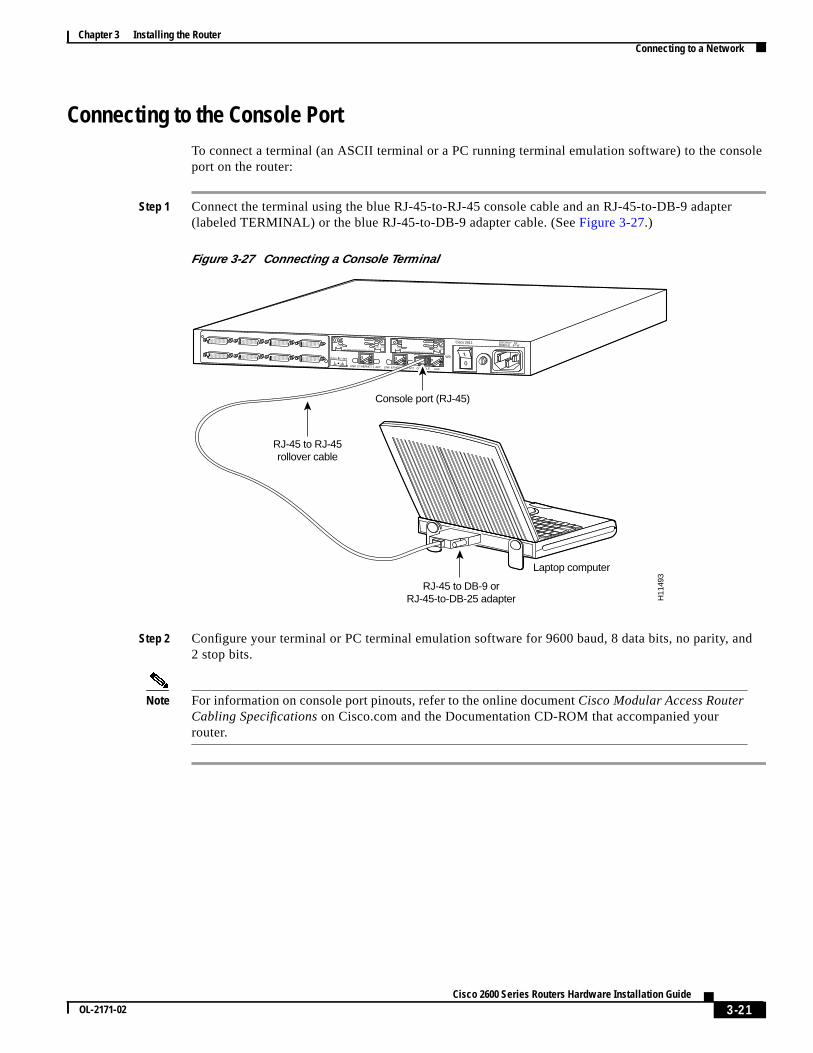
Connecting to the Console PortTo connect a terminal (an ASCII terminal or a PC running terminal emulation software) to the coport on the router:
Step 1 Connect the terminal using the blue RJ-45-to-RJ-45 console cable and an RJ-45-to-DB-9 adapte(labeled TERMINAL) or the blue RJ-45-to-DB-9 adapter cable. (SeeFigure 3-27.)
Figure 3-27 Connecting a Console Terminal
Step 2 Configure your terminal or PC terminal emulation software for 9600 baud, 8 data bits, no parity, a2 stop bits.
Note For information on console port pinouts, refer to the online documentCisco Modular Access RouterCabling Specifications on Cisco.com and the Documentation CD-ROM that accompanied yourrouter.
SEE MANUAL BEFORE INSTALLATION
SERIAL 1
SERIAL 0CONN
CONNWIC2A/SSEE MANUAL BEFORE INSTALLATION
SERIAL 1
SERIAL 0CONN
CONNWIC2A/S
Cisco 2611 100-240V– 1A50/60 Hz 47 W
W0
AUXCONSOLEETHERNET 0 ACTLINKACTETHERNET 1LINK
RJ-45 to RJ-45rollover cable
RJ-45 to DB-9 orRJ-45-to-DB-25 adapter
Console port (RJ-45)
Laptop computer
H11
493
3-21Cisco 2600 Series Routers Hardware Installation Guide
OL-2171-02

Chapter 3 Installing the RouterWhat to Do After Installing Router Hardware
issiona
ower
anied
Connecting a Modem to the Auxiliary Port
To connect a modem to the auxiliary port on the router:
Step 1 Connect a modem to the auxiliary port using the black RJ-45-to-RJ-45 auxiliary cable and theRJ-45-to-DB-25 adapter (labeled MODEM) or the black RJ-45-to-DB-25 adapter cable. (SeeFigure 3-28.)
Figure 3-28 Connecting a Modem
Step 2 Make sure that your modem and the auxiliary port on the router are configured for the same transmspeed (38400 baud is typical) and hardware flow control with Data Carrier Detect (DCD) and DatTerminal Ready (DTR) operations.
Note For information on auxiliary port pinouts, refer to the online documentCisco Modular Access RouterCabling Specifications on the Documentation CD-ROM that accompanied your router package andon Cisco.com.
What to Do After Installing Router HardwareAfter you have installed the router, connect the power cable to the rear panel of the router and the psource, and then power it ON. (If the router does not power on, proceed toAppendix A,“Troubleshooting the Router.”)
For initial configuration information, use theSoftware Configuration Guide(for Cisco 3600 series andCisco 2600 series routers) available on Cisco.com and the documentation CD-ROM that accompyour router.
SEE MANUAL BEFORE INSTALLATION
SERIAL 1
SERIAL 0CONN
CONNWIC2A/SSEE MANUAL BEFORE INSTALLATION
SERIAL 1
SERIAL 0CONN
CONNWIC2A/S
Cisco 2611 100-240V– 1A50/60 Hz 47 W
W0
AUXCONSOLEETHERNET 0 ACTLINKACTETHERNET 1LINK
Modem cable
AUX port (RJ-45)
Modem
H11
492
RJ-45 to DB-25 adapterEIA/TIA-232
3-22Cisco 2600 Series Routers Hardware Installation Guide
OL-2171-02