Installing the Hughes BGAN Remote Antenna - Ground … · Installing the Hughes BGAN Remote Antenna...
10
-
Upload
trinhnguyet -
Category
Documents
-
view
223 -
download
0
Transcript of Installing the Hughes BGAN Remote Antenna - Ground … · Installing the Hughes BGAN Remote Antenna...


HUGHES is a registered trademark of Hughes Network Systems, LLC. Hughes Network Systems, LLC All other trademarks are the property of their respective owners. 11717 Exploration Lane Germantown, MD 20876 USA © 2010 Hughes Network Systems, LLC. All rights reserved. All information is subject to change. bgan.hughes.com
Installing the Hughes BGAN Remote Antenna
Product description – BGAN Remote Antenna The Hughes BGAN Remote Antenna (HNS Part No. 9501286-0001) is designed to be permanently installed with the Basic Fixed Mount Kit (HNS part number 3004066-0002). Important Notes:
• The Hughes BGAN Remote Antenna and its cable assembly are designed for a one-time permanent installation. If the Remote Antenna is decommissioned, then the RF cable must be replaced with a new cable before the antenna is reinstalled at the same or a different location.
• The cable assembly supplied (10.0m), forms an integral part of the antenna system and is made to a specific length in order to meet the system specifications. The cable must not be cut to a shorter length, nor must cables be added to the cable run.
• It is essential that only the supplied cable is used. Third party cables may not be used; their use will invalidate the warranty of the antenna and may cause system malfunction.
The BGAN Remote Antenna kit primarily consists of the antenna and cable for connection to the BGAN satellite modem terminal. All necessary fixings are included.
Installation Instructions Step 1: Inspecting the parts Make sure you have all parts listed on the shipment box before beginning the installation; you should have the following parts:
1. Flat panel antenna 2. 10m coaxial cable terminating in N(M) and SMA(M) connectors 3. Strain relief adapter 4. Cable retaining clips 5. ¼” UNC nuts 6. Self-amalgamating tape 7. Zip strap
Step 2: Determining where to install the terminal In order for your terminal to work correctly, it must be installed in a location that provides a clear, unobstructed, line of sight between the terminal and the satellite. Any objects such as building structures or trees may degrade the quality of the satellite to terminal connection. To determine where to install the BGAN remote antenna, you need to determine that you have both a clear unobstructed line of sight to the satellite and that your fixed mount is aimed in the approximate direction to the satellite. To determine the direction from your location to the satellite follow the steps below:
1. Unpack the Hughes 9201 BGAN Satellite Modem and connect it to a Personal Computer or Mac that has the LaunchPad MMI Software installed. Follow the instructions in the Hughes 9201 user guide.
2. Power up the Hughes 9201 and launch the LaunchPad Software. 3. After LaunchPad connected successfully to the Hughes 9201 it shows the coverage map of the BGAN
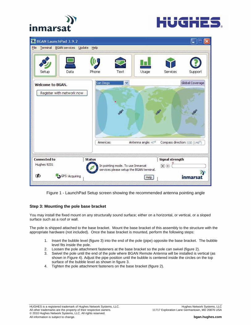
system. Click on the map to identify your approximate position. Figure 1 shows an example. 4. LaunchPad now indicates elevation angle and compass direction of the available BGAN satellite(s) for
your location. 5. Use the antenna pointing mode of the Hughes 9201 to verify that you can obtain the BGAN satellite
signal from the location where the Remote Antenna is to be installed.
HUGHES is a registered trademark of Hughes Network Systems, LLC. Hughes Network Systems, LLC All other trademarks are the property of their respective owners. 11717 Exploration Lane Germantown, MD 20876 USA © 2010 Hughes Network Systems, LLC. All rights reserved. All information is subject to change. bgan.hughes.com
Figure 1 - LaunchPad Setup screen showing the recommended antenna pointing angle Step 3: Mounting the pole base bracket You may install the fixed mount on any structurally sound surface; either on a horizontal, or vertical, or a sloped surface such as a roof or wall. The pole is shipped attached to the base bracket. Mount the base bracket of this assembly to the structure with the appropriate hardware (not included). Once the base bracket is mounted, perform the following steps:
1. Insert the bubble level (figure 3) into the end of the pole (pipe) opposite the base bracket. The bubble level fits inside the pole.
2. Loosen the pole attachment fasteners at the base bracket so the pole can swivel (figure 2). 3. Swivel the pole until the end of the pole where BGAN Remote Antenna will be installed is vertical (as
shown in Figure 4). Adjust the pipe position until the bubble is centered inside the circles on the top surface of the bubble level as shown in figure 3.
4. Tighten the pole attachment fasteners on the base bracket (figure 2).

HUGHES is a registered trademark of Hughes Network Systems, LLC. Hughes Network Systems, LLC All other trademarks are the property of their respective owners. 11717 Exploration Lane Germantown, MD 20876 USA © 2010 Hughes Network Systems, LLC. All rights reserved. All information is subject to change. bgan.hughes.com
Step 4: Mounting the terminal bracket Mount the terminal bracket to the back of the antenna using the fasteners and spanner provided (figure 5).
Figure 2 - Base bracket Figure 3 - Bubble level
Figure 4 – Pole assembly
Figure 5 – Terminal Bracket

HUGHES is a registered trademark of Hughes Network Systems, LLC. Hughes Network Systems, LLC All other trademarks are the property of their respective owners. 11717 Exploration Lane Germantown, MD 20876 USA © 2010 Hughes Network Systems, LLC. All rights reserved. All information is subject to change. bgan.hughes.com
Step 5: Mounting the terminal bracket onto the pole
1. Slide the pole collar of the terminal bracket over the end of the pole (figure 6). 2. Leave the pole collar bolts loose to allow for azimuth adjustment during pointing.
Step 6: Attaching Antenna feed cable to Antenna Important Notes:
• The cable assembly supplied (10.0m), forms an integral part of the antenna system and is made to a specific length in order to meet the system specifications. The cable must not be cut to a shorter length, nor must cables be added to the cable run.
• It is essential that only the supplied cable is used. Third party cables may not be used; their use will invalidate the warranty of the antenna and may cause system malfunction.
• It is important not to stress the connection to the antenna during installation of the coaxial antenna cable. • The minimum bend radius of the cable is 2” (50mm) however it is recommended that 4” (100mm) is not
exceeded.
1. Attach the cable to the mounting pole via a zip strap to take the weight of the cable. 2. Mate the connector to the antenna firmly by hand but do not over tighten. 3. Weatherproof the connection using the self-amalgamating tape provided (figure 7). 4. Route the cable to the BGAN satellite modem terminal avoiding any sharp bends, extremes in
temperature, and compression of the cable.
Figure 6 – Pole collar
Figure 7 – Weatherproofed Connector
HUGHES is a registered trademark of Hughes Network Systems, LLC. Hughes Network Systems, LLC All other trademarks are the property of their respective owners. 11717 Exploration Lane Germantown, MD 20876 USA © 2010 Hughes Network Systems, LLC. All rights reserved. All information is subject to change. bgan.hughes.com
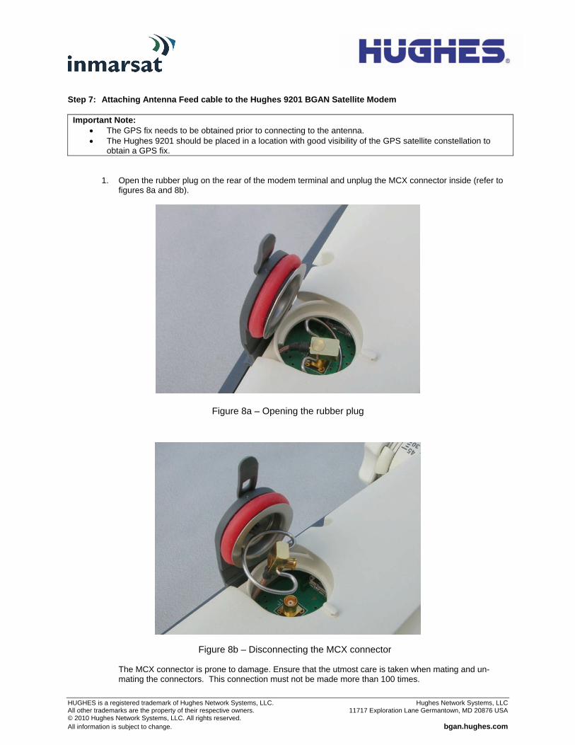
Step 7: Attaching Antenna Feed cable to the Hughes 9201 BGAN Satellite Modem
Important Note: • The GPS fix needs to be obtained prior to connecting to the antenna. • The Hughes 9201 should be placed in a location with good visibility of the GPS satellite constellation to
obtain a GPS fix.
1. Open the rubber plug on the rear of the modem terminal and unplug the MCX connector inside (refer to figures 8a and 8b).
The MCX connector is prone to damage. Ensure that the utmost care is taken when mating and un-mating the connectors. This connection must not be made more than 100 times.
Figure 8a – Opening the rubber plug
Figure 8b – Disconnecting the MCX connector
HUGHES is a registered trademark of Hughes Network Systems, LLC. Hughes Network Systems, LLC All other trademarks are the property of their respective owners. 11717 Exploration Lane Germantown, MD 20876 USA © 2010 Hughes Network Systems, LLC. All rights reserved. All information is subject to change. bgan.hughes.com
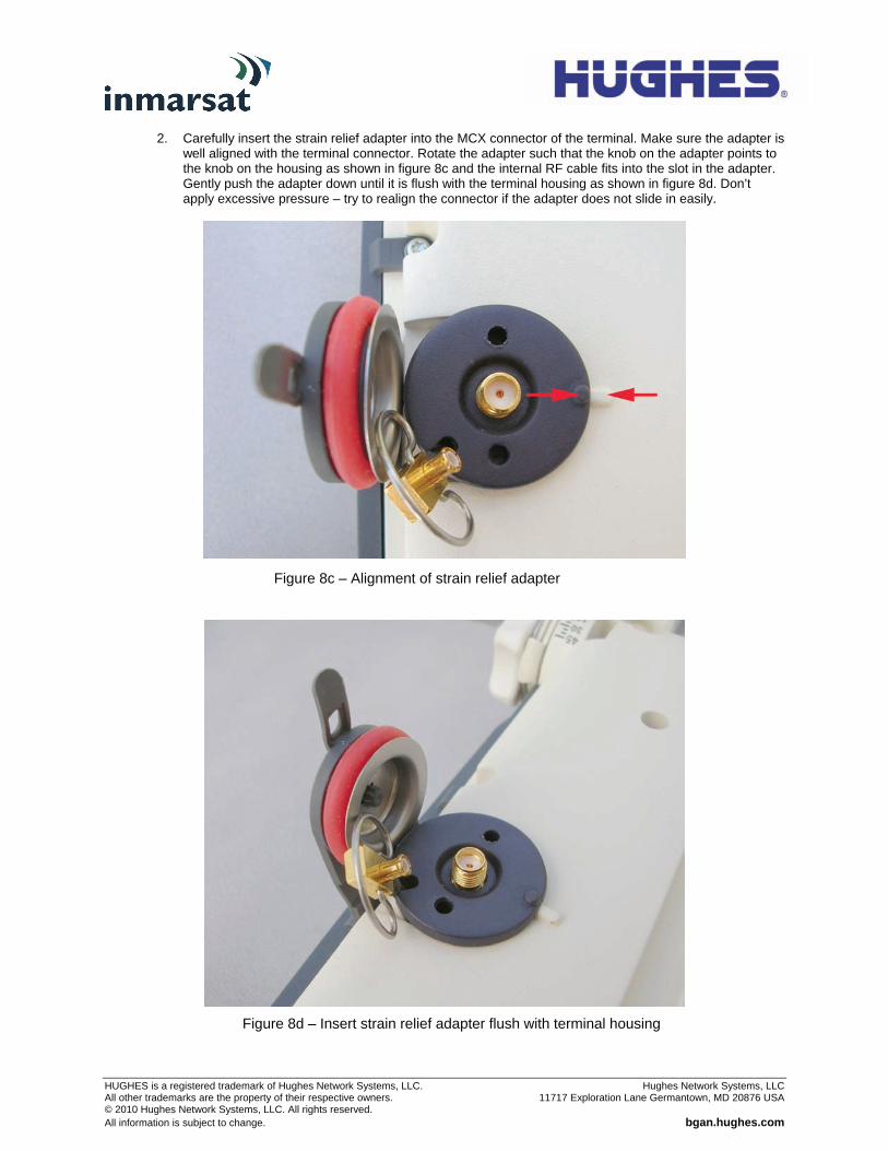
2. Carefully insert the strain relief adapter into the MCX connector of the terminal. Make sure the adapter is well aligned with the terminal connector. Rotate the adapter such that the knob on the adapter points to the knob on the housing as shown in figure 8c and the internal RF cable fits into the slot in the adapter. Gently push the adapter down until it is flush with the terminal housing as shown in figure 8d. Don’t apply excessive pressure – try to realign the connector if the adapter does not slide in easily.
Figure 8c – Alignment of strain relief adapter
Figure 8d – Insert strain relief adapter flush with terminal housing

HUGHES is a registered trademark of Hughes Network Systems, LLC. Hughes Network Systems, LLC All other trademarks are the property of their respective owners. 11717 Exploration Lane Germantown, MD 20876 USA © 2010 Hughes Network Systems, LLC. All rights reserved. All information is subject to change. bgan.hughes.com
3. Attach the antenna feed cable to the rear of the modem terminal using the provided cable clamps in the position detailed in figure 9a. Note there are two different size cable clamps to fit the varying thickness in cable.
4. Carefully plug the SMA connector into the strain relief adapter as shown in figure 9b. Tighten the connection by hand. Excessive force applied using a tool, could turn the adapter and damage the internal antenna cable.
Figure 9b – Insert SMA plug into adapter
Figure 9a – Attach antenna feed cable

HUGHES is a registered trademark of Hughes Network Systems, LLC. Hughes Network Systems, LLC All other trademarks are the property of their respective owners. 11717 Exploration Lane Germantown, MD 20876 USA © 2010 Hughes Network Systems, LLC. All rights reserved. All information is subject to change. bgan.hughes.com
Step 8: Connecting the Hughes 9201 BGAN Terminal
Refer to the Hughes 9201 Terminal User Guide for instructions to connect a Personal Computer or Mac to the terminal. Step 9: Pointing the BGAN Remote Antenna. For optimum performance, the remote antenna must be accurately pointed at the satellite. The instructions in this section explain how to mechanically adjust the antennas’ elevation and azimuth angles. These adjustments are required for pointing.
Important Notes: • To aid pointing the antenna, refer to the Hughes 9201 Terminal User Guide on how to put the terminal in
antenna pointing mode. • The terminal must be powered ON for pointing. • The GPS fix needs to be obtained prior to connecting to the antenna as explained in step 7. • The BGAN Terminal needs to be left registered on the network otherwise a new GPS fix may be required. • The Hughes 9201 may need to acquire a new GPS fix if it has been switched off for more than 42 days. In
this case it must be disconnected from the external antenna and placed in a location with good visibility of the GPS satellite constellation to obtain a GPS fix. Note: Hughes 9201 software version 3.8.0.3 and newer incorporates a Loss of Acquisition (LOA) timer that allows the 42 day time limit to be extended indefinitely as long as you register with the network at least once within the rolling 42 day period.
To adjust elevation, refer to Figure 10:
1. Loosen the two bolts in the curved slots on the terminal bracket. 2. Read the elevation angle from the elevation scale on the terminal bracket, using the red edge on the
pole collar as the angle indicator. View this edge through the curved slot on the terminal bracket. 3. Pivot the antenna to obtain the desired elevation.
To adjust azimuth, refer to Figure 11:
4. Loosen the two bolts on the pole collar. 5. Move the terminal to either side, in small increments, as necessary.
When you have maximized the signal quality, as instructed in the User Guide:
6. Tighten the two bolts in the curved slots on the terminal bracket to lock down the elevation adjustment. 7. Be careful not to change the terminal’s orientation while tightening the bolts. 8. Tighten the two bolts on the pole collar to lock down the azimuth adjustment. 9. Make sure all other fasteners on both brackets are tight.
Figure 10 – Adjusting elevation Figure 11 – Adjusting azimuth

HUGHES is a registered trademark of Hughes Network Systems, LLC. Hughes Network Systems, LLC All other trademarks are the property of their respective owners. 11717 Exploration Lane Germantown, MD 20876 USA © 2010 Hughes Network Systems, LLC. All rights reserved. All information is subject to change. bgan.hughes.com
Lightning Protection and Safety A lightning strike on the antenna, mounting hardware or cable may cause death or serious injury and is likely to damage both the antenna and the BGAN Terminal. It is therefore essential that the installer does not employ an installation location, which is likely to experience a lightning strike, and make suitable grounding and lightning protection arrangements to minimize any possibility of injury or damage. Professional local advice should be sought with respect to these matters. Hughes accepts no liability for any injury or damage caused by lightning strikes.
Disclaimer Whilst prepared in good faith, Hughes makes no warranty or representation as to the accuracy, completeness or fitness for purpose of this document or its contents and all warranties, whether express or implied are excluded. Hughes, to the maximum extent permitted by law, excludes any liability arising from the use of this document or its contents. Users’ attention is brought to the fact that the local applicable laws and regulations as to the use of the remote antenna may apply and it is the user’s responsibility to identify and comply with these.