Installing and Upgrading Internal Modules - cisco.com · cover, as described in the “Removing the...
8
B-1 Cisco IAD2801 Series Integrated Access Devices Hardware Installation Guide OL-12433-01 APPENDIX B Installing and Upgrading Internal Modules This document describes how to install or upgrade modules that are located internally within your Cisco IAD2801 series integrated access devices, such as memory modules, packet voice data modules (PVDMs), and power supplies. You need to remove the cover from the router to install or remove any of these items. The document contains the following sections: • Safety Warnings, page B-1 • Removing the Chassis Cover, page B-2 • Locating Modules, page B-4 • Replacing the Power Supply, page B-5 • Installing the Chassis Cover, page B-6 Before you perform any of these module replacement procedures, disconnect the power and remove the cover, as described in the “Removing the Chassis Cover” section on page B-2. After you complete the module replacement procedures, install the chassis cover as described in the “Installing the Chassis Cover” section on page B-6. Safety Warnings Warning This equipment must be grounded. Never defeat the ground conductor or operate the equipment in the absence of a suitably installed ground conductor. Contact the appropriate electrical inspection authority or an electrician if you are uncertain that suitable grounding is available. Statement 1024 Warning Only trained and qualified personnel should be allowed to install, replace, or service this equipment. Statement 1030 Warning Before working on a system that has an on/off switch, turn OFF the power and unplug the power cord. Statement 1 Warning Read the installation instructions before connecting the system to the power source. Statement 1004
Transcript of Installing and Upgrading Internal Modules - cisco.com · cover, as described in the “Removing the...

Cisco IAD2801 Series Integrated AOL-12433-01
A
P P E N D I X B Installing and Upgrading Internal ModulesThis document describes how to install or upgrade modules that are located internally within your Cisco IAD2801 series integrated access devices, such as memory modules, packet voice data modules (PVDMs), and power supplies. You need to remove the cover from the router to install or remove any of these items. The document contains the following sections:
• Safety Warnings, page B-1
• Removing the Chassis Cover, page B-2
• Locating Modules, page B-4
• Replacing the Power Supply, page B-5
• Installing the Chassis Cover, page B-6
Before you perform any of these module replacement procedures, disconnect the power and remove the cover, as described in the “Removing the Chassis Cover” section on page B-2. After you complete the module replacement procedures, install the chassis cover as described in the “Installing the Chassis Cover” section on page B-6.
Safety Warnings
Warning This equipment must be grounded. Never defeat the ground conductor or operate the equipment in the absence of a suitably installed ground conductor. Contact the appropriate electrical inspection authority or an electrician if you are uncertain that suitable grounding is available. Statement 1024
Warning Only trained and qualified personnel should be allowed to install, replace, or service this equipment. Statement 1030
Warning Before working on a system that has an on/off switch, turn OFF the power and unplug the power cord. Statement 1
Warning Read the installation instructions before connecting the system to the power source. Statement 1004
B-1ccess Devices Hardware Installation Guide
Appendix B Installing and Upgrading Internal Modules Removing the Chassis Cover
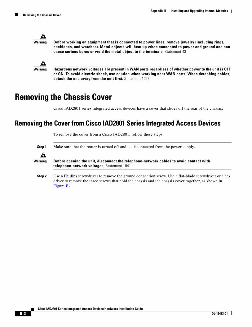
Warning Before working on equipment that is connected to power lines, remove jewelry (including rings, necklaces, and watches). Metal objects will heat up when connected to power and ground and can cause serious burns or weld the metal object to the terminals. Statement 43
Warning Hazardous network voltages are present in WAN ports regardless of whether power to the unit is OFF or ON. To avoid electric shock, use caution when working near WAN ports. When detaching cables, detach the end away from the unit first. Statement 1026
Removing the Chassis CoverCisco IAD2801 series integrated access devices have a cover that slides off the rear of the chassis.
Removing the Cover from Cisco IAD2801 Series Integrated Access DevicesTo remove the cover from a Cisco IAD2801, follow these steps:
Step 1 Make sure that the router is turned off and is disconnected from the power supply.
Warning Before opening the unit, disconnect the telephone-network cables to avoid contact with telephone-network voltages. Statement 1041
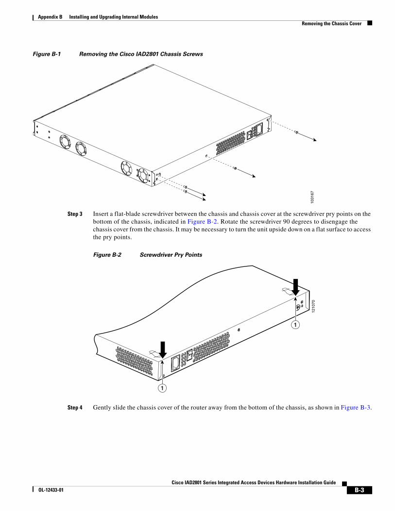
Step 2 Use a Phillips screwdriver to remove the ground connection screw. Use a flat-blade screwdriver or a hex driver to remove the three screws that hold the chassis and the chassis cover together, as shown in Figure B-1.
B-2Cisco IAD2801 Series Integrated Access Devices Hardware Installation Guide
OL-12433-01
Appendix B Installing and Upgrading Internal Modules Removing the Chassis Cover
Figure B-1 Removing the Cisco IAD2801 Chassis Screws
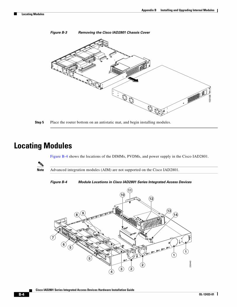
Step 3 Insert a flat-blade screwdriver between the chassis and chassis cover at the screwdriver pry points on the bottom of the chassis, indicated in Figure B-2. Rotate the screwdriver 90 degrees to disengage the chassis cover from the chassis. It may be necessary to turn the unit upside down on a flat surface to access the pry points.
Figure B-2 Screwdriver Pry Points
Step 4 Gently slide the chassis cover of the router away from the bottom of the chassis, as shown in Figure B-3.
1031
6712
1070
1
1
B-3Cisco IAD2801 Series Integrated Access Devices Hardware Installation Guide
OL-12433-01
Appendix B Installing and Upgrading Internal Modules Locating Modules
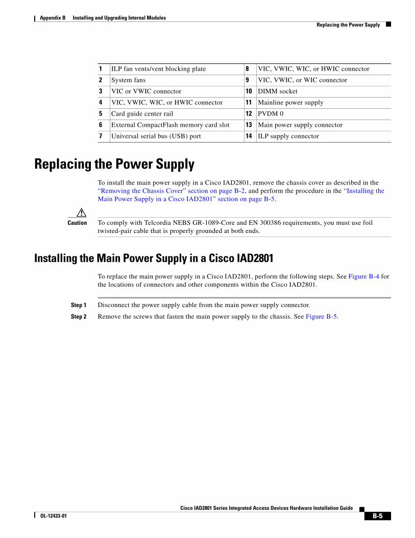
Figure B-3 Removing the Cisco IAD2801 Chassis Cover
Step 5 Place the router bottom on an antistatic mat, and begin installing modules.
Locating ModulesFigure B-4 shows the locations of the DIMMs, PVDMs, and power supply in the Cisco IAD2801.
Note Advanced integration modules (AIM) are not supported on the Cisco IAD2801.
Figure B-4 Module Locations in Cisco IAD2801 Series Integrated Access Devices
1031
68
2304
40
1011
12
22
11
34
5
56
7
8 9 1413
B-4Cisco IAD2801 Series Integrated Access Devices Hardware Installation Guide
OL-12433-01
Appendix B Installing and Upgrading Internal Modules Replacing the Power Supply
Replacing the Power SupplyTo install the main power supply in a Cisco IAD2801, remove the chassis cover as described in the “Removing the Chassis Cover” section on page B-2, and perform the procedure in the “Installing the Main Power Supply in a Cisco IAD2801” section on page B-5.
Caution To comply with Telcordia NEBS GR-1089-Core and EN 300386 requirements, you must use foil twisted-pair cable that is properly grounded at both ends.
Installing the Main Power Supply in a Cisco IAD2801To replace the main power supply in a Cisco IAD2801, perform the following steps. See Figure B-4 for the locations of connectors and other components within the Cisco IAD2801.
Step 1 Disconnect the power supply cable from the main power supply connector.
Step 2 Remove the screws that fasten the main power supply to the chassis. See Figure B-5.
1 ILP fan vents/vent blocking plate 8 VIC, VWIC, WIC, or HWIC connector
2 System fans 9 VIC, VWIC, or WIC connector
3 VIC or VWIC connector 10 DIMM socket
4 VIC, VWIC, WIC, or HWIC connector 11 Mainline power supply
5 Card guide center rail 12 PVDM 0
6 External CompactFlash memory card slot 13 Main power supply connector
7 Universal serial bus (USB) port 14 ILP supply connector
B-5Cisco IAD2801 Series Integrated Access Devices Hardware Installation Guide
OL-12433-01

Appendix B Installing and Upgrading Internal Modules Installing the Chassis Cover
Figure B-5 Cisco IAD2801 Main Power Supply Removal.
Step 3 Lift the main power supply out of the chassis.
Step 4 Install the new power supply.
Step 5 Connect the main power supply cable to the main power supply connector.
Installing the Chassis CoverCisco IAD2801 series integrated access devices have a cover that slides onto the chassis from the rear of the chassis. For cover installation procedures, see the “Installing the Cover on Cisco IAD2801 Series Integrated Access Devices” section on page B-7.
1 Main power supply fastening screws 4 Main power connector
2 Vent blocking plate fastening screws 5 Main power supply
3 Vent blocking plate
1
2
1030
59
3
4
5
B-6Cisco IAD2801 Series Integrated Access Devices Hardware Installation Guide
OL-12433-01

Appendix B Installing and Upgrading Internal Modules Installing the Chassis Cover
Installing the Cover on Cisco IAD2801 Series Integrated Access DevicesTo install the chassis cover on a Cisco IAD2801, follow these steps:
Step 1 Slide the top cover of the router back on the bottom of the chassis by pushing it in the direction opposite than shown in Figure B-3 on page B-4, “Removing the Cisco IAD2801 Chassis Cover.”
Step 2 Replace the three screws and the ground connection that you removed when you opened the chassis. See Figure B-1 on page B-3, “Removing the Cisco IAD2801 Chassis Cover.”
B-7Cisco IAD2801 Series Integrated Access Devices Hardware Installation Guide
OL-12433-01
Appendix B Installing and Upgrading Internal Modules Installing the Chassis Cover
B-8Cisco IAD2801 Series Integrated Access Devices Hardware Installation Guide
OL-12433-01