INSTALLER’S MANUAL PAGER TVM 800 - Ampirepdf.ampire.de/TVM800_english.pdf · The questionnaire...
17
INSTALLER’S MANUAL PAGER TVM 800 WARNING - Please follow the instructions in this manual thoroughly. - The personnel in charge of installation are not authorised to remove the guarantee seals and/or access the interior of the product and theaccessories. - The personnel in charge of installation are not authorised to make any modifications and/or adaptations to the product and the relative accessories. - The manufacturer is not liable for any damage or injury caused by incorrect installation of the product and the relative accessories. TECHNICAL SPECIFICATIONS Dimensions:...............................................................................................160x90x30 , 270g Power supply:...............................................................................................................12VDC Operating temperature:..............................................................................................-25º +70ºC Consumption*:...............................................................................................................<5mA *When the peripheral unit is armed, the GPS is off, the keypad is off, the Sat Programmer is disconnected and the internal back-up battery is fully charged. DISCONNECT THE CAR BATTERY 1 EN PRESS TO RELEASE Release and position the lever as shown in the figure before connecting the 18-pin loose connector to the terminal. CONNECTOR CONNECTIONS Lock the connector to the terminal by positioning the lever as shown in the figure. CONNECTIONS Connect the connectors to the terminal PHASE 2 PHASE 3 PHASE Fig.2 Fig.3 Fig.4 WARNING: make sure that the connector is inserted and locked to the terminal in the correct way. Fig.1 * : SUGGESTED 1 5A SAT PROGRAMMER * 2 3 DARK BLUE MAROON OUT 3 OUT 2 OUT 1 CAR ALARM BUZZ AL 4 3 2 DO NOT USE DO NOT USE DO NOT USE DO NOT USE DO NOT USE Insert SIM GSM ANTENNA GPS ANTENNA EARTH POSITIVE BATTERY TERMINAL (+12V) PLUS IGNITION KEY (+15) DO NOT USE START ENGINE CUT OFF
Transcript of INSTALLER’S MANUAL PAGER TVM 800 - Ampirepdf.ampire.de/TVM800_english.pdf · The questionnaire...

INSTALLER’S MANUALPAGER TVM 800
WARNING- Please follow the instructions in this manual thoroughly.- The personnel in charge of installation are not authorised to remove the guarantee seals and/or access the interior of the product and theaccessories.- The personnel in charge of installation are not authorised to make any modifications and/or adaptations to the product and the relative accessories.- The manufacturer is not liable for any damage or injury caused by incorrect installation of the product and the relative accessories.
TECHNICAL SPECIFICATIONSDimensions:...............................................................................................160x90x30 , 270gPower supply:...............................................................................................................12VDCOperating temperature:..............................................................................................-25º +70ºCConsumption*:...............................................................................................................<5mA*When the peripheral unit is armed, the GPS is off, the keypad is off, the Sat Programmer is disconnected and the internal back-up battery is fully charged.
DISCONNECT THE CAR BATTERY
1
EN
PRESS TORELEASE
Release and position the leveras shown in the figure beforeconnecting the 18-pin looseconnector to the terminal.
CONNECTORCONNECTIONS
Lock the connector to the terminal by positioning the leveras shown in the figure.
CONNECTIONS
Connect the connectorsto the terminal
PHASE
2PHASE
3PHASE
Fig.2
Fig.3 Fig.4
WARNING: make sure that the connector is insertedand locked to the terminal in the correct way.
Fig.1* : SUGGESTED
1
5A
SATPROGRAMMER
*
2
3
DARK BLUE
MAROON
OUT 3
OUT 2
OUT 1
CAR ALARM
BUZZ
AL
4
3
2
DO NOT USE
DO NOT USE
DO NOT USE
DO NOT USE
DO NOT USE
InsertSIM
GSMANTENNA
GPSANTENNA
EARTH
POSITIVEBATTERY
TERMINAL (+12V)
PLUS IGNITIONKEY (+15)
DO NOT USE
STARTENGINECUT OFF
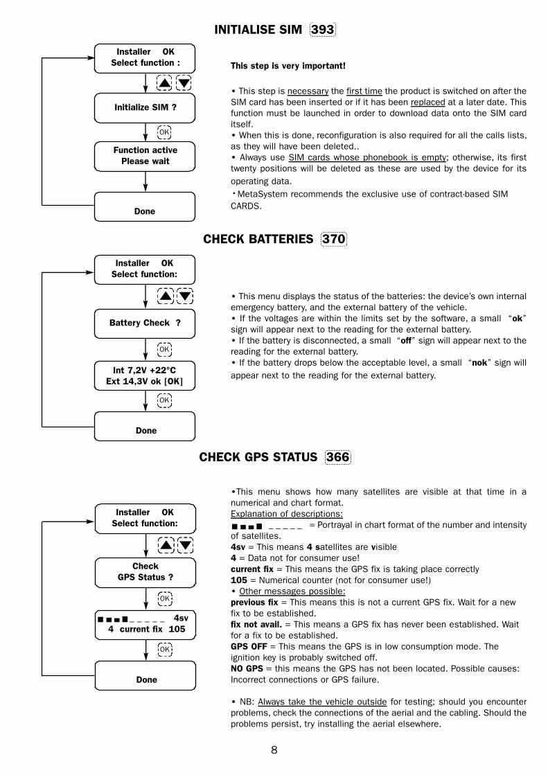
• Place the device in a concealed position inside the vehicle’s seating area.• It is essential that the location of the device can be reached easily with the sat programmer.• Do not place it underneath carpet mats, areas subject to tread or loading areas.• It is reccomended to fix the unit to a rigid part of the vehicle chassis and complete taping the wiring.
POSITION OF THE DEVICE
GSMANTENNA
AFTER DECIDING WHERE TO INSTALL THE ANTENNA, CHECK ITS RECEPTION BEFORE SECURING IT:- CONNECT THE SAT PROGRAMMER AND CHECK OPERATION USING THE DEDICATED FUNCTION (SEE RELATIVE MANUAL).
OK OK OK
OK
IT MUST NOT BEVISIBLE OR EASY TOREACH FROM THE
OUTSIDE
DO NOT COVER WITHPARTS IN METAL OR
METALLIC PARTS
CLEAN THESURFACE
WITH CARE
THE ANTENNA ISRESINPOTTED AND CAN ALSO
BEPLACED OUTSIDETHEVEHICLE (E.G. BEHINDTHE
BUMPER, INSIDEAHEADLAMP...)
THE ANTENNA ISRESINPOTTED AND CAN
ALSO BEPLACEDOUTSIDE THEVEHICLE
(E.G. BEHINDTHEBUMPER, INSIDEA
HEADLAMP...)
90°
NOOK
OK OK OK
OK
IT MUST NOT BEVISIBLE OR EASY TOREACH FROM THE
OUTSIDE
DO NOT COVER WITHPARTS IN METAL OR
METALLIC PARTS
KOOK
AFTER DECIDING WHERE TO INSTALL THE ANTENNA,CHECK ITSRECEPTION BEFORE SECURING IT:- PARK THE VEHICLE IN AN OPEN SPACE FAR FROM TALL BUILDINGS- CONNECT THE SAT PROGRAMMER AND CHECK OPERATION USING THE DEDICATED FUNCTION (SEE RELATIVE MANUAL).
GPSANTENNA
CONNECTION OF GSM ANTENNA
CONNECTION OF GPS ANTENNA
• THE ANTENNA CAN BE FIXED DIRECTLY ON A METALLIC SURFACE (MAGNETIC BASE)• FOR NON-METALLIC SURFACE USE THE ADHESIVE TAPE SUPPLIED.
CLEAN THESURFACE
WITH CARE
Fig.5
Fig.6
Fig.7
INPUT FOR EXTERNAL VOL 1 ALARM
Fig.9
AUXILIARYALARMOUTPUT
CONNECT THE SAT PROGRAMMER(SEE SAT PROGRAMMER MANUAL)AND SEE THE TYPE OF CONTROL
(POSITIVE OR NEGATIVE).
CONNECTION OF IGNITION IMMOBILISATION (25A)
Fig.8
87 30
86 85
(50)
OUT 2
IGNITIONKEY BLOCK
CUT ORIGINAL WIRE
STARTERMOTOR
AL

INSTALLATION
AND
PROGRAMMING
INSTRUCTION MANUAL
Pager
TVM 800
V817390A
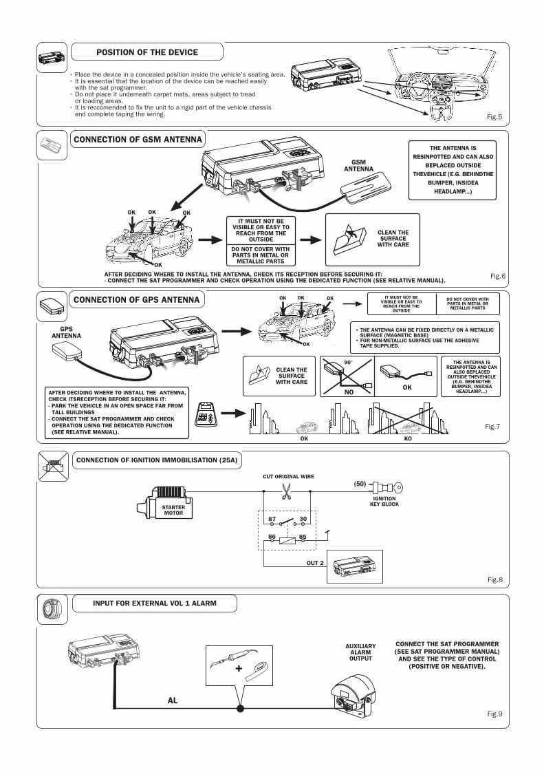
This manual describes the steps that should be followed in order to install this product correctly.
This procedure has been designed in order to guarantee a rapid and reliable installation; therefore, we strongly recommend
you follow these instructions carefully.
WARNING
- Please follow the instructions in this manual thoroughly
· Personnel in charge of installation are not authorised to remove the guarantee seals and/or access the interior of the
product and the accessories
· Personnel in charge of installation are not authorised to make any modifications and/or adaptations to the product and
the relative accessories
The manufacturer is not liable for any damage or injury caused by the incorrect installation of the product and the
relative accessories
Important:
The product enables SMS communication using GSM technology.Therefore, a SIM card is required, for it to function properly
(not supplied by MetaSystem). MetaSystem recommends the exclusive use of contract-based SIM cards to ensure optimum
operation of the product
INDEX
QUESTIONNAIRE FOR THE VEHICLE’S OWNER 3
CONFIGURATION PROCEDURE 5
CHECKING AND CONFIGURATION FOR INSTALLATION 5
CUSTOMIZATION 5
THE SAT PROGRAMMER 6
HOW TO ACCESS MENUS (ACCESS LEVELS) 6
PROGRAMMING MENUS 7
DISPLAY-ONLY MENUS 12
HIDDEN MENUS CALLED UP BY QUICK COMMANDS 13
VEHICLE CONSIGNMENT 14
CUSTOMIZING THE PASSWORDS 14
SWITCHING THE DEVICE ON AND OFF 15
2

QUESTIONNAIRE FOR THE VEHICLE’S OWNER
The questionnaire below should be filled in to ensure that the configuration of the device complies with the owner’s
preferences.
What is the SIM number and its release PIN number?
(should only be requested if supplied by the owner!)
SIM : ________________________
PIN : _________
What numbers are to be added to the phonebook? (explain about the Golden Numbers!)
Pos ___ N° _____________ Pos ___ N° _____________ Pos ___ N° _____________ Golden number
Pos ___ N° _____________ Pos ___ N° _____________ Pos ___ N° _____________ Pos 81 N° _____________
Pos ___ N° _____________ Pos ___ N° _____________ Pos ___ N° _____________ Pos 82 N° _____________
Pos ___ N° _____________ Pos ___ N° _____________ Pos ___ N° _____________ Pos 83 N° _____________
Pos ___ N° _____________ Pos ___ N° _____________ Pos ___ N° _____________ Pos 84 N° _____________
Pos ___ N° _____________ Pos ___ N° _____________ Pos ___ N° _____________ Pos 85 N° _____________
Pos ___ N° _____________ Pos ___ N° _____________ Pos ___ N° _____________ Pos 86 N° _____________
Pos ___ N° _____________ Pos ___ N° _____________ Pos ___ N° _____________ Pos 87 N° _____________
Pos ___ N° _____________ Pos ___ N° _____________ Pos ___ N° _____________ Pos 88 N° _____________
Pos ___ N° _____________ Pos ___ N° _____________ Pos ___ N° _____________ Pos 89 N° _____________
Pos ___ N° _____________ Pos ___ N° _____________ Pos ___ N° _____________ Pos 90 N° _____________
Configuration of the calls lists? (phonebook position and format)
THEFT ALARM List
CH1 Pos:____For:_____
CH2 Pos:____For:_____
CH3 Pos:____For:_____
CH4 Pos:____ For:_____
CH5 Pos:____ For:_____
LOW BATTERY List
CH1 Pos:____ For:_____
CH2 Pos:____ For:_____
CH3 Pos:____ For:_____
CH4 Pos:____ For:_____
CH5 Pos:____ For:_____
SPEED WARNING List
CH1 Pos:____ For:_____
CH2 Pos:____ For:_____
CH3 Pos:____ For:_____
CH4 Pos:____ For:_____
CH5 Pos:____ For:_____
BATTERY ALARM List
CH1 Pos:____ For:_____
CH2 Pos:____ For:_____
CH3 Pos:____ For:_____
CH4 Pos:____ For:_____
CH5 Pos:____ For:_____
CAR ALARM List
CH1 Pos:____ For:_____
CH2 Pos:____ For:_____
CH3 Pos:____ For:_____
CH4 Pos:____ For:_____
CH5 Pos:____ For:_____
PERIODIC List
CH1 Pos:____ For:_____
CH2 Pos:____ For:_____
CH3 Pos:____ For:_____
CH4 Pos:____ For:_____
CH5 Pos:____ For:_____
Abbreviations used:
S = SMS
V = VOICE
S+V = SMS+VOICE
V/S = VOICE/SMS
Do you want vitality transmission?
If YES, how often do you want this to take place?
At what speed limit do you want a warning to be sent?
YES NO
Every _____________
Km/h_____________
3


- The steps described below must be followed after all the cabling on the vehicle has been completed according to the
enclosed installation manual.
- Unblock the SIM card after it has been switched on by keying in the release PIN number if necessary.
- Connect a Sat Programmer as described in the following pages.
- Enter INSTALLER level and complete the steps for configuration by following the instructions given in the descriptions of
the menus.
Important:The product enables SMS communication using GSM technology. Therefore a SIM card is required (not supplied by
MetaSystem) for it to function correctly. MetaSystem recommends the exclusive use of contract-based SIM cards to ensure
optimum operation of the product.
Complete programming according to the steps described below to safeguard correct installation
CONFIGURATION PROCEDURE
CHECKING AND CONFIGURATION FOR INSTALLATION
CUSTOMISATION
❒ Check the GSM signal (enter PIN if requested)❒ Complete the SIM initialisation procedure (this is a very important step and must be carried out before any other
programming!)
❒ Complete the battery check
❒ Check the GPS signal
❒ Complete programming of the maximum number of alarms for VOL1
❒ Complete programming of the immunity against external alarms
❒ Complete programming of the delay before starting GSM calls
❒ Check the inputs in the “Display I/O” menu; the inputs are:
❒ Ignition signal
❒ VOL1 signal (vehicle alarm)
When the above has been completed correctly, the device can be installed permanently and any parts that were taken off the
vehicle can now be replaced.
Complete any customisation of the device using the “Questionnaire for the vehicle’s owner”
❒ Complete programming of the phonebook
❒ Enter the vehicle’s number plate
❒ Complete programming of the calls lists (we recommend programming the CAR ALARM list first as configuration is
always necessary if present and connected to an external alarm).
❒ CAR ALARM (must always be set)
❒ THEFT ALARM (only if required)
❒ BATTERY ALARM (only if required)
❒ SPEED WARNING (only if required)
❒ LOW BATTERY (only if required)
❒ PERIODIC (only if required)
❒ Set vitality transmission (the default setting is ‘not active’)
❒ Set the speed limit
5

SCROLL UP
KEY TO GO THROUGH
MENU (FORWARDS)
- KEY TO ENTER MENU
- CONFIRM FUNCTIONS
- STORE DATA
DISPLAY MESSAGES
OKENTER
KEY TO DELETE AND EXIT
WITHOUT MAKING
CHANGES
CCANCEL
KEY TO ENTER DATA IN
LETTERS AND NUMBERS
1*
2ABC
3DEF
4GHI
5JKL
6MNO
7PQRS
8TUV
9WXYZ
cCANCEL
0SPACE
OKENTER
+
SWITCHING ON
• Connect the Sat programmer.
The display appears as shown opposite, indicating that
the device is in maintenance mode.
DESCRIPTION
SOLVING PROBLEMS WHEN SWITCHING ON
PROBLEM
• Does not switch on• Check electrical connections especially connectionsto the power supply
• Check connection of the SAT Programmer to the
device.Contact the Help Desk if the problem persists
THE SAT PROGRAMMERThe system must be checked by means of the dedicated ‘Sat Programmer’ interface
6
TVM800 OK
In maintenance
MESSAGE ON THE DISPLAY
HOW TO ACCESS MENUS (ACCESS LEVELS)
Access to menus is structured in levels that are entered by keying in the relative passwords.
These must be changed once the system has been installed.
All the menus needed to complete the configuration of the product are present at INSTALLER level. As you go down the
various levels, only certain utility menus will remain accessible. The structure in levels prevents the possibility of
parameters being altered by unauthorised personnel.
It is possible to scroll through all the menus available after a level has been reached using the ( s t ) arrows.
SOLUTION
MULTIFUNCTION
KEYS+
-
SCROLL DOWN
KEY TO GO THROUGH
MENU (BACKWARDS)

Activate Instal.
password ?
Installer OK
Select function:
BLOCKED level
UNBLOCKED level (User)
UNBLOCK FUNCTIONS level (Owner)
INSTALLER level
NB
The initial display may show “ACCESS DENIED…. INSERT CODE” instead of “DEACTIVATED …..(IN MAINTENANCE)”: this
appears when the module is no longer being maintained!
deactivated
(in maintenance)
TVM800 OK
In maintenance
Activate Funct.
password?
Functions active
Select function:
0
0
OK
OK
OK
OK
0 OK
11111
33333
OK44444
PROGRAMMING MENUS
From INSTALLER level, it is possible to display all the menus required for the configuration of the product.
It is possible to scroll through the various menus using the ( s t ) arrow keys.
For a more rapid display of each menu, it is possible to enter the relative quick command directly followed by OK (the
quick commands are shown in the boxes next to the menus).
Installer OK
Select function :
Check
GSM Status?
SIGNAL GSM 50%
= = = = =
CHECK GSM STATUS 365
•Warning: if the device realises that the SIM requires unblocking when the
menu is accessed, the PIN must be entered to release it. In this case,
press the + key and key in the PIN when the relevant screen appears, then
confirm by means of the OK key.
• This menu confirms the quality of the current GSM signal and is shown
both as a percentage and in a chart format.
• Other information provided:
NO GSM = this means that no GSM signal has been captured. Possible
causes: Incorrect connection of the aerial or failure of internal GSM module.GSM module in low power mode = this means that the GSM is in low
consumption mode. The ignition key is probably switched off.
GSM signal too low = the signal must be at least 20%. Take the vehicle
outside; check the connection of the GSM aerial; check the cables; change
the place where the GSM aerial is installed; the signal from the telephone
service provider may be weak.
GSM module status Undefined
GSM module not answering..
Error SIM card not found:
Should one of the above messages appear, exit the menu and enter 999;
press OK and wait …. The device will reset after a few seconds. Try again 2
or 3 times; if the problems persist, contact our Help Desk
Done
OK
OK
MODES OF ACCESS TO THE VARIOUS LEVELS
7
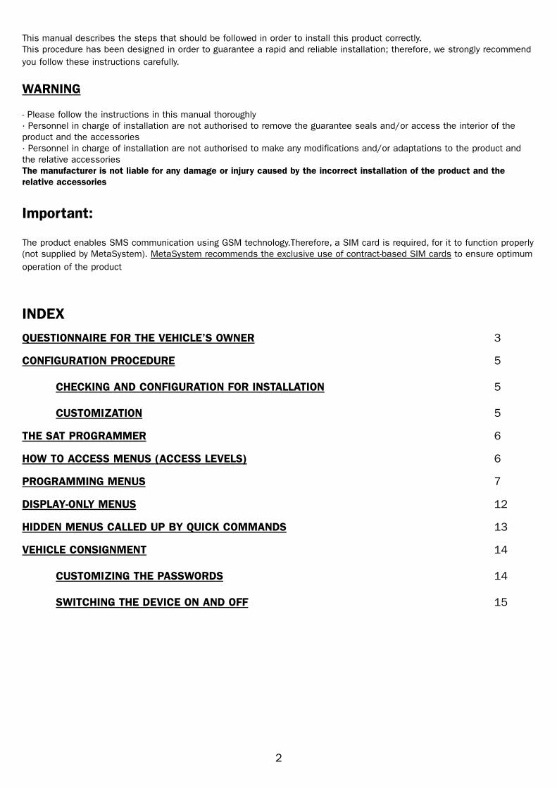
INITIALISE SIM 393
Installer OK
Select function :
Initialize SIM ?
Function active
Please wait
Done
Installer OK
Select function:
Battery Check ?
Int 7,2V +22°C
Ext 14,3V ok [OK]
Done
This step is very important!
• This step is necessary the first time the product is switched on after the
SIM card has been inserted or if it has been replaced at a later date. This
function must be launched in order to download data onto the SIM card
itself.
• When this is done, reconfiguration is also required for all the calls lists,
as they will have been deleted..
• Always use SIM cards whose phonebook is empty; otherwise, its first
twenty positions will be deleted as these are used by the device for its
operating data.
•MetaSystem recommends the exclusive use of contract-based SIM
CARDS.
• This menu displays the status of the batteries: the device’s own internal
emergency battery, and the external battery of the vehicle.
• If the voltages are within the limits set by the software, a small “ok”
sign will appear next to the reading for the external battery.
• If the battery is disconnected, a small “off” sign will appear next to the
reading for the external battery.
• If the battery drops below the acceptable level, a small “nok” sign will
appear next to the reading for the external battery.
CHECK BATTERIES 370
OK
OK
OK
Installer OK
Select function:
Check
GPS Status ?
_ _ _ _ _ 4sv
4 current fix 105
Done
OK
OK
CHECK GPS STATUS 366
•This menu shows how many satellites are visible at that time in a
numerical and chart format.
Explanation of descriptions:
_ _ _ _ _ = Portrayal in chart format of the number and intensity
of satellites.
4sv = This means 4 satellites are visible
4 = Data not for consumer use!
current fix = This means the GPS fix is taking place correctly
105 = Numerical counter (not for consumer use!)
• Other messages possible:
previous fix = This means this is not a current GPS fix. Wait for a new
fix to be established.
fix not avail. = This means a GPS fix has never been established. Wait
for a fix to be established.
GPS OFF = This means the GPS is in low consumption mode. The
ignition key is probably switched off.
NO GPS = this means the GPS has not been located. Possible causes:
Incorrect connections or GPS failure.
• NB: Always take the vehicle outside for testing; should you encounter
problems, check the connections of the aerial and the cabling. Should the
problems persist, try installing the aerial elsewhere.
8
9
Installer OK
Select function :
Max VOL1/2
alarms: 10
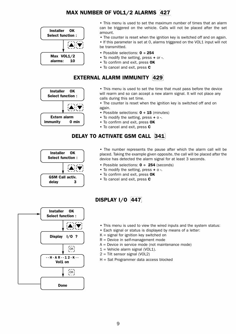
MAX NUMBER OF VOL1/2 ALARMS 427
• This menu is used to set the maximum number of times that an alarm
can be triggered on the vehicle. Calls will not be placed after the set
amount.
• The counter is reset when the ignition key is switched off and on again.
• If this parameter is set at 0, alarms triggered on the VOL1 input will not
be transmitted.
• Possible selections: 0 ÷ 254
• To modify the setting, press + or -.
• To confirm and exit, press OK
• To cancel and exit, press C
EXTERNAL ALARM IMMUNITY 429
Installer OK
Select function :
• This menu is used to set the time that must pass before the device
will rearm and so can accept a new alarm signal. It will not place any
calls during this set time.
• The counter is reset when the ignition key is switched off and on
again.
• Possible selections: 0 ÷ 15 (minutes)
• To modify the setting, press + o -.
• To confirm and exit, press OK
• To cancel and exit, press C
Extern alarm
immunity 0 min
Installer OK
Select function :
GSM Call activ.
delay 3
DELAY TO ACTIVATE GSM CALL 341
• The number represents the pause after which the alarm call will be
placed. Taking the example given opposite, the call will be placed after the
device has detected the alarm signal for at least 3 seconds.
• Possible selections: 0 ÷ 254 (seconds)
• To modify the setting, press + o -.
• To confirm and exit, press OK
• To cancel and exit, press C
Installer OK
Select function :
Display I/O ?
- - H - A R - - 1 2 - K - -
Vol1 on
Done
DISPLAY I/O 447
• This menu is used to view the wired inputs and the system status:
• Each signal or status is displayed by means of a letter:
K = signal for ignition key switched on
R = Device in self-management mode
A = Device in service mode (not maintenance mode)
1 = Vehicle alarm signal (VOL1).
2 = Tilt sensor signal (VOL2)
H = Sat Programmer data access blocked
OK
OK

PHONEBOOK 205
Installer OK
Select function :
Phonebook Edit
Index ?
Index >> - -
Index >> 81
Index : 81
>> available <<
Index : 81
+393480153683
• This menu is used to store the telephone numbers, including those
which will be called in case of alarm.
• The phonebook holds up to 90 numbers.
• These 90 numbers include ten Golden Numbers (from 81 to 90), i.e.
telephone numbers that are able to interact with the vehicle by means of
commands entered on the mobile phone. If control via mobile phone is
required, the relative telephone number must be stored in one of these
positions.
• After you have entered a position in the phonebook, the message
>> available << will appear if it is vacant.
• If the position is occupied, the number stored there will appear; you can
replace the old number by writing over it with a new number. Otherwise,
press the – key followed by OK to clear the position.
• Use the s and t keys to select the next positions in the phonebook.
• If you make a mistake when entering in numbers, simply press the – key.
• To confirm, press OK. You will hear a long beep without seeing any
change in the display.
• To cancel and exit, press C
Important: the international country code must always be entered when
keying in telephone numbers (e.g. +39 or 0039 for Italy).
C to exit OK to store
Enter phonebook
position
Enter the telephonenumber
OK
OK
C
C
Installer OK
Select function :
Vehc. Plate
(8 chs.)
Vehc. Plate
(8 chs) AM184NT
Done
VEHICLE NUMBER PLATE 307
• The number plate can be composed of maximum 8 digits.
• To enter a letter, press the relevant key on the Sat Programmer
repeatedly until it is displayed
• To confirm and go on to the next digit, press the + key; a dot “ • “ will
appear on the display next to the digit you have just entered.
• Press the - key to delete the digit you have just entered
• To confirm and exit, press OK
• To cancel and exit, press CEnter letters and
numbers
OK
10

11
CAR ALARM CALLS LIST 353
• IThis menu is used to programme the calls that will be placed should
the vehicle’s alarm be triggered.
• The maximum number of calls is 5. It is possible to send the message
to 5 different telephone numbers.
• The telephone numbers for these calls are selected by entering the
position in the phonebook where they have been stored previously
• The only format available for the calls is the SMS
• To select the phonebook position, simply enter its number.
• The call will not be placed if a phonebook position (Pos. - - ) is not keyed in.
• For the two dashes, press the “0” key until “ - - “ appears..
• To programme the format used to place the call, use the s and tkeys.
• To programme in the number of the call, use the + and - keys.
• To confirm and exit, press OK.
• To cancel and exit, press C
NB:
If this is the first list to be programmed in, the request “Copy this to all
call list?” will appear when you press OK to exit.
If you press OK, the settings you have just made for this list will also be
stored in all the other lists.
An interim display will appear: “Function active. Please wait”
If, however, you do not want the configuration of all the lists to be the
same, simply press C and then programme each list individually.
Installer OK
Select function :
Calls list editor
CAR ALARM
CAR ALARM < 1 >
Pos. - - SMS
CAR ALARM < 1 >
Pos. 81 SMS
CAR ALARM < 3 >
Pos. - - SMS
CAR ALARM < 3 >
Pos. 10 SMS
See N.B.
+ -
OK
Key in the
phonebook position
Key in the
phonebook position
THEFT ALARM CALLS LIST 345
This menu is used to programme the calls that will be placed when rhe vehicle is moved at key off. In order for the call to
be placed, you must indicate the phonebook position where the warning message will be sent.
The method for programming is the same for all calls lists; therefore, please refer to the instructions given for the “CAR
ALARM CALLS LIST” menu
BATTERY ALARM CALLS LIST 347
This menu is used to programme the calls that will be placed should there be a battery failure (if the cables have been
disconnected or cut). In order for the call to be placed, you must indicate the phonebook position where the warning
message will be sent.
The method for programming is the same for all calls lists; therefore, please refer to the instructions given for the “CAR
ALARM CALLS LIST” menu.
SPEED WARNING CALLS LIST 350
This menu is used to programme the calls that will be placed should the set speed limit be exceeded. In order for the call
to be placed, you must indicate the phonebook position where the warning message will be sent and the format to be used
for this.
The method for programming is the same for all calls lists; therefore, please refer to the instructions given for the “CAR
ALARM CALLS LIST” menu

12
LOW BATTERY CALLS LIST 351
This menu is used to programme the calls that will be placed should the voltage of the vehicle’s battery drop below 10 Volt
for more than 5 minutes. In order for the call to be placed, you must indicate the phonebook position where the warning
message will be sent.
The method for programming is the same for all calls lists; therefore please refer to the instructions given for the “CAR
ALARM CALLS LIST” menu
PERIODIC CALLS LIST 357
This menu is used to programme the calls that will be placed should regular transmissions be activated, as established in
the appropriate menu. In order for the call to be placed, you must indicate the phonebook position where the warning
message will be sent.
The method for programming is the same for all calls lists; therefore please refer to the instructions given for the “CAR
ALARM CALLS LIST” menu
Installer OK
Select function :
Status Trans.
every << off >>
VITALITY TRANSMISSION 405
• This menu is used to set how often a regular vitality message will be
sent.
• If « off » is programmed in, no message will be sent
• Possible selections: (off) ÷ 30 seconds ÷ 45 days
• To modify the setting, press + or - .
• To confirm and exit, press OK
• To cancel and exit, press C
Installer OK
Select function :
Speed limit
31 = 310 Kmh
SPEED LIMIT 439
• This menu is used to set the speed limit. A warning that the speed limit
has been exceeded will be sent at speeds above this.
• Possible selections: 0 ÷ 310 (Km/h)
• To modify the setting, press + or -, or key in only the first two digits of
the speed to be set. The zero will be added automatically.
• To confirm and exit, press OK
• To cancel and exit, press C
DISPLAY WHAT IT MEANS QUICK
COMMAND
SN (read only)
801.0.00464.0132
ok 44’ 42’ 47’’ N
010’ 36’ 57’’ E [OK]
This is the serial number of the device.
It always differs from product to product (the number shown
opposite is by way of example!)
This is the version of the device’s software.
This menu is used to verify its update status.
(the number shown opposite is by way of example!)
Press OK to enter and exit the menu!
This menu displays the coordinates of the place where you
are located. They are provided in the format: DEGREES-
MINUTES-SECONDS. It is possible to identify the exact
position of the vehicle by means of the mapping system
provided on the website www.meta-sat.com.
If the coordinates all appear as zeros, check the GPS
module and the relative connections (see section on “Check
GPS status”)
DISPLAY-ONLY MENUS
206
GPS Position?
446
207Software release
PAA118 02.13.4
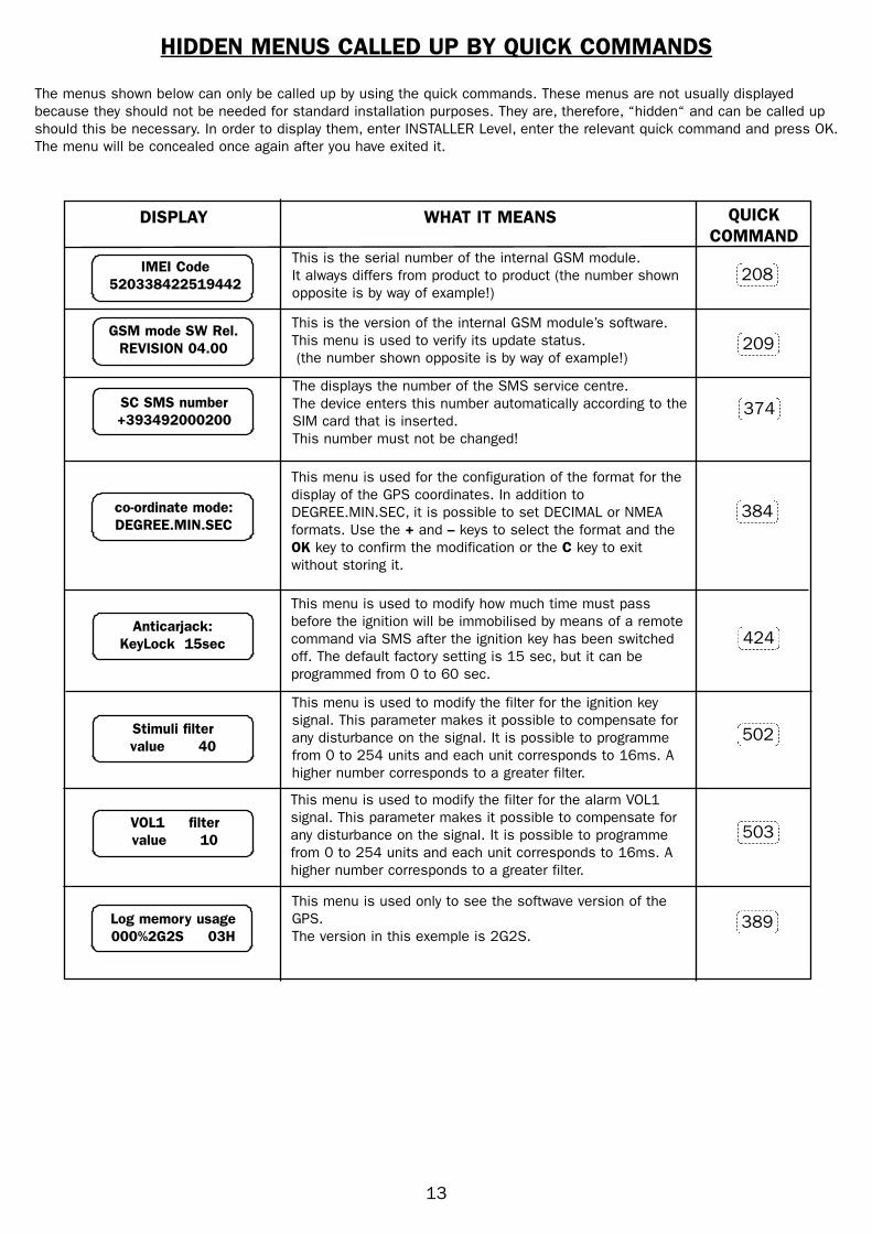
HIDDEN MENUS CALLED UP BY QUICK COMMANDS
The menus shown below can only be called up by using the quick commands. These menus are not usually displayed
because they should not be needed for standard installation purposes. They are, therefore, “hidden“ and can be called up
should this be necessary. In order to display them, enter INSTALLER Level, enter the relevant quick command and press OK.
The menu will be concealed once again after you have exited it.
This is the serial number of the internal GSM module.
It always differs from product to product (the number shown
opposite is by way of example!)
This is the version of the internal GSM module’s software.
This menu is used to verify its update status.
(the number shown opposite is by way of example!)
This menu is used only to see the softwave version of the
GPS.
The version in this exemple is 2G2S.
This menu is used for the configuration of the format for the
display of the GPS coordinates. In addition to
DEGREE.MIN.SEC, it is possible to set DECIMAL or NMEA
formats. Use the + and – keys to select the format and the
OK key to confirm the modification or the C key to exit
without storing it.
This menu is used to modify the filter for the ignition key
signal. This parameter makes it possible to compensate for
any disturbance on the signal. It is possible to programme
from 0 to 254 units and each unit corresponds to 16ms. A
higher number corresponds to a greater filter.
This menu is used to modify the filter for the alarm VOL1
signal. This parameter makes it possible to compensate for
any disturbance on the signal. It is possible to programme
from 0 to 254 units and each unit corresponds to 16ms. A
higher number corresponds to a greater filter.
This menu is used to modify how much time must pass
before the ignition will be immobilised by means of a remote
command via SMS after the ignition key has been switched
off. The default factory setting is 15 sec, but it can be
programmed from 0 to 60 sec.
208
209
389
384
502
503
424
DISPLAY WHAT IT MEANS QUICK
COMMAND
13
IMEI Code
520338422519442
GSM mode SW Rel.
REVISION 04.00
Log memory usage
000%2G2S 03H
co-ordinate mode:
DEGREE.MIN.SEC
Anticarjack:
KeyLock 15sec
Stimuli filter
value 40
VOL1 filter
value 10
The displays the number of the SMS service centre.
The device enters this number automatically according to the
SIM card that is inserted.
This number must not be changed!
SC SMS number
+393492000200374

14
VEHICLE CONSIGNMENT
CUSTOMIZING THE PASSWORDS
After completing installation, for safety reasons, you must alter the passwords to access the various levels in the Sat
Programmer. This will allow the product to be used and programmed only by authorised personnel in possession of the
correct access codes.
The passwords for the UNBLOCKED and UNBLOCK FUNCTIONS levels must be keyed in by the vehicle’s owner alone.
These passwords must remain confidential. The installer must key in his own secret password.
In this way, the user (if provided with the Sat Programmer) will only be able to access certain utility levels, such as
phonebook management, but will not be able to alter any parameters that are fundamental for the correct operation of the
device. In the same way, the installer cannot access the product unless it is first disarmed by the owner by means of his
password.
It is possible to access all the menus for the modification of the passwords from INSTALLER level.
This is the UNBLOCKED level password. The default setting
is 11111 but it will be displayed as asterisks at installer
level for a question of confidentiality.
The password can be any number with 5 to 8 digits
This is the UNBLOCK FUNCTIONS level password. The
default setting is 33333 but it will be displayed as asterisks
at installer level for a question of confidentiality.
The password can be any number with 5 to 8 digits.
This is the INSTALLER level password. The default setting is
44444. The number is displayed since there is no need for
confidentiality since it is the installer’s own number. The
password can be any number with 5 to 8 digits
Installer
code>> 12345678NB: The code must be a number composed
of 5 to 8 digits.
200
300
202
Installer
code>> 44444
E.G. :
DISPLAY WHAT IT MEANS QUICK
COMMAND
Installer OK
Select function :
Enter new code
OK to storeC to cancel
Unlock
code>> ********
Function Enable
code>> ********
Installer
code>> 44444
15
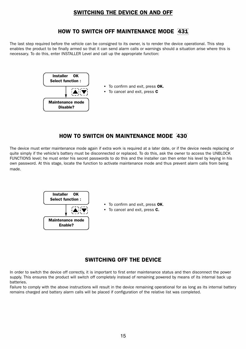
SWITCHING THE DEVICE ON AND OFF
HOW TO SWITCH OFF MAINTENANCE MODE 431
The last step required before the vehicle can be consigned to its owner, is to render the device operational. This step
enables the product to be finally armed so that it can send alarm calls or warnings should a situation arise where this is
necessary. To do this, enter INSTALLER Level and call up the appropriate function:
HOW TO SWITCH ON MAINTENANCE MODE 430
The device must enter maintenance mode again if extra work is required at a later date, or if the device needs replacing or
quite simply if the vehicle’s battery must be disconnected or replaced. To do this, ask the owner to access the UNBLOCK
FUNCTIONS level; he must enter his secret passwords to do this and the installer can then enter his level by keying in his
own password. At this stage, locate the function to activate maintenance mode and thus prevent alarm calls from being
made.
SWITCHING OFF THE DEVICE
In order to switch the device off correctly, it is important to first enter maintenance status and then disconnect the power
supply. This ensures the product will switch off completely instead of remaining powered by means of its internal back up
batteries.
Failure to comply with the above instructions will result in the device remaining operational for as long as its internal battery
remains charged and battery alarm calls will be placed if configuration of the relative list was completed.
Maintenance mode
Disable?
• To confirm and exit, press OK.
• To cancel and exit, press C
Maintenance mode
Enable?
• To confirm and exit, press OK.
• To cancel and exit, press C.
Installer OK
Select function :
Installer OK
Select function :