INSTALLER'S MANUAL - Thermann · INSTALLER'S MANUAL Gas Continuous Flow Water Heaters Models...
24
INSTALLER'S MANUAL Gas Continuous Flow Water Heaters Models 16NG50/16LP50 16NG60/16LP60 20NG50/20LP50 20NG60/20LP60 26NG50/26LP50 26NG60/26LP60 Installation Details Warranty
-
Upload
dangnguyet -
Category
Documents
-
view
219 -
download
0
Transcript of INSTALLER'S MANUAL - Thermann · INSTALLER'S MANUAL Gas Continuous Flow Water Heaters Models...

INSTALLER'S MANUALGas Continuous Flow Water Heaters
Models 16NG50/16LP50 16NG60/16LP60 20NG50/20LP50 20NG60/20LP60 26NG50/26LP50 26NG60/26LP60
Installation DetailsWarranty
17941_Thermann_Installers_Manual_5_Star_010715.indd 1 3/07/2015 3:19 pm

Thermann Installer's ManualGas Continuous Flow Water Heaters
17941_Thermann_Installers_Manual_5_Star_010715.indd 2 3/07/2015 3:19 pm

33
Important Safety Instructions 4
Electrical Connection 5
Introduction 6
Exploded Diagram of Unit 7
Dimensions 8
Technical Data 9
Cold Water Connection 10
Hot Water Connection 10
Gas Connection 11
Electrical Connection 11
Remote Controllers 12-18
Wiring Diagram and Remote Controls Installation Schematic 19
Fault Monitor 20
CONTENTS
17941_Thermann_Installers_Manual_5_Star_010715.indd 3 3/07/2015 3:19 pm

Thermann Installer's ManualGas Continuous Flow Water Heaters
4
Caution
PullNo wet hand
CloseClose
Danger
IMPORTANT SAFETY INSTRUCTIONSDO NOT INSTALL INDOORS
This unit is designed for outdoor installation and should never be installed indoors as this can cause oxygen deficiency and incomplete combustion.
CONFIRM TYPE OF GAS AND POWER SUPPLY
Make sure to use the gas type as well as power supply (voltage/frequency) as indicated on the label located on the cabinet side.
Natural Gas or Propane will be printed on the gas type label.
FREEZE PREVENTIONThis unit comes equipped with electric heaters that prevent the water heater from freezing.
To enable this freeze prevention system to operate there must be an electrical power supply connected to the unit.
The freeze prevention devices will not operate if the electrical power source is not connected.
The electric defrost heaters are installed inside the water heater only. All external hot and cold water supply pipes and fittings connected to the water heater should be properly insulated to prevent freezing.
SECURE SERVICE SPACE
Make sure there is enough space around the unit for checking, service and maintenance.
CloseClose
5
No Fire Prohibited
Check
WATCH FOR GAS LEAK
When gas leak is noticed, stop using the unit immediately and close the gas valve.
Warning
17941_Thermann_Installers_Manual_5_Star_010715.indd 4 3/07/2015 3:19 pm

555
ELECTRICAL CONNECTION
DO NOT REPLACE POWER CORD
If the power supply cord is damaged, it should be replaced by a cord available from your local Reece branch. The power cord must be replaced by an authorised tradesperson.
DO NOT USE POWER CORD BUNDLED
Never use power cord in a bundled condition. It can cause heat generation and fire.
DO NOT PULL POWER CORD
Do not remove the power plug by pulling the cord as it may generate heat by wire breakage and cause fire.
Hold the plug when removing the power cord.
INSERT POWER PLUG FULLY INTO POWERPOINT
Check that the power plug is clean and undamaged, then fully insert into the power point.
DANGER OF WET HANDS
Do not touch power plug with wet hands. It can cause electric shock.
5
5
5
5
Prohibited
Prohibited
Warning
Check
WARNING:For continued safety of this appliance it must be installed, operated and maintained in accordance with the manufacturer's instructions.
17941_Thermann_Installers_Manual_5_Star_010715.indd 5 3/07/2015 3:19 pm

Thermann Installer's ManualGas Continuous Flow Water Heaters
6
GENERAL
The Thermann Continuous Flow must be installed in accordance with the following:
(1) These instructions;
(2) National Construction Code and Local authority regulations;
(3) AS/NZS 3500.4 “Plumbing and Drainage - Heated Water Services”,
(4) The Australian standard for gas installations AS/NZS 5601;
(5) Any other statutory regulation that may apply;
(6) A notice of intention to install shall be lodged with the relevant local Gas Authority prior to installation.
DELIVERY INSPECTION
The Thermann Gas Continuous Flow hot water heater unit is supplied fully assembled and ready for installation.
The installer, upon delivery of the unit, should immediately remove all packing materials and inspect the unit for damage, and ensure that the unit supplied is correct for the gas supply to which it is to be connected. If any concerns, please report any damage or discrepancies to Reece, quoting the serial number and model number, which can be found on the outside of the cabinet.
INSTALLATION MUST BE CARRIED OUT ONLY BY AN AUTHORISED AND APPROPRIATELY LICENSED PERSON.
This product is an external electronic gas hot water heater.
These units are factory set to deliver 50°C or 60°C depending on the model purchased.
If the unit has a factory setting temperature higher than 50°C and is intended to deliver water directly to sanitary fixtures used primarily for the purposes of personal hygiene, it must be fitted with an approved tempering valve into the hot water piping to any bathroom and/or ensuite.
If the Thermann 26 model is for use as a solar booster, the setting temperature must be altered to 70°C (refer to the temperature setting instructions on the wiring diagram sheet which is attached to the unit, inside the front cover). For this application, these instructions must be read in conjunction with the Thermann solar hot water system technical (installation) manual.
Up to three optional remote controls can be provided for complete hot water temperature selection. If this option is used an approved temperature limiting device must be installed on any units with a delivery temperature above 50°C.
INTRODUCTION
THIS HOT WATER UNIT IS NOT FOR POOL OR SPA HEATING
17941_Thermann_Installers_Manual_5_Star_010715.indd 6 3/07/2015 3:19 pm

777
EXPLODED DIAGRAM OF UNITModel : 16/20
PARTS DESCRIPTION1. FLUE OUTLET
2. GAS VALVE
3. CIRCUIT BOARD
4. BURNER CASE
5. HOT WATER OUTLET
6. COLD WATER INLET
7. GAS SUPPLY INLET
8. HEAT EXCHANGER
Model : 26
PARTS DESCRIPTION1. FLUE OUTLET
2. GAS VALVE
3. CIRCUIT BOARD
4. BURNER CASE
5. HOT WATER OUTLET
6. COLD WATER INLET
7. GAS SUPPLY INLET
8. HEAT EXCHANGER
9. WATER VOLUME PROPORTIONAL VALVE
1
3
4
8
2
765
1
3
4
8
9
2
765
17941_Thermann_Installers_Manual_5_Star_010715.indd 7 3/07/2015 3:19 pm

Thermann Installer's ManualGas Continuous Flow Water Heaters
8
Model : 16/20
Model : 26
8.8
8
165 15
619
1357
5
350
50 50
585
330
COLD WATER INLET R1/2 /15
WATER INLET FILTER
PRESSURE RELIEF VALVE
GAS SUPPLY INLETR3/4 /20 HOT WATER OUTLET
R1/2 /15
CABLE ENTRY POINT
842531
12
330
R3/4 /20
R3/4 /20 R3/4 /20
623
1357
5
350
50 50
842535
8165 15
585
HOT WATER OUTLET
CABLE ENTRY POINT
COLD WATER INLET
WATER INLET FILTER
PRESSURE RELIEF VALVE
GAS SUPPLY INLET
8.8
8
165 15
619
1357
5
350
50 50
585
330
COLD WATER INLET R1/2 /15
WATER INLET FILTER
PRESSURE RELIEF VALVE
GAS SUPPLY INLETR3/4 /20 HOT WATER OUTLET
R1/2 /15
CABLE ENTRY POINT
842531
12
330
R3/4 /20
R3/4 /20 R3/4 /20
623
1357
5
350
50 50
842535
8
165 15
585
HOT WATER OUTLET
CABLE ENTRY POINT
COLD WATER INLET
WATER INLET FILTER
PRESSURE RELIEF VALVE
GAS SUPPLY INLET
DIMENSIONS
17941_Thermann_Installers_Manual_5_Star_010715.indd 8 3/07/2015 3:19 pm

999
TECHNICAL DATAMODEL 16 20 26
Nominal hourly gas consumption by proportional electronic gas control MJ/h 125 160 200
Test point pressure (NG) kPa 0.4 0.56 0.68
Test point pressure (Propane) kPa 0.4 0.61 0.7
Water heating capacity @ 40°C rise L/min 10 12.5 16.25
Minimum working pressure kPa 260 260 210
Maximum working pressure kPa 1200 1200 1200
Gas injectors diameter (NG) mm 1.35/1.65 1.35/1.65 1.34/1.65
Gas injectors diameter (Propane) mm 1.35/1.65 1.35/1.65 1.0/1.2
Input voltage single phase 50Hz V 240 240 240
Maximum output current A 0.42 0.45 0.47
Inlet gas connection male thread R3/4" (20mm) R3/4" (20mm) R3/4" (20mm)
Cold water connection male thread R1/2" (15mm) R1/2" (15mm) R3/4" (20mm)
Hot water connection male thread R1/2" (15mm) R1/2" (15mm) R3/4" (20mm)
Relief valve pressure setting kPa 1400 1400 1400
Weight dry kg 16 16 17
Dimensions (DxWxH) mm 165 x 350 x 575 165 x 350 x 575 165 x 350 x 575
SAIG Approval certificate no. GSCS20021. Watermark Certificate of compliance WMKA 00506
DATA PLATELeft outside of cabinet.
GAS TYPEThe gas label is located on the left outside of cabinet. The label will be either Natural Gas or Propane. The nominated gas is the gas that this appliance is designed to operate with. DO NOT OPERATE WITH ANY OTHER GAS TYPE.
WARNING LABELSLocated on the side of the cabinet. PLEASE READ THESE LABELS CAREFULLY.
INSTALLATION LOCATIONTHIS HEATER IS APPROVED FOR OUTDOOR INSTALLATION ONLY. IT IS NOT SUITABLE FOR INDOOR USE.Refer to AS/NZS 5601 for clearance requirements of flue termination. In addition, ensure that the appliance installation location permits easy access for maintenance and operation.
MOUNTING THE APPLIANCEThe heater must be installed by using a fixing method which is sufficient to support the weight of the unit. Refer to diagrams on page 8 for dimensions of mounting brackets and positions. The top bracket has a centre hole so that the appliance can be positioned by hanging it on one screw, then other screws can be secured.
17941_Thermann_Installers_Manual_5_Star_010715.indd 9 3/07/2015 3:19 pm

Thermann Installer's ManualGas Continuous Flow Water Heaters
10
COLD WATER SUPPLY TO WATER HEATERRefer to the Dimensions diagrams on page 8 for the position of connections.
Copper tube of a minimum size of 1/2" (15mm) for 16 and 20 models and 3/4" (20mm) for 26 model should be connected to the appliance.
The water inlet connections are R1/2" (15mm) male BSP for 16 and 20 models and R3/4" (20mm) male BSP for 26 model and require a union to allow for removal of the water heater.
Pipe sizing from the cold water supply should be sized according to local BY LAWS for water supply.
ISOLATING VALVE
A full flow isolation valve such as a gate valve or ball valve together with a disconnection union must be used on the cold water inlet to the water heater.
THIS REQUIREMENT IS AN AUSTRALIA WIDE REQUIREMENT UNDER THE NATIONAL PLUMBING CODE.
If the above instruction is not carried out, all warranties on the unit will be voided.
Stop taps or combination stop taps and non-return valves are not to be used.
NOTE: No pressure reduction valve is required unless the inlet water pressure exceeds 1400kPa at any time.
COLD WATER CONNECTION
Refer to Dimensions diagrams on page 8 for the position of connection.
The outlet connection is male thread R1/2" (15mm) for 16 and 20 models and R3/4" (20mm) for 26 and requires union connection to allow for removal of the unit.
Install the hot water supply line from the unit with copper tube with a minimum of 1/2" (15mm) for 16 and 20 models and R3/4" (20mm) for 26 model.
For units set at 50°C, a minimum of 4 metres of 20mm pipe must be run before the first outlet.
Keep the pipe lengths to a minimum and make sure that the pipework is well insulated, as correct performance of the appliance is dependent on properly insulated pipework.
DO NOT FIT ANY VALVES OR RESTRICTORS TO THE OUTLET OF THE WATER HEATER.
DO NOT FIT ANY OBSTRUCTION TO THE PRESSURE RELIEF LOCATED ON THE HOT WATER OUTLET CONNECTION.
After purging the air from the system using the hot water supply taps, remove the water inlet strainer located on the cold water supply inlet connection.
Remove any debris from the filter and replace. When replacing the filter do not over-tighten the “O”ring seal.
HOT WATER CONNECTION
17941_Thermann_Installers_Manual_5_Star_010715.indd 10 3/07/2015 3:19 pm

111111
GAS CONNECTION
ELECTRICAL CONNECTION
Fit a union to the water heater gas inlet for easy connection and removal. The thread diameter is R3/4" / (20mm).
THIS DOES NOT INDICATE THE SIZE OF THE GAS SUPPLY. Refer to AS/NZS 5601 for guidance on pipe sizing.
Fit an approved isolating gas valve and disconnection union into the supply line adjacent to the water heater gas connection.
Ensure that the supply pipe and the gas pressure regulator (Propane or Natural Gas) has sufficient flow capacity for this and other appliances connected to the fitting line.
For Propane appliances ensure that gas cylinders are of sufficient size. The water heater alone will require a regulator of 4KG per hour capacity.
Before connecting the appliance to the gas service, purge any debris or air from the gas service. Venting of purged gas must occur in an area free of sources of ignition.
Close the isolating gas valve prior to connection of the appliance.
After connection, check all joints for leaks with an approved leak tester.
Refer to AS/NZS 5601 Installation Code for pipe sizing details.
The Thermann 16/20/26 requires a minimum of 125/160/200 MJ/h respectively.
If the gas pipe sizing is insufficient, the customer will not obtain the full performance benefit. Gas pipe sizing must consider the gas input to this appliance as well as all the other gas appliances in the premises.
Service calls are chargeable for units installed with incorrect pipe sizes.
The appliance is equipped with a three pinned earthed plug to be connected to a 240V 50Hz power supply. The electrical rating of the appliance is 0.42/0.45/0.47Amp. for the Thermann 16/20/26 respectively.
The appliance requires a 240V 50Hz weatherproof power outlet installed in a protected position adjacent to the appliance.
IMPORTANT: The appliance should always be disconnected from the power supply before any maintenance is carried out.The installer must check appliance operation at the completion of installation.
TESTING THE WATER HEATER AFTER INSTALLATION IS COMPLETED.Turn on power supply to the heater and allow approximately 30 seconds for the computer to perform a safety check. Open a hot water tap and check the temperature of the hot water supplied. The burners will not light if the flow rate is less than 3L/min.IF THE UNIT FAILS TO OPERATE, CONSULT THE FAULT MONITOR (LAST PAGE).
Danger: In the case that the water piping is accidentally connected to gas connection port, all parts of gas circuit must be replaced. If the unit is operated without replacement, it may cause gas leakage, explosion or fire.
17941_Thermann_Installers_Manual_5_Star_010715.indd 11 3/07/2015 3:19 pm

Thermann Installer's ManualGas Continuous Flow Water Heaters
12
3. CONNECTION OF WIRING TO THE THERMANN UNIT1. Remove the front cover from the unit.
2. Install the wiring to the Thermann main unit using conduit or by concealing the wires in the wall cavity.
3. Install the wiring into the cabinet through the wiring access adjacent to the power cable.
4. Attach the wiring to the plate adjacent to the terminal block, using the cable clamp provided. Then attach the wires to the terminals for the remote controls. Replace the front cover of the water heater.
IMPORTANT
DO NOT locate the remote controls where they may come into contact with water.
DO NOT position the remote controls in the vicinity of chemicals.
DO NOT position the remote controls over a cooker, grill oven or toaster.
DO NOT position the remote controls where materials may spill onto them.
1. NUMBER OF CONTROLLERSOne, two or three remote control panels can be installed as optional extras.
2. CONTROLLER LOCATIONSThese controls are to be fitted in the following locations:
MAIN CONTROL - kitchen or laundry Model CMR-2254 BATHROOM CONTROL - main bathroom Model YST-2254 ENSUITE CONTROL - second bathroom Model YST-2254S
REMOTE CONTROLLERS
17941_Thermann_Installers_Manual_5_Star_010715.indd 12 3/07/2015 3:19 pm

131313
REMOTE CONTROLLERS
Remote ControllerConnection Terminals
Remote Controller Cable
Cable Clamp
Remote ControllerConnection Terminals
Remote Controller Cable
Cable Clamp
16/20 MODELS
26 MODEL
17941_Thermann_Installers_Manual_5_Star_010715.indd 13 3/07/2015 3:19 pm

Thermann Installer's ManualGas Continuous Flow Water Heaters
14
REMOTE CONTROLLERS
Installation
• Install conduit inside of wall in advance. Alternatively conceal wires inside wall cavity.
• Pass remote controller cables through conduit/wall cavity. Then pass the cables through the hole of the fitting bracket and pull them out.
• Attach the fitting bracket with screws.
• Connect the remote controller cables to the terminal on the rear of the controller.
• Fit controller to fitting bracket and secure.
4. INSTALLATION OF MAIN CONTROLLER Safety precautions
• Disconnect the heater from the power supply before connecting remote controller cables.
• Do not install the main remote controller above a heat source such as a hot plate or a kitchen range. The heat will cause electrical component problems, or deform the exterior.
• Do not install the main remote controller where it will be subjected to splashing water or steam from appliances.
• Do not install the main remote controller in a position that will be exposed to direct sunlight.
• Do not install the main remote controller where any commercial chemicals such as ammonia, sulfur, chlorine, ethylenic compound and acids etc are used.
• The remote controller cables carry low voltage, 12VDC.
Screw
Remote controllerfitting bracket
Hole for wiring
Cover
Cover
Screw
Detach right-and-left covers of the remote controller and fix them to the wall directly with screws. Then attach the covers again.
Chemicals
Do Not
17941_Thermann_Installers_Manual_5_Star_010715.indd 14 3/07/2015 3:19 pm

151515
5. INSTALLATION OF BATHROOM AND ENSUITE CONTROLLER
Safety precautions
• Before remote controller installation, check the hole position considering wall stud location.
• Note: Do not dismantle the remote controller due to water-proof design.
• Do not install remote controller where water will contact the remote controller directly.
• The remote controller cables carry low voltage, 12VDC digital.
Installation
• Drill a 12mm hole in a wall for the remote controller cables.
• Feed controller cable to controller wall location. Pull cable end connector through hole.
• After passing the remote controller cables through the hole. Connect to the quick connector on rear of controller and feed spare cable back into wall. Remove backing paper from adhesive pad on rear of remote controller. Then attach the remote controller to the wall.
• Detach both end covers of remote controller and fix the remote controller to the wall with screws (2pcs) in the screw holes provided. Do not tighten the screws excessively, as the screw hole may be damaged. In case of mounting the remote controller on tile, cement or mortar, use appropriate wall anchors. Then attach covers again.
Remote controller adhesive pad
Remote controller cables
Screw
Cover
Cover
Wall anchor
Remote controller cables
REMOTE CONTROLLERS
17941_Thermann_Installers_Manual_5_Star_010715.indd 15 3/07/2015 3:19 pm
Thermann Installer's ManualGas Continuous Flow Water Heaters
16
REMOTE CONTROLLERS6. COMMISSIONING AND TESTINGAfter completing the installation of the unit, turn the water, power and gas supplies on to the unit.
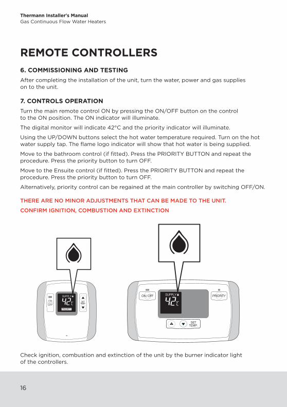
7. CONTROLS OPERATIONTurn the main remote control ON by pressing the ON/OFF button on the control to the ON position. The ON indicator will illuminate.
The digital monitor will indicate 42°C and the priority indicator will illuminate.
Using the UP/DOWN buttons select the hot water temperature required. Turn on the hot water supply tap. The flame logo indicator will show that hot water is being supplied.
Move to the bathroom control (if fitted). Press the PRIORITY BUTTON and repeat the procedure. Press the priority button to turn OFF.
Move to the Ensuite control (if fitted). Press the PRIORITY BUTTON and repeat the procedure. Press the priority button to turn OFF.
Alternatively, priority control can be regained at the main controller by switching OFF/ON.
THERE ARE NO MINOR ADJUSTMENTS THAT CAN BE MADE TO THE UNIT.
CONFIRM IGNITION, COMBUSTION AND EXTINCTION
Check ignition, combustion and extinction of the unit by the burner indicator light of the controllers.
17941_Thermann_Installers_Manual_5_Star_010715.indd 16 3/07/2015 3:19 pm

171717
CMR-2254(Main remote Controller)
This remote controller is intended to be used in the kitchen, laundry room or utility area.
Digital MonitorIndicates the selected water temperature. Error messages flash in the event of a failure.
ON IndicatorIndicates power is on to the system.
ON/OFF ButtonPower switch to operate this control.
PRIORITY IndicatorIndicates this controller has priority control over the other controller.
Flame Logo IndicatorIndicates that a hot water faucet is open and that control of the temperature is by another controller.
UP/DOWN ButtonIncrease or decrease the desired water temperature.
REMOTE CONTROLLERS
17941_Thermann_Installers_Manual_5_Star_010715.indd 17 3/07/2015 3:19 pm

Thermann Installer's ManualGas Continuous Flow Water Heaters
18
REMOTE CONTROLLERSYST-2254 Bathroom Controller
YST-2254S Ensuite Controller
These remote controllers are intended for installation in the bathroom and ensuite.
ON IndicatorIndicates power is on to the system.
ON/OFF ButtonPower switch to operate this control.
Digital MonitorIndicates the selected water temperature. Error messages flash in the event of failure.
Flame Logo IndicatorIndicates that a hot water faucet is open and that control of the temperature is by another controller.
UP/DOWN ButtonIncrease or decrease the desired water temperature.
PRIORITY ButtonPRIORITY Button to set the water temperature on Bathroom remote controller.
PRIORITY IndicatorIndicates this controller has priority control over by controller.
17941_Thermann_Installers_Manual_5_Star_010715.indd 18 3/07/2015 3:19 pm

191919
PY
BK
G
BL
OR
GR
BR
WW
WW
W
WW
WW W BRBL
G
G/Y
PROTECTORSURGE
250VT5A
12
FUSE
11
AC240V
W
: Purple: Yellow
: Black
: Green
: Blue
: Orange: Red
: Grey
: Brown
: White
IGNITOR
SPARK ELECTRODE
6
BKBK
BKBK
BKBK
8G
W
YBL
R
OFAN MOTOR
REMOTECONTROLLER
2
1
4
3
5
9
WATER FLOW SENSOR BK
GR
GR
R
W
GAS VALVE(CONTROL) 10
DIP SWITCH
OW
P
BKG
Y
ON
MIN.
GC-156
MIN.MIN
MA
X
BLR
5
76
1
4
2
8
3
OFF
WATER FLOWCONTROL VALVE
Y
Y
THERMAL FUSE
GAS VALVE 2BL
O
Y
GAS VALVE 1
Y
GAS VALVE(MAIN)
YY Y
W
BK
BLBK
AUTOTRANSFORMER
THERMOSTAT(ANTI-FROST)
ANTI-FROST HEATERS
250VT3.15A
ONLY FOR 26NG/26LP
FAN MOTOR FUSE
WW
BLBL
WW
WW
PCBPCB NO.
26NG GC-154
16NG
GC-155
MODELNAME
26LP
16LP20NG20LP
W
YY
FLAME ROD
(OVER HEAT)
TEMPERATURE SENSOR(OUTGOING TEMP.)
THERMOSTAT
TEMPERATURE SENSOR(INCOMING TEMP.)
WIRING FROM MAIN UNIT TO MAIN & BATHROOM/ENSUITE REMOTE CONTROLS
BATHROOM CONTROL
MAIN CONTROL
ENSUITE CONTROL
240volt POWER SUPPLY
WIRING DIAGRAM AND REMOTE CONTROLS INSTALLATION SCHEMATIC
17941_Thermann_Installers_Manual_5_Star_010715.indd 19 3/07/2015 3:19 pm

Thermann Installer's ManualGas Continuous Flow Water Heaters
20
When installed with remote controllers the unit has a self diagnosing function for faults.
When the unit does not operate correctly an error code is displayed on the MAIN and BATHROOM or ENSUITE remote controls TEMPERATURE DISPLAY INDICATOR.
The cause of the fault can be determined after checking the fault numbers display on the remote control display.
DISPLAY PROBLEM REMEDY
111 GAS BURNER FAILS TO IGNITE CHECK GAS SUPPLY
721 FALSE FLAME DETECTIONCALL REECE CUSTOMER CARE 1800 080 055
121 LOSS OF COMBUSTIONCHECK GAS SUPPLY AND PRESSURE
141 RESIDUAL FLAME SAFETY DEVICECALL REECE CUSTOMER CARE 1800 080 055
311, 321 THERMISTOR WIRE BREAKAGECALL REECE CUSTOMER CARE 1800 080 055
611 COMBUSTION FAN FAILURECALL REECE CUSTOMER CARE 1800 080 055
740/750/760 COMMUNICATION FAILURE BETWEEN REMOTE CONTROLS & PCB.
TURN OFF POWER AND TURN ON AGAIN
FAULT MONITOR
17941_Thermann_Installers_Manual_5_Star_010715.indd 20 3/07/2015 3:19 pm

212121
17941_Thermann_Installers_Manual_5_Star_010715.indd 21 3/07/2015 3:19 pm

Thermann Installer's ManualGas Continuous Flow Water Heaters
22
17941_Thermann_Installers_Manual_5_Star_010715.indd 22 3/07/2015 3:19 pm

232323
17941_Thermann_Installers_Manual_5_Star_010715.indd 23 3/07/2015 3:19 pm

20732921 (K)
17941_Thermann_Installers_Manual_5_Star_010715.indd 24 3/07/2015 3:19 pm