
INSTALLER: Leave this manual with the appliance. … any pressure testing of that system at ... Any...
48
INSTALLER: Leave this manual with the appliance. CONSUMER: Retain this manual for future eference.
Transcript of INSTALLER: Leave this manual with the appliance. … any pressure testing of that system at ... Any...

INSTALLER: Leave this manual with the appliance. CONSUMER: Retain this manual for future eference.

2
AVERTISSEMENT: Assurez-vous de bien suivre
les instructions données dans cette notice pour
réduire au minimum le risque d’incindie ou
d’explosion ou pour éviter tout dommage
matériel, toute blessure ou la mort.
- Ne pas entreposer ni utilizer d’essence ni
d’autres vapeurs ou liquides inflammables dans
le voisinage de cet appareil ou de tout autre
appareil.
- QUE FAIRE SI VOUS SENTEZ UNE ODEUR DE
GAZ:
Ne pas tenter d’allumer d’appareil.
Ne touchez à aucan interrupteur. Ne pas
vous servir des téléphones se trouvant
dans le bâtiment où vous trouvez.
Appelez immédiatement votre
fournisseur de gaz depuis un voisin.
Suivezles instructions du fournisseur.
Si vous ne pouvez rejoindre le fournisseur
de gaz, appelez le service des incindie.
- L’installation et l’entretien doivent être assurés
par un installateur ou un service d’entretien
qualifié ou par le fournisseur de gaz.
Cet appareil peut être installé dans une maison
préfabriquée (mobile) déjà installée à demeure
si kes règlements locaux le permettent.
Cet appareil doit être uniquement avec las type
de gaz indiqué sur la plaque signalétique. Cet
appareil ne peut être converti à d’autres gaz,
sauf si une trousse de conversion est utilisée.
Ne pas utiliser cet appareils’il a été plongé,
meme partiellement, dans l’eau. Appeler un
technician qualifié pour inspecter l’appareail et
remplacer toute partie du système de commande
et toute commande qui a été plongée dans /’eau.
Attention. Au moment de l’entretien des com-
mandes, étiquetez tous les fils avant de les dé-
brancher. Des erreurs de la câblage peuvent en-
traîner un fonctionnement inadequate et dan-
gereux.
S’assurer que l’appareil fonctionne adéquate-
ment une fois l’entretien terminé.
AVERTISSEMENT. Ne pas utiliser l’appareil
si le panneau frontal en verre n’est pas en place,
est craqué ou brisé. Confiez le remplacement du
panneau à un technician agree.
INSTALLATEUR: Laissez cette notice avec l’appareil. COMSOMMATEUR: Conservez cette notice pour consultation ultérieur.

3
IMPORTANT SAFETY INFORMATION 4
SPECIFICATIONS 5
INSTALLATION REQUIREMENTS 6
MASSACHUSETTS REQUIREMENTS 7
VENTING 8
ASSEMBLY & INSTALLATION 16
GAS CONNECTION 20 & 26
LIGHTING AND OPERATION 32
MAXITROL CONTROL SYSTEM 34
MAINTENANCE 40
MAINTENANCE LOG FORMS 42
REPLACEMENT PARTS LIST 43
CONTROL SCHEMATIC 44
INSTALLATION RECORD FORM 45
WARRANTY INFORMATION 46
TABLE OF CONTENTS
WE STRONGLY SUGGEST THAT YOU READ THIS MANUAL THOROUGHLY BEFORE BE-
GININNG THE INSTALLATION OF THE DIRECT VENT GAS FIREPLACE. AL-
THOUGH THE BASIC REQUIREMENTS FOR THE INSTALLATION OF ALL DIRECT VENT
GAS FIREPLACES ARE SIMILAR, EACH SPECIFIC PRODUCT HAS ITS OWN UNIQUE SET-
UP AND INSTALLATION REQUIREMENTS THAT MUST BE FOLLOWED EXACTLY. PLAN
YOUR INSTALLATION IN ADVANCE BY CAREFULLY REVIEWING ALL THE INFORMA-
TION CONTAINED IN THIS MANUAL.

4
IMPORTANT SAFETY INFORMATION
The installation must conform with local codes or, in the absence of local codes, with the National Fuel
Gas Code, ANSI Z223.1 or the Canadian Installation Code, CAN/CGA B149.
A manufactured home (USA only) or mobile home OEM installation must conform with the Manufactured
Home Construction and Safety Standard, Title 24 CFR, Part 3280 or when such a standard is not applica-
ble, the Standard for Manufactured Home Installations, ANSI/BCSBCS A225.1, or Standard for Gas
Equipped Recreational Vehicles and Mobile Housing, CSA Z240.4.
The appliance and its appliance main gas valve must be disconnected from the gas supply piping system
during any pressure testing of that system at test pressures in excess of 1/2 psi (3.5 kPa).
The appliance must be isolated from the gas supply piping system by closing its equipment shutoff valve
during any pressure testing of the gas supply piping system at test pressures equal to or less than 1/2 psi (3.5
kPa).
The installation must provide for adequate ventilation air to the appliance.
This gas appliance must not be connected to a chimney flue serving a separate solid-fuel burning appliance.
The appliance, when installed, must be electrically grounded in accordance with local codes, or, in the
absence of local codes, with the National Electrical Code ANSI/NFPA 70, or the Canadian Electrical Code,
CSA C22. 1.
The appliance area must be kept clear and free from combustible materials, gasoline and other flammable
vapors and liquids.
The flow of combustion and ventilation air must not be obstructed.
Do not use this appliance if any part has been under water. Immediately call a qualifed service technician
to inspect the appliance and to replace any part of the control system and any gas control which has been
under water.
Due to high temperatures, the appliance should be located out of traffic and away from furniture and
draperies.
Children and adults should be alerted to the hazards of high surface temperatures and should stay away to
avoid burns or clothing ignition.
Young children should be carefully supervised when they are in the same room as the appliance.
Clothing or other flammable material should not be placed on or near the appliance.
Any screen or guard removed for servicing an appliance must be replaced prior to operating the appliance.
Installation and repair should be done by a qualified service person. The appliance should be inspected
before use and at least annually by a professional service person. More frequent cleaning may be required
due to excessive lint from carpeting, bedding material, etc. It is imperative that the control compartments,
burners and circulating air passageways of the appliance be kept clean.
WARNING: Do not operate the appliance with the glass door assembly removed, or if the glass is
cracked or broken. Replacement of the glass should be done by a qualified service
person.
WARNING: Use only glass assembly, P/N 26-510 which includes the glass panel, frame and gasket.
Do not use substitute materials. Do not strike or slam the glass front. Do not use
abrasive cleaners. Do not clean when hot.
5
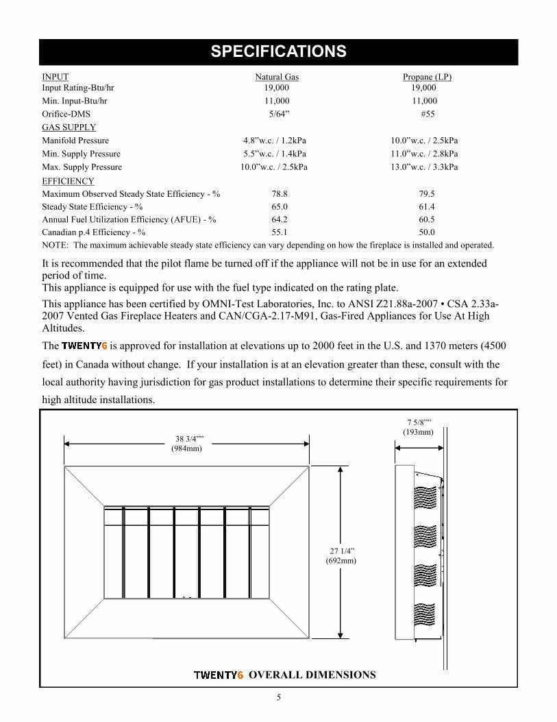
SPECIFICATIONS
INPUT Natural Gas Propane (LP)
Input Rating-Btu/hr 19,000 19,000
Min. Input-Btu/hr 11,000 11,000
Orifice-DMS 5/64” #55
GAS SUPPLY
Manifold Pressure 4.8”w.c. / 1.2kPa 10.0”w.c. / 2.5kPa
Min. Supply Pressure 5.5”w.c. / 1.4kPa 11.0”w.c. / 2.8kPa
Max. Supply Pressure 10.0”w.c. / 2.5kPa 13.0”w.c. / 3.3kPa
EFFICIENCY
Maximum Observed Steady State Efficiency - % 78.8 79.5
Steady State Efficiency - % 65.0 61.4
Annual Fuel Utilization Efficiency (AFUE) - % 64.2 60.5
Canadian p.4 Efficiency - % 55.1 50.0
NOTE: The maximum achievable steady state efficiency can vary depending on how the fireplace is installed and operated.
It is recommended that the pilot flame be turned off if the appliance will not be in use for an extended period of time. This appliance is equipped for use with the fuel type indicated on the rating plate.
This appliance has been certified by OMNI-Test Laboratories, Inc. to ANSI Z21.88a-2007 • CSA 2.33a-2007 Vented Gas Fireplace Heaters and CAN/CGA-2.17-M91, Gas-Fired Appliances for Use At High Altitudes.
The is approved for installation at elevations up to 2000 feet in the U.S. and 1370 meters (4500
feet) in Canada without change. If your installation is at an elevation greater than these, consult with the
local authority having jurisdiction for gas product installations to determine their specific requirements for
high altitude installations.
27 1/4”
(692mm)
38 3/4””
(984mm)
7 5/8””
(193mm)
OVERALL DIMENSIONS

6
INSTALLATION REQUIREMENTS
MINIMUM CLEARANCES TO COMBUSTIBLE CONSTRUCTION
Fireplace to L. Side Wall 6” (152mm) Fireplace to Ceiling 8” (203mm)
Fireplace to R. Side Wall 6” (152mm) Fireplace to Rear Wall 0” (0mm)*
Fireplace to Corner Wall 6” (152mm) Fireplace to Floor 3” (76mm)**
Vent Pipe to Adjacent Materials 1.5” (38mm)
*Mounting plate bosses contact the wall
**The minimum required clearance to be maintained from the fireplace to combustible flooring is meas-
ured from the top surface of carpeting, tile, etc.
Several issues must be addressed when selecting a suitable location for your fireplace. The mini-
mum clearances to combustible construction are listed below. In addition, access to the gas supply must be
considered. The location of the fireplace will also affect the venting requirements and you must be certain
the location will allow compliance with the venting requirements shown on page 8. You must also insure
that your installation provides adequate accessibility clearance for servicing and proper operation.
Installation and repair should be done by a qualified service person. The appliance should be inspected
before use and at least annually by a professional service person. More frequent cleaning may be required
due to excessive lint from carpeting, bedding material, etc. It is imperative that the control compartment,
burners and circulating air passageways of the appliance be kept clean.
CORNER (SHOWN USING OPTIONAL CORNER KIT)
WALLS
A = 6” (152mm)
B = 6” (152mm)
B B
A A
C = 8” (203mm)
D = 3” (76mm)
CEILING
C
FLOOR D
E = 5/16” (8mm)
WALL E
AIR SPACE BEHIND MOUNTING PLATE

7
INSTALLATION REQUIREMENTS
The gas fireplace is shipped with a 3/8” tube OD (male) connection. The gas supply piping should have a
separate gas shutoff valve and a 1/8” NPT plugged tapping upstream of the valve. The stove and its main
control valve must be disconnected from the gas supply piping system during any pressure testing of that
system at test pressures in excess of 1/2 psi (3.5 kPa). The stove must be isolated from the gas supply pip-
ing system by closing the main control valve during any pressure testing of the gas supply system at test
pressures equal to or less than 1/2 psi (3.5 kPa). After the gas supply has been connected, use a commercial
gas leak detector or apply a soapy water solution to all the fittings to check for gas leaks. Never use a
flame to test for leaks.
REQUIREMENTS FOR THE COMMONWEALTH OF MASSACHUSETTS
This product must be installed by a licensed plumber or gas fitter when installed within the Com-
monwealth of Massachusetts. If this appliance is installed in a dwelling, building or structure used in
whole or in part for residential purposes and the installation includes a horizontal vent termination
that is less than seven (7) feet above the finished grade in the area of the venting, including but not
limited to decks and porches, a hard-wired carbon monoxide detector with an alarm and battery
back-up must be installed on the floor level of the dwelling, building or structure where the appli-
ance is to be installed.
Additionally, a hard-wired or battery operated carbon monoxide detector with an alarm must be in-
stalled on each additional level of the dwelling, building or structure served by the appliance. It shall
be the responsibility of the property owner to secure the services of qualified licensed professionals
for the installation of hard-wired carbon monoxide detectors.
In the event that the horizontally vented appliance is installed in a crawl space or attic, the hard-
wired carbon monoxide detector with alarm and battery back-up may be installed on the next adja-
cent floor level.
In the event that this requirement cannot be met at the time of completion of the installation of the
appliance, the owner shall have a period of thirty (30) days to comply with the requirement. How-
ever, during said thirty (30) day period, a battery operated carbon monoxide detector with alarm
must be installed.
Each carbon monoxide detector as required in accordance with the above provisions must comply
with NFPA 720 and be ANSI/UL 2034 and IAS certified.
In addition when the vent termination is less than seven (7) feet above finished grade a metal or plas-
tic identification plate must be permanently mounted to the exterior of the building at a minimum
height of eight (8) feet above grade directly in line with the exhaust vent terminal. The sign shall
read, in print size no less than one-half (1/2) inch in size, “GAS VENT DIRECTLY BELOW. KEEP
CLEAR OF ALL OBSTRUCTIONS”.
A COPY OF THESE INSTRUCTIONS PLUS ALL VENTING INSTRUCTIONS WHICH IN-
CLUDE PARTS LISTS, AND/OR ALL VENTING DESIGN INSTRUCTIONS MUST REMAIN
WITH THE STOVE AT THE COMPLETION OF THE INSTALLATION.
ATTENTION INSTALLERS: Mark below which venting system was used in the installation. These
instructions must remain with the Installation & Operation Manual.
Simpson DuraVent GS/PRO®
Selkirk Direct-Temp®
Security Secure Vent™
AmeriVent Direct™ Metal Fab Direct Vent ICC Direct Vent

8
VENTING
The Direct Vent Gas Fireplace has been tested and listed for installation with 4” X 6 5/8” Simp-
son DuraVent GS/Pro®, Selkirk Direct-Temp®
, Security Secure Vent™, AmeriVent Direct™, Metal Fab Direct
Vent and ICC EXCELDirect venting components. Although you may use the pipe components (straight pipe,
elbows, etc.) from any of the listed manufacturers, you may only use the vent terminations (caps) listed in
the chart on page 9. For installations where a snorkel is needed, please note that only three snorkels are ap-
proved for use. Please plan your installation accordingly.
For all specific venting installation requirements, follow the installation instructions included by the venting
manufacturer with the venting system components you have chosen.
Please note:
For venting configurations that include no vertical rise, a total horizontal vent run of up to 30 inches
(and including one 45° elbow) is allowed. However, if your installation has room to add a vertical pipe
section, we suggest adding at least one foot of vertical rise to the system.
For venting configurations that include vertical rise, it is assumed that the installation will include at
least one 90° elbow. Up to three additional 90° elbows (or equivalent 45° elbows) may also be used.
The total venting may not exceed 20 feet of vertical rise and/or 10 feet horizontal run. Refer to the
venting charts starting on pages 10 & 11 for specific details while you plan your installation. Note:
The number of elbows impacts the maximum allowable horizontal vent run.
Many installations will involve venting directly through standard 2 X 4 or 2 X 6 construction exterior
wall to a horizontal vent termination (cap). The vent starter pipe has been designed to accommodate
those two common installations without the use of any additional venting components other than a stan-
dard horizontal cap. See the chart on page 9 for a list of approved vent caps.
A special corner installation kit (Part Number CK-26-1) is also available that will allow the
fireplace to be mounted in a corner without constructing a 45° partition wall. This kit is available from
your dealer and has its own installation instructions. Please refer to those instructions for
specific details regarding the installation using the kit.
If the fireplace will be installed on an interior wall or other location that precludes venting directly
through an outside wall to a horizontal vent cap, or if the distance to the outside wall exceeds 30”, one
or more elbows will be required to allow addition of the required vertical venting to the installation.
When vertical venting is required, the fireplace venting may be terminated with either a vertical or hori-
zontal vent cap depending on the specifics of the installation. Refer to the venting charts starting on
pages 10 & 11 for specific venting requirements and see the chart on page 9 for a list of approved vent
caps before you plan your installation.
A minimum clear space of 1 1/2” must be maintained around the vent pipe where it penetrates the first
combustible wall adjacent to the fireplace (either the outside wall for the direct-through-the-wall instal-
lation or the partition wall for the 45° or other interior wall installations). The special vent pipe heat
shields that are provided with the must also be installed in the first wall adjacent to the fire-
place. A minimum clear space of 1 1/2” must also be maintained where the vent pipe penetrates any
other interior wall, exterior wall, ceiling or roof.
The may also be installed in front of an exiting fireplace opening utilizing special co-linear
venting components available from the venting manufacturers. These systems split and then recombine
the co-axial air and exhaust and allow the use of flexible venting. This makes it easier to run the vent-
ing through the narrow fireplace damper opening to the top of the chimney. Refer to the vent manufac-
turers’ instructions. Use the vertical venting column (0 feet Horizontal Run) in the venting charts to
determine the required restrictor settings depending on the height of chimney.

9
Just as with any other vented device, vertical vent rise creates draft (negative pressure) in the firebox as the
exhaust gases heat up. If this draft becomes excessive, it can affect the performance or appearance of the
fire. The fireplace includes air and exhaust restrictors that are used to balance the draft in the
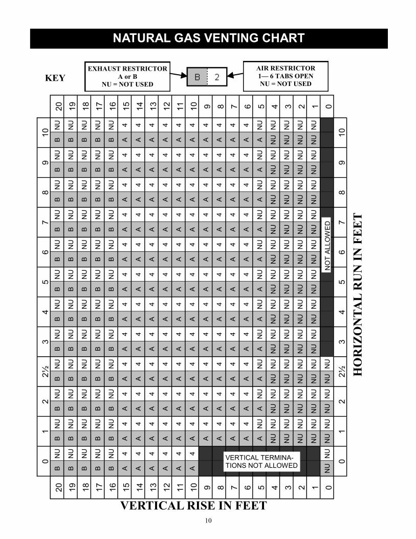
fireplace to the optimal level for installations where excessive draft might occur. The venting charts on
pages 10 and 11 provide an easy means for determining whether your specific installation requires inlet air
or exhaust restrictors or both. To make the determination about whether air or exhaust restrictors are
needed, a venting chart worksheet is provided on page 12. Follow the instructions and fill in the worksheet
for your particular installation. This will allow you to determine the recommended restrictor settings for
your exact installation. Although this might appear to be a complicated process at first glance, it is really
quite straight-forward and the result will be a fire that looks and performs as intended. Several examples
of worksheet calculations are shown on page 13 to help guide you.
Please be sure to note that:
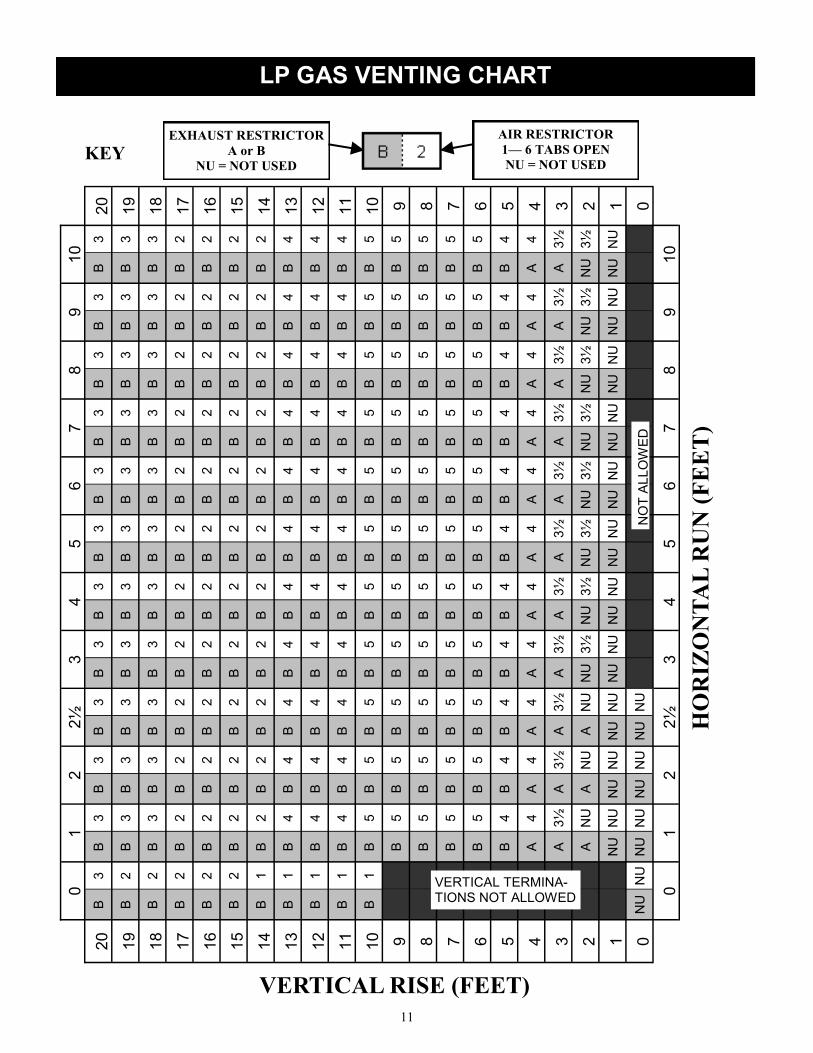
1. There are separate venting charts for Natural Gas and LP Gas. Refer to the appropriate chart for your
fuel type to determine your specific restrictor requirements. The settings in the charts have been deter-
mined based on extensive testing.
2. Determine the total vertical vent rise and total horizontal vent run for your installation. All measure-
ments are made from the center of the vent opening in the back of the fireplace.
3. If your fireplace will not be venting directly though an outside wall to a horizontal termination or if
more than 30” of horizontal vent run is required, some vertical vent rise will be required for the fire-
place to function and vent properly. Elbows will also be required for those installations. However, in-
stallations are limited to a maximum of four 90° elbows (or 45° elbow equivalents).
4. Note: Two 45° elbows equal one 90° elbow.
5. The recommended restrictor settings in the venting charts allow up to two 90° elbows (or 45° elbow
equivalents) to be used without affecting the restrictor settings. Additional elbows will require that you
calculate a new equivalent horizontal run for your installation to account for the additional flow resis-
tance caused by the extra elbows. For the purposes of calculating the equivalent horizontal vent run,
each additional 90° elbow is equivalent to three feet of horizontal vent run. The total horizontal vent
run including elbow equivalents can not exceed 10 feet.
6. The maximum vertical vent rise can not exceed 20 feet.
7. There are two exhaust restrictors that are provided with your fireplace. They are labeled
“A” and “B”. The A restrictor provides less exhaust restriction than B.
8. An air restrictor plate is also provided with your fireplace. It is a ring with bendable tabs that can be
set to adjust the amount of restriction in the air supply system. Once the appropriate number tabs are
bent open (in accordance with the requirements for your installation), the plate is inserted between the
fireplace and the vent starter pipe.
USING THE VENTING CHARTS
The location of the vent termination must meet the requirements of the current edition of ANSI Z223.1/
NFPA 54, National Fuel Gas Code or CAN B419.1, Natural Gas and Propane Installation Code and the
requirements shown on page 15 of this manual.
10
0
1
2
2
½
3
4
5
6
7
8
9
10
20
B
NU
B
N
U
B
NU
B
N
U
B
NU
B
N
U
B
NU
B
N
U
B
NU
B
N
U
B
NU
B
N
U
20
19
B
NU
B
N
U
B
NU
B
N
U
B
NU
B
N
U
B
NU
B
N
U
B
NU
B
N
U
B
NU
B
N
U
19
18
B
NU
B
N
U
B
NU
B
N
U
B
NU
B
N
U
B
NU
B
N
U
B
NU
B
N
U
B
NU
B
N
U
18
17
B
NU
B
N
U
B
NU
B
N
U
B
NU
B
N
U
B
NU
B
N
U
B
NU
B
N
U
B
NU
B
N
U
17
16
B
NU
B
N
U
B
NU
B
N
U
B
NU
B
N
U
B
NU
B
N
U
B
NU
B
N
U
B
NU
B
N
U
16
15
A
4
A
4
A
4
A
4
A
4
A
4
A
4
A
4
A
4
A
4
A
4
A
4
15
14
A
4
A
4
A
4
A
4
A
4
A
4
A
4
A
4
A
4
A
4
A
4
A
4
14
13
A
4
A
4
A
4
A
4
A
4
A
4
A
4
A
4
A
4
A
4
A
4
A
4
13
12
A
4
A
4
A
4
A
4
A
4
A
4
A
4
A
4
A
4
A
4
A
4
A
4
12
11
A
4
A
4
A
4
A
4
A
4
A
4
A
4
A
4
A
4
A
4
A
4
A
4
11
10
A
4
A
4
A
4
A
4
A
4
A
4
A
4
A
4
A
4
A
4
A
4
A
4
10
9
A
4
A
4
A
4
A
4
A
4
A
4
A
4
A
4
A
4
A
4
A
4
9
8
A
4
A
4
A
4
A
4
A
4
A
4
A
4
A
4
A
4
A
4
A
4
8
7
A
4
A
4
A
4
A
4
A
4
A
4
A
4
A
4
A
4
A
4
A
4
7
6
A
4
A
4
A
4
A
4
A
4
A
4
A
4
A
4
A
4
A
4
A
4
6
5
A
NU
A
N
U
A
NU
A
N
U
A
NU
A
N
U
A
NU
A
N
U
A
NU
A
N
U
A
NU
5
4
NU
N
U
NU
N
U
NU
N
U
NU
N
U
NU
N
U
NU
N
U
NU
N
U
NU
N
U
NU
N
U
NU
N
U
NU
N
U
4
3
NU
N
U
NU
N
U
NU
N
U
NU
N
U
NU
N
U
NU
N
U
NU
N
U
NU
N
U
NU
N
U
NU
N
U
NU
N
U
3
2
NU
N
U
NU
N
U
NU
N
U
NU
N
U
NU
N
U
NU
N
U
NU
N
U
NU
N
U
NU
N
U
NU
N
U
NU
N
U
2
1
NU
N
U
NU
N
U
NU
N
U
NU
N
U
NU
N
U
NU
N
U
NU
N
U
NU
N
U
NU
N
U
NU
N
U
NU
N
U
1
0
NU
N
U
NU
N
U
NU
N
U
NU
N
U
0
0
1
2
2
½
3
4
5
6
7
8
9
10
VERTICAL RISE IN FEET
HO
RIZ
ON
TA
L R
UN
IN
FE
ET
EXHAUST RESTRICTOR
A or B
NU = NOT USED
AIR RESTRICTOR
1— 6 TABS OPEN
NU = NOT USED KEY
VERTICAL TERMINA-TIONS NOT ALLOWED
NO
T A
LLO
WE
D
NATURAL GAS VENTING CHART
11
0
1
2
2
½
3
4
5
6
7
8
9
10
20
B
3
B
3
B
3
B
3
B
3
B
3
B
3
B
3
B
3
B
3
B
3
B
3
20
19
B
2
B
3
B
3
B
3
B
3
B
3
B
3
B
3
B
3
B
3
B
3
B
3
19
18
B
2
B
3
B
3
B
3
B
3
B
3
B
3
B
3
B
3
B
3
B
3
B
3
18
17
B
2
B
2
B
2
B
2
B
2
B
2
B
2
B
2
B
2
B
2
B
2
B
2
17
16
B
2
B
2
B
2
B
2
B
2
B
2
B
2
B
2
B
2
B
2
B
2
B
2
16
15
B
2
B
2
B
2
B
2
B
2
B
2
B
2
B
2
B
2
B
2
B
2
B
2
15
14
B
1
B
2
B
2
B
2
B
2
B
2
B
2
B
2
B
2
B
2
B
2
B
2
14
13
B
1
B
4
B
4
B
4
B
4
B
4
B
4
B
4
B
4
B
4
B
4
B
4
13
12
B
1
B
4
B
4
B
4
B
4
B
4
B
4
B
4
B
4
B
4
B
4
B
4
12
11
B
1
B
4
B
4
B
4
B
4
B
4
B
4
B
4
B
4
B
4
B
4
B
4
11
10
B
1
B
5
B
5
B
5
B
5
B
5
B
5
B
5
B
5
B
5
B
5
B
5
10
9
B
5
B
5
B
5
B
5
B
5
B
5
B
5
B
5
B
5
B
5
B
5
9
8
B
5
B
5
B
5
B
5
B
5
B
5
B
5
B
5
B
5
B
5
B
5
8
7
B
5
B
5
B
5
B
5
B
5
B
5
B
5
B
5
B
5
B
5
B
5
7
6
B
5
B
5
B
5
B
5
B
5
B
5
B
5
B
5
B
5
B
5
B
5
6
5
B
4
B
4
B
4
B
4
B
4
B
4
B
4
B
4
B
4
B
4
B
4
5
4
A
4
A
4
A
4
A
4
A
4
A
4
A
4
A
4
A
4
A
4
A
4
4
3
A
3½
A
3½
A
3½
A
3½
A
3½
A
3½
A
3½
A
3½
A
3½
A
3½
A
3½
3
2
A
NU
A
N
U
A
NU
N
U
3½
N
U
3½
N
U
3½
N
U
3½
N
U
3½
N
U
3½
N
U
3½
N
U
3½
2
1
NU
N
U
NU
N
U
NU
N
U
NU
N
U
NU
N
U
NU
N
U
NU
N
U
NU
N
U
NU
N
U
NU
N
U
NU
N
U
1
0
NU
N
U
NU
N
U
NU
N
U
NU
N
U
0
0
1
2
2
½
3
4
5
6
7
8
9
10
VERTICAL RISE (FEET)
HO
RIZ
ON
TA
L R
UN
(F
EE
T)
NO
T A
LLO
WE
D
EXHAUST RESTRICTOR
A or B
NU = NOT USED
AIR RESTRICTOR
1— 6 TABS OPEN
NU = NOT USED KEY
LP GAS VENTING CHART
VERTICAL TERMINA-TIONS NOT ALLOWED

12
VENTING CHART WORKSHEET
A. FUEL TYPE: NATURAL GAS LP GAS (PROPANE)
B. TOTAL VERTICAL VENT RISE (MEASURED FROM HORIZONTAL CENTERLINE OF VENT
OPENING ON THE BACK OF THE FIREPLACE TO THE HORIZONTAL CENTERLINE OF THE
VENT CAP (FOR HORIZONTAL VENT CAPS) OR TO THE FLANGE ON THE CAP (FOR VERTI-
CAL CAPS)): _____________ FEET
C. TOTAL HORIZONTAL VENT RUN (MEASURED FROM THE VERTICAL CENTERLINE OF
THE VENT OPENING ON THE BACK OF THE FIREPLACE TO THE FLANGE ON THE CAP (FOR
HORIZONTAL CAPS) OR TO THE VERTICAL CENTERLINE OF THE CAP (FOR VERTICAL
CAPS)): _____________ FEET
NOTE: THE VERTICAL VENT RISE AND HORIZONTAL VENT RUN ARE THE OFFSETS IN THE LO-
CATIONS OF VENT CAP RELATIVE TO THE VENT OPENING ON THE FIREPLACE. VENT PIPE
THAT RUNS AT 45° HAS BOTH A VERTICAL RISE AND HORIZONTAL RUN. SNORKEL CAPS HAVE
BUILT-IN VERTICAL RISE THAT MUST BE COUNTED.
D. TOTAL NUMBER OF 90° ELBOWS: _______ NOTE: SNORKELS COUNT AS 2- 90° ELBOWS
E. TOTAL NUMBER OF 45° ELBOWS: _______
TERMINATION (CAP) TYPE: HORIZONTAL VERTICAL SNORKEL
VENT BRAND:
Simpson DuraVent GS/Pro® Selkirk Direct-Temp®
Security Secure Vent™
AmeriVent Direct™ Metal Fab Direct Vent ICC EXCELDirect
VENT CAP MODEL NO: _______________ NOTE: SEE APPROVED VENT CAPS ON PAGE 8
EXHAUST AND AIR INLET RESTRICTORS CALCULATOR
A. Fuel Type ________
B. Total Vertical Vent Rise: ________ feet
C. Total Horizontal Vent Run (Actual): ________ feet
D. 90° Elbows Needed: ________
E. 45° Elbows Needed: ________
F. Total 90° Elbows Equivalent: D +(E x ½) = ________
G. 90° Elbows in Excess of 2: F - 2 = ________
H. Additional Horiz. Feet Equivalent: G x 3 = ________ feet
I. Horizontal Vent Run (Equivalent): C + H = ________ feet
Find _____ Chart Settings for:
B._________ feet Vertical Rise and I.__________ feet Horizontal Run (Equivalent).
Exhaust Restrictor Required: N Y IF YES: A or B
Air Restrictor Required: N Y IF YES: Number of Tabs Open: _______

13
A. Fuel: Natural Gas
B. Total Vertical Vent Rise: 12 feet
C. Total Horiz. Vent Run (Actual): 0 feet
D. 90° Elbows Needed: 1
E. 45° Elbows Needed: 0
F. Total 90° Elbows Equivalent : 0
G. 90° Elbows in Excess of 2: 0
H. Additional Horiz. Feet Equivalent 0
I. Total Horizontal Vent Run (Equivalent): 0
Use Natural Gas Chart Settings for:
12 feet Vertical Rise, 0 feet Horizontal Run.
Exhaust Restrictor Used: A
Air Restrictor Tabs Open: 4
A. Fuel: Natural Gas
B. Total Vertical Vent Rise: 6 feet
C. Total Horizontal Vent Run (Actual): 6 feet
D. 90° Elbows Needed: 3
E. 45° Elbows Needed: 0
F. Total 90° Elbows Equivalent: 3+(0 x ½) = 3
G. 90° Elbows in Excess of 2: 3 - 2 = 1
H. Additional Horiz. Feet Equivalent: 1 X 3 = 3
I. Total Horiz. Vent Run (Equivalent) 6 + 3 = 9
Use Natural Gas Chart Settings for:
6 feet Vertical Rise, 9 feet Horizontal Run.
Exhaust Restrictor Required: A
Air Restrictor Tabs Open: 4
A. Fuel: LP Gas
B. Total Vertical Vent Rise: 10 feet
C. Total Horizontal Vent Run (Actual): 7 feet
D. 90° Elbows Needed: 2
E. 45° Elbows Needed: 2
F. F. Total 90° Elbows Equivalent:2+(2 x ½) = 3
G. 90° Elbows in Excess of 2: 3 - 2 = 1
H. Additional Horiz. Feet Equivalent: 1 x 3 = 3
I. Total Horiz. Vent Run (Equivalent): 7 + 3 = 10
Use LP Gas Chart Settings for:
10 feet Vertical Rise, 10 feet Horizontal Run.
Exhaust Restrictor Required: B
Air Restrictor Tabs Open: 5
A. Fuel: LP Gas
B. Total Vertical Vent Rise: 2 feet
C. Total Horizontal Vent Run (Actual): 10 feet
D. 90° Elbows Needed: 2
E. 45° Elbows Needed: 0
F. Total 90° Elbows Equivalent: 2+(0 x ½) = 2
G. 90° Elbows in Excess of 2: 2 - 2 = 0
H. Additional Horiz. Feet Equivalent: 0 x 3 = 0
I. Total Horiz.Vent Run (Equivalent): 10 + 0 = 10
Use LP Gas Chart Settings for:
2 feet Vertical Rise, 10 feet Horizontal Run.
Exhaust Restrictor Used: Restrictor Not Used
Air Restrictor Tabs Open: 3 ½
A. Fuel: Natural Gas
B. Total Vertical Vent Rise: 0 feet
C. Total Horiz. Vent Run (Actual): 0 feet
D. 90° Elbows Needed: 0
E. 45° Elbows Needed: 0
F. Total 90° Elbows Equivalent : 0
G. 90° Elbows in Excess of 2: 0
H. Additional Horiz. Feet Equivalent 0
I. Total Horizontal Vent Run (Equivalent): 0
Use Natural Gas Chart Settings for:
0 feet Vertical Rise, 0 feet Horizontal Run.
Exhaust Restrictor Used: Restrictor Not Used
Air Restrictor Tabs Open: Restrictor Not Used
A. Fuel: LP Gas
B. Total Vertical Vent Rise: 1 feet
C. Total Horizontal Vent Run (Actual): 3 feet
D. 90° Elbows Needed: 2
E. 45° Elbows Needed: 0
F. F. Total 90° Elbows Equivalent:2+(0 x ½) = 2
G. 90° Elbows in Excess of 2: 2 - 2 = 0
H. Additional Horiz. Feet Equivalent: 0 x 3 = 0
I. Total Horiz. Vent Run (Equivalent): 3 + 0 = 3
Use LP Gas Chart Settings for:
1 feet Vertical Rise, 3 feet Horizontal Run.
Exhaust Restrictor Used: Restrictor Not Used
Air Restrictor Tabs Open: Restrictor Not Used
VENTING CHART WORKSHEET EXAMPLES
14
VENTING
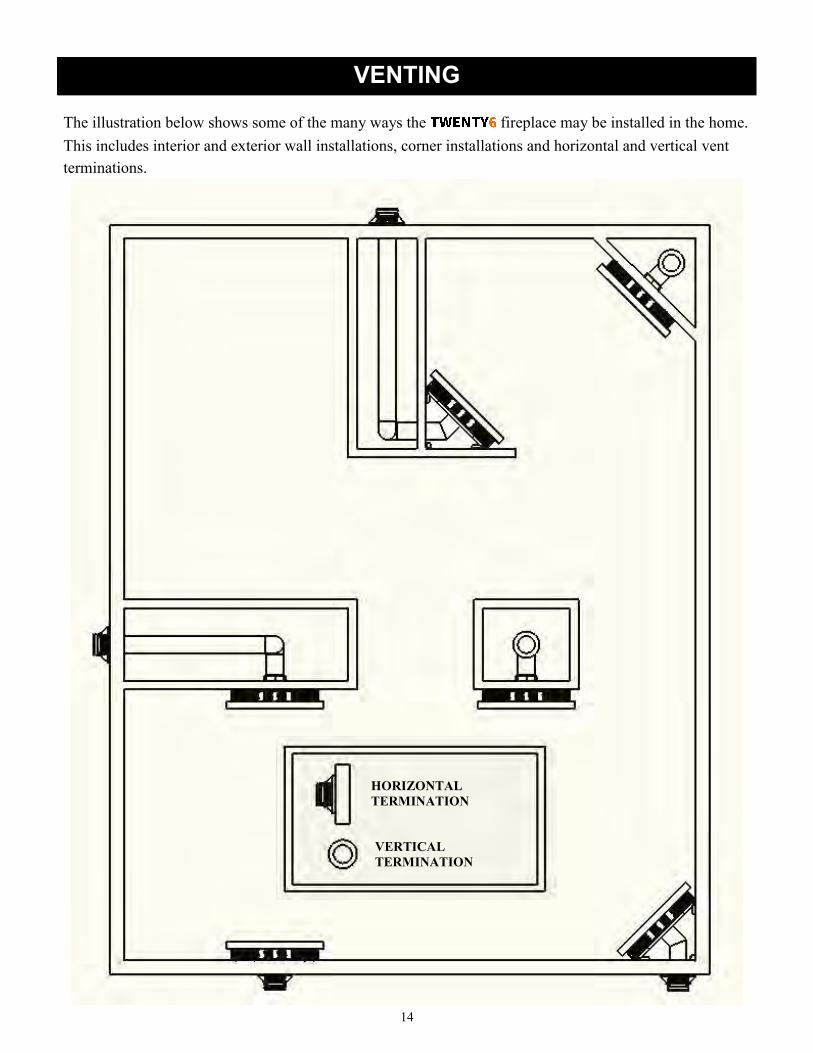
HORIZONTAL
TERMINATION
VERTICAL
TERMINATION
The illustration below shows some of the many ways the fireplace may be installed in the home.
This includes interior and exterior wall installations, corner installations and horizontal and vertical vent
terminations.

15
VENT TERMINAL CLEARANCES
Venting terminals shall not be recessed into a wall or siding.
16
ASSEMBLY & INSTALLATION
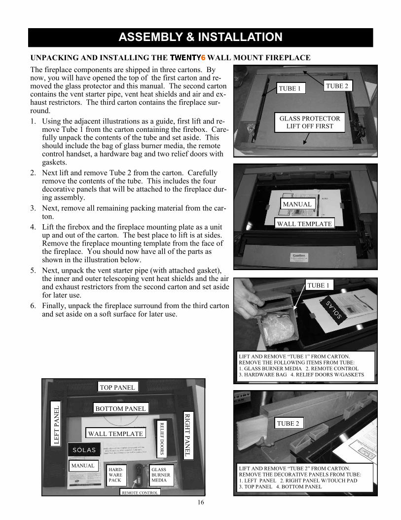
UNPACKING AND INSTALLING THE WALL MOUNT FIREPLACE
The fireplace components are shipped in three cartons. By now, you will have opened the top of the first carton and re-moved the glass protector and this manual. The second carton contains the vent starter pipe, vent heat shields and air and ex-haust restrictors. The third carton contains the fireplace sur-round.
1. Using the adjacent illustrations as a guide, first lift and re-move Tube 1 from the carton containing the firebox. Care-fully unpack the contents of the tube and set aside. This should include the bag of glass burner media, the remote control handset, a hardware bag and two relief doors with gaskets.
2. Next lift and remove Tube 2 from the carton. Carefully remove the contents of the tube. This includes the four decorative panels that will be attached to the fireplace dur-ing assembly.
3. Next, remove all remaining packing material from the car-ton.
4. Lift the firebox and the fireplace mounting plate as a unit up and out of the carton. The best place to lift is at sides. Remove the fireplace mounting template from the face of the fireplace. You should now have all of the parts as shown in the illustration below.
5. Next, unpack the vent starter pipe (with attached gasket), the inner and outer telescoping vent heat shields and the air and exhaust restrictors from the second carton and set aside for later use.
6. Finally, unpack the fireplace surround from the third carton and set aside on a soft surface for later use.
GLASS PROTECTOR
LIFT OFF FIRST
TUBE 1 TUBE 2
MANUAL
WALL TEMPLATE
TUBE 1
LIFT AND REMOVE “TUBE 1” FROM CARTON. REMOVE THE FOLLOWING ITEMS FROM TUBE:
1. GLASS BURNER MEDIA 2. REMOTE CONTROL
3. HARDWARE BAG 4. RELIEF DOORS W/GASKETS
TUBE 2
LIFT AND REMOVE “TUBE 2” FROM CARTON. REMOVE THE DECORATIVE PANELS FROM TUBE:
1. LEFT PANEL 2. RIGHT PANEL W/TOUCH PAD
3. TOP PANEL 4. BOTTOM PANEL
MANUAL
WALL TEMPLATE
TOP PANEL
BOTTOM PANEL RIG
HT
PA
NE
L
LE
FT
PA
NE
L
RE
LIE
F D
OO
RS
GLASS
BURNER
MEDIA
HARD-
WARE
PACK
REMOTE CONTROL

17
Before you begin the fireplace mounting process there are several important installation requirements that
must be met. Careful planning will make the installation easier to accomplish and will reduce the chances of
encountering problems after you start.
1. The fireplace is designed to be wall-mounted using four lag bolts to secure the fireplace mounting plate to
the wall structure. The mounts are located 16” on center and 24” on center to correspond with standard
building construction. If your home has non-standard construction or the location you have chosen for the
fireplace does not have wall studs that correspond to location of the fireplace mounts, modifications to the
wall structure will be needed. It is critical that the four lag bolts that are provided for mounting the fire-
place are firmly imbedded into the wall structure at all four locations.
2. A hole must be provided in the wall for the vent to pass through. The hole must be large enough to provide
1 1/2” clearance around the outside of the vent pipe and to allow for installation of the vent heat shields
that are provided with the fireplace. Follow the hole size requirements that are provided below exactly to
avoid problems. If the location you have chosen does not allow for 1 1/2” clearance to wooden framing in
the wall, modifications to the wall structure must made to obtain the needed vent pipe clearance.
3. All required minimum clearances to adjacent combustible materials (including side walls, ceiling and
floor) must be achieved with the position you have chosen. See the clearance information on page 6. The
listed clearances are measured from the outermost front edges of the fireplace surround and not from the
fireplace body or mounting plate. In addition the requirements for clearance to combustible materials in-
side the house, there are specific requirements and limitations that must be met for the location of the vent
terminal relative to doors, windows, corners, eaves, gas supply components and other structural elements
of the house. Please see page 15 for those specific requirements. Again, plan the installation in advance
to avoid problems.
4. The gas supply line must be located within a specific area behind the fireplace.
ASSEMBLY & INSTALLATION

18
ASSEMBLY & INSTALLATION
Once you are certain that the location you have chosen meets all the necessary mounting and safety require-
ments, you can begin the installation.
1. Tape or pin the installation template to the wall
in the position where the fireplace is to be
mounted. Note: It is important that the fire-
place is mounted in a level position. Use a
spirit level placed on the cross-hairs in the up-
per mounting holes on the template and adjust
the template position until the mounting holes
are level. Refer to the adjacent illustration.
2. Next, carefully transfer the location of the two
upper and two lower mounting holes that you
will use for your installation. Use a sharp nail,
awl or pin to pierce the template on the mount-
ing hole cross-hairs to insure an accurate trans-
fer to your wall.
3. Next transfer the location for the center of the
vent pass-through hole on the wall. Also trans-
fer at least one point on the diameter of the vent
pass-through circle. This will make it easier to scribe the circle later.
4. Finally, transfer the location of the gas supply line.
5. Remove the template and circle the transferred locations with a pencil or marker.
Vent Pass-Through (Parallel Wall Installation on an Outside Wall)
1. An unobstructed wall pass-through is required to allow for a safe installation of the fireplace vent com-
ponents. This will necessitate removal of a portion of the interior wall covering (e.g., sheetrock or plas-
ter and lath), outer wall sheathing and outer wall covering and any adjacent internal wall materials (like
insulation).
2. Scribe a 9 5/8” diameter hole around the vent pass-through center mark using a compass.
3. Use a long drill (1/8” diameter) that is held square and level to the inside wall to transfer the vent pass-
through center location from the inner wall covering through to the outer wall sheathing and outer wall
covering.
4. Carefully cut the inner wall covering along the scribed line and remove the circular wall piece. Note: It
is important to locate electrical wiring in the wall before beginning the installation process. An electri-
cian should be consulted if there is any question about wiring locations. Failure to locate and protect
wiring during the installation process my result in electrical shock or fire.
5. Remove any insulation materials from wall in the area defined by the pass-through hole.
6. Building codes in your area may require that you add blocking above and below the vent opening. The
blocking should be above and below the 9 5/8” vent opening you made in the wall and should not ob-
struct that opening. The blocking should extend to adjacent wall studs.
7. Next, mark and cut a 9 5/8” diameter hole through the outer wall covering and sheathing using the lo-
cating hole you drilled in Step 2.
8. Follow the instructions included with the vent termination (cap) to remove the appropriate amount of
outer wall covering (siding) or to install the vinyl siding shield if used. Do not install the chimney cap
at this point.
VENT PASS-THROUGH
LEVEL
24” OC
16” OC
GAS SUPPLY
CUTOUT
MOUNTING HOLES

19
ASSEMBLY & INSTALLATION
Vent Pass-Through (Parallel Wall Installation on an Interior Partition Wall)
1. An unobstructed wall pass-through is required to allow for a safe installation of the fireplace vent com-
ponents. This will necessitate removal of a portion of the interior wall covering (e.g., sheetrock or
plaster and lath), on both sides of the partition wall and any adjacent internal wall materials (like insu-
lation).
2. Scribe a 9 5/8” diameter hole around the vent pass-through center mark using a compass.
3. Use a long drill (1/8” diameter) that is held square and level to the inside wall to transfer the vent pass-
through center location from the inner wall covering through to the wall covering on the back side of
the partition wall.
4. Carefully cut the inner wall covering along the scribed line and remove the circular wall piece. Note:
It is important to locate electrical wiring in the wall before beginning the installation process. An elec-
trician should be consulted if there is any question about wiring locations. Failure to locate and protect
wiring during the installation process my result in electrical shock or fire.
5. Remove any insulation materials from wall in the area defined by the pass-through hole.
6. Building codes in your area may require that you add blocking above and below the vent opening. The
blocking should be above and below the 9 5/8” vent opening you made in the wall and should not ob-
struct that opening. The blocking should extend to adjacent wall studs.
7. Next, mark and cut a 9 5/8” diameter hole through the wall covering on the back side of the partition
wall using the locating hole you drilled in Step 2.
8. When installing the fireplace on a partition wall, the venting may be penetrating one or more interior
walls, an exterior wall, the ceiling or the roof.
9. It is important to lay out the locations of all vent pass-through’s before you begin the installation to in-
sure that the venting will line-up correctly and that the walls and ceiling meet the needed clearances to
the vent pipe.
10. The vent pass-through in the partition wall where the fireplace is mounted must be done in accordance
with the instructions for a parallel wall installation on an outside wall, following steps 1 through 6.
Vent Pipe Heat Shields
Special telescoping double heat shields for the vent pipe are provided with the
fireplace. These heat shields are a critical part of a safe installation. They are designed to
protect combustible materials in the wall immediately behind the fireplace. The only ex-
ception to this is if the corner installation kit (Part Number CK-26-1) is used. With the
corner kit, the heat shields are installed where the venting passes through the first adjacent
side wall. See the instructions included with the corner kit for specific details.

20
Gas Supply Line
1. Once the vent pass-through (or pass-through’s) are finished, the gas supply line should be installed. The
supply line should exit the wall that the fireplace will be installed on at the location specified on the in-
stallation template We suggest the installation of a shut-off valve in the supply line between the wall
and the connection to the fireplace. Your professional gas installer or local gas company will determine
the specific requirements for the gas supply line as the requirements may vary in different locations. In
every case, the installation must conform with local codes or, in the absence of local codes, with the
National Fuel Gas Code, ANSI Z223.1 or the Canadian Installation Code, CAN/CGA B149.
Installing the Fireplace Mounting Plate on the Wall
1. The fireplace mounting plate is attached to the
wall structure using four 1/4” X 1 1/2” long lag
bolts and large diameter washers that are provided
with the fireplace. It is important to use the in-
cluded hardware as the full weight of the fireplace
is supported by the mounting plate.
2. Drill a 5/32” diameter pilot hole at each of the
mounting hole locations that you marked using the
template. The pilot holes should be the full depth
of the lag bolts. Be sure that there is solid wood at
each mounting location. If not, the wall should be
reconstructed to provide the needed support.
3. Before the mounting plate can be lagged to the
wall the two tabbed sections of the telescoping
vent pipe heat shields that you set aside earlier
must be attached to the mounting plate. Each heat
shield half is held in place with three sheet metal screws (provided). The inner shield half (smaller di-
ameter) is installed from the front of the mounting plate. Slide the inner heat shield half through the
vent pipe opening in the mounting plate. Align the
three tabs with the pilot holes in the mounting
plate (as shown in the adjacent illustration) and
install the three screws.
4. The outer vent pipe heat shield half (larger diame-
ter) is installed on the rear of the mounting plate.
Slip the outer shield half over the inner shield and
align and install the three screws. See the adjacent
illustration.
5. The fireplace mounting plate is now ready to be
lagged to the wall structure.
6. With a helper pick up and align the mounting plate
over the gas supply line and line up with the four
mounting lag bolt pilot holes. These holes are in
recessed bosses. Use either the 16” or 24” on cen-
ter holes depending on the construction of the
wall.
7. Using the lag bolts and washers provided with the
fireplace, install the top lag bolts (with washers)
first, followed by the lower ones. Use a 7/16” socket wrench to tighten the lag bolts.
INNER VENT PIPE SHIELD
(Smaller Diameter)
OUTER VENT PIPE SHIELD
(Larger Diameter)
ASSEMBLY & INSTALLATION

21
Note: It may be helpful to put a light coating of dish or hand soap on the lag bolts to reduce resis-tance when tightening.
8. At this point, check to be sure that there is a 5/16” air gap between the entire flat back surface of the mounting plate and the wall surface. The gap is critical to a safe installation and if the gap is ob-structed in any way, remove the obstruction before proceeding.
9. Next check that the brackets on the mounting plate that actually hold the fireplace are level, again us-ing a spirit level. If the brackets are not perfectly level, you can adjust the right bracket by loosening the bracket fasteners and moving the bracket until it is level with the left bracket. Remember to tighten the bracket fasteners once you have achieved a level position.
10. The next step is to install the vent starter pipe onto the fireplace.
11. Remove the glass panel and glass frame assembly from the front of the firebox by loosening and re-moving the four glass frame fasteners that are lo-cated along the top edge of the glass frame.
12. While holding the glass panel and glass frame along the outer edges, tip the top of the glass frame forward a few inches.
13. Wrap your fingers around the frame and hold the glass and frame together while you lift the frame up and out of the lower glass retainer. Set the glass and frame assembly aside in a safe place.
14. Carefully place the fireplace with the front down on a protected floor.
15. At this point, it is necessary to determine whether your installation will require the addition of flow restrictors to the combustion air inlet system or the exhaust outlet or both. Refer to the venting section
that starts on page 8 to make that determination.
16. If your installation does not require any restrictors, place the vent starter pipe gasket on the back of the fireplace aligning the holes in the gasket with the pilot holes on the rear of the fireplace.
17. Align the inner pipe of the vent starter pipe with the exhaust outlet pipe on the fireplace. The vent pipe will fit tightly over the fireplace pipe. Gently push the starter pipe on to the fireplace pipe until the outer pipe flange makes contact with the starter pipe gasket. Be sure that the holes in the starter pipe flange align with the gasket and pilot holes. When the flange contacts the gasket, install the four fasteners provided with the starter pipe.
LAG BOLTS & WASHERS
LEVEL
LEVEL THE BRACKETS
INSTALLING THE
VENT STARTER
PIPE & GASKET
ASSEMBLY & INSTALLATION

22
18. If your installation does require an air restrictor or exhaust restrictor or both, these must be installed
before you install the vent starter pipe. Again, refer to the venting information starting on page 8 to
determine the specific restrictor requirements for your specific installation.
19. The exhaust restrictor is installed by placing it through the exhaust outlet pipe and resting it on the in-
ternal baffle in the firebox. It is held in place with a movable retainer clip. Simply hold the restrictor
down against the baffle and push the retainer up and tighten screw to secure the restrictor. Note: Please
take care to insure that the exhaust restrictor is centered in the exhaust outlet. Improper alignment
could adversely affect the appearance of the flames. Refer to the adjacent illustrations for placement of
the exhaust restrictor and clip.
20. If the air restrictor ring is required, first determine the number
of tabs that must be bent open. Before bending any tabs,
align the mounting holes in the ring over the four pilot holes
on the back of the fireplace. When selecting the tabs to bend,
it is important to maintain the most symmetrical pattern pos-
sible. The first tabs bent must be opposite each other and ori-
ented horizontally. If only one tab is specified, orient the ring
over the pilot holes so the split tabs are oriented horizontally
and bend up two opposing half-tabs. Additional tabs should
be evenly spaced relative to the first two. With the appropri-
ate tabs bent, re-align the mounting holes in over the pilot
holes keeping the proper orientation AND with the bent tabs
facing away from the fireplace body.
21. Place the vent starter pipe gasket on the back of the fireplace
aligning the holes in the gasket with the pilot holes on the
rear of the fireplace.
22. Align the inner pipe of the vent starter pipe with the exhaust
outlet pipe on the fireplace. The vent pipe will fit tightly over
the fireplace pipe. Gently push the starter pipe on to the fire-
place pipe until the outer pipe flange makes contact with the
vent pipe gasket. Be sure that the holes in the starter pipe
flange align with the gasket and pilot holes. When the flange
contacts the gasket, install the four fasteners provided with
the starter pipe.
ASSEMBLY & INSTALLATION
INSERTING THE EXHAUST
RESTRICTOR
INSTALLING THE RETAINER
CLIP AND SCREW
EXHAUST RESTRICTOR PROP-
ERLY INSTALLATED
STARTER PIPE
AIR RESTRICTOR
RING
GASKET
TABS FACING
AWAY FROM
FIREBOX
23
ASSEMBLY & INSTALLATION
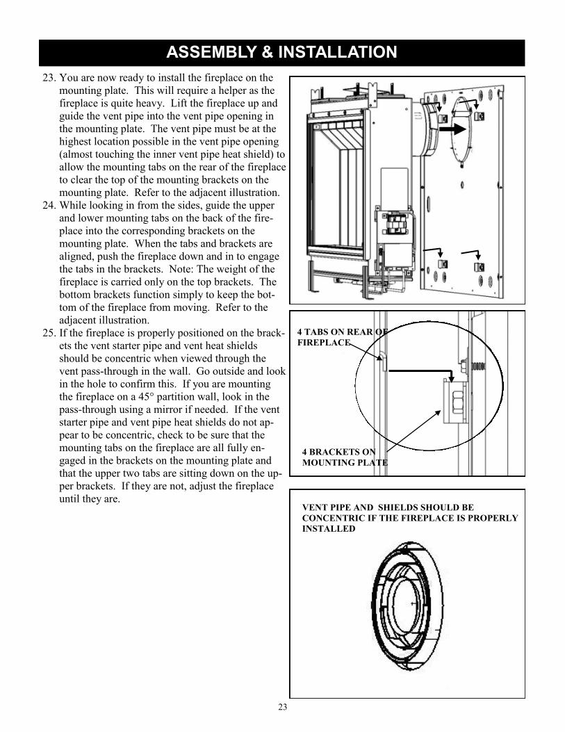
23. You are now ready to install the fireplace on the
mounting plate. This will require a helper as the
fireplace is quite heavy. Lift the fireplace up and
guide the vent pipe into the vent pipe opening in
the mounting plate. The vent pipe must be at the
highest location possible in the vent pipe opening
(almost touching the inner vent pipe heat shield) to
allow the mounting tabs on the rear of the fireplace
to clear the top of the mounting brackets on the
mounting plate. Refer to the adjacent illustration.
24. While looking in from the sides, guide the upper
and lower mounting tabs on the back of the fire-
place into the corresponding brackets on the
mounting plate. When the tabs and brackets are
aligned, push the fireplace down and in to engage
the tabs in the brackets. Note: The weight of the
fireplace is carried only on the top brackets. The
bottom brackets function simply to keep the bot-
tom of the fireplace from moving. Refer to the
adjacent illustration.
25. If the fireplace is properly positioned on the brack-
ets the vent starter pipe and vent heat shields
should be concentric when viewed through the
vent pass-through in the wall. Go outside and look
in the hole to confirm this. If you are mounting
the fireplace on a 45° partition wall, look in the
pass-through using a mirror if needed. If the vent
starter pipe and vent pipe heat shields do not ap-
pear to be concentric, check to be sure that the
mounting tabs on the fireplace are all fully en-
gaged in the brackets on the mounting plate and
that the upper two tabs are sitting down on the up-
per brackets. If they are not, adjust the fireplace
until they are.
4 TABS ON REAR OF
FIREPLACE
4 BRACKETS ON
MOUNTING PLATE
VENT PIPE AND SHIELDS SHOULD BE
CONCENTRIC IF THE FIREPLACE IS PROPERLY
INSTALLED

24
ASSEMBLY & INSTALLATION
Installing the Outer Vent Heat Shields and Vent Termination (Parallel Installation on Outside Wall)
1. Before you install the horizontal vent termination,
you must first install the second halves of the two
telescoping vent pipe heat shields. Each shield
half simply slips over the half you previously at-
tached to the fireplace mounting plate and can now
be seen inside the vent pass-through in the wall.
2. Install the outer shield first and the inner second.
Leave about 1-1/4” of the shields protruding past
the house sheathing.
3. Install the horizontal vent termination (vent cap)
by first removing the two mounting straps as they
will not be used. Be sure the arrow on the cap (if
present) is pointing up and reconfirm that all the
vent cap location requirements per page 15 and the
vent manufacturers requirements are met.
4. Slip the inner and outer vent termination pipes
onto the vent starter pipe taking care to align the
inner and outer pipes to prevent damage.
5. Slide the vent termination (cap) into the siding re-
cess (or vinyl siding shield) until it bottoms out.
Note: The rear surface of the vent termination will
push the telescoping vent pipe heat shields inward.
When the vent termination is in place the heat
shields will just touch the rear surface of the termi-
nation.
6. Pull the vent cap away from the sheathing and in-
stall a small bead of non-hardening silicone sealer
around the cap perimeter. Push the cap in place.
7. Install the mounting screws (included with the
cap) to hold the vent cap to the sheathing See the
venting manufacturers instructions for the location
of the mounting holes. Typical mounting hole lo-
cations are shown in the adjacent illustration. See
the venting manufacturers instructions for more
information or if using the vinyl siding shield.
OUTER TELE-
SCOPING SHIELD
INNER TELESCOPING
SHIELD
HORIZONTAL VENT TERMINATION
TYPICAL VENT TERMINAL MOUNTING HOLES

25
ASSEMBLY & INSTALLATION
Installing the Outer Vent Heat Shields (Partition Wall Installation)
1. Before you install the additional vent pipe and el-
bow(s) that will complete the venting installation,
you must first install the second sections of the
vent pipe heat shields to protect the combustible
materials around the vent pipe pass-through in the
partition wall that the fireplace is mounted on.
Each shield half simply slips over the half you pre-
viously attached to the fireplace mounting plate
and that can now be seen inside the vent pass-
through in the partition wall.
2. Install the outer shield first and the inner second.
Leave at least 2” of both shields protruding past
the partition wall framing or wall covering. See
the illustration on page 24.
Vent Pipe and Vent Termination Installation (Partition Wall Installation)
1. The specific details of the vent configuration from the vent starter pipe on the fireplace to the horizontal
or vertical vent termination (cap) when the fireplace is installed on an interior wall of the house will
vary depending on the location of the fireplace on the wall, what is on the back side of the wall, where
the vent termination will be located (roof or exterior wall) and on other code requirements for the loca-
tion of the vent termination as shown page 15. However, the maximum vent length, measured along the
centerline of the pipe, from the back of the fireplace to the start of the vent termination cannot exceed
30 feet, including a maximum of 20 feet of vertical rise and a maximum of 10 feet of horizontal run. If
more than two 90° elbows (or equivalent 45° elbows) are needed for your installation, the maximum
amount of horizontal run allowed is reduced. See the venting section starting on page 8 for specific in-
formation. It is important to plan the installation in advance so that you can accurately locate the any
wall or ceiling pass-through’s and the vent termination on the exterior wall or roof. The vent pipe sec-
tions are available only in certain increments of length and in adjustable length sections. Plan carefully
before you start!
2. You will find it helpful to leave access to the area behind the partition wall to facilitate installation of
the vent components. The pipe sections may have twist lock connections which will be difficult to exe-
cute without good access.
3. Be sure that the two vent pipe heat shields extend at least 2” beyond the rear side of the partition wall
adjacent to the fireplace after the venting is installed.
4. Maintain a minimum 1 1/2” unobstructed air space around the vent pipe where it passes through other
interior walls, the ceiling, the exterior wall or the roof.
5. Note: Vent manufacturer’s instructions and some building codes may require the addition of blocking
above and below all wall pass-through’s, the addition of vent manufacturer supplied fire-stops, wall
thimbles, attic insulation shields, interior trim collars, vent support brackets, or other components.
Please check with the authority having jurisdiction in your area when planning the venting installation
to determine the specific code requirements and exact venting components that are required for your
installation.
OUTER TELE-
SCOPING SHIELD
INNER TELESCOPING
SHIELD
BACK OF PARTITION WALL

26
Gas Connection.
1. Verify that the gas type is correct for the fireplace by looking
at the rating plate that is attached to the right side of the fire-
place, adjacent to the control battery pack. Note: The fire-
place is shipped from the factory equipped to burn the fuel
listed on the rating plate. Fuel conversion in the field is not
allowed.
2. The gas connection should now be made from the gas supply
line to the inlet regulator on the fireplace. Use only a quali-
fied gas installer to make the connection.
3. The fireplace is shipped from the factory with a 3/8” tube
OD (male) connection.
4. The gas supply piping should have a separate gas shut-off
valve and a 1/8” NPT plugged tapping upstream of the valve.
We recommend installing a shut-off valve between the gas
supply line where it penetrates the wall / fireplace mounting plate and the inlet to the regulator on the
fireplace. This will allow gas to be shut-off to the fireplace by simply removing the fireplace surround
to gain access to the shut-off valve.
5. The fireplace and its inlet regulator and main burner valve must be disconnected from the gas supply
piping system during any pressure testing of that system at test pressures in excess of 1/2 psi (3.5kPa).
6. The fireplace must be isolated from the gas supply piping system by closing the gas shut-off valve dur-
ing any pressure testing of the gas supply system at test pressures equal to or less than 1/2 psi (3.5kPa).
After the gas supply has been connected, use a commercial gas leak detector or apply a soapy water so-
lution to all the fittings to check for gas leaks. Never use a flame to test for leaks.
ASSEMBLY & INSTALLATION
CONNECT GAS SUP-
PLY LINE TO 3/8”
TUBE OD (MALE)
RECOMMENDED LO-
CATION FOR A SHUT-
OFF VALVE

27
ASSEMBLY & INSTALLATION
Installing or Replacing the Batteries
1. The valve control module is powered by four “AA”
batteries. The batteries are mounted within the Valve
Receiver Module located on the right side of the fire-
place attached to a drop-down mounting bracket for
easy accessibility. Refer to the adjacent illustration.
2. Loosen the thumb screw on the module drop-down
mounting bracket by turning counter-clockwise until
the threads are fully disengaged from the base
bracket.
3. Rotate the Valve Receiver Module and mounting
bracket. Toward you 90 degrees.
4. Slide off the Battery compartment cover.
5. Install the 4 “AA” batteries, supplied, using the
guides inside the battery pack to show you the correct
battery orientation.
6. Replace the battery compartment cover. Rotate the
Valve Receiver Module and mounting bracket into its
home position and tighten the thumb screw to secure.
7. The remote handset is powered by three “AAA” bat-
teries. The access panel is located on the back of the
handset and simply snaps open to provide access to
the battery compartment. Install the three batteries as
shown on the label inside the remote control battery
compartment.
8. Replace the remote handset access panel.
Placing the Burner Glass Media
The burner glass media poly-bag that you set aside
when you unpacked the fireplace contains the correct
amount of glass material to cover the burner. The en-
tire contents of the bag should be evenly distributed
over the burner tray.
1. Locate the burner in the fireplace. Refer to the ad-
jacent illustration.
2. Carefully clip one corner of the poly-bag to form a
pouring spout. The opening should be large
enough to allow the glass media to flow but not so
large that you can’t control the flow.
3. You will notice that the burner surface is designed
with turned-up edges that form a tray to hold the
glass media.
BURNER TRAY
ROTATE THUMB
SCREW

28
ASSEMBLY & INSTALLATION
4. Starting at one end, pour the glass media onto the
burner tray, keeping the pouring spout on the poly-
bag toward the center of the burner to avoid spillage
of glass pieces over the sides of the burner. See the
adjacent illustrations.
5. Once you have poured all of the glass burner media
into the burner tray, carefully smooth the glass pieces
out so they have a uniform depth over the entire sur-
face of the burner. When the burner glass media is
properly placed, it should look like the adjacent illus-
trations.
6. Note: If a few pieces of glass escape over the edges
of the burner tray during installation, it is not a prob-
lem. They will simply land in the area below the
burner and will do no harm.
Relief Door Installation
1. The two relief doors are shipped separated from the
fireplace and must be installed on the top of the fire-
box at this point in the installation. Note: The relief
doors include a gasket material that covers the full
bottom surface. Use care in handling the relief doors
to avoid damage to the gasket material.
2. The first illustration below shows one of the two sets
of relief openings and relief door retainers.
3. The relief doors include line-up tabs that correspond to slotted retainers on the firebox.
4. Tip each relief door enough to allow the rear line-up tab to engage the rear retainer slot. Refer to the
second illustration below.
5. Rotate the front edge of each relief door so they line-up over front retainers.
6. Gently spring the front forward so it will allow the relief door front line-up tab to engage on the re-
tainer. Refer to the first illustration on the top of page 29.
7. The relief doors should be able to move up and down freely on the retainers if properly installed.
8. When the relief door installation is complete, the doors should be in the full down position. Refer to the
second illustration on the top of page 29.
BURNER GLASS MEDIA
PARTIALLY INSTALLED
BURNER GLASS MEDIA
FULLY INSTALLED
RELIEF OPENINGS
RETAINERS
RELIEF DOOR FRONT TAB
RELIEF DOOR REAR TAB ENGAGED IN
REAR RETAINER

29
Installing the Front Glass Panel and Frame
After burner media and relief doors been installed, the next step is to replace
the front glass panel and frame.
1. Carefully pick up the glass and glass frame assembly by grasping the sides
of the frame and using your thumbs and fingers to hold the glass in place
within the gasket and frame.
2. With the glass frame (and glass) held at a slight angle (leaving room for
your fingers between the frame and the firebox) insert the bottom edge of
the frame into the frame retainer located on the bottom front of the firebox.
Take care to center the frame from left to right.
3. Once the bottom edge is in place, move your fingers out of the way and
press the top of the frame against the firebox while pushing down to be
sure the frame is fully engaged in the frame retainer.
4. Hold the frame in place with one hand and insert the four glass frame fas-
teners along the top edge of the glass frame. Tighten the fasteners until
they are hand-tight.
5. Tighten each fastener 1/2 turn at a time, working from one side to the
other, until the glass frame has made contact with the firebox face along
the entire top edge. Do not over-tighten the fasteners as this can put exces-
sive stress on the glass.
ASSEMBLY & INSTALLATION
RELIEF DOOR FRONT TAB
ENGAGED ON RETAINER
RELIEF DOOR SHOWN IN
PROPER OPERATING POSITION

30
ASSEMBLY & INSTALLATION
Installing the Outer Panels
1. The four outer decorative panels are secured to the fire-
place with philips head screws. The top and bottom pan-
els are secured to the fireplace mounting plate with sheet
metal screws. All other screws are philips head machine
screws.
2. Install the top panel first. Align the three holes along the
rear edge of the panel with pilot holes along the top edge
of the fireplace mounting plate.
3. Insert and tighten the three sheet metal screws. A mag-
netic nut driver is helpful.
4. Install the left side panel next. Align the three holes
along the rear edge of the panel with the PEM nuts along
the edge of the fireplace mounting plate. Insert the three
philips head screws but do not fully tighten.
5. Locate the fastener hole at the top front edge of the left
side panel and align with the PEM nut in the front of the
top panel. Insert the philips head screw.
6. Make sure the edges of the panel are aligned with the
edges of the top panel and mounting plate and tighten all
four philips head screws.
7. Position the right side panel so it aligns with the three
PEM nuts on the mounting plate and the front PEM
nut on the top panel. Align the rear and top panel
edges with the adjoining parts and insert and tighten
the four philips head screws.
8. Install the bottom panel next. Guide the rear flange on the
panel upward until the mounting holes in the flange line
up with the pilot holes in the mounting plate.
9. Attach the panel to the mounting plate using sheet metal screws along the back edge of the panel. Note: It
may make installation of the sheet metal screws easier if you remove the two lower surround mounting
brackets from the front of the fireplace. A magnetic nut-driver will also be helpful.
10. Attach the bottom panel to the side panels by aligning the fastener holes in the bottom panel with the PEM
nuts in the front corners of the bottom flanges on the side panels. Insert and tighten the two philips head
screws.
11. Reinstall the lower surround brackets if you removed them by inserting and tightening the two sheet metal
screws in each bracket.
LOWER SURROUND BRACKETS

31
ASSEMBLY Installing the Fireplace Surround The decorative surround for the fireplace is held in place by four brackets. Two are located on the top of
the fireplace and two on the bottom. There are mating brackets and catch plates on the surround itself. Re-
fer to the adjacent illustrations when installing the surround.
1. Unpack the surround from shipping box.
2. With a helper, lift the surround up and identify the
top by looking for the vertical brackets that are visi-
ble from the rear of the surround.
3. Move the surround into place, generally centering the
surround opening over the glass panel. Keep the bot-
tom of the surround tipped slightly away from the
fireplace.
4. While looking behind the surround, guide the two
surround brackets onto the forward detent of the mat-
ing brackets on the fireplace top. You might find it
easier to engage one bracket and then the other.
Lower the surround until both bracket sets are fully
mated.
5. Carefully push the top of the surround so that the sur-
round brackets slide into the rear detent of the mating
brackets on the fireplace top.
6. Carefully swing the bottom of the surround toward the base of the fireplace until the catch plates on the
bottom flange of the surround are aligned with the spring loaded plungers on the bottom flanges of the
lower surround mounting brackets.
7. To remove the surround, pull the bottom edge of the surround outward to disengage the spring loaded
plungers and then lift the top up and off the upper brackets.
8. To prevent damage to the surround, always set the surround in a safe place while it is removed from the
fireplace.
UPPER SURROUND BRACKETS WHEN
PROPERLY MATED
CATCH
PLATE
PLUNGER

32
LIGHTING AND OPERATION
1. STOP! Read the safety information above on this label.
2. This appliance is equipped with an ignition device that automatically lights the pilot. Do not try to light the pilot by hand.
3. Using the Remote Handset, or the optional Wall Switch, push the “OFF” button until you hear an audible signal to insure
the appliance is Off.
4. Wait five (5) minutes to clear out any gas. Then smell for gas including near the floor. If you smell gas, STOP! Follow “B”
in the safety information above. If you don’t smell gas, proceed to step 5.
5. Using either the Remote Handset, or the optional Wall Switch, simultaneously press the “ON” and “High Flame” but-
tons. An audible signal confirms the start sequence has begun.
6. Continuing beeps confirm the ignition is in process. Once lighting the pilot flame should appear as shown in Fig.2. Once the
pilot is confirmed, the main burner ignites on high.
NOTE: If the pilot does not stay lit after several tries, proceed to step 9.
7. Use the flame height adjustment buttons on either the Remote Handset or the optional Wall Switch to adjust the flame. Press
the button twice to decrease the flame height to its lowest setting, press the button twice to increase flame height to the
highest setting. Pressing the or button once will module the flame to intermediate settings. The Remote Handset can
also be used to control the appliance thermostatically.
8. Press and hold the button on the Remote Handset or optional Wall Switch to set the appliance to Pilot flame only.
9. If the appliance will not operate, follow the instructions “TO TURN OFF GAS TO THE APPLIANCE” and call your gas ser-
vice technician or gas supplier.
WARNING: If you do not follow these instructions exactly, a fire or explosion may result causing property damage, personal injury or loss of life.
When lighting this appliance, follow these instructions exactly.
A. This appliance is equipped with an ignition device that automatically lights the pilot. Do not try to light the pilot by hand.
B. BEFORE OPERATIONG THE BURNER SYSTEM, smell around the appliance area for gas. Be sure to smell next to the
floor because some gas is heavier than air and will settle on the floor.
WHAT TO DO IF YOU SMELL GAS
Do not try to light the appliance.
Do not touch any electric switch; do not use any telephone in your building.
Immediately call your gas supplier from a neighbor’s telephone. Follow the gas supplier’s instructions
If you cannot reach your gas supplier, call the fire department.
C. Use only your hand to operate the gas controls. Never use tools. If a knob will not push in or turn by hand, don’t try to re-
pair it, call a qualified service technician. Force or attempted repair may result in a fire or explosion.
D. Do not use this appliance if any part has been under water. Immediately call a qualified service technician to inspect the
appliance and to replace any part of the control system which has been under water.
OPERATING INSTRUCTIONS
TO TURN OFF GAS TO THE APPLIANCE
FIG. 2
High Flame
Low Flame ON/OFF
FIG. 1
1. To turn off gas to the appliance,
push and release the “OFF”
button on either the Remote Hand-
set or on the optional Wall Switch.
You will hear an audible signal
confirming the off setting.
2. TO TURN OFF THE GAS SUP-
PLY TO THE APPLIANCE, close
the shut-off valve on the gas sup-
ply line to the appliance.
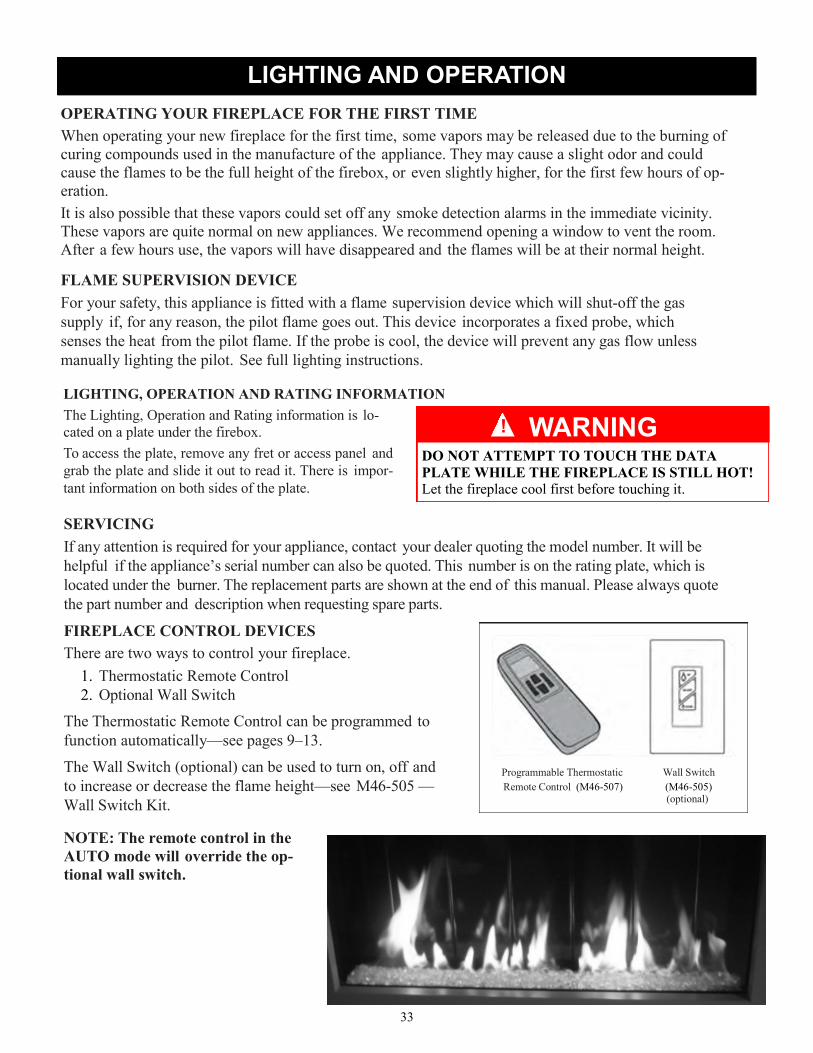
33
WARNING
LIGHTING AND OPERATION
OPERATING YOUR FIREPLACE FOR THE FIRST TIME
When operating your new fireplace for the first time, some vapors may be released due to the burning of
curing compounds used in the manufacture of the appliance. They may cause a slight odor and could
cause the flames to be the full height of the firebox, or even slightly higher, for the first few hours of op-
eration.
It is also possible that these vapors could set off any smoke detection alarms in the immediate vicinity.
These vapors are quite normal on new appliances. We recommend opening a window to vent the room.
After a few hours use, the vapors will have disappeared and the flames will be at their normal height.
FLAME SUPERVISION DEVICE
For your safety, this appliance is fitted with a flame supervision device which will shut-off the gas
supply if, for any reason, the pilot flame goes out. This device incorporates a fixed probe, which
senses the heat from the pilot flame. If the probe is cool, the device will prevent any gas flow unless
manually lighting the pilot. See full lighting instructions.
!
Programmable Thermostatic Wall Switch
Remote Control (M46-507) (M46-505) (optional)
LIGHTING, OPERATION AND RATING INFORMATION
The Lighting, Operation and Rating information is lo-
cated on a plate under the firebox.
To access the plate, remove any fret or access panel and
grab the plate and slide it out to read it. There is impor-
tant information on both sides of the plate.
SERVICING
If any attention is required for your appliance, contact your dealer quoting the model number. It will be
helpful if the appliance’s serial number can also be quoted. This number is on the rating plate, which is
located under the burner. The replacement parts are shown at the end of this manual. Please always quote
the part number and description when requesting spare parts.
FIREPLACE CONTROL DEVICES
There are two ways to control your fireplace.
1. Thermostatic Remote Control
2. Optional Wall Switch
The Thermostatic Remote Control can be programmed to
function automatically—see pages 9–13.
The Wall Switch (optional) can be used to turn on, off and
to increase or decrease the flame height—see M46-505 —
Wall Switch Kit.
DO NOT ATTEMPT TO TOUCH THE DATA
PLATE WHILE THE FIREPLACE IS STILL HOT!
Let the fireplace cool first before touching it.
NOTE: The remote control in the
AUTO mode will override the op-
tional wall switch.

34
MAXITROL GV60 CONTROL SYSTEM
HOW TO TURN YOUR FIREPLACE OFF (including pilot)
Familiarize yourself with each of these methods before operating your fireplace.
Handset and Wall Switch: Press and hold the OFF button for a second (either on the handset or the wall
switch).
If the flames are on, they go down and you hear the valve motor wind down. You hear a clunk and a beep
indicating that the valve has received the signal from the remote control.
How to Ensure Your Fireplace Cannot Be Turned ON Inadvertently
You can use the following method to ensure that your fireplace will not turn on when you don’t want it on.
First, ensure your fireplace is turned off—including the pilot—and cold BEFORE going ahead.
Close the shut-off valve on the gas supply line to the appliance.
Remove all batteries from the receiver as well as the battery from the handset.
Automatic Shut-Off (in certain conditions) Your fireplace’s remote control is equipped with an automatic shut-off mechanism which is activated in
certain conditions. See page 13 in the Remote Control Operation section for a description of this feature.
NOTE: Before using the remote control system for the first time, the receiver and the handset are syn-
chronized at the factory. See the section Remote Control Initial Set-up on page 39 of this manual if the
receiver and handset lose synchronization.
IMPORTANT: BEFORE YOU BEGIN, please note that on this system, the settings of time, temperature
and automatic ON/OFF can only be programmed when the function display is flashing. Be patient
when programming as it can take a few seconds to set.
Wall Switch
( optional) Programmable Thermostatic Remote Control

35
MAXITROL GV60 CONTROL SYSTEM
Current temperature
(F or C)
Period start or end
(Temp, Timer) Battery status
Display Overview
Note: In the TEMP or TIMER modes, the remote
handset senses the room temperature and adjusts the
flame accordingly.
To communicate, the handset should be within 15
feet (4.5 meters) of the fireplace.
Set (scrolls through
modes and settings)
OFF (returns to set
mode, turns the burner and the
pilot off)
Large flame button (flames up, sets hours, temperature)
Small flame button (flames down and off, sets minutes, temperature)
Handset
sensor
Current
programmed
period (Timer)
Current time
(12 or 24 hour
clock)
Modes (Manual,
Temperature, Timer) MANTEMPTIMER
Do not leave the handset on the hearth, mantel, or
on top of the fireplace. Handset Overview
TO TURN ON APPLIANCE TO TURN OFF APPLIANCE
When pilot ignition is confirmed, motor turns auto-
matically to maximum flame height.
CAUTION
On the valve, turn MAN knob on the ON, full
counterclockwise position.
Simultaneously press the OFF
and (large flame) buttons
until a short beep confirms the
start sequence has begun; re-
lease buttons.
Continuing beeps confirm the
ignition is in process.
Once pilot ignition is con-
firmed, there is main gas
flow.
After main burner ignition
the handset will automati-
cally go into manual (MAN)
control mode.
In standby mode: Press and
hold (large flame) button
to increase flame height.
Press OFF button.
When the pilot is off, it will take
2 minutes before it can be lit
again.
STANDBY MODE (Pilot Flame)
Press and hold (small flame) to set appliance at
pilot flame
FLAME HEIGHT ADJUSTMENT

36
TIMER
TEMP
MAN
MAXITROL GV60 CONTROL SYSTEM
Press and hold (small
flame) button to decrease
flame height or to set the ap-
pliance at pilot flame.
For fine adjustment tap the (large flame) or (small flame) buttons.
MODES OF OPERATION
Express Low and High Fire
Double-click (small flame)
button. “LO” will be displayed.
NOTE: Flame goes to high fire
first before going to designated
low fire.
Double-click (large flame)
button. Flame automatically
goes to high fire. “HI” will be
displayed. x 2
x 2
SETTING °C/24-HOUR OR °F/12-HOUR
In MAN mode, press OFF
and (small flame) buttons
until display changes from
Farenheit/12-hour clock to
Celsius/24-hour clock and
vice versa.
SETTING THE TIME
Briefly pressing the SET button
changes the mode of operation in
the following order:
and back to
MAXITROL GV60 CONTROL SYSTEM MAN
MAN
TIMER MAN
TEMP TEMP
NOTE: Manual mode can also be reached by
pressing either the (large flame) or the
(small flame) buttons.
- Manual Mode - Manual
Flame Height Adjustment.
- Daytime Tempera-
ture Mode (Appliance must be in
standby mode; pilot ignited) - The
room temperature is measured and
compared to the set temperature.
The flame height is then automati-
cally adjusted to achieve the Day-
time Set Temperature.
TEMP
TEMP
- Timer Mode (Appliance
must be in standby mode; pilot ignited) -
The timers P1 and P2 (Program 1, Pro-
gram 2) each can be programmed to go
ON and OFF at specific times. For in-
structions see Timer Programming Mode.
NOTE: The display shows the set temperature every 30
seconds.
The time display will flash af-
ter either:
» Installing the battery or
» Simultaneously pressing the
(large flame) and
(small flame) buttons
Press (large flame) button
to set the hour.
Press (small flame) button to set the minute.
Press OFF or simply wait to return to MAN
mode.
- Daytime Tempera-
ture Mode (Appliance must be in
standby mode; pilot ignited) - The
room temperature is measured and
compared to the set temperature.
The flame height is then automati-
cally adjusted to achieve the Day-
time Set Temperature.

37
TEMP
Briefly press SET button to
scroll to TEMP
(sun) mode. Hold the SET but-
ton until the TEMP flashes.
TEMP
MAXITROL GV60 CONTROL SYSTEM
SETTING THE ON / OFF TEMPERATURES
SETTING THE “DAYTIME” TEMPERATURE
Default Settings: (sun), 23°C / 74°F TEMP
Press (large flame) but-
ton to increase the Daytime
Set Temperature.
Press (small flame) but-
ton to decrease Daytime
Set Temperature.
Press OFF or simply
wait to complete pro-
gramming.
SETTING THE “NIGHTTIME SETBACK”
TEMPERATURE
Default Settings: (moon), “- -” (OFF) TEMP
Briefly press SET button to
scroll to TEMP
(moon) mode. Hold the SET
button until the TEMP flashes.
Press (large flame) but-
ton to increase Nighttime
Setback Temperature.
Press (small flame) button
to decrease Nighttime
Setback Temperature.
Press OFF or simply wait to
complete programming.
Tip
Set the different parameters when they are flashing.

38
MAXITROL GV60 CONTROL SYSTEM
SETTING PROGRAM TIMERS
You can program two periods of time between
12:00 am and 11:50 pm in each 24-hour cycle.
The Programs P1 and P2 must be set in the fol-
lowing order during a 24-hour cycle: P1 ,
P1 , P2 and P2 .
The icon indicates the beginning of the pe-
riod (ON) and the icon indicates the end of
the period (OFF).
If P1 = P1 , P2 = P2 the program-
ming is cancelled.
To keep the fireplace ON all night, set P2 at
11:50 am and P1 at 12:00 am.
Default settings:
Program 1: P1 6:00 am P1 8:00 am
Program 2: P2 11:50 pm P2 11:50 pm
Briefly press SET button to
scroll to TIMER mode.
SETTING P1 ON TIME
Hold the SET button until
P1 (sun) is displayed
and the time flashes.
Press (large flame) button
to set the hour.
Press (small flame) button
to set the minutes.
SETTING P1 OFF TIME
Briefly press SET button o scroll
to TIMER P1 (moon) while
the time flashes.
Press (large flame) button to
set the hour.
Press (small flame) button to
set the minutes.
SETTING P2 ON TIME
Briefly press SET to scroll to TIMER mode
P2 (sun) while the time flashes.
Follow the instructions given to set P1 ON
time.
SETTING P2 OFF TIME
Briefly press SET to scroll to TIMER mode
P2 (moon) while the time flashes.
Follow the instructions given to set P1 OFF
time.
Press OFF button to save these settings. The tim-
ers are programmed. See the diagram on pro-
gramming sequences on the following page.
Tip
If you want to program only one period, program P1
and P1 with desired times and program P2 and
P2 with the same time as P1 .

39
☼ ☼ ☼
Set Temp 74°F Set Temp 40°F Set Temp 74°F Set Temp 40°F
Timer Programming Example (default temperatures shown)
6:00 a.m.—P1
Start time
☼ ☼
8:00 a.m.—P1
End time
4:00 p.m.—P2
Start time
10:00 p.m.—P2
End time
6:00 a.m.—P1
Start time
No communication. If there is no communication between the receiver and the handset for a
period of 6 hours, the appliance goes into pilot mode.
No change in flame height. If there is no change in flame height for a period of 6 hours, the ap-
pliance goes into pilot mode.
NOTE: In TEMP or TIMER modes, the flame height will vary according to room temperature.
The appliance will continue to work normally. However, if the room temperature remains the same
for 6 hours, the appliance will go into pilot mode.
Low batteries in the receiver. With low battery power in the receiver the system shuts off com-
pletely.
NOTE: This does not apply when the power supply is interrupted.
No change in pilot. The appliance shuts off completely when it is continually in pilot position—
without any change—for a period of 5 days.
AUTOMATIC TURN DOWN
AUTOMATIC SHUT OFF
LOW BATTERY INDICATION
DO NOT USE a screwdriver or other metallic ob-
ject to remove the batteries from the battery box or
the handset! This could cause a short circuit.
CAUTION
Remote handset: The battery icon will show when the battery needs to be replaced.
Replace with one 3 “AAA” alkaline batteries.
Receiver: Three short ‘beeps’ will sound when the motor turns when the batteries need to be re-
placed. Replace with four 1.5 V alkaline batteries.
HANDSET / RECEIVER MATCH
The remote control handset and receiver are program- med to function together. In case of a re-
placement of the handset or the receiver, you will need to reset the receiver to allow them to func-
tion together. Contact your dealer for details.
MAXITROL GV60 CONTROL SYSTEM

40
A qualified service agency should conduct an annual inspection and maintenance of your includ-
ing the overall installation and venting to keep it running safely. The following procedures should be per-
formed only by a qualified service person. The gas supply should be turned off and the stove should be
completely cool whenever a maintenance procedure is performed. All parts of the appliance that are removed for
servicing must be replaced prior to operation.
WARNING: Do not operate the appliance with the glass front removed, cracked or broken.
Replacement of the glass should be done by a qualified service person.
WARNING: Use only glass assembly, P/N 26-510 which includes the glass panel, frame and gasket.
Do not use substitute materials. Do not strike or slam the glass front. The appliance area must be
kept clear and free from combustible materials, gasoline and other flammable vapors and liquids.
REPLACING THE GLASS
The glass mounting system consists of the glass panel, special glass gasket and the metal glass frame.
Should the glass need to be replaced, you must replace the entire glass/glass frame assembly (PN 26-510).
See page 46 for information on obtaining replacement parts. Use the following procedure and refer to the
illustrations on page 29 of this manual.
1. Turn the fireplace completely off and allow it to cool to room temperature.
2. Remove the fireplace surround. See instructions on page 31.
3. If the glass is broken, be sure to wear gloves and eye protection.
4. Remove the glass frame fasteners from the top edge of the glass frame.
5. This will allow the glass frame to tip slightly forward. The glass may be loose in the frame, so it is very
important to support both the glass and the frame when handling. Place your thumbs on the outside of
the glass frame and wrap your fingers around the frame and onto the glass. Squeeze the frame and glass
while moving. Carefully lift the glass frame and glass up and off the fireplace. Set the glass and frame
aside on a padded surface. If the glass is broken, do this over spread out newspaper to catch all loose
material. Wrap the old glass frame, glass and gasket in several layers of newspaper and discard.
Installing the replacement glass/glass frame assembly.
1. Unpack the new glass/glass frame assembly taking care when handling.
2. Carefully pick up the glass and glass frame assembly by grasping the sides of the frame and using your
thumbs and fingers to hold the glass in place within the gasket and frame.
3. With the glass frame (and glass) at a slight angle (leaving room for your fingers between the frame and
the firebox) insert the bottom edge of the frame into the frame retainer located on the bottom front of
the firebox. Take care to center the frame from left to right. Once the bottom edge is in place, move
your fingers out of the way and press the top of the frame against the firebox while pushing down to be
sure the frame is fully engaged in the frame retainer. Hold the frame in place with one hand and rein-
stall the glass frame fasteners, leaving them loose.
4. Tighten the glass frame fasteners in stages working from the center out. Continue the process until all
fasteners are uniformly tight. Do not over-tighten the fasteners.
5. Replace the fireplace surround.. See instructions on page 31.
CLEANING THE GLASS
WARNING: Never clean the glass while it is hot. Do not use abrasive cleaners or cleaners containing
ammonia.
NOTE: A micro-fiber cleaning cloth and plain water is recommended by the glass manufacturer.
MAINTENANCE

41
MAINTENANCE
Inspecting the Venting
An inspection of both the inner and outer vent pipes and the vent terminal should be made as part of the an-nual service appointment. The venting must have no blockage and be in good repair. The vent manufac-turer’s instructions may provide specific details on vent inspection. Any vent sections that are disassem-bled must be reassembled and sealed as required.
This appliance should be inspected before use and at least annually by a qualified service person.
More frequent cleaning may be required due to excessive dust or lint from carpeting, bedding mate-
rials, pets, etc. It is imperative that control compartments and circulating air passageways of this
appliance be kept clean.
Cleaning the Burner and Firebox During the annual inspection and maintenance appointment, the service person should clean the burner and firebox. To gain access to the firebox and burner, follow the instructions beginning on page 34 of this man-ual. DO NOT USE A VACUUM CLEANER TO CLEAN THE GLASS BURNER MEDIA. A vacuum cleaner may be used to clean the metal parts of the firebox. Leave the glass burner media in place. Use a soft brush to clean the burner glass media. If the burner media does need to be removed, care-fully scoop it off the burner and avoid dropping glass pieces in the air gaps around the burner. Follow the instructions on page 27 of this manual when replacing the burner media on the burner top.
Air Flow
The utilizes a convection air heat exchange system to maximize heat delivered from the fire-
place. It is important that air flows freely through the convection air system and out the top and side air
grills. Do not place objects under the fireplace that will block the convection air inlet flow or in front of

42
Date of Service ____________________
Serviced By ____________________ __
Service Performed
Inspect Venting
Clean Burner & Firebox
Clean Control Area
Clean Convection Air System
Leak Test Gas Connections
Other __________________________
Date of Service ____________________
Serviced By ____________________ __
Service Performed
Inspect Venting
Clean Burner & Firebox
Clean Control Area
Clean Convection Air System
Leak Test Gas Connections
Other __________________________
Date of Service ____________________
Serviced By ____________________ __
Service Performed
Inspect Venting
Clean Burner & Firebox
Clean Control Area
Clean Convection Air System
Leak Test Gas Connections
Other __________________________
Date of Service ____________________
Serviced By ____________________ __
Service Performed
Inspect Venting
Clean Burner & Firebox
Clean Control Area
Clean Convection Air System
Leak Test Gas Connections
Other __________________________
MAINTENANCE LOG
Date of Service ____________________
Serviced By ____________________ __
Service Performed
Inspect Venting
Clean Burner & Firebox
Clean Control Area
Clean Convection Air System
Leak Test Gas Connections
Other __________________________
Date of Service ____________________
Serviced By ____________________ __
Service Performed
Inspect Venting
Clean Burner & Firebox
Clean Control Area
Clean Convection Air System
Leak Test Gas Connections
Other __________________________
We strongly recommend that you keep a log of the regular maintenance that is performed on your
fireplace. We have provided the forms below to make it easy. Simply ask your qualified service per-
son to fill out one of the maintenance record forms below, each time the fireplace is serviced. This
will help insure that all of the required maintenance procedures have been completed, at least annu-
ally. Regular maintenance will help keep the fireplace functioning in a safe and reliable manner.
Additional forms are available from your installer or service person when needed.

43
REPLACEMENT PARTS LIST
*This is a quick response thermocouple. Replace it only with SÓLAS Part Number M26-502.
PART NAME P/N PART NAME P/N
Pilot Head NG/LP 26-501 Burner Orifice (NG) 26N-509
Pilot Thermocouple* M26-502* Burner Orifice (LP) 26P-509
Pilot Injector (NG) 26N-503 Burner Glass Media – Clear 26-511
Pilot Injector (LP) 26P-503 Burner Module (NG) 26N-901
Receiver Module (Maxitrol) M46-504 Burner Module (LP) 26P-901
Wall Switch Panel (optional) M46-505 Firebox Panel – Rear 26-512
Remote Handset (Maxitrol) M46-507 Firebox Panel – Left 26-513
Gas Valve (Maxitrol) M46-515 Firebox Panel – Right 26-514
TC Line Red M46-701 Thermocouple Interrupter Block M46-703
TC Line Yellow M46-702 8-Wire Connecting Cable M46-704
Glass Assy (including gasket & frame) 26-510
For replacement parts and customer service, contact your dealer or:
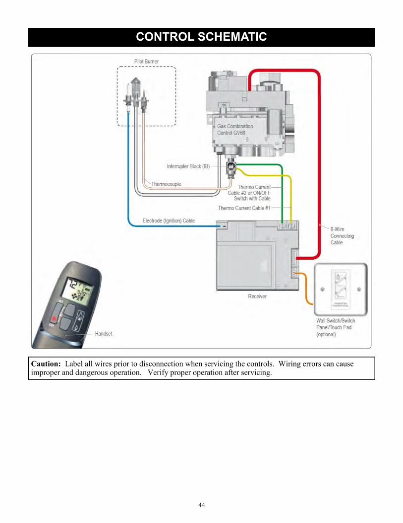
44
CONTROL SCHEMATIC
Caution: Label all wires prior to disconnection when servicing the controls. Wiring errors can cause improper and dangerous operation. Verify proper operation after servicing.

45
INSTALLATION RECORD
The installer should complete the form below that describes the details of the installation. Having this writ-
ten record of installation information available will greatly expedite trouble-shooting should any problem
arise with your stove. The installer should keep a duplicate of this form for their records.

47

48
V13 / 8-15-14
Model #: ________________________________ Serial #: _________________________________
Date Purchased: __________________________ Date Installed: ____________________________
Manufactured by:
Progressive Manufacturing Inc.
4 Technology Drive, Suite 5
West Lebanon, NH 03784
USA