INSTALLATION/OPERATING/ MAINTENANCE ... may result in reduced efficiency of the unit or a total...
24
INSTALLATION/OPERATING/ MAINTENANCE INSTRUCTIONS Air to Water Heat Pump LSQ03RC,04RC,05RC,06RC, 10RC
Transcript of INSTALLATION/OPERATING/ MAINTENANCE ... may result in reduced efficiency of the unit or a total...
INSTALLATION/OPERATING/ MAINTENANCE
INSTRUCTIONS Air to Water Heat Pump
LSQ03RC,04RC,05RC,06RC, 10RC
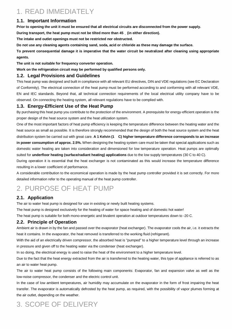
1. READ IMMEDIATELY 1.1. Important Information Prior to opening the unit it must be ensured that all electrical circuits are disconnected from the power supply.
During transport, the heat pump must not be tilted more than 45 (in either direction). The intake and outlet openings must not be restricted nor obstructed. Do not use any cleaning agents containing sand, soda, acid or chloride as these may damage the surface. To prevent consequential damage it is imperative that the water circuit be neutralized after cleaning using appropriate agents. The unit is not suitable for frequency converter operation. Work on the refrigeration circuit may be performed by qualified persons only.
1.2. Legal Provisions and Guidelines This heat pump was designed and built in compliance with all relevant EU directives, DIN and VDE regulations (see EC Declaration
of Conformity). The electrical connection of the heat pump must be performed according to and conforming with all relevant VDE,
EN and IEC standards. Beyond that, all technical connection requirements of the local electrical utility company have to be
observed. On connecting the heating system, all relevant regulations have to be complied with.
1.3. Energy-Efficient Use of the Heat Pump By purchasing this heat pump you contribute to the protection of the environment. A prerequisite for energy-efficient operation is the
proper design of the heat source system and the heat utilization system.
One of the most important factors of heat pump efficiency is keeping the temperature difference between the heating water and the
heat source as small as possible. It is therefore strongly recommended that the design of both the heat source system and the heat
distribution system be carried out with great care. A 1 Kelvin (1 C) higher temperature difference corresponds to an increase in power consumption of approx. 2.5%. When designing the heating system care must be taken that special applications such as
domestic water heating are taken into consideration and dimensioned for low temperature operation. Heat pumps are optimally
suited for underfloor heating (surface/radiant heating) applications due to the low supply temperatures (30 C to 40 C).
During operation it is essential that the heat exchanger is not contaminated as this would increase the temperature difference
resulting in a lower coefficient of performance.
A considerable contribution to the economical operation is made by the heat pump controller provided it is set correctly. For more
detailed information refer to the operating manual of the heat pump controller.
2. PURPOSE OF HEAT PUMP 2.1. Application The air to water heat pump is designed for use in existing or newly built heating systems.
The heat pump is designed exclusively for the heating of water for space heating and of domestic hot water!
The heat pump is suitable for both mono-energetic and bivalent operation at outdoor temperatures down to -20 C.
2.2. Principle of Operation Ambient air is drawn in by the fan and passed over the evaporator (heat exchanger). The evaporator cools the air, i.e. it extracts the
heat it contains. In the evaporator, the heat removed is transferred to the working fluid (refrigerant).
With the aid of an electrically driven compressor, the absorbed heat is "pumped" to a higher temperature level through an increase
in pressure and given off to the heating water via the condenser (heat exchanger).
In so doing, the electrical energy is used to raise the heat of the environment to a higher temperature level.
Due to the fact that the heat energy extracted from the air is transferred to the heating water, this type of appliance is referred to as
an air to water heat pump.
The air to water heat pump consists of the following main components: Evaporator, fan and expansion valve as well as the
low-noise compressor, the condenser and the electric control unit.
In the case of low ambient temperatures, air humidity may accumulate on the evaporator in the form of frost impairing the heat
transfer. The evaporator is automatically defrosted by the heat pump, as required, with the possibility of vapor plumes forming at
the air outlet, depending on the weather.
3. SCOPE OF DELIVERY
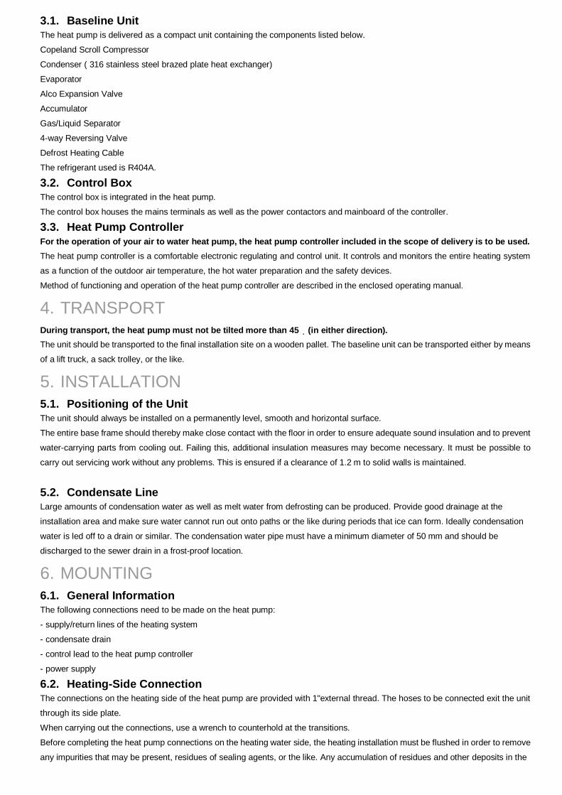
3.1. Baseline Unit The heat pump is delivered as a compact unit containing the components listed below.
Copeland Scroll Compressor
Condenser ( 316 stainless steel brazed plate heat exchanger)
Evaporator
Alco Expansion Valve
Accumulator
Gas/Liquid Separator
4-way Reversing Valve
Defrost Heating Cable
The refrigerant used is R404A.
3.2. Control Box The control box is integrated in the heat pump.
The control box houses the mains terminals as well as the power contactors and mainboard of the controller.
3.3. Heat Pump Controller For the operation of your air to water heat pump, the heat pump controller included in the scope of delivery is to be used. The heat pump controller is a comfortable electronic regulating and control unit. It controls and monitors the entire heating system
as a function of the outdoor air temperature, the hot water preparation and the safety devices.
Method of functioning and operation of the heat pump controller are described in the enclosed operating manual.
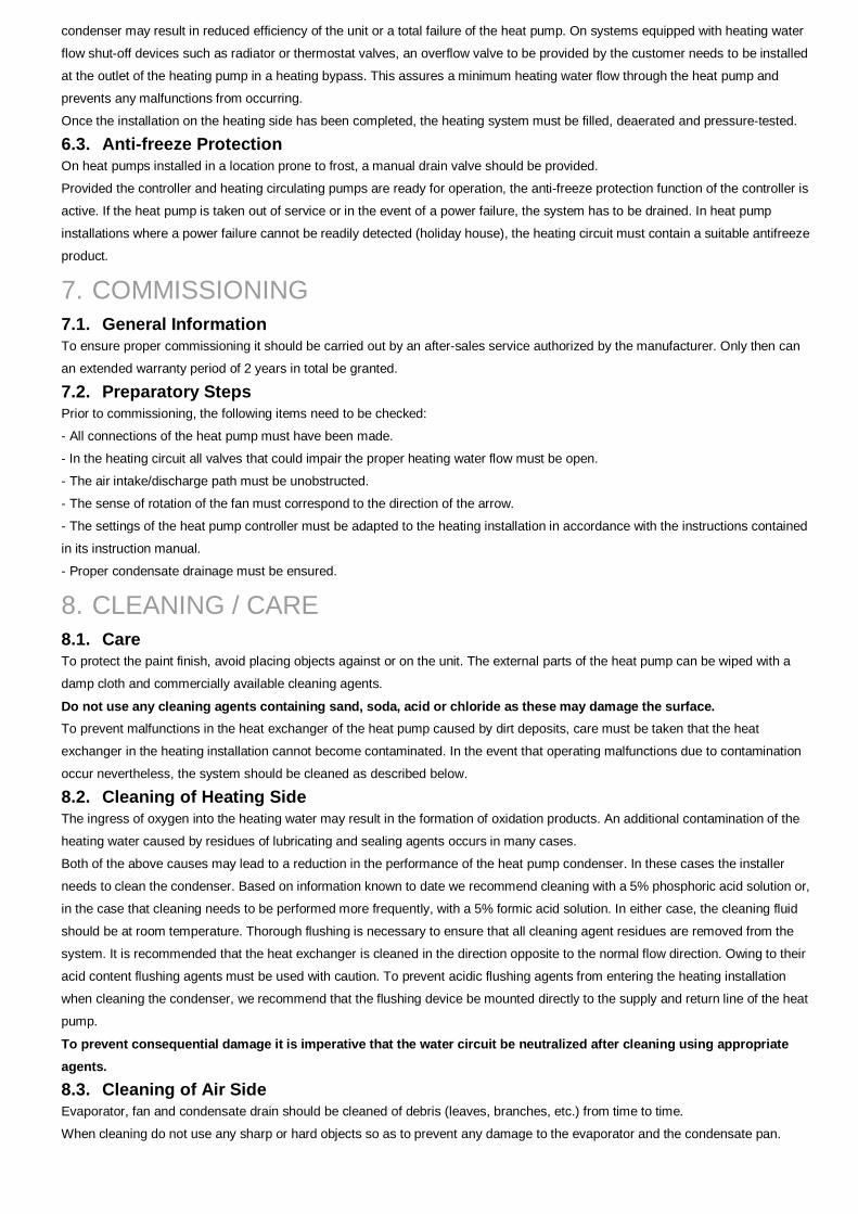
4. TRANSPORT During transport, the heat pump must not be tilted more than 45 (in either direction). The unit should be transported to the final installation site on a wooden pallet. The baseline unit can be transported either by means
of a lift truck, a sack trolley, or the like.
5. INSTALLATION 5.1. Positioning of the Unit The unit should always be installed on a permanently level, smooth and horizontal surface.
The entire base frame should thereby make close contact with the floor in order to ensure adequate sound insulation and to prevent
water-carrying parts from cooling out. Failing this, additional insulation measures may become necessary. It must be possible to
carry out servicing work without any problems. This is ensured if a clearance of 1.2 m to solid walls is maintained.
5.2. Condensate Line Large amounts of condensation water as well as melt water from defrosting can be produced. Provide good drainage at the
installation area and make sure water cannot run out onto paths or the like during periods that ice can form. Ideally condensation
water is led off to a drain or similar. The condensation water pipe must have a minimum diameter of 50 mm and should be
discharged to the sewer drain in a frost-proof location.
6. MOUNTING 6.1. General Information The following connections need to be made on the heat pump:
- supply/return lines of the heating system
- condensate drain
- control lead to the heat pump controller
- power supply
6.2. Heating-Side Connection The connections on the heating side of the heat pump are provided with 1"external thread. The hoses to be connected exit the unit
through its side plate.
When carrying out the connections, use a wrench to counterhold at the transitions.
Before completing the heat pump connections on the heating water side, the heating installation must be flushed in order to remove
any impurities that may be present, residues of sealing agents, or the like. Any accumulation of residues and other deposits in the
condenser may result in reduced efficiency of the unit or a total failure of the heat pump. On systems equipped with heating water
flow shut-off devices such as radiator or thermostat valves, an overflow valve to be provided by the customer needs to be installed
at the outlet of the heating pump in a heating bypass. This assures a minimum heating water flow through the heat pump and
prevents any malfunctions from occurring.
Once the installation on the heating side has been completed, the heating system must be filled, deaerated and pressure-tested.
6.3. Anti-freeze Protection On heat pumps installed in a location prone to frost, a manual drain valve should be provided.
Provided the controller and heating circulating pumps are ready for operation, the anti-freeze protection function of the controller is
active. If the heat pump is taken out of service or in the event of a power failure, the system has to be drained. In heat pump
installations where a power failure cannot be readily detected (holiday house), the heating circuit must contain a suitable antifreeze
product.
7. COMMISSIONING 7.1. General Information To ensure proper commissioning it should be carried out by an after-sales service authorized by the manufacturer. Only then can
an extended warranty period of 2 years in total be granted. 7.2. Preparatory Steps Prior to commissioning, the following items need to be checked:
- All connections of the heat pump must have been made.
- In the heating circuit all valves that could impair the proper heating water flow must be open.
- The air intake/discharge path must be unobstructed.
- The sense of rotation of the fan must correspond to the direction of the arrow.
- The settings of the heat pump controller must be adapted to the heating installation in accordance with the instructions contained
in its instruction manual.
- Proper condensate drainage must be ensured.
8. CLEANING / CARE 8.1. Care To protect the paint finish, avoid placing objects against or on the unit. The external parts of the heat pump can be wiped with a
damp cloth and commercially available cleaning agents.
Do not use any cleaning agents containing sand, soda, acid or chloride as these may damage the surface. To prevent malfunctions in the heat exchanger of the heat pump caused by dirt deposits, care must be taken that the heat
exchanger in the heating installation cannot become contaminated. In the event that operating malfunctions due to contamination
occur nevertheless, the system should be cleaned as described below.
8.2. Cleaning of Heating Side The ingress of oxygen into the heating water may result in the formation of oxidation products. An additional contamination of the
heating water caused by residues of lubricating and sealing agents occurs in many cases.
Both of the above causes may lead to a reduction in the performance of the heat pump condenser. In these cases the installer
needs to clean the condenser. Based on information known to date we recommend cleaning with a 5% phosphoric acid solution or,
in the case that cleaning needs to be performed more frequently, with a 5% formic acid solution. In either case, the cleaning fluid
should be at room temperature. Thorough flushing is necessary to ensure that all cleaning agent residues are removed from the
system. It is recommended that the heat exchanger is cleaned in the direction opposite to the normal flow direction. Owing to their
acid content flushing agents must be used with caution. To prevent acidic flushing agents from entering the heating installation
when cleaning the condenser, we recommend that the flushing device be mounted directly to the supply and return line of the heat
pump.
To prevent consequential damage it is imperative that the water circuit be neutralized after cleaning using appropriate agents.
8.3. Cleaning of Air Side Evaporator, fan and condensate drain should be cleaned of debris (leaves, branches, etc.) from time to time.
When cleaning do not use any sharp or hard objects so as to prevent any damage to the evaporator and the condensate pan.
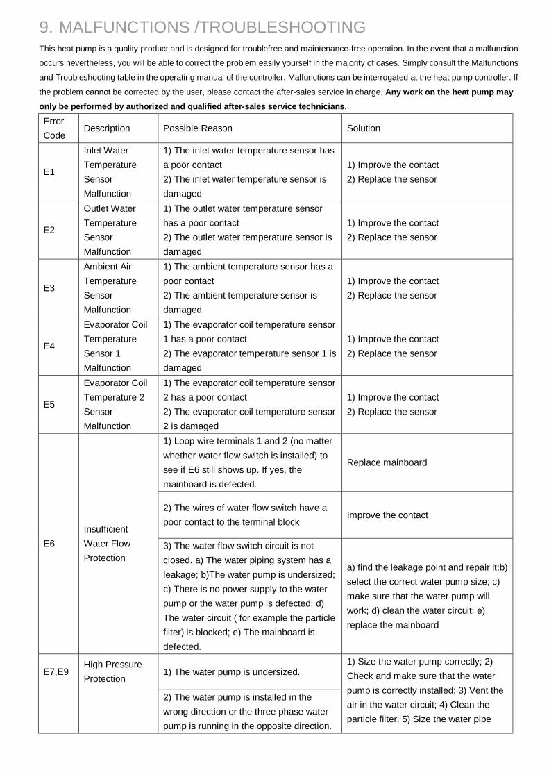
9. MALFUNCTIONS /TROUBLESHOOTING This heat pump is a quality product and is designed for troublefree and maintenance-free operation. In the event that a malfunction
occurs nevertheless, you will be able to correct the problem easily yourself in the majority of cases. Simply consult the Malfunctions
and Troubleshooting table in the operating manual of the controller. Malfunctions can be interrogated at the heat pump controller. If
the problem cannot be corrected by the user, please contact the after-sales service in charge. Any work on the heat pump may only be performed by authorized and qualified after-sales service technicians.
Error Code
Description Possible Reason Solution
E1
Inlet Water Temperature Sensor Malfunction
1) The inlet water temperature sensor has a poor contact 2) The inlet water temperature sensor is damaged
1) Improve the contact 2) Replace the sensor
E2
Outlet Water Temperature Sensor Malfunction
1) The outlet water temperature sensor has a poor contact 2) The outlet water temperature sensor is damaged
1) Improve the contact 2) Replace the sensor
E3
Ambient Air Temperature Sensor Malfunction
1) The ambient temperature sensor has a poor contact 2) The ambient temperature sensor is damaged
1) Improve the contact 2) Replace the sensor
E4
Evaporator Coil Temperature Sensor 1 Malfunction
1) The evaporator coil temperature sensor 1 has a poor contact 2) The evaporator temperature sensor 1 is damaged
1) Improve the contact 2) Replace the sensor
E5
Evaporator Coil Temperature 2 Sensor Malfunction
1) The evaporator coil temperature sensor 2 has a poor contact 2) The evaporator coil temperature sensor 2 is damaged
1) Improve the contact 2) Replace the sensor
1) Loop wire terminals 1 and 2 (no matter whether water flow switch is installed) to see if E6 still shows up. If yes, the mainboard is defected.
Replace mainboard
2) The wires of water flow switch have a poor contact to the terminal block
Improve the contact
E6 Insufficient Water Flow Protection
3) The water flow switch circuit is not closed. a) The water piping system has a leakage; b)The water pump is undersized; c) There is no power supply to the water pump or the water pump is defected; d) The water circuit ( for example the particle filter) is blocked; e) The mainboard is defected.
a) find the leakage point and repair it;b) select the correct water pump size; c) make sure that the water pump will work; d) clean the water circuit; e) replace the mainboard
1) The water pump is undersized. E7,E9 High Pressure Protection
2) The water pump is installed in the wrong direction or the three phase water pump is running in the opposite direction.
1) Size the water pump correctly; 2) Check and make sure that the water pump is correctly installed; 3) Vent the air in the water circuit; 4) Clean the particle filter; 5) Size the water pipe
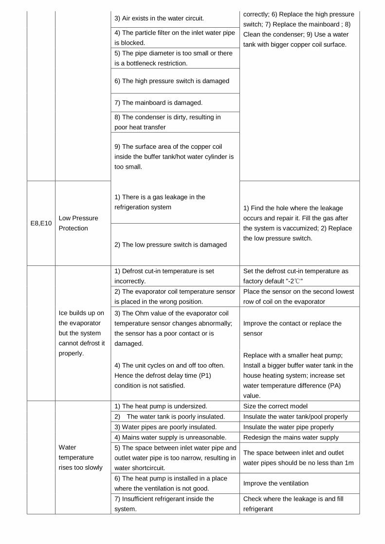
3) Air exists in the water circuit.
4) The particle filter on the inlet water pipe is blocked. 5) The pipe diameter is too small or there is a bottleneck restriction.
6) The high pressure switch is damaged
7) The mainboard is damaged.
8) The condenser is dirty, resulting in poor heat transfer
9) The surface area of the copper coil inside the buffer tank/hot water cylinder is too small.
correctly; 6) Replace the high pressure switch; 7) Replace the mainboard ; 8) Clean the condenser; 9) Use a water tank with bigger copper coil surface.
1) There is a gas leakage in the refrigeration system
E8,E10 Low Pressure Protection
2) The low pressure switch is damaged
1) Find the hole where the leakage occurs and repair it. Fill the gas after the system is vaccumized; 2) Replace the low pressure switch.
1) Defrost cut-in temperature is set incorrectly.
Set the defrost cut-in temperature as factory default "-2 " ℃
2) The evaporator coil temperature sensor is placed in the wrong position.
Place the sensor on the second lowest row of coil on the evaporator
3) The Ohm value of the evaporator coil temperature sensor changes abnormally; the sensor has a poor contact or is damaged.
Improve the contact or replace the sensor
Ice builds up on the evaporator but the system cannot defrost it properly.
4) The unit cycles on and off too often. Hence the defrost delay time (P1) condition is not satisfied.
Replace with a smaller heat pump; Install a bigger buffer water tank in the house heating system; increase set water temperature difference (PA) value.
1) The heat pump is undersized. Size the correct model 2) The water tank is poorly insulated. Insulate the water tank/pool properly 3) Water pipes are poorly insulated. Insulate the water pipe properly 4) Mains water supply is unreasonable. Redesign the mains water supply 5) The space between inlet water pipe and outlet water pipe is too narrow, resulting in water shortcircuit.
The space between inlet and outlet water pipes should be no less than 1m
6) The heat pump is installed in a place where the ventilation is not good.
Improve the ventilation
Water temperature rises too slowly
7) Insufficient refrigerant inside the system.
Check where the leakage is and fill refrigerant
1) The phase sequence board in the electrical box activates fault-phase or lack-phase protection
Check if there is a lack-phase and put the phase wire in the right position
Water pump and fan motor is running, but the compressor does not start 2) Phase sequence board is damaged Replace the phase sequence board
1) No power input Plug in the power cord
2) Power voltage is not correct Start the heat pump under the right voltage
3) Power voltage drops when the unit is started. The unit draws a huge current.
Low power capacity in the network; Wires in wrong diameter (too small) are used.
4) Fault-phase or lack-phase problem with the mains power supply.
Put the phase wires in the right position
5) Poor contact problem with the wiring in the system.
Improve the contact
6) The heat pump is in clock timer shutdown state.
Check the clock timer settings. Reset or cancel it.
7) The system is in protection. Check what kind of protection it is and remedy it.
Heat pump does not start properly
8) Damaged mainboard or damaged temperature sensor.
Replace the mainboard or sensor
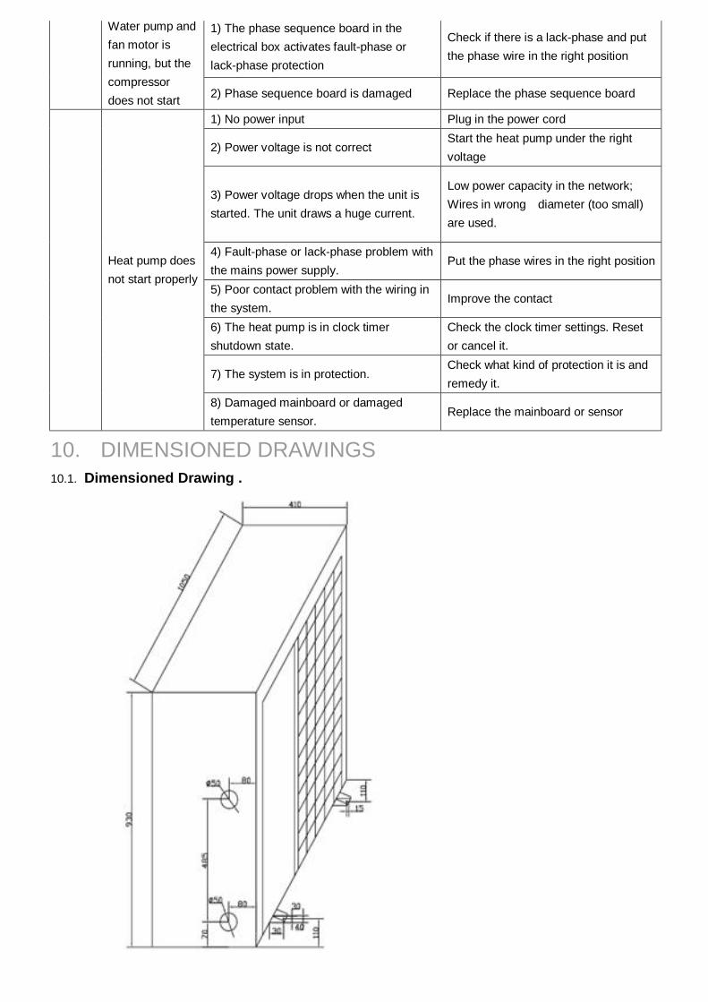
10. DIMENSIONED DRAWINGS 10.1. Dimensioned Drawing . 10.2.
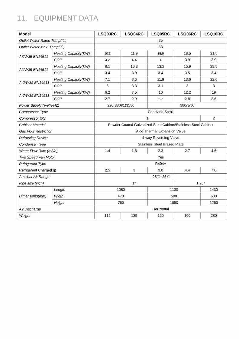
11. EQUIPMENT DATA Model LSQ03RC LSQ04RC LSQ05RC LSQ06RC LSQ10RC Outlet Water Rated Temp(℃) 35
Outlet Water Max. Temp(℃) 58
Heating Capacity(KW) 10.3 11.9 15.9 18.5 31.5 A7/W35 EN14511
COP 4.2 4.4 4 3.9 3.9
Heating Capacity(KW) 8.1 10.3 13.2 15.9 25.5 A2/W35 EN14511
COP 3.4 3.9 3.4 3.5 3.4
Heating Capacity(KW) 7.1 8.6 11.9 13.6 22.6 A-2/W35 EN14511
COP 3 3.3 3.1 3 3
Heating Capacity(KW) 6.2 7.5 10 12.2 19 A-7/W35 EN14511
COP 2.7 2.9 2.7 2.8 2.6
Power Supply (V/PH/HZ) 220(380)/1(3)/50 380/3/50
Compressor Type Copeland Scroll
Compressor Qty 1 2
Cabinet Material Powder Coated Galvanized Steel Cabinet/Stainless Steel Cabinet
Gas Flow Restriction Alco Thermal Expansion Valve
Defrosting Device 4-way Reversing Valve
Condenser Type Stainless Steel Brazed Plate
Water Flow Rate (m3/h) 1.4 1.8 2.3 2.7 4.6
Two Speed Fan Motor Yes
Refrigerant Type R404A
Refrigerant Charge(kg) 2.5 3 3.8 4.4 7.6
Ambient Air Range -25℃~35℃
Pipe size (inch) 1" 1.25"
Length 1080 1130 1430
Width 470 500 600 Dimensions(mm)
Height 760 1050 1260
Air Discharge Horizontal
Weight 115 135 150 160 280

12. WIRING DIAGRAMS
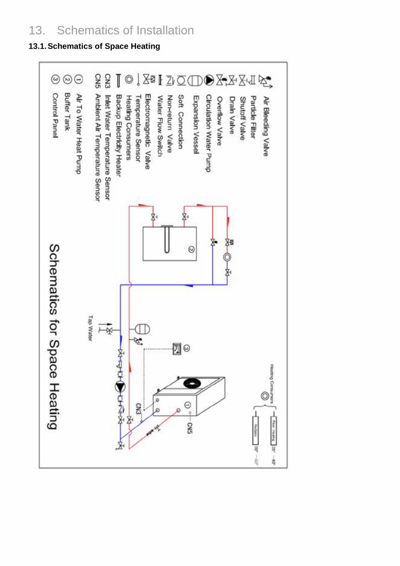
13. Schematics of Installation 13.1. Schematics of Space Heating
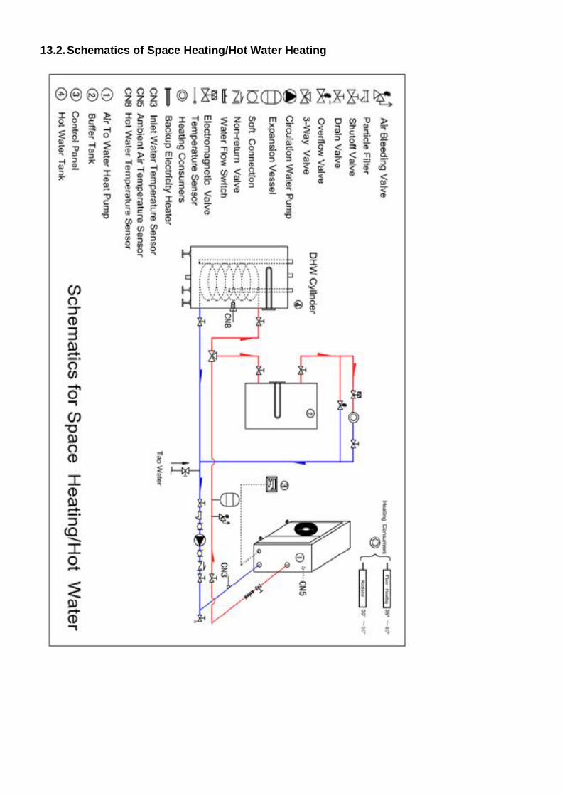
13.2. Schematics of Space Heating/Hot Water Heating
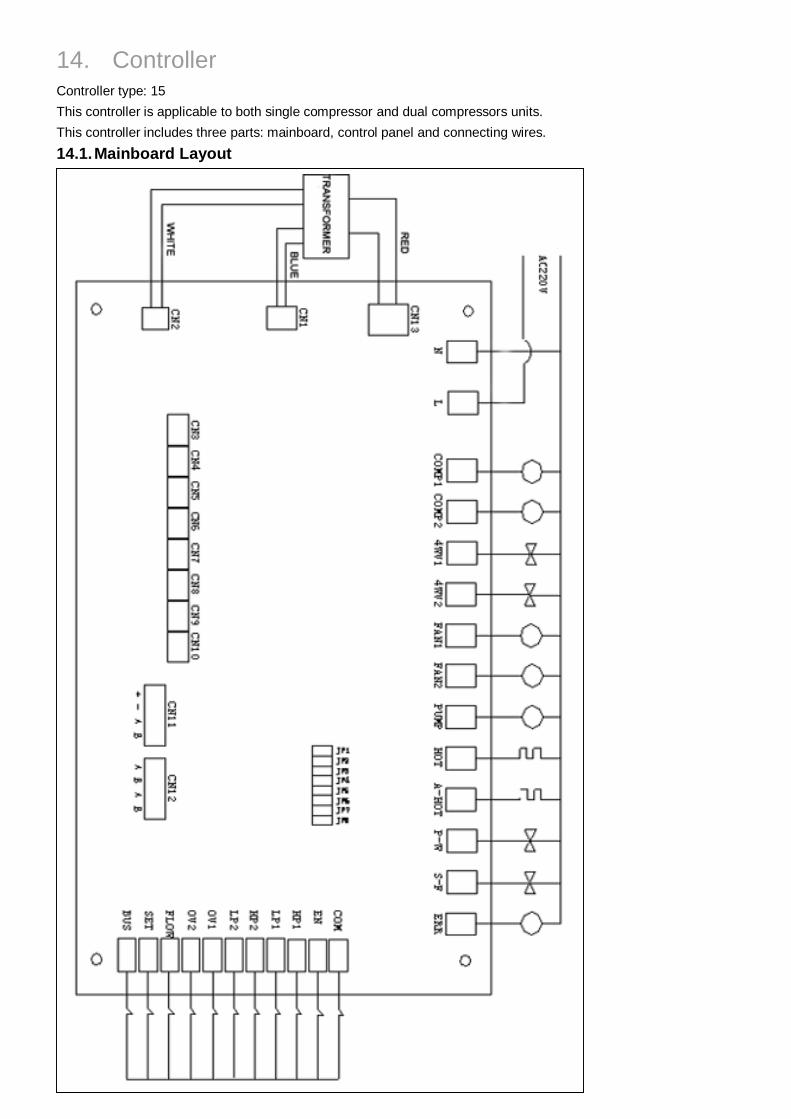
14. Controller Controller type: 15 This controller is applicable to both single compressor and dual compressors units. This controller includes three parts: mainboard, control panel and connecting wires. 14.1. Mainboard Layout
COMP1: Compressor 1 COMP2: Compressor 2 4WV1: 4-way Reversing Valve 1 4WV2: 4-way Reversing Valve 2 FAN1: Fan Motor, Low Speed FAN2: Fan Motor, High Speed PUMP: Water Pump HOT: Backup Electricity Heater A-HOT: Crankcase Heater P-W: Solenoid for Hot Water S-F: Solenoid for Defrost Heating Cable ERR: Error Light CN3 : Inlet Water Temperature Sensor CN4 : Outlet Water Temperature Sensor CN5 : Ambient Temperature Sensor CN6 : Evaporator Coil Temperature 1 Sensor CN7 : Evaporator Coil Temperature 2 Sensor CN8 : Hot Water Temperature Sensor CN9 : Gas Discharge Temperature 1 Sensor CN10: Gas Discharge Temperature 2 Sensor CN11: Control Panel CN12: Assist Unit COM: Common Port EN: Interlock Signal HP1: High Pressure Protection 1 LP1: Low Pressure Protection 1 HP2: High Pressure Protection 2 LP2: Low Pressure Protection 2 OV1: Compressor 1 Overload OV2: Compressor 2 Overload FLOW: Water Flow Switch SET: Anti-freeze Protection BUS: Comprehensive Protection 14.2. Jumper Settings
State Function Switch
Disconnected Loop Wired Remarks
JP1 Equipments Self-checkup. User regulation not allowed.
JP2 Both Systems Valid System 1 Valid Only JP3 Backup JP4 Backup
Jumpers 5, 6,7 and 8 are used to set Duty/Assist Unit No.
JP8 JP7 JP6 JP5 Unit 0 0 0 0 No. 1 ( Duty) 0 0 0 1 No. 2 (Assist) 0 0 1 0 No. 3 (Assist)
0 0 1 1 No. 4 (Assist) 0 1 0 0 No. 5 (Assist) 0 1 0 1 No. 6 (Assist) 0 1 1 0 No. 7 (Assist) 0 1 1 1 No. 8 (Assist) 1 0 0 0 No. 9 (Assist) 1 0 0 1 No. 10 (Assist)
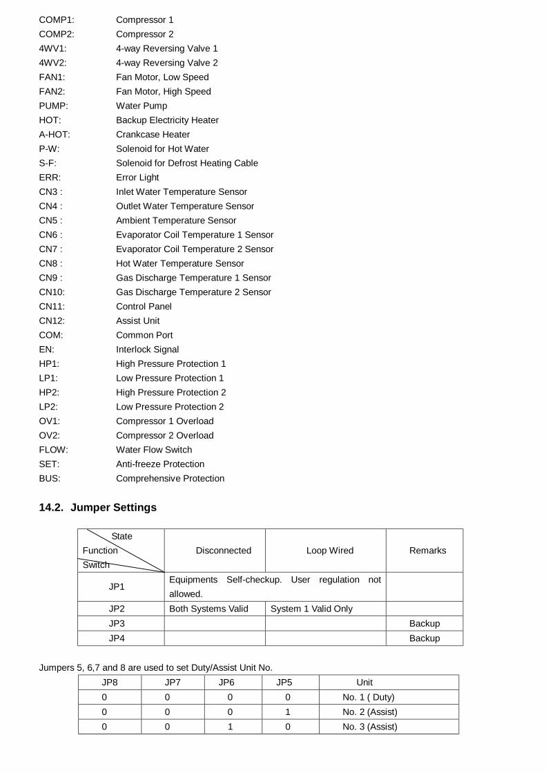
X X X X Invalid 14.3. Control Panel ON/OFF Press ON/OFF to switch on/off the unit.
MODE Press MODE to select the running mode. Mode selection is valid only when the compressor is off. Cooling Mode: the unit will cool the water till the water temperature reaches the set point. Heating Mode: the unit will heat the water till the water temperature reached the set point. Auto Mode: the unit will cool the water till the water temperature reaches the set point, and automatically heat the water till the water temperature reaches the set point. Note: Hot water heating mode can only be activated in parameter setting.
RESET
When an error code is displayed on the screen, press RESET. If the error is rectified, the error code will disappear. If the error is not rectified, the error code will remain on the screen. ▲ Press ▲to set the parameter value upwards by 1 degree or 1 min. ▼ Press ▼to set the parameter value upwards by 1 degree or 1 min. When the unit is off, the user can hold ▼ for 5 seconds to enter forced defrost mode even if the defrost cut-in conditions are not satisfied. Note: to set water temperature for heating/cooling, switch on the control panel ( ON/OFF), and then press ▲or ▼to adjust the set water temperature.
TIMER (24hours/7days) Press TIMER and then ▲ ▼ to set unit automatic on/off time. First Press: set HOUR digit for unit automatic on; Second Press: set MINUTE digit for unit automatic on; Third Press: set HOUR digit for unit automatic off; Fourth Press: set MINUTE digit for unit automatic off. Fifth Press: exit Timer state. Note: when the set times are the same, the timer setting will become invalid. Hold Timer Button for five seconds to set clock time. First Press: set HOUR digit of the clock time. Second Press: set MINUTE digit clock time. Third Press: exit clock time setting. Note: if no action is made in five seconds, the controller will exit setting state. When both unit automatic on and automatic off times are set, every day the unit will run according to this setting LANG Press this button to select the Unit Number for running parameters checkup (if multiple units are installed in one project and modular control function is in use).
SET Press SET button directly to check running parameters. If the unit No. shown on the display is “1”, the displayed parameters are from the duty unit. Otherwise the displayed parameters are from the assist unit (depending on the Unit Number set on LANG. 14.4. Running Parameter Checkup
Duty Unit Item Parameter Name Unit
1 Inlet Water Temp ℃
2 Outlet Water Temp ℃
3 Ambient Air Temp ℃
4 Evaporator Coil Temp 1 ℃
5 Evaporator Coil Temp 2 ℃
6 Hot Water Temp ℃
7 Discharge Gas Temp Compressor 1 ℃
8 Discharge Gas Temp Compressor 2 ℃
Assist Unit
Item Parameter Description Unit
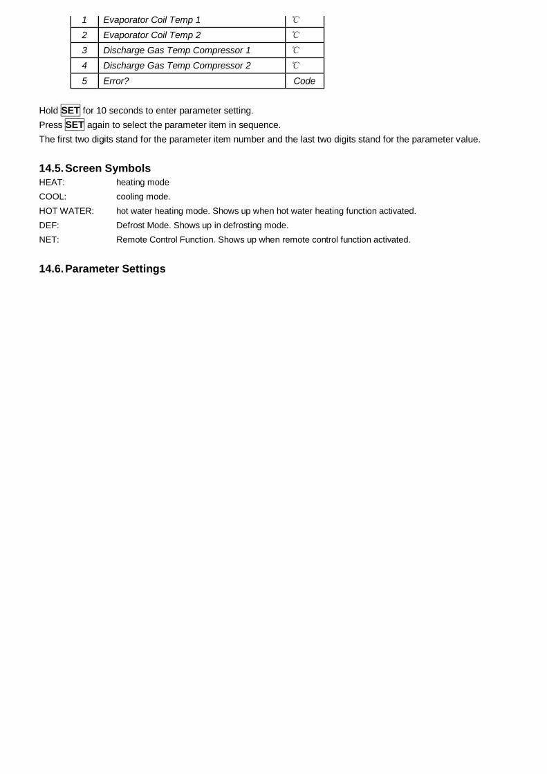
1 Evaporator Coil Temp 1 ℃
2 Evaporator Coil Temp 2 ℃
3 Discharge Gas Temp Compressor 1 ℃
4 Discharge Gas Temp Compressor 2 ℃
5 Error? Code Hold SET for 10 seconds to enter parameter setting. Press SET again to select the parameter item in sequence. The first two digits stand for the parameter item number and the last two digits stand for the parameter value.
14.5. Screen Symbols HEAT: heating mode COOL: cooling mode. HOT WATER: hot water heating mode. Shows up when hot water heating function activated. DEF: Defrost Mode. Shows up in defrosting mode. NET: Remote Control Function. Shows up when remote control function activated.
14.6. Parameter Settings
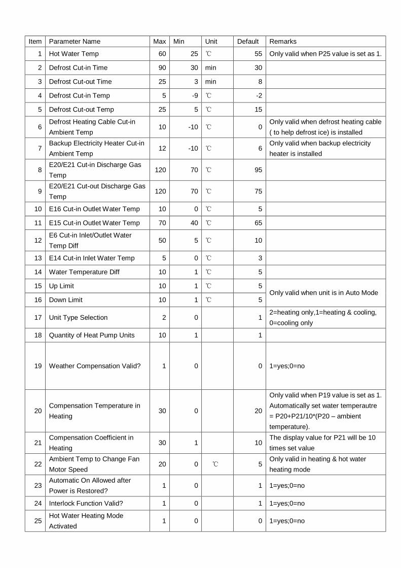
Item Parameter Name Max Min Unit Default Remarks
1 Hot Water Temp 60 25 ℃ 55 Only valid when P25 value is set as 1.
2 Defrost Cut-in Time 90 30 min 30
3 Defrost Cut-out Time 25 3 min 8
4 Defrost Cut-in Temp 5 -9 ℃ -2
5 Defrost Cut-out Temp 25 5 ℃ 15
6 Defrost Heating Cable Cut-in Ambient Temp
10 -10 ℃ 0 Only valid when defrost heating cable ( to help defrost ice) is installed
7 Backup Electricity Heater Cut-in Ambient Temp
12 -10 ℃ 6 Only valid when backup electricity heater is installed
8 E20/E21 Cut-in Discharge Gas Temp
120 70 ℃ 95
9 E20/E21 Cut-out Discharge Gas Temp
120 70 ℃ 75
10 E16 Cut-in Outlet Water Temp 10 0 ℃ 5
11 E15 Cut-in Outlet Water Temp 70 40 ℃ 65
12 E6 Cut-in Inlet/Outlet Water Temp Diff
50 5 ℃ 10
13 E14 Cut-in Inlet Water Temp 5 0 ℃ 3
14 Water Temperature Diff 10 1 ℃ 5
15 Up Limit 10 1 ℃ 5
16 Down Limit 10 1 ℃ 5 Only valid when unit is in Auto Mode
17 Unit Type Selection 2 0 1 2=heating only,1=heating & cooling, 0=cooling only
18 Quantity of Heat Pump Units 10 1 1
19 Weather Compensation Valid? 1 0 0 1=yes;0=no
20 Compensation Temperature in Heating
30 0 20
Only valid when P19 value is set as 1. Automatically set water temperautre = P20+P21/10*(P20 – ambient temperature).
21 Compensation Coefficient in Heating
30 1 10 The display value for P21 will be 10 times set value
22 Ambient Temp to Change Fan Motor Speed
20 0 ℃ 5 Only valid in heating & hot water heating mode
23 Automatic On Allowed after Power is Restored?
1 0 1 1=yes;0=no
24 Interlock Function Valid? 1 0 1 1=yes;0=no
25 Hot Water Heating Mode Activated
1 0 0 1=yes;0=no
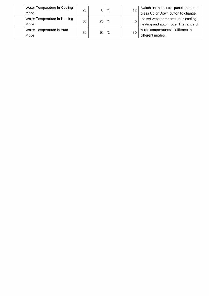
Water Temperature In Cooling Mode
25 8 ℃ 12
Water Temperature In Heating Mode
60 25 ℃ 40
Water Temperature in Auto Mode
50 10 ℃ 30
Switch on the control panel and then press Up or Down button to change the set water temperature in cooling, heating and auto mode. The range of water temperatures is different in different modes.
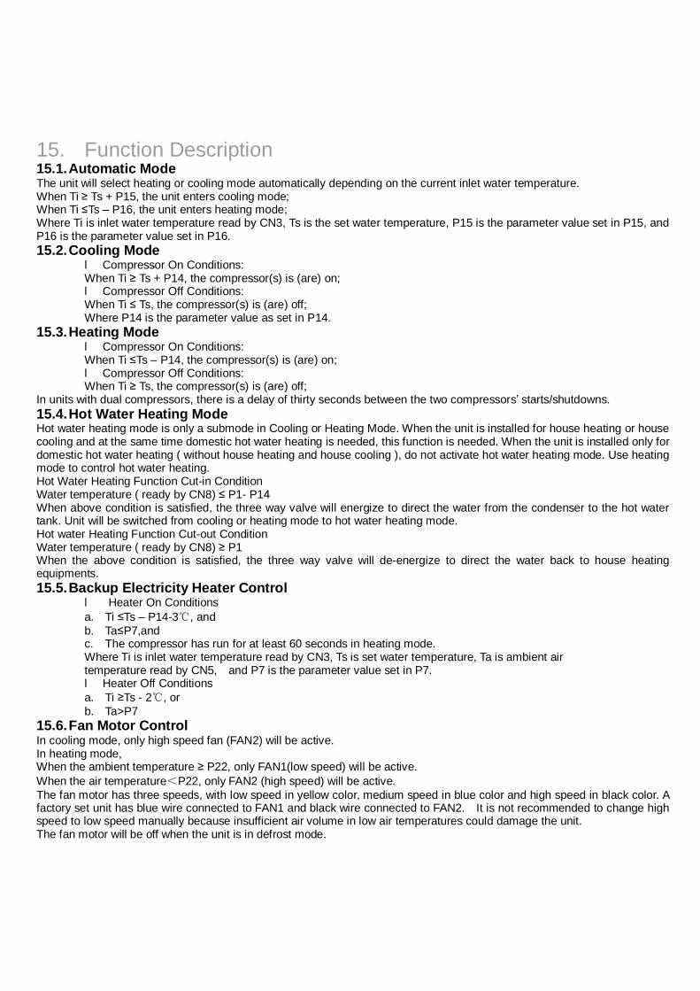
15. Function Description 15.1. Automatic Mode The unit will select heating or cooling mode automatically depending on the current inlet water temperature. When Ti ≥ Ts + P15, the unit enters cooling mode; When Ti ≤Ts – P16, the unit enters heating mode; Where Ti is inlet water temperature read by CN3, Ts is the set water temperature, P15 is the parameter value set in P15, and P16 is the parameter value set in P16. 15.2. Cooling Mode
l Compressor On Conditions: When Ti ≥ Ts + P14, the compressor(s) is (are) on; l Compressor Off Conditions: When Ti ≤ Ts, the compressor(s) is (are) off; Where P14 is the parameter value as set in P14.
15.3. Heating Mode l Compressor On Conditions: When Ti ≤Ts – P14, the compressor(s) is (are) on; l Compressor Off Conditions: When Ti ≥ Ts, the compressor(s) is (are) off;
In units with dual compressors, there is a delay of thirty seconds between the two compressors’ starts/shutdowns. 15.4. Hot Water Heating Mode Hot water heating mode is only a submode in Cooling or Heating Mode. When the unit is installed for house heating or house cooling and at the same time domestic hot water heating is needed, this function is needed. When the unit is installed only for domestic hot water heating ( without house heating and house cooling ), do not activate hot water heating mode. Use heating mode to control hot water heating. Hot Water Heating Function Cut-in Condition Water temperature ( ready by CN8) ≤ P1- P14 When above condition is satisfied, the three way valve will energize to direct the water from the condenser to the hot water tank. Unit will be switched from cooling or heating mode to hot water heating mode. Hot water Heating Function Cut-out Condition Water temperature ( ready by CN8) ≥ P1 When the above condition is satisfied, the three way valve will de-energize to direct the water back to house heating equipments. 15.5. Backup Electricity Heater Control
l Heater On Conditions a. Ti ≤Ts – P14-3℃, and b. Ta≤P7,and c. The compressor has run for at least 60 seconds in heating mode. Where Ti is inlet water temperature read by CN3, Ts is set water temperature, Ta is ambient air temperature read by CN5, and P7 is the parameter value set in P7. l Heater Off Conditions a. Ti ≥Ts - 2℃, or b. Ta>P7
15.6. Fan Motor Control In cooling mode, only high speed fan (FAN2) will be active. In heating mode, When the ambient temperature ≥ P22, only FAN1(low speed) will be active. When the air temperature<P22, only FAN2 (high speed) will be active. The fan motor has three speeds, with low speed in yellow color, medium speed in blue color and high speed in black color. A factory set unit has blue wire connected to FAN1 and black wire connected to FAN2. It is not recommended to change high speed to low speed manually because insufficient air volume in low air temperatures could damage the unit. The fan motor will be off when the unit is in defrost mode.
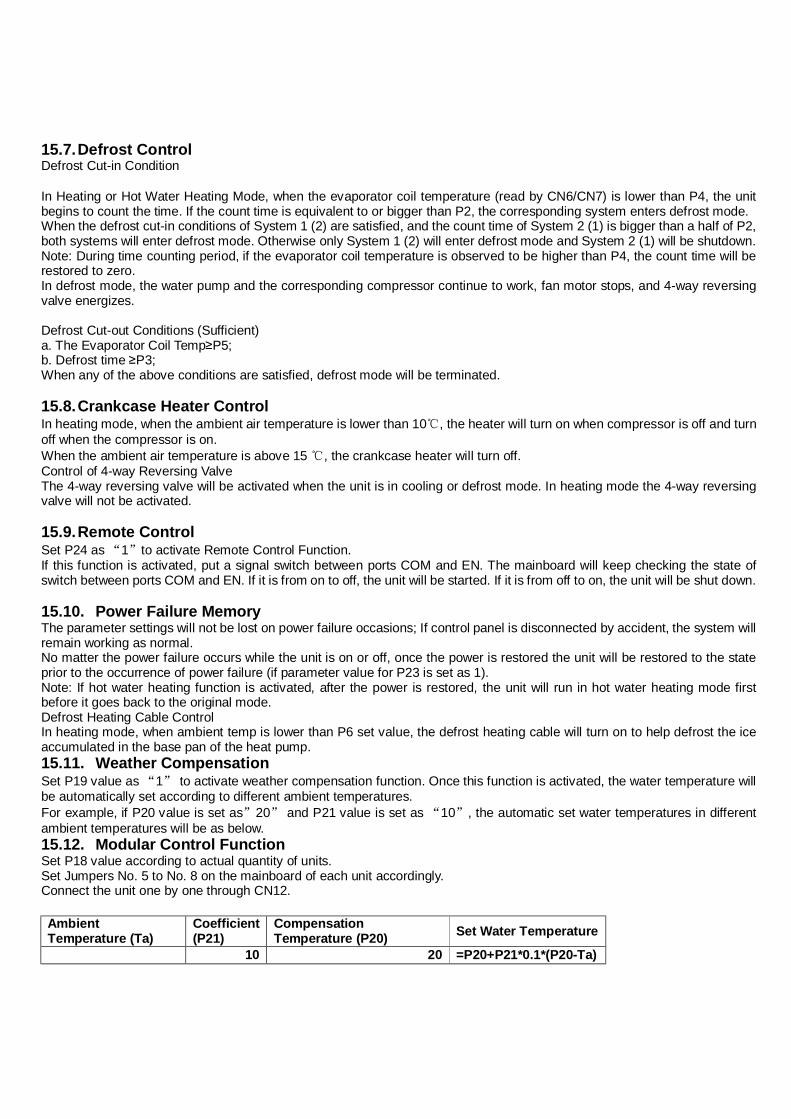
15.7. Defrost Control Defrost Cut-in Condition
In Heating or Hot Water Heating Mode, when the evaporator coil temperature (read by CN6/CN7) is lower than P4, the unit begins to count the time. If the count time is equivalent to or bigger than P2, the corresponding system enters defrost mode. When the defrost cut-in conditions of System 1 (2) are satisfied, and the count time of System 2 (1) is bigger than a half of P2, both systems will enter defrost mode. Otherwise only System 1 (2) will enter defrost mode and System 2 (1) will be shutdown. Note: During time counting period, if the evaporator coil temperature is observed to be higher than P4, the count time will be restored to zero. In defrost mode, the water pump and the corresponding compressor continue to work, fan motor stops, and 4-way reversing valve energizes.
Defrost Cut-out Conditions (Sufficient) a. The Evaporator Coil Temp≥P5; b. Defrost time ≥P3; When any of the above conditions are satisfied, defrost mode will be terminated. 15.8. Crankcase Heater Control In heating mode, when the ambient air temperature is lower than 10℃, the heater will turn on when compressor is off and turn off when the compressor is on. When the ambient air temperature is above 15 ℃, the crankcase heater will turn off. Control of 4-way Reversing Valve The 4-way reversing valve will be activated when the unit is in cooling or defrost mode. In heating mode the 4-way reversing valve will not be activated. 15.9. Remote Control Set P24 as “1”to activate Remote Control Function. If this function is activated, put a signal switch between ports COM and EN. The mainboard will keep checking the state of switch between ports COM and EN. If it is from on to off, the unit will be started. If it is from off to on, the unit will be shut down. 15.10. Power Failure Memory The parameter settings will not be lost on power failure occasions; If control panel is disconnected by accident, the system will remain working as normal. No matter the power failure occurs while the unit is on or off, once the power is restored the unit will be restored to the state prior to the occurrence of power failure (if parameter value for P23 is set as 1). Note: If hot water heating function is activated, after the power is restored, the unit will run in hot water heating mode first before it goes back to the original mode. Defrost Heating Cable Control In heating mode, when ambient temp is lower than P6 set value, the defrost heating cable will turn on to help defrost the ice accumulated in the base pan of the heat pump. 15.11. Weather Compensation Set P19 value as “1” to activate weather compensation function. Once this function is activated, the water temperature will be automatically set according to different ambient temperatures. For example, if P20 value is set as”20” and P21 value is set as “10”, the automatic set water temperatures in different ambient temperatures will be as below. 15.12. Modular Control Function Set P18 value according to actual quantity of units. Set Jumpers No. 5 to No. 8 on the mainboard of each unit accordingly. Connect the unit one by one through CN12. Ambient Temperature (Ta)
Coefficient (P21)
Compensation Temperature (P20) Set Water Temperature
10 20 =P20+P21*0.1*(P20-Ta)
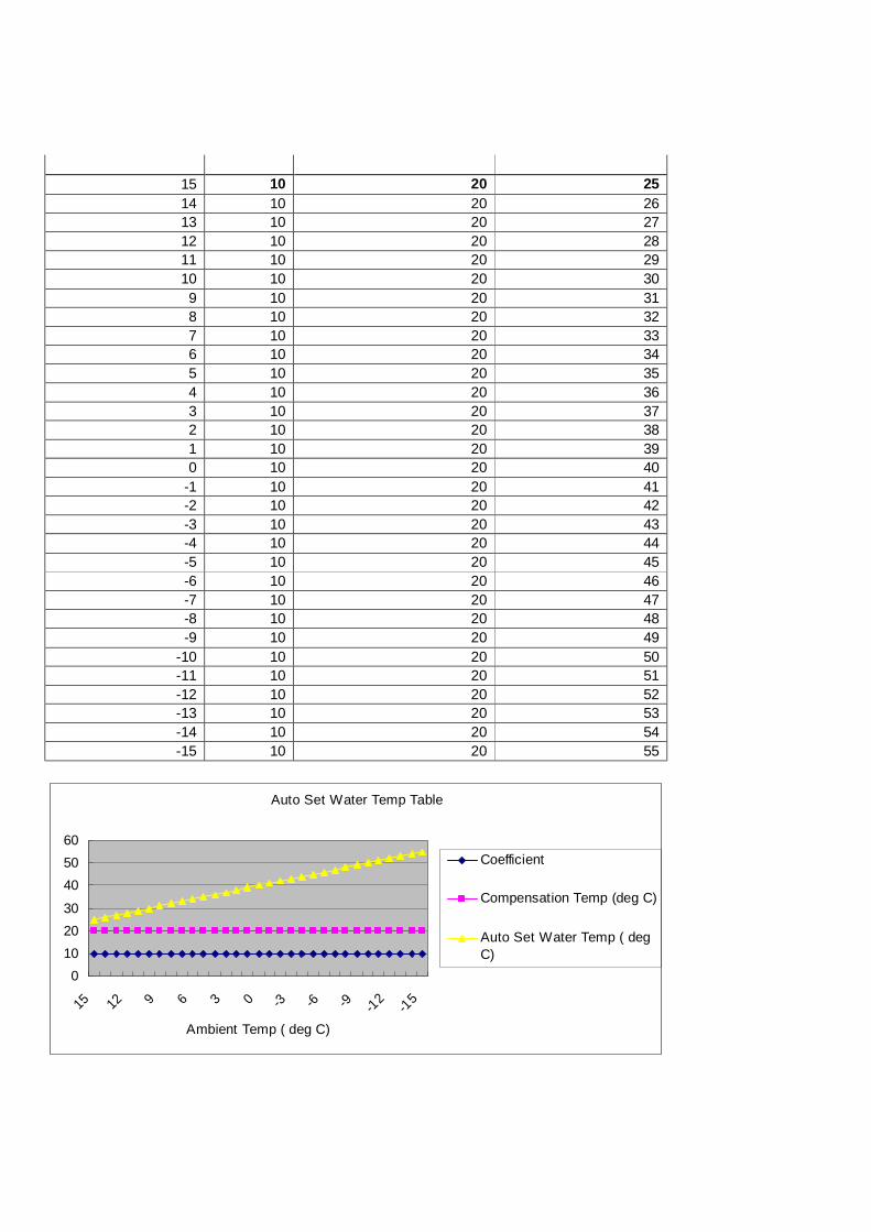
15 10 20 25 14 10 20 26 13 10 20 27 12 10 20 28 11 10 20 29 10 10 20 30 9 10 20 31 8 10 20 32 7 10 20 33 6 10 20 34 5 10 20 35 4 10 20 36 3 10 20 37 2 10 20 38 1 10 20 39 0 10 20 40
-1 10 20 41 -2 10 20 42 -3 10 20 43 -4 10 20 44 -5 10 20 45 -6 10 20 46 -7 10 20 47 -8 10 20 48 -9 10 20 49
-10 10 20 50 -11 10 20 51 -12 10 20 52 -13 10 20 53 -14 10 20 54 -15 10 20 55
Auto Set Water Temp Table
0102030
405060
15 12 9 6 3 0 -3 -6 -9 -12 -15
Ambient Temp ( deg C)
Coefficient
Compensation Temp (deg C)
Auto Set Water Temp ( degC)
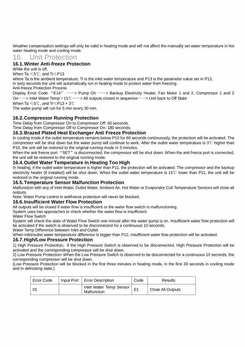
Weather compensation settings will only be valid in heating mode and will not affect the manually set water temperature in hot water heating mode and cooling mode.
16. Unit Protection 16.1. Winter Anti-freeze Protection While the unit is off, When Ta ≤5℃, and Ti≤P13 where Ta is the ambient temperature, Ti is the inlet water temperature and P13 is the parameter value set in P13, in sixty seconds the unit will automatically run in heating mode to protect water from freezing. Anti-freeze Protection Process Display Error Code “E14” ——> Pump On ——> Backup Electricity Heater, Fan Motor 1 and 2, Compressor 1 and 2 On——> Inlet Water Temp>15℃——> All outputs closed in sequence——> Unit back to Off State When Ta ≤5℃, and Ti≤P13 + 3℃ The water pump will run for 5 min every 30 min. 16.2. Compressor Running Protection Time Delay from Compressor On to Compressor Off: 60 seconds. Time Delay from Compressor Off to Compressor On: 180 seconds. 16.3. Brazed Plated Heat Exchanger Anti Freeze Protection In cooling mode,if the outlet temperature remains below P10 for 60 seconds continuously, the protection will be activated. The compressor will be shut down but the water pump will continue to work. After the outlet water temperature is 3℃ higher than P10, the unit will be restored to the original running mode in 3 minutes. When the anti freeze port “SET”is disconnected, the compressor will be shut down. When the anti freeze port is connected, the unit will be restored to the original running mode. 16.4. Outlet Water Temperature in Heating Too High In heating, if the outlet water temperature is higher than P11, the protection will be activated. The compressor and the backup electricity heater (if installed) will be shut down. When the outlet water temperature is 15℃ lower than P11, the unit will be restored to the original running mode. 16.5. Temperature Sensor Malfunction Protection Malfunction with any of Inlet Water, Outlet Water, Ambient Air, Hot Water or Evaporator Coil Temperature Sensors will close all outputs. Note: Water Pump control in antifreeze protection will never be blocked. 16.6. Insufficient Water Flow Protection All outputs will be closed if water flow is insufficient or the water flow switch is malfunctioning. System uses two approaches to check whether the water flow is insufficient. Water Flow Switch System will check the state of Water Flow Switch one minute after the water pump is on. Insufficient water flow protection will be activated if the switch is observed to be disconnected for a continuous 10 seconds. Water Temp Difference between Inlet and Outlet When inlet/outlet water temperature difference is bigger than P12, insufficient water flow protection will be activated. 16.7. High/Low Pressure Protection 1) High Pressure Protection:If the High Pressure Switch is observed to be disconnected, High Pressure Protection will be activated and the corresponding compressor will be shut down. 2) Low Pressure Protection: When the Low Pressure Switch is observed to be disconnected for a continuous 10 seconds, the corresponding compressor will be shut down. (Low Pressure Protection will be blocked in the first three minutes in heating mode, in the first 30 seconds in cooling mode and in defrosting state.)
Error Code Input Port Error Description Code Results
01 Inlet Water Temp Sensor Malfunction E1 Close All Outputs
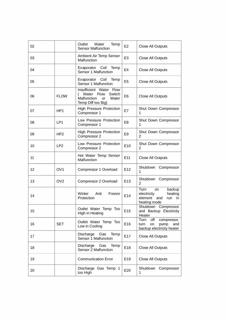
02 Outlet Water Temp Sensor Malfunction E2 Close All Outputs
03 Ambient Air Temp Sensor Malfunction E3 Close All Outputs
04 Evaporator Coil Temp Sensor 1 Malfunction E4 Close All Outputs
05 Evaporator Coil Temp Sensor 1 Malfunction E5 Close All Outputs
06 FLOW
Insufficient Water Flow ( Water Flow Switch Malfunction or Water Temp Diff too Big)
E6 Close All Outputs
07 HP1 High Pressure Protection Compressor 1 E7 Shut Down Compressor
1
08 LP1 Low Pressure Protection Compressor 1 E8 Shut Down Compressor
1
09 HP2 High Pressure Protection Compressor 2 E9 Shut Down Compressor
2
10 LP2 Low Pressure Protection Compressor 2 E10 Shut Down Compressor
2
11 Hot Water Temp Sensor Malfunction E11 Close All Outputs
12 OV1 Compressor 1 Overload E12 Shutdown Compressor 1
13 OV2 Compressor 2 Overload E13 Shutdown Compressor 2
14 Winter Anti Freeze Protection E14
Turn on backup electricity heating element and run in heating mode
15 Outlet Water Temp Too High in Heating E15
Shutdown Compressor and Backup Electricity Heater
16 SET Outlet Water Temp Too Low in Cooling E16
Turn off compressor, turn on pump and backup electricity heater
17 Discharge Gas Temp Sensor 1 Malfunction E17 Close All Outputs
18 Discharge Gas Temp Sensor 2 Malfunction E18 Close All Outputs
19 Communication Error E19 Close All Outputs
20 Discharge Gas Temp 1 too High E20 Shutdown Compressor
1
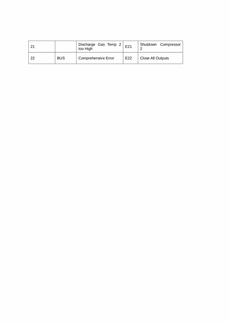
21 Discharge Gas Temp 2 too High E21 Shutdown Compressor
2
22 BUS Comprehensive Error E22 Close All Outputs