Installation ZUGPP2 and ZUGSS2 Trim Kit Instructions
8
ZUGPP2 and ZUGSS2 Trim Kit Stainless Steel Unified Grille Panel Installation Instructions Tools and materials Required: • #1 and #2 Phillips screwdrivers • Safety glasses • Gloves to protect against sharp edges Parts List: A. Stainless steel unified grille panel B. Foam spacer pads C. 10 Black #8-32 x 3/8” screws This kit provides for the installation of a stainless steel unified grille panel. The panel will span the combined width of a side-by-side installation. Completion Time: Allow approximately 2 hours to install this kit. IMPORTANT: 2 People are required to install this kit. Disconnect power before you begin. THE INSTALLATION SPACE • The installation space must be 71-1/2" wide. • The water and electrical locations for each product must be located as shown. • A separate 115V, 60Hz., 15 or 20 amp power supply is recommended for each product. A B C Note: Additional cutout width may be required when side panels are used. Add side panel thickness to the finished cutout to calculate rough-in width. 71-1/2" Finished Width Wall View Electrical 24-3/16" 9" Electrical Area 24" Minimum Cutout Depth 75-1/2" From Floor to Bottom of Electrical Area 84-1/2" max. 83-1/2" min. Finished Opening 3-1/2" 3-1/2" 3-1/2" 3-1/2" 3-1/2" 3-1/2" 3-1/2" 3-1/2" 3-1/2" 3-1/2" 5" 5" 5" 5" Cold Water Supply Cold Water Supply 9" 5-1/2" 5-1/2" 2-5/16"
Transcript of Installation ZUGPP2 and ZUGSS2 Trim Kit Instructions

ZUGPP2 and ZUGSS2 Trim KitStainless SteelUnified Grille Panel
InstallationInstructions
Tools and materials Required:• #1 and #2 Phillips screwdrivers
• Safety glasses
• Gloves to protect against sharp edges
Parts List:A. Stainless steel unified grille panel
B. Foam spacer pads
C. 10 Black #8-32 x 3/8” screws
This kit provides for the installation of a stainless steel unifiedgrille panel. The panel will span the combined width of a side-by-side installation.
Completion Time: Allow approximately 2 hours to install this kit.IMPORTANT: 2 People are required to install this kit.Disconnect power before you begin.
THE INSTALLATION SPACE• The installation space must be 71-1/2" wide.
• The water and electrical locations for each product must be located as shown.
• A separate 115V, 60Hz., 15 or 20 amp power supply is recommended for each product.
A
B
C
Note: Additional cutout width may be required whenside panels are used. Add side panel thickness to thefinished cutout to calculate rough-in width.
71-1/2" Finished Width
Wall ViewElectrical 24-3/16"
9"Electrical
Area
24" MinimumCutout Depth
75-1/2" From Floor to Bottom
of Electrical Area
84-1/2" max. 83-1/2" min.
Finished Opening
3-1/2"3-1/2"
3-1/2" 3-1/2"3-1/2"
3-1/2"
3-1/2"3-1/2"3-1/2"3-1/2"
5" 5" 5" 5"
Cold Water Supply
Cold Water Supply
9"
5-1/2"5-1/2"
2-5/16"

2
STEP 2 INSTALL ANTI-TIP BRACKETBOTTOM FREEZER MODELS ONLY
WARNING: ANTI-TIP PRECAUTIONSThese refrigerators are top-heavy and must be secured to prevent the possibility of tipping forward.
ATTENTION : PRECAUTIONS CONTRE LES BASCULEMENTSLe réfrigérateur est beaucoup plus lourd en haut et il faut le maintenir en place pour éviter la possibilité de son basculement vers l’avant.
• Cut a 2"x4" block 71" long. Secure the 2"x4" to the 4mounting brackets provided using #12 or #14 woodscrews.
• Secure the brackets with wood block to the back wall so that it is 84" (or your installation height) from the finished floor. Use #12 or #14 wood screws. See illustration.
• Screws must penetrate at least one inch into verticalwall studs.
• Gently push refrigerator into the opening with handsagainst front corners.
Note: When the refrigerators are installed under a soffit , or if there is not enough height for this method of security,brackets cannot be used. Proceed to “Level theRefrigerator” and to “Secure side trim to cabinetry.” The refrigerators must be secured to prevent tipping.
STEP 1 INSTALL FOAM SPACER PADS
CAUTION: Handle parts with care to avoid scratching.
PRUDENCE : Manipulez les pièces soigneusement pour éviter de les rayer.
Apply the supplied foam spacer pads (B) to the mating side of one product as shown.
(Bottom–Mount and All Refrigerator/All Freezer Models)
Foam Spacer Pads
BracketsRequired
Block
HeightFrom Floorto Bottomof Wood
Block
SoffitBrackets
Not RequiredBeneath a Soffit
Side View
2 x 4 Cut to 35" Length
Mounting Bracket
InstallationHeight
From Floor
Wood Screws Mounted intoVertical Wood Studs

3
STEP 2 INSTALL ANTI-TIP BRACKETALL REFRIGERATOR, ALL FREEZER “X” MODELS ONLY
WARNING: ANTI-TIP PRECAUTIONSThe unit is top-heavy and must be secured to preventthe possibility of tipping forward.
ATTENTION : PRECAUTIONS CONTRE LES BASCULEMENTSL’appareil ménager est beaucoup plus lourd en haut et il faut le maintenir en place pour éviter la possibilitéde son basculement vers l’avant.
• The kit supplied with the unit contains 3 (2 required, 1 extra) lag bolts and 5 (4 required, 1 extra) toggleswith bolts. The wall bracket will be attached to the wall in 4 places.
• Measure the opening where the unit is to be installed.Mark the center with a vertical line.
• Measure up 81-1/2" from the floor. Mark this point on the wall.
• Using a level, draw a horizontal line on the wall at this height.
• Locate at least 2 studs on the back wall. Mark thesepoints on the horizontal line.
• Place the bottom of the wall bracket with tabs on the horizontal line. Align the center notch on the bracket with the center line on the wall.
• The anti-tip wall bracket has a series of holes. Select 2 holes that match with the located studs. Make sure the holes selected are on the center of the studs. Mark the wall at these points.
• Mark an additional hole at each end of the bracket. If one of the studs is closer to the end of the bracket,mark an additional hole towards the center of the bracket.
• Drill 1/2" holes into the wallboard at the locationsmarked for the toggles to be mounted (not the studmarkings).
• Drill 3/16" holes into wooden studs where marked. If steel stud construction, drill 1/2" holes into the studswhere marked. You will use 2 toggles with the metalstuds.
Line on Wall
Center
81-1/2"
To Floor
CenterWall Bracket
Line on Wall
Wall Studs
Two AdditionalHole Locations atEnds of Brackets
4
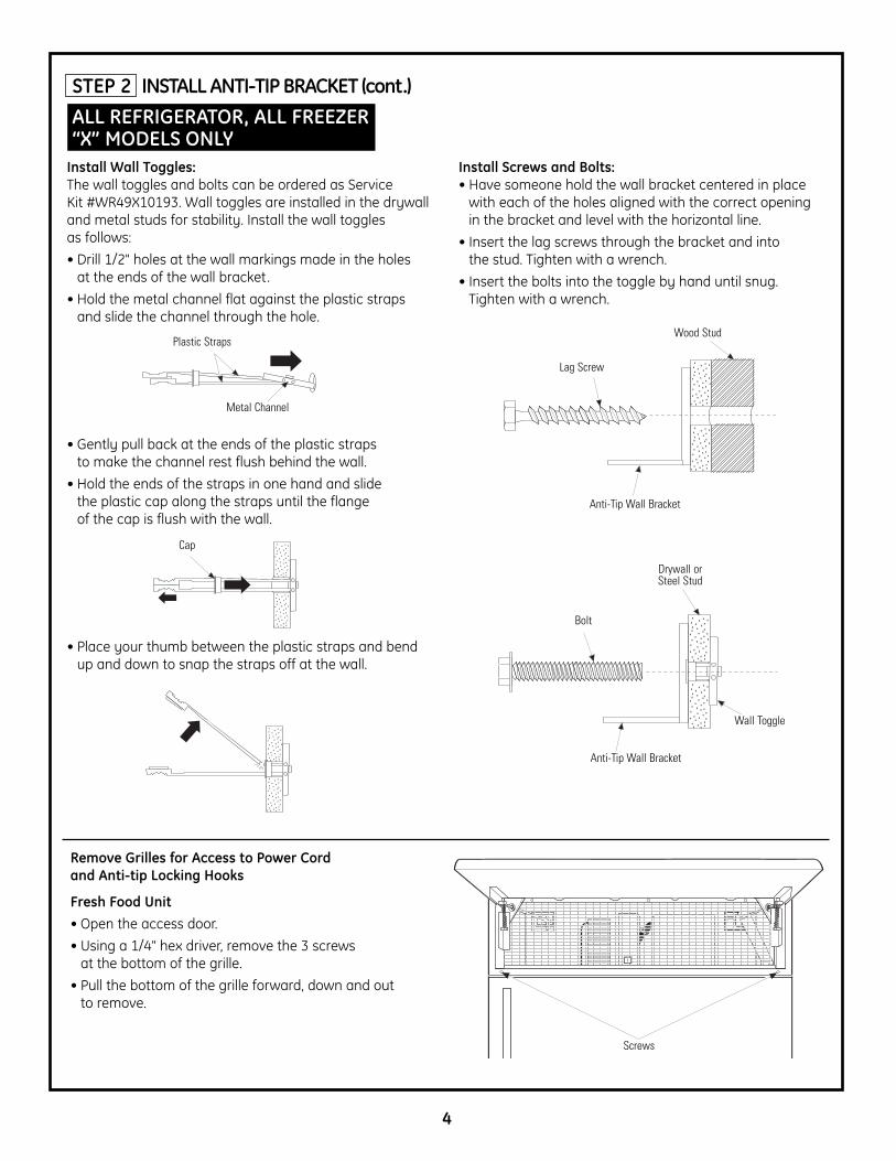
Install Screws and Bolts:• Have someone hold the wall bracket centered in place
with each of the holes aligned with the correct openingin the bracket and level with the horizontal line.
• Insert the lag screws through the bracket and into the stud. Tighten with a wrench.
• Insert the bolts into the toggle by hand until snug.Tighten with a wrench.
STEP 2 INSTALL ANTI-TIP BRACKET (cont.)ALL REFRIGERATOR, ALL FREEZER “X” MODELS ONLY
Install Wall Toggles:The wall toggles and bolts can be ordered as Service Kit #WR49X10193. Wall toggles are installed in the drywall and metal studs for stability. Install the wall toggles as follows:
• Drill 1/2" holes at the wall markings made in the holes at the ends of the wall bracket.
• Hold the metal channel flat against the plastic strapsand slide the channel through the hole.
• Gently pull back at the ends of the plastic straps to make the channel rest flush behind the wall.
• Hold the ends of the straps in one hand and slide the plastic cap along the straps until the flange of the cap is flush with the wall.
• Place your thumb between the plastic straps and bendup and down to snap the straps off at the wall.
Remove Grilles for Access to Power Cord and Anti-tip Locking Hooks
Fresh Food Unit• Open the access door.
• Using a 1/4" hex driver, remove the 3 screws at the bottom of the grille.
• Pull the bottom of the grille forward, down and out to remove.
Metal Channel
Plastic Straps
Cap
Lag Screw
Wood Stud
Anti-Tip Wall Bracket
Bolt
Drywall orSteel Stud
Wall Toggle
Screws
Anti-Tip Wall Bracket

5
STEP 2 INSTALL ANTI-TIP BRACKET (cont.)ALL REFRIGERATOR, ALL FREEZER “X” MODELS ONLY
Remove Grilles for Access to Power Cord and Anti-tipLocking Hooks
Power CordLocate the power cord inside the left cavity. If it has notbeen adjusted so the plug is easily accessible, do so now.
Freezer Unit• Open the access door.
• Using a 1/4" hex driver, remove the 2 screws at the bottom of the grille on the right.
• Pull the bottom of the grille forward, down and out to remove.
• Using a 1/4" hex driver, remove the screw on the leftside of the grille.
• The grille is aluminum and will bend easily. Gently pullforward on the left side of the grille to open for access.This grille will not be completely removed.
STEP 3 LEVEL REFRIGERATORSBoth products MUST BE LEVEL AND PLUMB with eachother and with adjacent cabinetry on each side.
• Adjust carefully. Both models have 4-point leveling.The front is supported by leveling legs, the rear is supported by wheels. Both are accessible from the front of the refrigerator.
• For bottom-mount refrigerator models only, turn the 7/16" hex nut located above the front wheels to raise or lower the back of the refrigerator until it just barely touches the 2 x 4 blocks.
• For All Refrigerator/All Freezer models, turn the 7/16”hex nut located above the front wheels to raise or lower the unit to close the gap at the top of the cabinets.
• For front leveling, use a 1-1/4" open-ended wrench to turn the leveling legs.
The inside case trims must be aligned without gaps at the top and bottom.
“L” Bolt
Power Cord Location
Left Grille Open
Screws
Hex Nut AdjustsRear Wheels
Leveling Leg

6
STEP 4 SECURE UNIT TO WALLALL REFRIGERATOR, ALL FREEZER “X” MODELS ONLY
• The “L” rods can be found in the upper left and rightcorners of the unit in the access compartment. Look through the access compartment to make sure the rods line up with the anti-tip bracket.
• There are 2 washers and a hair pin cotter per rod.Remove the washers and hair pin cotter from the endof the rod.
• Rotate and move the “L” rod into the slot in the anti-tipbracket tab. Once it is in the slot, rotate the “L” rod so the hook portion is pointing down. The holes at the front end of the rod should be in a vertical position. Do this to both sides.
• Pull out on the end of the rod to take make sure it is secure in the bracket.
• Locate the hole on the rod that is closest to the unit. A hair pin cotter will be put through this hole to securethe rod. If this hole appears to be too far away for a snug fit against the unit, add the washers one at a time until the pin will fit tightly into the hole.
• Align the straight section of the pin with the hole fromthe underside of the rod. Push the pin up until it snapsinto position. Pliers may be used. NOTE: The hair pincotter must be vertical when this step is completed toensure the “L” rod is engaged in the bracket.
• Check the rod for tightness by pulling forward. If the rod moves, remove the hair pin cotter and placeanother washer on the rod. Reinsert the pin.
• Bend the left grille back into place (freezer only) andreplace the screws.
• Replace the flat grille panel by sliding it under theflange at the top of the access compartment andpushing the grille back into place. Replace screws.
“L” Rod Pointing DownEngaged in Bracket
“L” Rod
Washer
Hair Pin CotterIs Vertical
Wall Bracket
“L” Rod
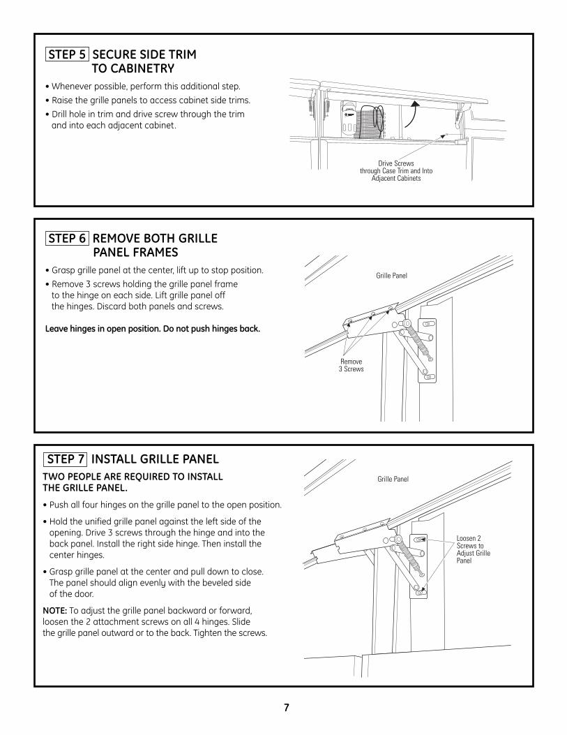
STEP 7 INSTALL GRILLE PANELTWO PEOPLE ARE REQUIRED TO INSTALL THE GRILLE PANEL.
• Push all four hinges on the grille panel to the open position.
• Hold the unified grille panel against the left side of the opening. Drive 3 screws through the hinge and into the back panel. Install the right side hinge. Then install the center hinges.
• Grasp grille panel at the center and pull down to close. The panel should align evenly with the beveled side of the door.
NOTE: To adjust the grille panel backward or forward, loosen the 2 attachment screws on all 4 hinges. Slide the grille panel outward or to the back. Tighten the screws.
Loosen 2Screws toAdjust GrillePanel
7
STEP 6 REMOVE BOTH GRILLE PANEL FRAMES
• Grasp grille panel at the center, lift up to stop position.
• Remove 3 screws holding the grille panel frame to the hinge on each side. Lift grille panel off the hinges. Discard both panels and screws.
Leave hinges in open position. Do not push hinges back.
STEP 5 SECURE SIDE TRIMTO CABINETRY
• Whenever possible, perform this additional step.
• Raise the grille panels to access cabinet side trims.
• Drill hole in trim and drive screw through the trim and into each adjacent cabinet.
Drive Screwsthrough Case Trim and Into
Adjacent Cabinets
Remove3 Screws
Grille Panel
Grille Panel

8
31-46526-2224D1889P01109-08 JR
NOTE: While performing installations described in this book,safety glasses or goggles should be worn.
NOTE: Product improvement is a continuing endeavor at General Electric. Therefore, materials, appearance and specifications are subject to change without notice.
GE Consumer & IndustrialAppliances General Electric Company Louisville, KY 40225ge.com
NOTA: Mientras efectúa las instalaciones descriptas en este libro, deben utilizarse gafas o lentes de seguridad.
NOTA: La mejora de los productos es un esfuerzo continuopara General Electric. Por lo tanto, los materiales, la apariencia y las especificaciones pueden sufrir cambios sin previo aviso.