INSTALLATION & USER’S GUIDE - RevZilla.com · 2017-05-27 · 7. Install the OEM gasket. 8....
47
©2017 Rekluse Motor Sports Rekluse Motor Sports, Inc. [email protected] INSTALLATION & USER’S GUIDE RadiusCX Clutch For KTM/Husqvarna CSS clutches Doc ID: 191-7902A Revision: 050217
Transcript of INSTALLATION & USER’S GUIDE - RevZilla.com · 2017-05-27 · 7. Install the OEM gasket. 8....
©2017 Rekluse Motor Sports
Rekluse Motor Sports, Inc. [email protected]
INSTALLATION & USER’S GUIDE
RadiusCX Clutch For KTM/Husqvarna CSS clutches
Doc ID: 191-7902A Revision: 050217

Pg. 2 Doc ID: 191-7902A Doc Rev: 050217
TABLE OF CONTENTS OVERVIEW ............................................................................................... 3
INSTALLATION TIPS ................................................................................ 3
TOOLS NEEDED ...................................................................................... 4
INCLUDED PARTS ................................................................................... 5
DISASSEMBLE THE CLUTCH ................................................................. 6
INSTALL THE HUB ................................................................................... 8
CLUTCH PACK INSTALLATION ............................................................... 9
PRESSURE PLATE INSTALLATION ...................................................... 13
SLAVE CYLINDER INSTILLATION ......................................................... 16
Step 1: Bleed the new slave cylinder ......................................... 16
Step 2: Replace OEM slave cylinder ......................................... 19
BLEED THE CLUTCH LINE .................................................................... 23
SET THE INSTALLED GAP AND VERIFY BY CHECKING FREE PLAY GAIN ........................................................................................................ 26
Step 1: Find the starting point .................................................... 27
Step 2: Learn how to check Free Play Gain .............................. 28
Two Ways to Check for Free Play Gain ..................................... 30
The Rubber Band Method ......................................................... 30
The Hand Method ...................................................................... 33
Step 3: Break-in the new clutch ................................................. 35
Step 4: Adjust the installed gap and Recheck Free Play Gain ... 37
FREE PLAY GAIN ADJUSTMENTS ....................................................... 39
MAINTENANCE ...................................................................................... 40
Disk inspection examples .......................................................... 42
TROUBLESHOOTING ............................................................................ 43
Performance issues ................................................................... 43
Clutch noise ............................................................................... 43
EXP TUNING OPTIONS ......................................................................... 43
Changing the springs ................................................................. 44
Configuration chart .................................................................... 46
BUMP-STARTING ................................................................................... 46
NEED ADDITIONAL HELP? .................................................................... 47

Doc ID: 191-7902A Doc Rev: 050217
Pg. 3
This kit replaces many of the OEM clutch parts while reusing some of the OEM clutch parts. The following is a summary of what is replaced and what is reused: • All OEM steel drive plates will be replaced with Rekluse TEC
drive plates • All OEM friction disks will be replaced with Rekluse TorqDrive®
disks • All 6 of the OEM drive pins will be reinstalled • The OEM clutch cover O-ring will be reused
• Read the safety information sheet included with your kit.
• Watch the “RadiusCX Auto Clutch Installation Video” by visiting www.rekluse.com/support/videos.
• Protect eyes and skin – wear safety glasses and thin disposable work gloves.
• Read this entire document before performing any steps. • Lay the motorcycle on its left side when replacing the clutch.
This makes the clutch work easier and eliminates the need to drain the oil.
• Use an air or electric impact wrench to remove the center clutch nut. If one is not available, you can place the bike in top gear and hold the rear brake while loosening the center clutch nut with a socket and breaker bar.
• Channel-lock pliers work best to bend the tabs of the washer up over the center clutch nut.
• Use clean, quality JASO MA or JASO MA2 certified transmission oil for best performance.
OVERVIEW
INSTALLATION TIPS

Pg. 4 Doc ID: 191-7902A Doc Rev: 050217
• Bikes with taller gearing or modified engines with increased horsepower may require heavier wedges. These can be purchased separately from Rekluse.
4 mm Allen Wrench 5 mm Allen Wrench 8 mm Socket 27 mm Socket
Torque Wrench Channel-lock Pliers Fluid Catch Container No Tools Required
Recommended Clutch Fluid Calipers
TOOLS NEEDED
4 mm 5 mm 8 mm 27 mm

Doc ID: 191-7902A Doc Rev: 050217
Pg. 5
Visit www.rekluse.com/support for a full parts fiche illustration and part numbers.
INCLUDED PARTS
Item Description Qty. 5 Pressure Plate 1
13 EXP Bases 2 16 Steel Lining Plate 1 23 Clutch Cover 1 27 Center Hub 1 30 Lock Tab Washer 1 51 Fastener - 1/4-Turn Pin 6
60.X
EXP Adjustment Spring (extra adjustment springs are included, see last page for EXP tuning options) 6
63 TEC Steel Drive Plate 9 69 TorqDrive® Friction 8 85 Wedge Assembly 6
86 Adjustable Slave Cylinder Assembly (bleed syringe included) 1
88 Spring Kit 1

Pg. 6 Doc ID: 191-7902A Doc Rev: 050217
1. Turn the fuel petcock to “OFF” if applicable.
2. Lay the bike on its left side. Catch any fuel that might drain
in a suitable container.
3. Use an 8 mm socket to remove the clutch cover.
DISASSEMBLE THE CLUTCH
8 mm

Doc ID: 191-7902A Doc Rev: 050217
Pg. 7
4. Use an 8 mm socket to remove the following OEM parts. See following picture for reference.
• 6 pressure plate bolts and springs
• Pressure plate • Throw-out bearing and
washer
• Center clutch nut and washer • 12 drive pins • Clutch pack • Center clutch hub
Be careful that the drive pins do not fall into the engine while disassembling.
8 mm

Pg. 8 Doc ID: 191-7902A Doc Rev: 050217
5. Use a hammer and large screwdriver to bend down the tabs of the washer tab, then remove the center clutch nut and washer with an impact wrench or breaker bar, and a 27 mm socket.
1. Install the new Rekluse center clutch hub into the bike. Check to make sure the thrust washer is still on the main shaft before you install the hub.
2. Reinstall the Rekluse tab washer and OEM center clutch nut. 3. Using the 27 mm socket and torque wrench,
torque the center clutch nut to OEM specification.
INSTALL THE HUB
27 mm
27 mm Torque Wrench
No Tools Required

Doc ID: 191-7902A Doc Rev: 050217
Pg. 9
4. Bend up both tabs of the tab washer using channel-
lock pliers.
5. Seat the 6 OEM drive pins into the Rekluse outer hub.
Each clutch pack comes with a set of steel plates and a set of friction disks. The specifics of the clutch pack depend on the bike. The height of the assembled clutch pack and specific information about the clutch pack can be found on the Setup Sheet.
CLUTCH PACK INSTALLATION
Channel-lock Pliers

Pg. 10 Doc ID: 191-7902A Doc Rev: 050217
1. Soak the friction disks and EXP disk in new oil for at least 5 minutes.
2. Install a steel TEC drive plate by first aligning the drive pin
notches in the plate with the drive pins on the hub.
3. Place the steel plates in the orientation shown with the shark fin
notches facing to the right. All drive plates will follow this orientation.
Oil
Drive pins
No Tools Required
Shark fin notches
Drive pin notches

Doc ID: 191-7902A Doc Rev: 050217
Pg. 11
Proper orientation of the drive plates is critical for optimal clutch performance. If you install them backwards, the clutch will still function but will lack proper modulation performance.
4. Add a fiction disk on top of the steel drive plate. Some friction
disks are marked with a small colored dot. This mark is used for processing and can be ignored.
5. Continue alternating the steel drive plates with the friction disks
for the entire Rekluse clutch pack.
*Refer to the Setup Sheet included with the clutch kit for the “Clutch Pack Height” specifications.

Pg. 12 Doc ID: 191-7902A Doc Rev: 050217
6. Install the EXP disk on top of the last steel plate. Make sure that the EXP disk is seated in the same slots as the clutch pack.
Some OEM basket have “half slots” at the top of the basket tangs. Rekluse products require that the entire clutch pack, including the EXP disk, be installed into the MAIN (deeper) basket slots.
7. Reinstall the OEM throw-out.

Doc ID: 191-7902A Doc Rev: 050217
Pg. 13
1. Add a light film of oil between the lining plate and pressure plate. This will help the plates stick together for ease of installation.
2. Install the supplied lining plate onto the Rekluse pressure plate by lining up the index tabs into the slots.
3. Install the pressure plate subassembly.
PRESSURE PLATE INSTALLATION
Oil
No Tools Required

Pg. 14 Doc ID: 191-7902A Doc Rev: 050217
4. Place the pressure plate springs into the assembled clutch, then insert the screw sleeves into the springs.
5. Insert the pressure plate bolts into the screw sleeves.
Do not reuse the OEM springs, or clutch cover interference will occur! 6. Using a torque wrench, tighten the pressure plate
bolts to 9 ft-lb (12-N-m). Torque Wrench

Doc ID: 191-7902A Doc Rev: 050217
Pg. 15
7. Install the OEM gasket.
8. Install the Rekluse clutch cover by lightly tightening the cover bolts in a star pattern. Tighten bolts in small increments before torquing the cover bolts to OEM specifications. If your bike has an oil plug, transfer the OEM oil plug to the new Rekluse clutch cover.
Torque Wrench

Pg. 16 Doc ID: 191-7902A Doc Rev: 050217
Installing the new Rekluse slave cylinder takes several steps. Please read the entire section before beginning the process to ensure you have the right equipment and clutch fluid needed for the replacement. Rekluse recommends wearing gloves and safety glasses for the install.
During the bleed and assembly, note that there is a small ball bearing installed in the slave piston with a small amount of grease. When installing the Rekluse slave cylinder, make sure the ball is in place and has not come loose.
Step 1: Bleed the new slave cylinder This step prepares the new slave cylinder for installation. Bleed the cylinder on a workbench or an area away from the bike.
1. Using a 4 mm Allen wrench, turn the adjuster screw counterclockwise so that the top O-ring is visible under the adjuster screw.
SLAVE CYLINDER INSTILLATION
4 mm

Doc ID: 191-7902A Doc Rev: 050217
Pg. 17
2. Use your thumbs to compress the piston until it bottoms out, then release it.
3. Pour the recommended clutch fluid into the slave cylinder port.
Be sure to use the correct clutch fluid. Check the cap of the clutch master cylinder to determine which clutch fluid to use. Failure to use the correct fluid will result in seal damage and/or failure.
4. Use a 4 mm Allen wrench to turn the adjuster screw
clockwise until it bottoms out and the O-ring in no longer visible. Keep the fluid topped off as you go.
4 mm

Pg. 18 Doc ID: 191-7902A Doc Rev: 050217
5. Use the wrench to turn the adjuster screw counterclockwise back to the initial position, with the top O-ring visible. Keep the fluid topped off as you go.
6. Use your thumbs to compress the piston again until it bottoms
out while looking for air bubbles.
When compressing the piston, fluid can shoot out from the slave cylinder port. Be sure to wear eye protection.
7. Repeat steps 3 - 6 until there are no air bubbles coming out in
the fluid when the piston is compressed.
8. When the bleeding is complete, turn the adjuster screw counterclockwise so that the top O-ring is visible.
9. Compress the piston until it bottoms out, and top off with fluid.

Doc ID: 191-7902A Doc Rev: 050217
Pg. 19
10. Check that the ball bearing is still in place. Stand the Rekluse slave cylinder in an upright position (so that the fluid does not spill) until it is needed in the next step.
Step 2: Replace OEM slave cylinder In this step, the OEM slave cylinder is replaced with the Rekluse slave cylinder. Work quickly when performing the following steps. This method retains the fluid inside the line, and makes the final bleeding step easier. 1. Stand the bike up and lean it on its kickstand, or place it on a
suitable bike stand.
If you are installing on a Freeride bike model, see the Slave Cylinder Appendix sheet for proper install instructions.

Pg. 20 Doc ID: 191-7902A Doc Rev: 050217
2. On the left side of the bike, while leaving the OEM slave cylinder intact on the engine, use a wrench to remove the banjo bleeder bolt from the OEM Slave cylinder.
3. Separate the OEM slave cylinder from the clutch fluid line. 4. Remove and discard the 2 OEM crush washers.
5. Attach the clutch fluid line to the Rekluse slave cylinder using the
OEM banjo bleeder bolt and the 2 crush washers from Rekluse. Make sure the clutch fluid line is between the 2 crush washers.

Doc ID: 191-7902A Doc Rev: 050217
Pg. 21
2016 FC450 and 2017+ FC450/501 OWNERS: Use the supplied banjo bleeder bolt in place of the OEM banjo bolt. Insert bleeder bolt into Rekluse slave cylinder in the same orientation as it was in the OEM slave cylinder
6. Tighten the banjo bolt with your hand until snug. (You will torque
it to spec once installed on the bike.) 7. With the clutch fluid line attached to the Rekluse slave cylinder,
remove the OEM slave cylinder from the engine. Keep the OEM bolts for reuse.
8. Mount the Rekluse slave cylinder to the engine using the OEM
bolts.
The Rekluse slave cylinder comes preassembled in the kit. If the parts are separated, assemble them in the following order: Rekluse slave cylinder, O-ring (the one supplied or OEM), then the supplied paper gasket. Not all slave cylinders come with a gasket. If not supplied, use the OEM gasket.

Pg. 22 Doc ID: 191-7902A Doc Rev: 050217
If you need to install the case sealing O-ring seal (OEM or Rekluse supplied), make sure it is seated against the slave cylinder flange.
Some models have a piston diaphragm seal. DO NOT reuse them if OEM equipped. The Rekluse slave cylinder does not require a diaphragm seal.
9. Torque the banjo bolt to OEM specification.

Doc ID: 191-7902A Doc Rev: 050217
Pg. 23
Optional: If you purchased the Rekluse Slave Guard accessory, install it now using the specific instructions included with the slave guard kit.
1. Attach one end of the supplied bleed tube to the banjo bolt port, then loop the opposite end into a suitable catch bottle.
2. On the handlebar, remove the cap and bladder from the clutch
master cylinder. Adjust the reservoir so it is level with the ground.
BLEED THE CLUTCH LINE

Pg. 24 Doc ID: 191-7902A Doc Rev: 050217
3. Top off the master cylinder with the recommended clutch fluid until it is 75% full.
4. Pump the clutch lever 3 to 5 times, then hold it against the
handlebar/grip.
5. While still holding the clutch lever in, use a wrench to open the
bleed port. Air and fluid should flow from the bleed tube.
6. Before releasing the clutch lever, tighten the bleed port when the
pressure is released from the bleed tube.

Doc ID: 191-7902A Doc Rev: 050217
Pg. 25
7. Slowly release the clutch lever and check the fluid level in the clutch master cylinder. Top off if necessary.
8. Repeat steps 4 - 7 until air no longer comes out of the bleed tube
and the clutch feels normal. 9. Check that the clutch master cylinder is 75% full, then replace
the cap and bladder.
10. Remove the bleed tube from the bleed bolt and remove the bottle.
Pg. 26 Doc ID: 191-7902A Doc Rev: 050217
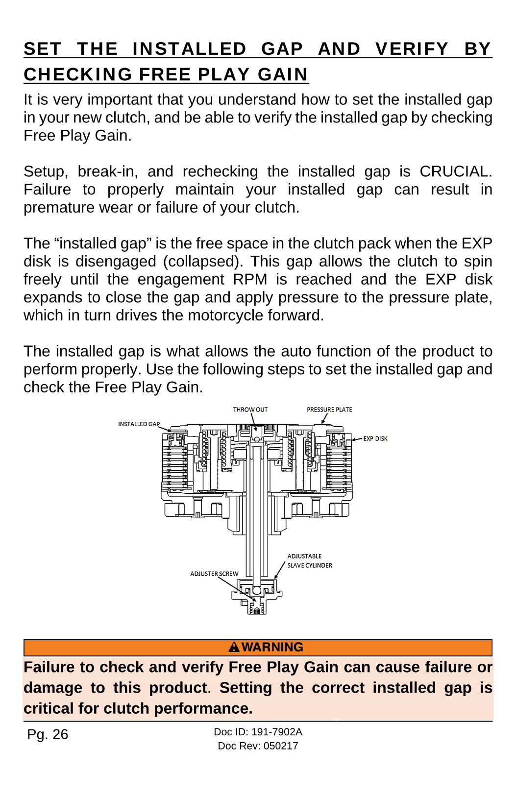
It is very important that you understand how to set the installed gap in your new clutch, and be able to verify the installed gap by checking Free Play Gain. Setup, break-in, and rechecking the installed gap is CRUCIAL. Failure to properly maintain your installed gap can result in premature wear or failure of your clutch. The “installed gap” is the free space in the clutch pack when the EXP disk is disengaged (collapsed). This gap allows the clutch to spin freely until the engagement RPM is reached and the EXP disk expands to close the gap and apply pressure to the pressure plate, which in turn drives the motorcycle forward. The installed gap is what allows the auto function of the product to perform properly. Use the following steps to set the installed gap and check the Free Play Gain.
Failure to check and verify Free Play Gain can cause failure or damage to this product. Setting the correct installed gap is critical for clutch performance.
SET THE INSTALLED GAP AND VERIFY BY CHECKING FREE PLAY GAIN

Doc ID: 191-7902A Doc Rev: 050217
Pg. 27
Setting the installed gap and checking Free Play Gain is a 4-step process. It is important to follow each step to ensure that your new clutch functions as designed. Step 1: Find the starting point
a) With the bike standing up, locate the adjuster screw in the center of the adjustable slave cylinder.
b) With the O-ring showing, use a 4 mm Allen wrench to turn the adjuster screw clockwise until it stops under light pressure. This is your “starting point.”
The resistance you feel is where the throw-out begins to lift the pressure plate. Finding the right starting point may take a few tries, but you will feel a noticeable change in turning effort once you reach that point. Stop when you feel the pressure increase. The “starting point” will change as the clutch pack wears over time.
c) Once you have found the starting point, note the position of the
Allen wrench using the tick marks on the slave cylinder housing and the small etch mark located on the screw. You will begin here to adjust the installed gap.

Pg. 28 Doc ID: 191-7902A Doc Rev: 050217
d) Use a 4 mm Allen wrench to turn the adjuster screw clockwise
1 full turn + 2 tick marks from your starting point. This may NOT be your final setting, but it is a beginning adjustment for finding the correct setting.
e) Continue with Step 2 to check for Free Play Gain.
Do not ride your bike without the adjusting the installed gap. You will not be able to disengage the clutch until you set the installed gap.
Step 2: Learn how to check Free Play Gain Feeling Free Play Gain with the beginning adjustment to the slave cylinder aids in learning to recognize Free Play Gain. If you are familiar with Free Play Gain, you can skip to Step 3 -“ Break-in the new clutch.” If Free Play Gain is new to you, follow the instructions below to help you learn this important step. You can also view the video entitled “How to Check Free Play Gain” on our website at www.rekluse.com/support/videos. Free Play Gain is different from the “normal” free play you are used to with your stock clutch. With the Rekluse auto clutch, Free Play Gain is the result of the EXP disk expanding and lifting the pressure plate to engage the clutch. Free Play Gain happens when the engine’s RPM increases from idle to above approximately 5,000 RPM and the EXP closes the installed
Use the tick marks on the cylinder and the etch mark on the screw to remember the starting point for adjusting the gap.

Doc ID: 191-7902A Doc Rev: 050217
Pg. 29
gap. The amount of Free Play Gain you feel in the lever corresponds to the amount the pressure plate has been lifted by the EXP disk expansion. Checking Free Play Gain allows you to externally monitor the installed gap so you can know when to make an adjustment if the installed gap is too large or too small. The correct installed gap is verified by observing and feeling the increased free play movement in the clutch lever. This extra movement is called “Free Play Gain.”
If there is too much Free Play Gain, the installed gap is too small. The bike may drag and stall because it has difficulty disengaging the clutch. It may also be difficult to shift. Too much Free Play Gain will not hurt the clutch, but it will negatively affect clutch performance. With too little or no Free Play Gain, the installed gap is too large. This means when the EXP is fully expanded it does not lift the pressure plate. The clutch may slip and make the bike seem like it is losing power. The bike may not move forward even though the engine RPM increases as if the clutch lever is slightly pulled. Too little Free Play Gain will cause the clutch system to burn up. Optimal Free Play Gain yields 1/8” (3 mm) of clutch lever movement, measured at the ball end of the lever. This measurement at the lever correlates to achieving the ideal installed gap.

Pg. 30 Doc ID: 191-7902A Doc Rev: 050217
Two Ways to Check for Free Play Gain The following steps explain 2 ways to check Free Play Gain. One way uses the rubber band Rekluse includes in the clutch kit, and one uses your hand. You can use either method to check for Free Play Gain.
Rekluse recommends that you begin with the rubber band method first to check for Free Play Gain and then learn the hand method. The rubber band will help you learn how to recognize Free Play Gain until you are comfortable with the hand method. Learning to check Free Play Gain by hand effectively and comfortably can make it easy to check Free Play Gain every time you ride.
The Rubber Band Method Use the rubber band method for the initial set up. It can also be used before each ride until you feel comfortable checking the Free Play Gain using the hand method.
BEFORE YOU BEGIN, verify that the bike is in NEUTRAL before checking Free Play Gain. Failure to do so may result in the bike lurching forward, and loss of control and/or injury may result. A Rekluse auto-clutch can make your motorcycle appear to be in neutral when in gear, even when the engine is running and clutch lever released. Motorcycles equipped with a Rekluse auto-clutch can move suddenly and unexpectedly and cause riders to lose control. To avoid death, serious injury, and/or property damage, always sit on the motorcycle to start it.
a) Before you begin, place the bike in NEUTRAL, start the
engine and let it warm up for 2-3 minutes to idle down and warm the engine oil.

Doc ID: 191-7902A Doc Rev: 050217
Pg. 31
b) Stretch the included rubber band between your thumbs, then place the top end of the rubber band on the outer end of the left handlebar grip.
c) While holding the top end of the rubber band against the
handlebar, stretch the band downward, then loop it through itself.

Pg. 32 Doc ID: 191-7902A Doc Rev: 050217
d) Pull the band through the loop, then attach it to the outside end of the clutch lever. This will take up the initial free play (slack) and put the lever in a position to detect the Free Play Gain.
e) While still in NEUTRAL, quickly rev the engine between 5,000-
7,000 RPM (1/2 to ¾ throttle), then let it return to idle. Notice the movement in the clutch lever when the engine is revved. This is your Free Play Gain.
It is very important the motor returns to idle before revving the engine again or Free Play Gain will not be correct.

Doc ID: 191-7902A Doc Rev: 050217
Pg. 33
f) When the bike returns to idle, rest your hand across the clutch lever. Rev the engine again to 5,000-7,000 RPM so you can observe the movement while feeling for Free Play Gain with your hand.
The Hand Method Use the hand method to check Free Play Gain before the start of every ride for optimum performance and longevity of your new clutch.
BEFORE YOU BEGIN, verify that the bike is in NEUTRAL before checking Free Play Gain. Failure to do so may result in the bike lurching forward, and loss of control and/or injury may result. A Rekluse auto-clutch can make your motorcycle appear to be in neutral when in gear, even when the engine is running and clutch lever released. Motorcycles equipped with a Rekluse auto-clutch can move suddenly and unexpectedly and cause riders to lose control. To avoid death, serious injury, and/or property damage, always sit on the motorcycle to start it.
a) Before you begin, place the bike in NEUTRAL, start the engine
and let it warm up for 2-3 minutes to idle down and warm up the engine oil.

Pg. 34 Doc ID: 191-7902A Doc Rev: 050217
b) With the bike at idle, apply enough pressure to the clutch lever to take up the initial free play (slack) in the clutch lever.
c) While still in NEUTRAL, continue to apply light pressure and
quickly rev the engine between 5,000-7,000 RPM (1/2 to ¾ throttle), then let it return to idle. Notice the movement in the clutch lever when the engine is revved. This is your Free Play Gain.
d) When the bike returns to idle, rev the engine between 5,000-
7,000 RPM a second time to feel the Free Play Gain again. e) Continue with Step 3 to break-in the new clutch.

Doc ID: 191-7902A Doc Rev: 050217
Pg. 35
The lever may move more than 1/8” (3 mm) toward the handle when the engine is revved because there is too much Free Play Gain (movement of the clutch lever). This changes as you adjust the installed gap. Step 3: Break-in the new clutch Once you install your new clutch, it is important to break it in. A series of roll-on starts are used to break in the clutch. Follow these procedures for breaking in your clutch and any time new friction disks, EXP bases, Teflon pads, or wedges are installed.
Failure to follow the break-in procedure and oil screen inspection process could cause motor oil delivery failure which can result in motor failure, serious injury, or death. Break-in Procedure Number of times
Rev Cycles:
1. Place the bike in NEUTRAL. 2. With your hand off the clutch lever, rev
the engine 10 times, being sure to let it return to idle between each rev cycle.
10 rev cycles

Pg. 36 Doc ID: 191-7902A Doc Rev: 050217
3. With the engine still running, pull in the clutch lever, then click the bike into 1st gear. Slowly release the clutch lever. The bike should stay in place or have a slight amount of forward creep.
4. With the bike idling in first gear, slowly apply throttle to begin moving.
5. Without using the clutch lever, accelerate moderately to approximately 5,000 RPM to fully lock up the clutch and come to a complete stop. Repeat 10 times.
If the engine wants to stall or the creep is excessive, the idle may be too high or the installed gap may be too small. Make necessary adjustments before proceeding.
10 roll-on starts
6. Without using the clutch lever, start in 2nd gear, then accelerate moderately to approximately 5,000 RPM and come to a complete stop. Repeat 10 times.
10 roll-on starts

Doc ID: 191-7902A Doc Rev: 050217
Pg. 37
7. Place the bike in NEUTRAL and recheck Free Play Gain.
8. Continue to step 4 to adjust the installed gap until the Free Play Gain of the clutch lever is 1/8” (3 mm).
Your clutch pack will expand with heat, so final adjustment to Free Play Gain should be made when the bike is warm. Remember not to ride without sufficient Free Play Gain.
Recheck Free Play Gain and adjust the
installed gap
Do not perform 3rd gear starts with this product. Starting in 3rd gear will burn up the clutch and decrease the performance of this product in a short amount of time.
Step 4: Adjust the installed gap and Recheck Free Play Gain Once you have learned how to check Free Play Gain, you need to finish adjusting the installed gap, then recheck the Free Play Gain until the clutch lever moves only 1/8” (3 mm). The gap is adjusted by turning the slave cylinder screw.
a) With the bike running and in NEUTRAL, locate the adjuster
screw in the center of the adjustable slave cylinder.
b) Use a 4 mm Allen wrench to turn the adjuster screw clockwise 1 tick mark from the last setting, then recheck Free Play Gain.

Pg. 38 Doc ID: 191-7902A Doc Rev: 050217
c) Continue to adjust the slave cylinder 1 tick mark at a time until
optimal Free Play Gain is achieved. d) Refer to the following pictures and chart in the next section for
additional adjustment information. e) The Free Play Gain will change as the clutch pack wears over
time.
f) Checking the Free Play Gain is easy and indicates when the install gap needs adjusting.
Tick marks are located on the slave cylinder, and an etch mark is on the screw. If you need to re-position the Allen wrench, you can use these marks for reference.

Doc ID: 191-7902A Doc Rev: 050217
Pg. 39
Make each adjustment in small increments - one tick mark at a time. After each adjustment, recheck Free Play Gain until you achieve the optimal 1/8” (3 mm) of clutch lever movement.
Symptom Reason Solution
• Clutch lever moves in too far (too much Free Play Gain)
• Clutch has excessive drag or stalls
• It is difficult to fully
override the clutch with the lever
Installed gap is too small
Turn the adjuster screw clockwise 1-2 marks to increase the installed gap and decrease Free Play Gain. Recheck Free Play Gain.
• Clutch lever only
moves slightly or does not move at all (too little Free Play Gain)
• Clutch slips
• Bike seems to lose power
Installed gap is too large
Turn the adjuster screw counterclockwise 1-2 marks to reduce the installed gap and increase Free Play Gain. Recheck Free Play Gain.
FREE PLAY GAIN ADJUSTMENTS

Pg. 40 Doc ID: 191-7902A Doc Rev: 050217
To keep your clutch performing at its best, perform regular maintenance on your bike and clutch.
• Keep up with regular oil changes as per the bike manufacturer’s recommendations. Clutch performance and longevity depend on oil quality. Oil recommendations can also be viewed under Tech Tips on our website at www.rekluse.com/support/videos/atv-mc-support-videos.
• Inspect all of your clutch parts for signs of wear or excessive heat, and replace components as necessary. Clutch wear is dependent on the riders use.
Maintenance Protocol Maintenance Intervals
Check and verify Free Play Gain Every ride Inspect all clutch parts for excessive wear or heat. Replace as needed.
Refer to OEM service manual
• The OEM spring ring can be optimized based on the wear and height of the clutch pack. See the attached Setup Sheet for the spring ring optimization table to adjust the spring ring.
• Measuring the clutch pack and/or the EXP disk can help determine if the components need replacing. See the Setup Sheet for the specific clutch pack measurements.
MAINTENANCE

Doc ID: 191-7902A Doc Rev: 050217
Pg. 41
• Inspect the dampers, and replace them if you feel any
movement between the two hubs. Refer to the section on inspecting the dampers for more information.
• Maintain adequate Free Play Gain. Check before every ride and adjust if necessary.
• Repeat the break-in procedure anytime you replace the EXP bases, Teflon pads, EXP wedges, or frictions disks. Always soak friction disks or EXP bases in oil for at least 5 minutes before installing.
• Replace friction disks if they measure below specifications listed
on the attached Setup Sheet or if the disks are glazed and/or burnt.
• Replace the drive plates if they show signs of excessive heat.
Calipers

Pg. 42 Doc ID: 191-7902A Doc Rev: 050217
Disk inspection examples When inspecting the clutch pack, the following pictures can be used as a reference. These are best viewed in color by viewing this install document from www.rekluse.com/support. Drive Plates – If the clutch pack is getting high amounts of heat, purple, blue, or black color can be seen on the drive plate teeth. See pictures below. Not all drive plates look the same and may look different than pictured.
Normal Heat High Heat Excessive Heat
(Blue) (Black)
Friction Disks – Due to the dark color of the friction material, the friction disks will appear almost black as soon as they are put in oil. During inspection, look for glazing of the friction material. Glazing will appear shiny and feel like glass, even after oil is cleaned from the friction disk. Not all friction disks look the same and may look different than pictured.
Normal Friction
Glazed Friction

Doc ID: 191-7902A Doc Rev: 050217
Pg. 43
Performance issues If you find yourself adjusting the slave cylinder to fix Free Play Gain or drag, the clutch disks might be worn. Excessive heat or clutch slip can cause premature clutch failure as well. Once extreme temperatures are reached, irreversible damage will occur. • Inspect all of your clutch parts for signs of wear or excessive
heat, and replace components as necessary. Clutch wear is dependent on the riders use.
• Measuring the clutch pack and/or the EXP disk can help determine if the components need replacing. See the attached Setup Sheet for the specific clutch pack measurements.
Clutch noise Although it is harmless, some bike models may have “squeal” or “chatter” coming from the clutch at low RPM as it engages. Clutch squeal is caused by the clutch components vibrating as the clutch engages and can become more audible as the clutch gets hot. Adjusting the installed gap will NOT affect clutch squeal or chatter. For bike models that have clutch squeal or chatter here are some recommendations to reduce or eliminate it: • Change the oil: Rekluse recommends that you have fresh, clean
JASO MA or JASO MA2 rated oil for best clutch performance. Dirty or old oil can make the clutch more likely to squeal or chatter.
Adjusting the engine idle speed to match your engagement setting is important and greatly affects the overall feel of how the EXP disk engages. To prevent freewheeling and maximize engine braking, set the idle so there is a slight amount of drag while the bike is idling in
TROUBLESHOOTING
EXP TUNING OPTIONS

Pg. 44 Doc ID: 191-7902A Doc Rev: 050217
gear and warmed up. The idle should not be so high as to move the bike forward in gear with the throttle closed. However, with a small opening of the throttle the bike should move forward. You can tune the engagement RPM of the EXP disk by changing the spring configuration. The EXP disk comes set with the recommended “Medium” setting from Rekluse. Use the following steps to change the springs. It is NOT necessary to disassemble the EXP halves to change springs!
Changing the springs 1. Using a flat-blade screwdriver, push the ¼ turn pin in far
enough to clear the opposite side of the EXP to unlock the pin.
2. With the pin still pushed past the base, turn 90° to remove the pin and spring.
3. Remove the remaining 2 pins and springs from the same side of the EXP base.
4. Drop a new spring into the spring slot on the base, then add the ¼ turn pin.
5. Push the turn pin in far enough to clear the base, then turn 90° and release the pin. The pin should sit almost flush with the EXP base.
6. Flip the EXP friction disk over, and repeat on the other side depending on engagement preference.
7. If you need to disassemble the EXP disk, you can watch the video on our website under Tech Tips at www.rekluse.com/support/videos/atv-mc-support-videos.

Doc ID: 191-7902A Doc Rev: 050217
Pg. 45
To maintain even pressure, when using two different color spring sets, install one set of 3 on one side of the EXP and the remaining set of 3 on the other side.
If you disassemble the EXP, the Teflon pads may fall out or be stuck to the ramp surfaces of the EXP bases. Take care to ensure all pads are correctly placed into wedge pockets using gentle pressure to avoid damage to the pad surfaces before reassembling the EXP. Properly seated pads will be secured in place once the EXP is reassembled. Operating the clutch without the pads in place will cause part damage or failure.

Pg. 46 Doc ID: 191-7902A Doc Rev: 050217
Configuration chart
If your bike needs to be bump-started due to a dead battery or any other reason, follow the steps below to quickly bump-start your bike. 1. Turn the adjustable slave cylinder counterclockwise to collapse
the gap until no resistance is felt.
2. Bump start the bike. The clutch will function like a manual clutch at this point, but the clutch will not be fully over-ridable at high RPMs.
3. Once the bike is started, readjust the installed gap.
ENGAGEMENT SETTING SPRING CONFIGURATION
350SX-F/XC-F All Others
Low 6 Silver 3 Silver & 3 Red
Medium 3 Red & 3 Silver 6 Red
Medium High 6 Red NA
High 3 Red & 3 Blue 3 Red & 3 Blue
BUMP-STARTING

Doc ID: 191-7902A Doc Rev: 050217
Pg. 47
Website www.rekluse.com/support
Frequently asked questions www.rekluse.com/faq
Support Videos www.rekluse.com/support/videos Phone (208) 426-0659 Technical Support Contact Technical Support for questions related to product installation, tuning, and performance.
Technical Support hours: Monday, Tuesday, Wednesday, and Friday: 8:00 a.m. - 5:00 p.m. Thursday: 8:00 a.m. – 4:30 p.m. Mountain Time zone Email: [email protected] Customer Service Contact Customer Service for additional product information, orders, and returns.
Customer Service hours: Monday, Tuesday, Wednesday, and Friday: 8:00 a.m. - 5:00 p.m. Thursday: 8:00 a.m. – 4:30 p.m. Mountain Time zone Email: [email protected]
NEED ADDITIONAL HELP?