Installation & User Instructions - Housing association Installation & User Instructions including...
12
102 Installation & User Instructions including Factory Replacement Units (FRU) electro-mechanical mini- programmer for controlling hot water and heating This product complies with the following EC Directives: Electro-Magnetic Compatibility Directive. (EMC) (2004/108/EC) Low Voltage Directive. (LVD) (2006/95/EC)
Transcript of Installation & User Instructions - Housing association Installation & User Instructions including...

102
Installation & User Instructionsincluding Factory Replacement Units (FRU)
electro-mechanical mini-programmer for controlling hot water and heating
This product complies with the following EC Directives:Electro-Magnetic Compatibility Directive.(EMC) (2004/108/EC)Low Voltage Directive.(LVD) (2006/95/EC)

2
IND
EXIndex
Installation
Product specifi cation 3
Installation 4-5
Wiring 6
User
Your programmer 7
Setting the time of day 8
Setting the programme 8-9
Selecting operating mode 10
Temporary overrides 11
Contact details 12
3
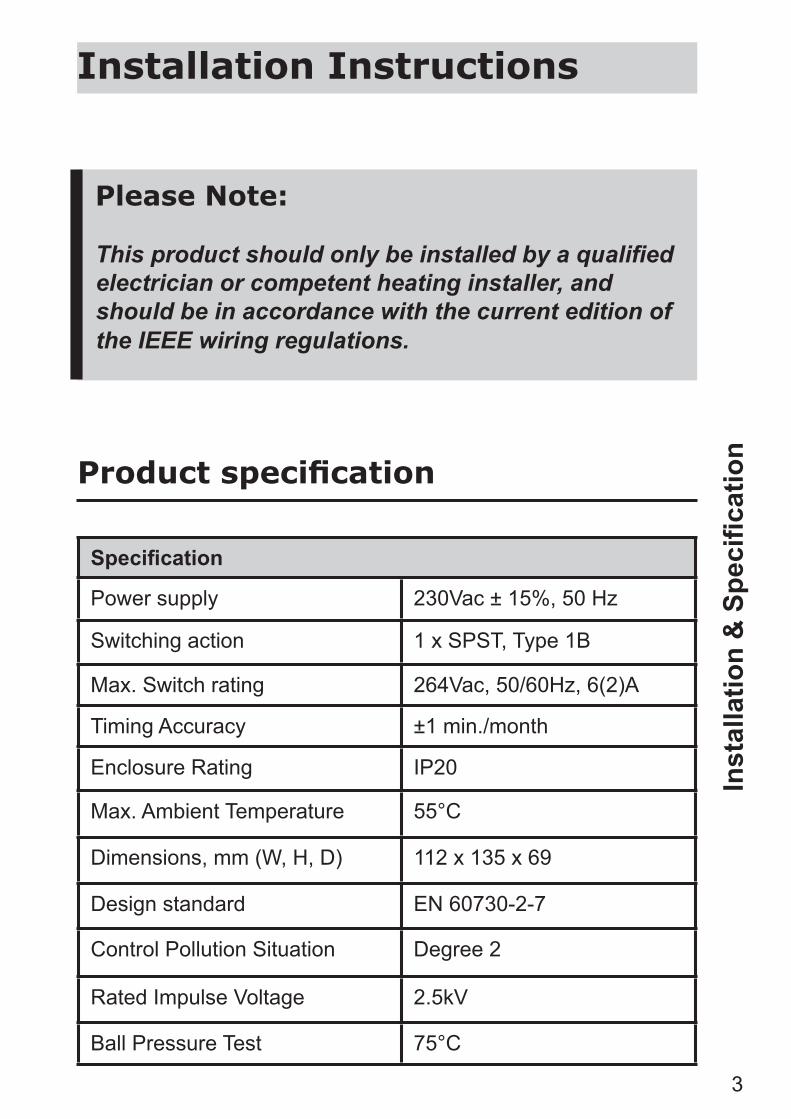
Please Note:
This product should only be installed by a qualifi ed electrician or competent heating installer, and should be in accordance with the current edition of the IEEE wiring regulations.
Specifi cation
Power supply 230Vac ± 15%, 50 Hz
Switching action 1 x SPST, Type 1B
Max. Switch rating 264Vac, 50/60Hz, 6(2)A
Timing Accuracy ±1 min./month
Enclosure Rating IP20
Max. Ambient Temperature 55°C
Dimensions, mm (W, H, D) 112 x 135 x 69
Design standard EN 60730-2-7
Control Pollution Situation Degree 2
Rated Impulse Voltage 2.5kV
Ball Pressure Test 75°C
Product specifi cation
Inst
alla
tion
& S
pecifi c
atio
n
Installation Instructions

4
Installation
1. Loosen the fi xing screw in the base of the unit to release the grey plastic Wiring Cover. Ensure the protective tape over the thumbwheel remains in place.
2. Holding the unit clockface downwards, press fi rmly in the centre of the wallplate and slide it from the module as shown.
Inst
alla
tion
Pre-Selector wheel
Selector switch
Plug-in replacement module
Wallplate/Terminal block (not with FRU units)
wallplate/terminal
block
plug-in module
NB. For FRU units - go straight to to point 4 on page 5

5
3. Fix the Wallplate/Terminal Block to the wall with countersunk No.8 woodscrews or to a steel box to BS 4662. 1970 or a surface mounting steel or moulded box having centres of 23/8” (60.3mm).
4. Referring to the Wiring Diagrams on page 6, connect the unit as shown. Ensure that terminals 3 and 6 are linked where required (Mains Voltage applications) with insulated cable capable of carrying full load current.
5. Ensure all dust and debris has been cleared away from the area, then plug the module fi rmly into the wallplate ensuring that the hook at the top of the wallplate engages with the slot at the back of the body. Press the module down until it locates solidly.
6. Cut a cable aperture in the Wiring Cover if necessary; replace the Wiring Cover, and tighten the fi xing screw.
7. Switch on Mains & test for correct operation as follows:
i) Remove protective tape from pre-selector wheel. ii) Remove dial cover & rotate the clock dial two
complete revolutions to clear the mechanism. ii) Check that all positions of the Selector Switch
and Tappets operate correctly. (See instructions in User Booklet.)
8. Replace the dial cover. Finally leave this booklet, containing the USER instructions with the Householder.
9. If the unit is to be left turned off and is in a dusty atmosphere, protect the pre-selector wheel by re-affi xing the protective tape.
IMPORTANT: Remove tape prior to putting unit into service.
Inst
alla
tion

6
Wiri
ng
102,
102
E5, 1
02E7
Wiring
L N
L N L N
L N
Motor
Brown
Call
Grey
Blue
HP2 spring return zone valve
Cylinder StatL641AOrange
To Boiler & Pump
Room StatCom
N
Room StatCom
Call
Boiler
Pump
Mains Supply
Mains Supply
Link Link LLNN
1 2 3 5 6 1 2 3 5 6
N
1 2
102 Terminals102 Terminals
C
1) Typical domestic gas or oil fired system with gravity hot water and pumped heating (if a room stat is not required, wire pump L
directly to terminal 2 on the 102).
2) Fully pumped system with cylinder stat in HW circiut and room stat and 2 port spring
return zone valve in heating circuit.

7
User Instructions
Your programmer
Your 102 mini-programmer allows you to switch your heating and hot water on and off at times that suit you.
Normally the 102 provides 2 ON periods and 2 OFF periods each day. However 1 ON and 1 OFF period can be obtained by using the Pre-Selector Wheel (see page 11).
You can choose whether the 102 controls your hot water & heating together, just the hot water or neither system (OFF) using the manual rocker switch.
Ove
rvie
w
Preselector wheel
Dial cover
Wiring cover
Rocker switch to manually select programme operation
8
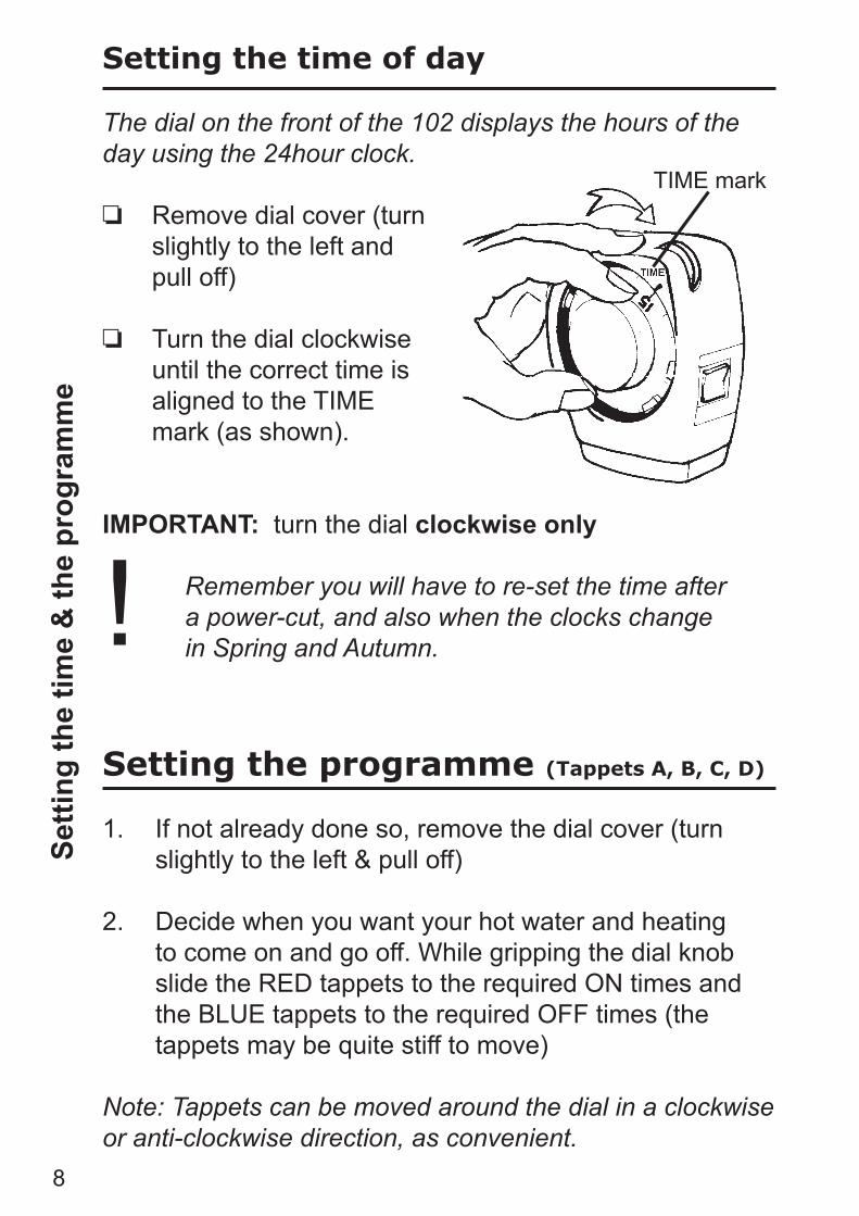
Setting the time of day
The dial on the front of the 102 displays the hours of the day using the 24hour clock.
Remove dial cover (turn slightly to the left and pull off)
Turn the dial clockwise until the correct time is aligned to the TIME mark (as shown).
IMPORTANT: turn the dial clockwise only
Remember you will have to re-set the time after a power-cut, and also when the clocks change in Spring and Autumn.
Setting the programme (Tappets A, B, C, D)
1. If not already done so, remove the dial cover (turn slightly to the left & pull off)
2. Decide when you want your hot water and heating to come on and go off. While gripping the dial knob slide the RED tappets to the required ON times and the BLUE tappets to the required OFF times (the tappets may be quite stiff to move)
Note: Tappets can be moved around the dial in a clockwise or anti-clockwise direction, as convenient.
TIME mark
Setti
ng th
e tim
e &
the
prog
ram
me
!

9
Example:
If you want your system ON between 8am and 10am and again between 4pm and 11pm, set the tappets as shown. (A to 8, B to 10, C to 16, D to 23).
Remember: Red tappets (A and C) switch ON Blue tappets (B and D) switch OFF
3. Ensure that the installer has removed the protective tape covering the pre-selector wheel.
4. Using the dial knob, rotate the dial completely at least twice, clockwise only, to clear the mechanism.
Setti
ng th
e pr
ogra
mm
e
A = 1st ONB = 1st OFFC = 2nd OND = 2nd OFF
10
Sele
ctin
g op
erat
ing
mod
e Selecting operating mode
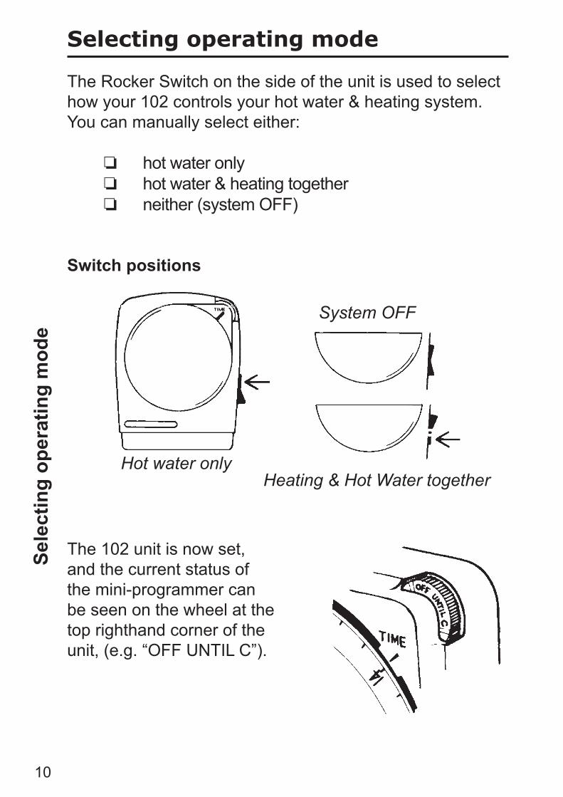
The Rocker Switch on the side of the unit is used to select how your 102 controls your hot water & heating system. You can manually select either:
hot water only hot water & heating together neither (system OFF)
Switch positions
The 102 unit is now set, and the current status of the mini-programmer can be seen on the wheel at the top righthand corner of the unit, (e.g. “OFF UNTIL C”).
Hot water only
System OFF
Heating & Hot Water together

11
Overriding the programe using the Pre-Selector wheel
The pre-selector wheel can be used to override the set programme on occasions when you need to change from your normal heating routine.
By turning the wheel anti-clockwise you can turn the unit ON when it is OFF and vice versa.
Example: Your programme is set so that your heating comes on
at 4pm but you arrive home earlier than usual, at 2pm and need the heating ON immediately.
Turn the wheel anti-clockwise until it displays ON UNTIL `D’ as shown.
Thus the system is turned ON manually at 2pm but will revert to the set programme at the next operation (i.e. OFF at 11pm)
Some other useful pre-selections are:
ALL DAY ON (1 ON/1 OFF) Turn the Wheel to display “ON UNTIL D”.
ALL DAY OFF Turn the Wheel to display “OFF UNTIL A”.
Note: Do not operate the pre-selector whilst a tappet is close to the TIME mark. This may cause the time of day setting of the clock to be altered, and the time would then need to be reset as shown on page 8.!
Tem
pora
ry o
verr
ides
Danfoss Randall LtdAmpthill RoadBedfordMK42 9ERTel: 01234 364621Fax: 01234 219705
Still having problems?
Call your local heating engineer:
Name:
Tel:
Visit our website:
www.danfoss-randall.co.uk
Email our technical department:
Call our technical department
0845 121 7505(8.45-5.15 Mon-Thurs, 8.45-4.45 Fri)
For a large print version of these instructions please contact the Marketing Services Department on 0845 121 7400.
Part No 7478v03 06/08