INSTALLATION USE AND - Jens-S · installation use and maintenance manual serie mv/v ... 1.1.1...
35
Transcript of INSTALLATION USE AND - Jens-S · installation use and maintenance manual serie mv/v ... 1.1.1...


INSTALLATION USE AND MAINTENANCE MANUALSerie MV/V – MRV/RV
INDEX
1.0 GENERAL INFORMATION …………………………………………………..…..….. Pag.3 1.1.1 EQUIPMENT IDENTIFICATION 1.1.2 MANUFACTURER’S LIABILITY 1.1.3 OPERATING LIMITS AND CONDITIONS
2.0 GEARBOXES’ATEX INFORMATION ……………………….……………..…..….. Pag.52.1 EQUIPMENT IDENTIFICATION 2.2 CONFORMITY TO ATEX STANDARDS2.3 BUILDING CHARACTERISTIC ATEX GEARBOXES 2.4 ATEX CERTIFICATE
3.0 STORAGE AND INSTALLATION ………………………………………………….... Pag.83.1 STORAGE AND WAREHOUSE 3.2 INSTALLATION3.3 STARTING
4.0 MAINTENANCE …………………………………………………..…………………….….. Pag.11 4.1.1 ROUTINE MAINTENANCE 4.1.2 LUBRICANTS4.1.3 CHECKING EFFICIENCY
5.0 PROBLEM DURING OPERATION ………………………………………………….. Pag.145.1 CAUSE AND REMEDY
6.0 MOUNTING POSITION ………………………………………………………..…..….. Pag.15
7.0 SPARES TABLES …………………………………………………..…………………..….. Pag.25
8.0 SPARES TABLES …………………………………………………..…………………..….. Pag.25
9.0 SPARES TABLES …………………………………………………..…………………..….. Pag.25
2

1.0 GENERAL INFORMATION
1.1 EQUIPMENT IDENTIFICATION
A
BC
D
E F
a) Gearbox’s descriptionb) Ratioc) Product identificationd) Gearbox coded) Datee) Operator code
1.2 NOTE AND MANUFACTURER’S LIABILITY
The manufacturer declines all liability for cases of: - use of the gearbox in violation of local laws on safety and accident prevention at
work- use as overgear - modifications and/or tampering- incorrect installations - non-observance of instruction given in this manual - incorrect power supply - work done by unqualified or unsuitable person - immersion in water or other liquids - use in environment with different pressure than the atmospheric one - use in aggressive or brackish environment
The safety also depends on the following elements: - use of gearbox within its operatine limits
- diligently observance of the routine maintenance schedule - exclusive use of original spare parts.
N.B. :The instructions given in this manual do not substitute, but summarisethe provisions of applicable safety legislation.
3

1.3 OPERATING LIMITS AND CONDITIONS
- the gearbox must be installed as specified in the order and as given on the serial plate
- the permissible ambient temperature is: -20° < ta < +40° C - the instructions given in the Use and Maintenance Manual, must be followed- the use in a poorly lit area must provide for the use of additional lamps with
applicable safety legislation - the catalogue data refers to standard installation conditions: smaller spaces could
cause anincrease of temperature; in this case ask the manufacturer
For gearboxes ATEX it is also valid:
- The input speed must not exceed 1500 rpm - Do not use the gearbox, if not authorized ATEX, in a potentially esplosive
atmosphere
Failure to obtain said conditions voids the warranty of the manufacturer and incase of ATEX gearboxes, the certification too.
4
2.0 GEARBOXES’ ATEX INFORMATIONS
2.1 EQUIPMENT IDENTIFICATION
BC
DE
FGN° certificate
ATEXH I
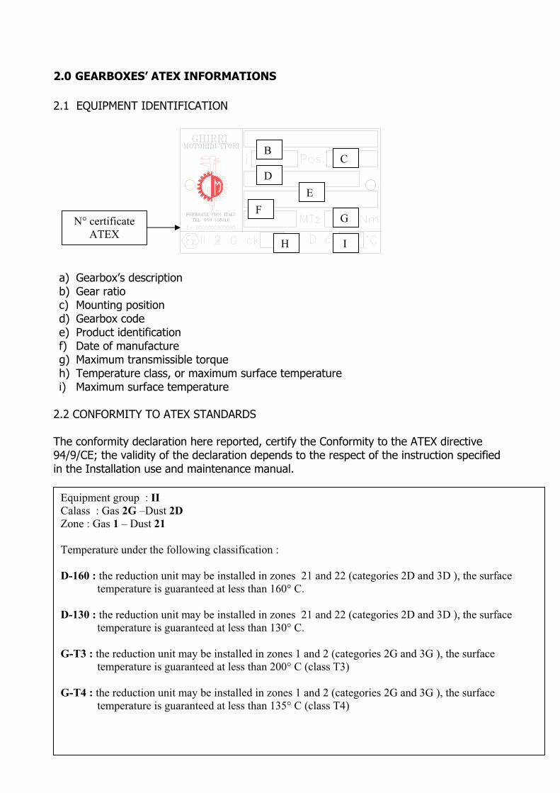
a) Gearbox’s descriptionb) Gear ratio c) Mounting positiond) Gearbox codee) Product identificationf) Date of manufactureg) Maximum transmissible torque h) Temperature class, or maximum surface temperature i) Maximum surface temperature
2.2 CONFORMITY TO ATEX STANDARDS
The conformity declaration here reported, certify the Conformity to the ATEX directive 94/9/CE; the validity of the declaration depends to the respect of the instruction specified in the Installation use and maintenance manual.
Equipment group : IICalass : Gas 2G –Dust 2DZone : Gas 1 – Dust 21
Temperature under the following classification :
D-160 : the reduction unit may be installed in zones 21 and 22 (categories 2D and 3D ), the surfacetemperature is guaranteed at less than 160° C.
D-130 : the reduction unit may be installed in zones 21 and 22 (categories 2D and 3D ), the surface temperature is guaranteed at less than 130° C.
G-T3 : the reduction unit may be installed in zones 1 and 2 (categories 2G and 3G ), the surface temperature is guaranteed at less than 200° C (class T3)
G-T4 : the reduction unit may be installed in zones 1 and 2 (categories 2G and 3G ), the surface temperature is guaranteed at less than 135° C (class T4)
The applicability of these options is subjet to the type of reduction unit in question and is given in the selection table.
2.3 BUILDING CHARACTERISTIC ATEX GEARBOXES
- Viton seal rings- Twin-lip seals on slow shaft - No plastic components - Marking on rating plate stating protection category and type - Presence of irreversible temperature-indicators at strategic points - Thread locker on all external bolts - Vent caps with anti-intrusion valve- Only uses synthetic lubricants (Polyglycol or Polyalkalene Glicol family)- Seal in zones with moving couplings and external threaded seats- Products and components suitable for use at temperatures above envisaged
operating temperatures - No sliding metal components outside the reduction unit
6

2.4 ATEX CERTIFICATE
7
3.0 STORAGE AND INSTALLATION
3.1 STORAGE AND WAREHOUSE
The reducers can be stored in an inoperative condition (normal industrial environment) without having to take any special precautions for a period of about 6 months; if theyremain inoperative for a longer period, the surface protective devices on the rotating partsshould be reset and the lubricant topped up completely.
At the end of the storage, before the reducer is put back into operation do the following: - The output shafts and external surfaces must be thoroughly cleaned of all rustproofing product or other impurities
- (n.b. : in case of ATEX gearbox, the previous disposition has to be done outside the explosion hazard area)
- the solvent must not touch the seal rings as this can damage them and render them ineffective.
- if the oil or protective material used during storage is not compatible with the oil used during the machine’s operation, the interior of the unit must be thoroughlycleaned before filling with the operating oil.
3.2 INSTALLATION
It’s very important that the following standards be met when installing the gear reducer and/or gearmotor:
- Make sure that the gear reducer is aligned with the motor and with the operating machine.
- Ensure that the reducer is secured firmly to avoid any vibration.
- The elements (cable or solid) must be mounted on the shafts in a workmanlike manner, without forcing, to ensure that the couplings are sound and thereby avoiding any damageto the bearings or other parts of the reducer. The elements in question must be machined to ISO H7 tolerance levels.
- If the reducer is painted, the rotating parts, control devices (oil indicator lamps) andparticularly the oil seals, should be protected to ensure that they are kept in good workingorder.
8
- Before putting the machine into operation, check that the position of the oil levelindicator and the drain plug are appropriate in relation to the position in which the reducerhas been mounted and that there is adequate oil to lubricate the internal working parts.
- If the machine is installed in the open air or in environments subjected to particularly harsh conditions, a rust-proofing paint should be used and water-repellent grease should be applied to the rotating parts.
- When the reducer is supplied without motor, check that the shaft and motor flange tolerances satisfy IEC Standards. Clean off any traces of dirt or paint from the shaft,centring pin and flange plate. Couple the elements without forcing them in any way.
In case of ATEX gearbox, must be add the following disposition:
Category 2D gear units must be installed in compliance with the provisions of standards EN 1127-1 EN 50281-2.All maintenance, assembly and disassembly work must be done outside the explosion hazard area by trained personnel.
Install guards to prevent the hazardous accumulation of dust and liquids on the seals.
Only install the gear unit in the motor execution and mounting position specified on the order.
Do not connect any object with electrical resistance greater than 109 ohm to the gear unit.
Check that all accessory components (cables, cable glands, etc. ) comply with ATEX directive.
3.3 STARTING
The gearbox has been tested by the manufacturer. Any way during the starting operation it is necessary to respect following instructions:
� The machine incorporating the gear unit must be comply with the provisions of theMachinery Directive 98/37/CE and any other applicable safety legislation.
� The gear unit’s mounting position in the installation must correspond to that prescribed and indicated on the nameplate.
9
� The motor power supply must correspond to that indicated on the motor within thetollerances indicated in the regulations in force
� The oil level must be as indicated in the catalogue and oil leaks should not be present
� The starting must be in a gradual way avoiding to put the nominal torqueimmediately on the gear unit
� The unit musn’t run noisily or with excessive vibration
� The environment temperature must be within the allowed range
In case of ATEX gearboxes it must be add following disposition:
� The machine incorporating the gearbox must comply with the provisions of the Directive 94/9/CE.
� Check that assembly is not carried out in a potentially explosive atmosphere.
� Check that there is no dust deposits thicker than 5 mm on the gearbox. Anyway thegearbox must be clean before starting.
� Check that during operation, the gearbox is sufficiently ventilated and that it is not subject to radiation from external heat sources.
� Check that the maximum operating temperature after 3 hours of starting at full load is not higher than the standard temperature class of the gearbox. In case stopthe gearbox at once and contact the G.M. technical service.
10

4.0 MAINTENANCE
4.1 ROUTINE MAINTENANCE
Generally the following rules should be followed: periodically check that the exterior of the assembly is clean, periodically check of eventual lubricant’s leaks, periodic replacement of lubricant if gearbox is not lubricated for life.
Periodic check provides too:
- check the breather hole in the plug is clean(when present) - check through the level plugs the correct quantity of lubricant, if it is necessary, procedewith refilling of lubricant of the same brand or anyway compatible with that of the gearbox.
In case of ATEX gearbox is indicated the following frequency :
Frequency Component Type of work Operation
5000 hours Seals and gaskets gearbox
Check wear or ageing If it is necessary replacing of the oil seals ring
1000 hours Lubricant Check oil level and checkfor leaks
Maintenance or refilling
1000 hours Hole plug Check hole’s cleaning Maintenance1000 hoursof operationor every 3months
Surface Check that there is no dustdeposits thicker than 5mm
Periodic cleaning
1000 hoursof operationor every 3months
Surface Check the surfacetemperature
Check of the temperature indicator
Every 5000 hours ofoperation
Gearbox General repair of the gearbox (if it is notnecessary in advance because of anomalies)
Replacing of bearingsand mechanical components which are weared
11

4.2 LUBRICANT
Synthetic Oli Mineral Oil
AGIP TELIUM OIL VSF 320 (*) BLASIA 220SHELL Tivela OIL SC 320 OMALA 220 KLUBER Syntheso D 220 EP Lamora 220FINA Giran S 320 Giran 220ESSO Glycolube Range 220 Spartan EP 220
In case of ATEX gearbox, greases and oils compatibles are:
Greases
For greased gear trainsShell TVX Compound BShell Tivela GL 00
To facilitate coupling of cylindrical parts Kluberpaste 46 MR 401
For greasing contact seals ITP Fluorocarbon gel 880
Oils(as alternatives to ENI Telium oil VSF 320)
� Shell : Tivela Oil SC320 � Aral : Degol GS 320� Kluber : Klubersynth GH 6 320� Total : Carter SY 320� Mobil : Glygoyle HE 320
12
4.2 4.3 CHECKING EFFICIENCY
Remove dust deposits from the gear unit.Check the noise and the presence of eventual vibration. Check the power absorption of voltage is within limit indicated in the name plate.Check for lubricant leaks.
In case of ATEX gearboxes :
The following activities should be integrated in the internal procedure.
13

5.0 PROBLEM DURING OPERATION
The following table shows a series of problems with a description of possible remedies.
However the information given is for reference only, as all the drives manufacturer by G.M. are thoroughly tested and checked before shipment.
Tampering with the assembly without prior authorization from G.M. immediately invalidates the warrenty and makes it impossible to ascertain the causes of a defect or malfunction.
problem cause actionThe motor does not start. Problems with power supply.
Defective motor.Wrong size of motor.
Replace electric motor and/or check power supply.
Current absorbed by the motor is greater than shown on the data plate.
Wrong size of motor. Check the application.
Temperature of the motor housing is very high.
Wrong size of motor/defective motor.
Check the application.
Temperature of the motor housing is very high.
Wrong size of reduction unit.Mounting position does notcomply with the order.
Check the application and/or mounting position complieswith the order.
Oil leak from oil seal. Detective oil seal.Oil sealdamaged during shipment. Defective motor shaft.
Replace the oil seal, return the assembly to G.M. if motor shaft is damaged.
Oil leak from joint. Flat gasket or O-ring damaged.
Return the assembly to G.M.
Intermittent noise from the gears.
Dents in the gear wheels. Return the assembly toG.M.(if the noise has effect on the application).
Noise(whine)from the drive assembly.
Bearings incorrectly adjusted. Gears with mesh errors. Insufficient lubricant.
Check of lubricant and/or return the assembly to G.M.
Electric motor vibrates. Measurement of the assembly coupling.
Replace electric motor and/or check geometric tolerance of flange onelectric motor.
The main shaft rotates the wrong way.
Incorrect connection of the electric motor.
Swap phases.
14

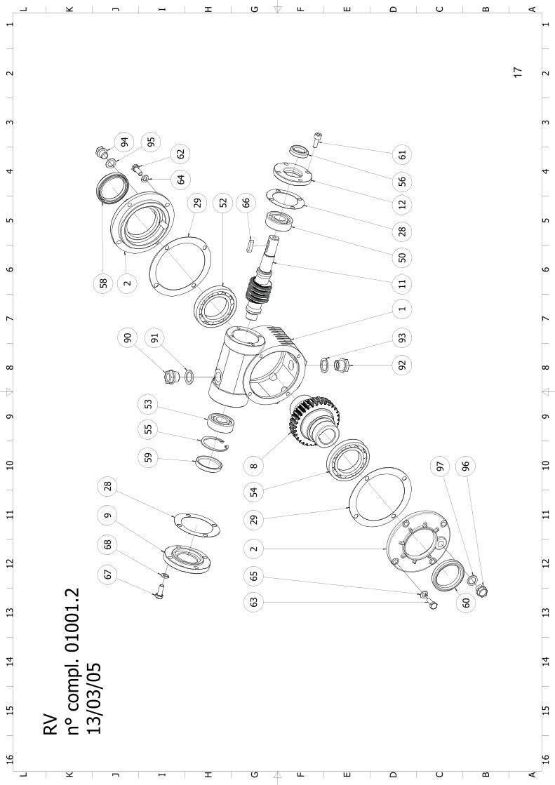
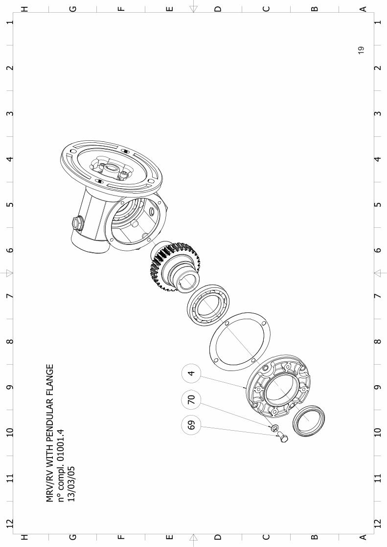
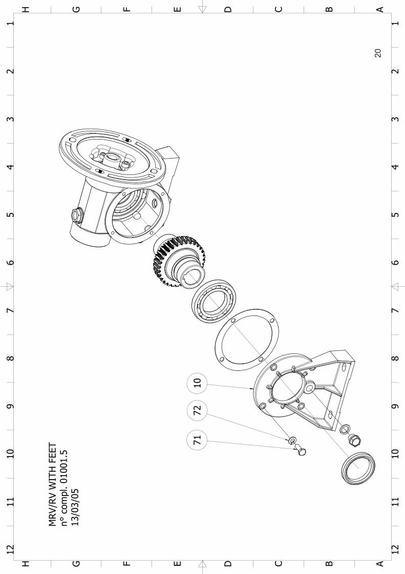
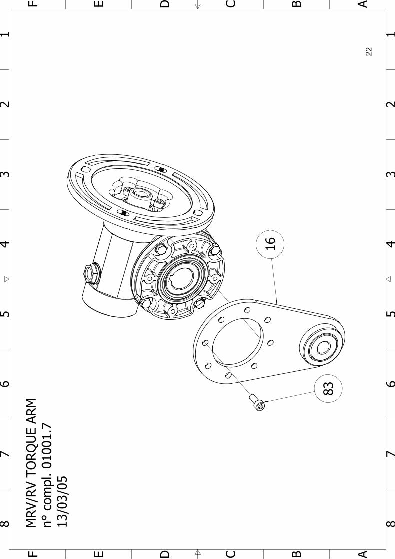
6.0 SPARES TABLE
GEARED MOTOR REDUCERS MRV/RV
15

1 1
2 2
3 3
4 4
5 5
6 6
7 7
8 8
9 9
10 10
11 11
12 12
13 13
14 14
15 15
16 16A
A
BB
CC
DD
EE
FF
GG
HH
II
JJ
KK
LL
MRV
PAM
n° c
ompl
. 010
01.1
13/0
3/05
6157
628
517
192
93
9697
6365
60
229
548
5355
5990 91
94 95 58 62 64 2
29 52
289
6867
16
1 1
2 2
3 3
4 4
5 5
6 6
7 7
8 8
9 9
10 10
11 11
12 12
13 13
14 14
15 15
16 16A
A
BB
CC
DD
EE
FF
GG
HH
II
JJ
KK
LL
RV n° c
ompl
. 010
01.2
13/0
3/05
6156
1228
5011
193
92
97 966063
652
2954
8
5955
53
90 91
29 52 66
6462
9594258
289
6867
17

1 1
2 2
3 3
4 4
5 5
6 6
7 7
8 8
9 9
10 10
11 11
12 12
AA
BB
CC
DD
EE
FF
GG
HH
MRV
/RV
WIT
HO
UTP
UT
FLAN
GE
n° c
ompl
. 010
01.3
13/0
3/05
74 73
3
18
1 1
2 2
3 3
4 4
5 5
6 6
7 7
8 8
9 9
10 10
11 11
12 12
AA
BB
CC
DD
EE
FF
GG
HH
MRV/
RV
WIT
H P
END
ULA
R F
LAN
GE
n° c
ompl
. 010
01.4
13/0
3/05
6970
4
19
1 1
2 2
3 3
4 4
5 5
6 6
7 7
8 8
9 9
10 10
11 11
12 12
AA
BB
CC
DD
EE
FF
GG
HH
MRV
/RV
WIT
HFE
ETn°
com
pl. 0
1001
.513
/03/
05
7172
10
20

1 1
2 2
3 3
4 4
5 5
6 6
7 7
8 8
AA
BB
CC
DD
EE
FF
MRV
/RV
OU
TPU
T SH
AFTS
n° c
ompl
. 010
01.6
13/0
3/05
1575
76
8281
80
15.1
0
77
7879
21
1 1
2 2
3 3
4 4
5 5
6 6
7 7
8 8
AA
BB
CC
DD
EE
FF
MRV
/RV
TORQ
UE
ARM
n° c
ompl
. 010
01.7
13/0
3/05
83
16
22

MR
V/R
VTA
BLE
1U
pdat
e 11
/03/
2005
05Q
10Q
20Q
30Q
40Q
50Q
60Q
70Q
Pro
g.P
os.
Den
omin
atio
nP
/C
011
Cas
ing
P01
0050
11
0101
001
101
0200
11
0103
001
101
0400
11
0105
001
101
0600
11
0107
001
101
2La
tera
l cov
erP
0100
502
101
0100
21
0102
002
101
0300
21
0104
002
101
0500
21
0106
002
101
0700
21
013
Out
put f
lang
eP
0100
503
101
0100
31
0102
003
101
0300
31
0104
003
101
0500
31
0106
003
101
0700
31
014
Pen
dula
r fla
nge
P01
0050
41
0101
004
101
0200
41
0103
004
101
0400
41
0105
004
101
0600
41
0107
004
101
6M
otor
flan
geP
0100
506
101
0100
61
0102
006
101
0300
61
0104
006
101
0500
61
0106
006
101
0700
61
017
Wor
m s
haft
PA
MP
0100
507
101
0100
71
0102
007
101
0300
71
0104
007
101
0500
71
0106
007
101
0700
71
018
Wor
m w
heel
P01
0050
81
0101
008
101
0200
81
0103
008
101
0400
81
0105
008
101
0600
81
0107
008
101
9C
lose
d co
ver
P-
--
--
--
-01
0400
91
0105
009
101
0600
91
0107
009
101
10Fe
etP
0100
510
101
0101
01
0102
010
101
0301
01
0104
010
101
0501
01
0106
010
101
0701
01
0111
Wor
m s
haft
RV
P01
0051
11
0101
011
101
0201
11
0103
011
101
0401
11
0105
011
101
0601
11
0107
011
101
12C
over
P01
0051
21
0101
012
101
0201
21
0103
012
101
0401
21
0105
012
101
0601
21
0107
012
101
15O
utpu
t sha
ftP
0100
515
101
0101
51
0102
015
101
0301
51
0104
015
101
0501
51
0106
015
101
0701
51
0115
.10
Dou
ble
outp
ut s
haft
P01
0051
5.10
101
0101
5.10
101
0201
5.10
101
0301
5.10
101
0401
5.10
101
0501
5.10
101
0601
5.10
101
0701
5.10
101
16To
rque
arm
P01
0051
61
0101
016
101
0201
61
0103
016
101
0401
61
0105
016
101
0601
61
0106
016
101
28G
aske
tP
0100
528
101
0102
81
0102
028
101
0302
81
0104
028
101
0502
81
0106
028
101
0702
81
0129
Gas
ket
P01
0052
92
0101
029
201
0202
92
0103
029
201
0402
92
0105
029
201
0602
92
0107
029
2-
50B
earin
g 1
on w
orm
sha
ftC
6202
162
031
3020
41
3020
51
3020
31
3020
71
3030
71
3021
11
-51
Bea
ring
1 on
wor
m s
haft
C51
104
151
105
151
106
151
107
132
007
132
009
132
010
132
013
1-
52B
earin
g 2
on w
orm
sha
ftC
1600
61
1600
81
1600
91
1600
91
6010
160
111
6213
160
181
-53
Bea
ring
1 on
wor
m w
heel
C
6202
162
031
3020
41
3020
51
3020
61
3020
71
3030
71
3021
11
-54
Bea
ring
2 on
wor
m w
heel
C16
006
116
008
116
009
116
009
160
101
6011
162
131
6018
1-
55S
eege
r UN
I 743
7C
I 35
1I 4
01
I 47
1I 5
21
--
--
--
--
-56
Oil
seal
ring
DIN
376
0C
15x3
0x7
117
x28x
71
20x3
0x8
125
x35x
81
30x4
5x8
135
x47x
81
35x4
7x8
155
x70x
81
-57
Oil
seal
ring
DIN
376
0C
20x3
0x8
125
x35x
81
30x4
0x8
135
x45x
81
35x4
7x8
145
x60x
81
50x6
5x8
165
x90x
101
-58
Oil
seal
ring
DIN
376
0C
30x4
5x8
140
x52x
81
45x6
0x8
145
x65x
101
50x7
0x10
155
x70x
81
65x9
0x10
190
x120
x12
1-
59C
over
RC
AC
35x7
140
x71
47x7
152
x71
--
--
--
--
-60
Oil
seal
ring
DIN
376
0C
30x4
5x8
140
x52x
81
45x6
0x8
145
x65x
101
50x7
0x10
155
x70x
81
65x9
0x10
190
x120
x12
1-
61S
crew
DIN
EN
240
14C
M5x
204
M6x
224
M6x
224
M8x
254
M8x
254
M8x
254
M8x
254
M8x
306
-62
Scr
ew D
IN E
N 2
4014
CM
5x16
4M
6x18
4M
6x18
8M
6x18
8M
6x20
8M
8x22
8M
8x25
8M
10x3
08
-63
Scr
ew D
IN E
N 2
4014
CM
5x16
4M
6x18
4M
6x18
8M
6x18
8M
6x20
8M
8x22
8M
8x25
8M
10x3
08
-64
Was
her D
IN 1
28C
Dn
54
Dn
64
Dn
68
Dn
68
Dn
68
Dn
88
Dn
88
Dn
108
-65
Was
her D
IN 1
28C
Dn
54
Dn
64
Dn
68
Dn
68
Dn
68
Dn
88
Dn
88
Dn
108
-66
Key
DIN
688
5C
5x5x
201
5x5x
201
6x6x
251
6x6x
301
8x7x
351
8x7x
451
10x8
x60
110
x8x6
01
-67
Scr
ew D
IN E
N 2
4014
C-
--
--
--
-M
8x22
4M
8x22
4M
8x25
4M
8x30
6-
68W
ashe
r DIN
128
C-
--
--
--
-D
n 8
4D
n 8
4D
n 8
4D
n 8
6-
69S
crew
DIN
EN
240
14C
M5x
164
M6x
184
M6x
188
M6x
188
M6x
208
M8x
228
M8x
258
M10
x30
8
Siz
e (c
ompo
nent
for g
ear s
ize)
23
-70
Was
her D
IN 1
28C
Dn
54
Dn
64
Dn
68
Dn
68
Dn
68
Dn
88
Dn
88
Dn
108
-71
Scr
ew D
IN E
N 2
4014
CM
5x16
4M
6x18
4M
6x18
8M
6x18
8M
6x20
8M
8x22
8M
8x25
8M
10x3
08
-72
Was
her D
IN 1
28C
Dn
54
Dn
64
Dn
68
Dn
68
Dn
68
Dn
88
Dn
88
Dn
108
-73
Scr
ew D
IN E
N 2
4014
CM
5x16
4M
6x18
4M
6x18
8M
6x18
8M
6x20
8M
8x22
8M
8x25
8M
10x3
08
-74
Was
her D
IN 1
28C
Dn
54
Dn
64
Dn
68
Dn
68
Dn
68
Dn
88
Dn
88
Dn
108
-75
Key
DIN
688
5C
6x6x
301
6x6x
301
8x7x
401
8x7x
451
10x8
x50
110
x8x5
01
12x8
x60
116
x10x
901
-76
Key
DIN
688
5C
6x6x
501
6x6x
601
8x7x
801
8x7x
801
10x8
x90
110
x8x9
01
12x8
x100
116
x10x
120
1-
77K
ey D
IN 6
885
C6x
6x30
16x
6x30
18x
7x40
18x
7x45
110
x8x5
01
10x8
x50
112
x8x6
01
16x1
0x90
1-
78K
ey D
IN 6
885
C6x
6x50
16x
6x60
18x
7x80
18x
7x80
110
x8x9
01
10x8
x90
112
x8x1
001
16x1
0x12
01
-79
Key
DIN
688
5C
6x6x
301
6x6x
301
8x7x
401
8x7x
451
10x8
x50
110
x8x5
01
12x8
x60
116
x10x
901
-80
Scr
ew D
IN E
N 2
4014
CM
6x18
1M
6x18
1M
8x20
1M
8x20
1M
10x2
51
M10
x25
1M
10x3
01
M12
x45
1-
81W
ashe
r DIN
128
CD
n 6
1D
n 6
1D
n 8
1D
n 8
1D
n 10
1D
n 10
1D
n 10
1D
n 12
1-
82W
ashe
r C
6,2x
28x4
16,
2x28
x41
8,2x
28x4
18,
2x40
x41
10,5
x56x
61
10,5
x56x
61
10,5
x56x
61
12,5
x70x
61
-83
Scr
ew D
IN E
N IS
O 4
762
CM
6x14
1M
6x14
1M
8x20
1M
8x18
1M
10x2
21
M12
x20
1M
12x1
81
M14
x22
1-
90Fi
lling
plu
gC
3/8"
Gas
13/
8" G
as1
3/8"
Gas
13/
8" G
as1
3/8"
Gas
13/
8" G
as1
3/8"
Gas
13/
8" G
as1
-91
Gas
ket
C3/
8" G
as1
3/8"
Gas
13/
8" G
as1
3/8"
Gas
13/
8" G
as1
3/8"
Gas
13/
8" G
as1
3/8"
Gas
1-
92Fi
lling
plu
gC
--
--
3/8"
Gas
13/
8" G
as1
3/8"
Gas
13/
8" G
as1
3/8"
Gas
13/
8" G
as1
-93
Gas
ket
C-
--
-3/
8" G
as1
3/8"
Gas
13/
8" G
as1
3/8"
Gas
13/
8" G
as1
3/8"
Gas
1-
94Fi
lling
plu
gC
--
--
3/8"
Gas
13/
8" G
as1
3/8"
Gas
13/
8" G
as1
3/8"
Gas
13/
8" G
as1
-95
Gas
ket
C-
--
-3/
8" G
as1
3/8"
Gas
13/
8" G
as1
3/8"
Gas
13/
8" G
as1
3/8"
Gas
1-
96Fi
lling
plu
gC
--
--
3/8"
Gas
13/
8" G
as1
3/8"
Gas
13/
8" G
as1
3/8"
Gas
13/
8" G
as1
-97
Gas
ket
C-
--
-3/
8" G
as1
3/8"
Gas
13/
8" G
as1
3/8"
Gas
13/
8" G
as1
3/8"
Gas
1
05Q
10Q
20Q
30Q
40Q
50Q
60Q
70Q
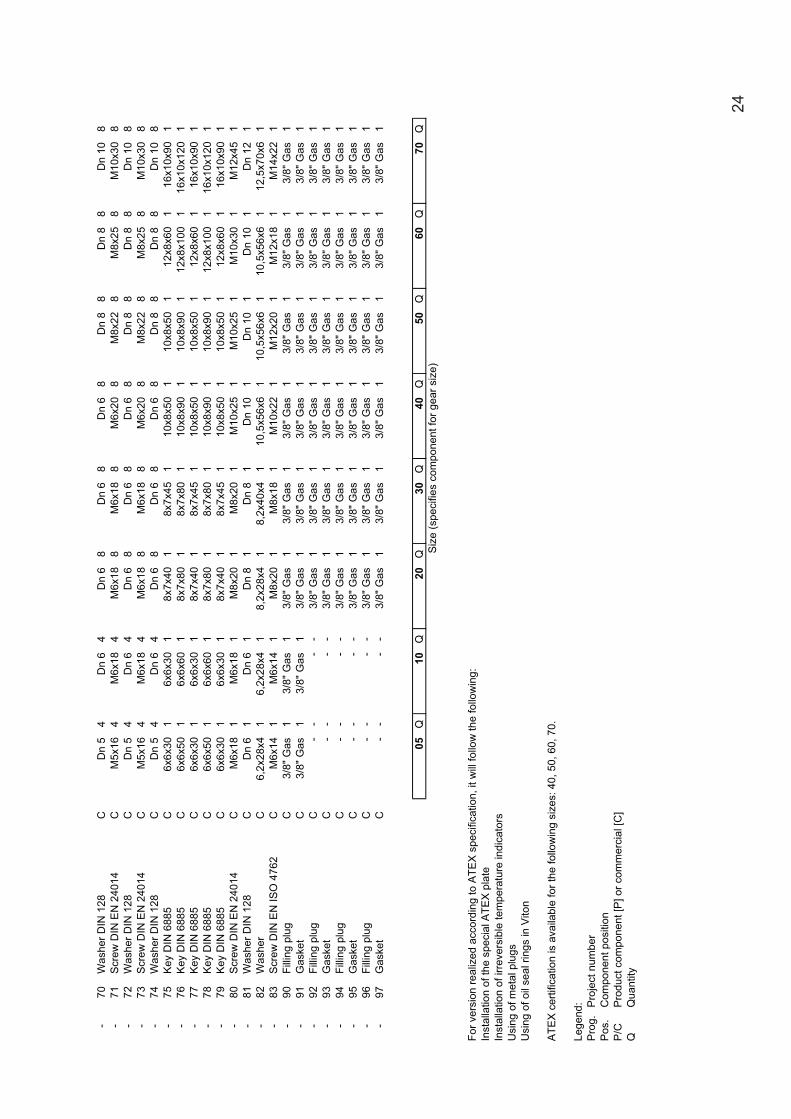
For v
ersi
on re
aliz
ed a
ccor
ding
to A
TEX
spe
cific
atio
n, it
will
follo
w th
e fo
llow
ing:
Inst
alla
tion
of th
e sp
ecia
l ATE
X p
late
Inst
alla
tion
of ir
reve
rsib
le te
mpe
ratu
re in
dica
tors
Usi
ng o
f met
al p
lugs
Usi
ng o
f oil
seal
ring
s in
Vito
n
ATE
X c
ertif
icat
ion
is a
vaila
ble
for t
he fo
llow
ing
size
s: 4
0, 5
0, 6
0, 7
0.
Lege
nd:
Pro
g.P
roje
ct n
umbe
r P
os.
Com
pone
nt p
ositi
on
P/C
Pro
duct
com
pone
nt [P
] or c
omm
erci
al [C
]Q
Qua
ntity
Siz
e (s
peci
fies
com
pone
nt fo
r gea
r siz
e)
24

B 3
B 6
B 7
B 8
V 5
V 6
7.0
MRV
/RV
MO
UN
TIN
G P
OSI
TIO
NS
n° c
ompl
. 010
01.8
13/0
3/05
25

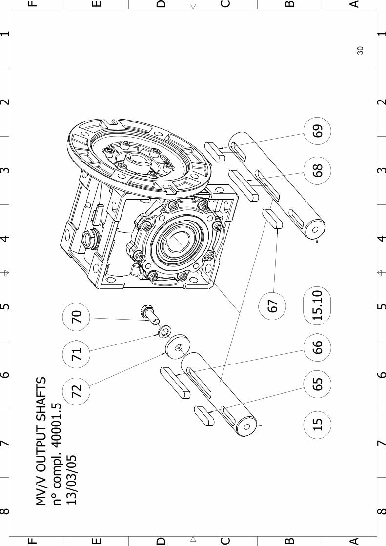
8.0 SPARES TABLE
GEARED MOTOR REDUCERS MV/V
26

1 1
2 2
3 3
4 4
5 5
6 6
7 7
8 8
9 9
10 10
11 11
12 12
13 13
14 14
15 15
16 16A
A
BB
CC
DD
EE
FF
GG
HH
II
JJ
KK
LL
MV
PAM
n° c
ompl
. 400
01.1
13/0
3/05
6062
804
548
53
5956
1752
58
17
5155
576
61
93
92
9594
9190
27

1 1
2 2
3 3
4 4
5 5
6 6
7 7
8 8
9 9
10 10
11 11
12 12
13 13
14 14
15 15
16 16A
A
BB
CC
DD
EE
FF
GG
HH
II
JJ
KK
LL
V n° c
ompl
. 400
01.2
13/0
3/05
6062
804
548
53
5217
5659
58
111
5155
57
63
92
93
90 91
9594
28

1 1
2 2
3 3
4 4
5 5
6 6
7 7
8 8
AA
BB
CC
DD
EE
FF
MV/
VW
ITH
OU
TPU
T FL
ANG
En°
com
pl. 4
0001
.313
/03/
05
64
3
29
1 1
2 2
3 3
4 4
5 5
6 6
7 7
8 8
AA
BB
CC
DD
EE
FF
MV/
VO
UTP
UT
SHAF
TSn°
com
pl. 4
0001
.513
/03/
0570
7172
1565
6615
.10
67
6869
30

1 1
2 2
3 3
4 4
5 5
6 6
7 7
8 8
AA
BB
CC
DD
EE
FF
MV/
VTO
RQU
E AR
Mn°
com
pl. 4
0001
.413
/03/
05
73
16
31
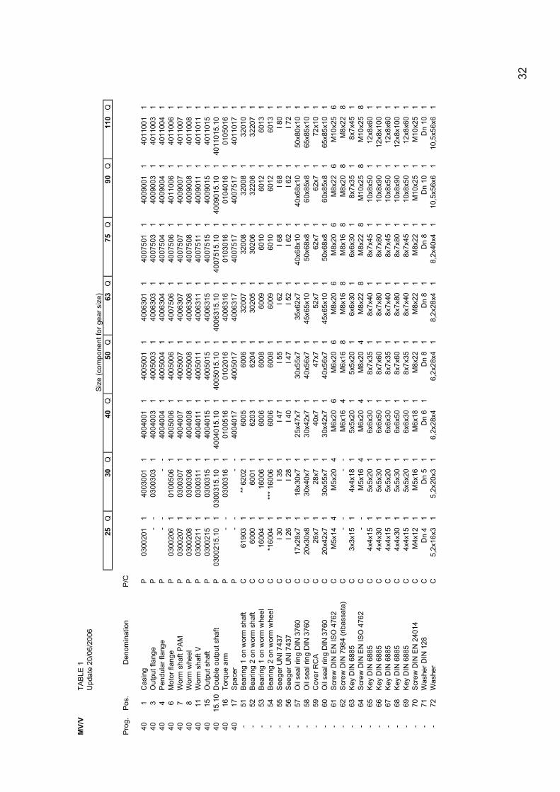
MV/
VTA
BLE
1U
pdat
e 20
/06/
2006
25Q
30Q
40Q
50Q
63Q
75Q
90Q
110
Q
Pro
g.P
os.
Den
omin
atio
nP
/C
401
Cas
ing
P03
0020
11
4003
001
140
0400
11
4005
001
140
0630
11
4007
501
140
0900
11
4011
001
140
3O
utpu
t fla
nge
P-
-03
0030
31
4004
003
140
0500
31
4006
303
140
0750
31
4009
003
140
1100
31
404
Pen
dula
r fla
nge
P-
--
-40
0400
41
4005
004
140
0630
41
4007
504
140
0900
41
4011
004
140
6M
otor
flan
geP
0300
206
101
0050
61
4005
006
140
0500
61
4007
506
140
0750
61
4011
006
140
1100
61
407
Wor
m s
haft
PA
MP
0300
207
103
0030
71
4004
007
140
0500
71
4006
307
140
0750
71
4009
007
140
1100
71
408
Wor
m w
heel
P03
0020
81
0300
308
140
0400
81
4005
008
140
0630
81
4007
508
140
0900
81
4011
008
140
11W
orm
sha
ft V
P03
0021
11
0300
311
140
0401
11
4005
011
140
0631
11
4007
511
140
0901
11
4011
011
140
15O
utpu
t sha
ft P
0300
215
103
0031
51
4004
015
140
0501
51
4006
315
140
0751
51
4009
015
140
1101
51
4015
.10
Dou
ble
outp
ut s
haft
P03
0021
5.10
103
0031
5.10
140
0401
5.10
140
0501
5.10
140
0631
5.10
140
0751
5.10
140
0901
5.10
140
1101
5.10
140
16To
rque
arm
P-
-03
0031
61
0100
516
101
0201
61
4006
316
101
0301
61
0104
016
101
0501
61
4017
Spa
cer
P-
--
-40
0401
71
4005
017
140
0631
71
4007
517
140
0751
71
4011
017
1-
51B
earin
g 1
on w
orm
sha
ftC
6190
31
** 6
202
160
051
6006
132
007
132
008
132
008
132
010
1-
52B
earin
g 2
on w
orm
sha
ftC
6000
160
011
6203
162
041
3020
51
3020
61
3220
61
3220
71
-53
Bea
ring
1 on
wor
m w
heel
C16
004
116
006
160
061
6008
160
091
6010
160
121
6013
1-
54B
earin
g 2
on w
orm
whe
elC
*160
041
***
1600
61
6006
160
081
6009
160
101
6012
160
131
-55
See
ger U
NI 7
437
CI 3
01
I 35
1I 4
71
I 55
1I 6
21
I 68
1I 6
81
I 80
1-
56S
eege
r UN
I 743
7C
I 26
1I 2
81
I 40
1I 4
71
I 52
1I 6
21
I 62
1I 7
21
-57
Oil
seal
ring
DIN
376
0C
17x2
8x7
118
x30x
71
25x4
7x7
130
x55x
71
35x6
2x7
140
x68x
101
40x6
8x10
150
x80x
101
-58
Oil
seal
ring
DIN
376
0C
20x3
0x8
130
x40x
71
30x4
2x7
140
x56x
71
45x6
5x10
150
x68x
81
60x8
5x8
165
x85x
101
-59
Cov
er R
CA
C26
x71
28x7
140
x71
47x7
152
x71
62x7
162
x71
72x1
01
-60
Oil
seal
ring
DIN
376
0C
20x4
2x7
130
x55x
71
30x4
2x7
140
x56x
71
45x6
5x10
150
x68x
81
60x8
5x8
165
x85x
101
-61
Scr
ew D
IN E
N IS
O 4
762
CM
5x14
4M
5x20
4M
6x20
6M
6x20
6M
8x20
6M
8x20
6M
8x22
6M
10x2
56
-62
Scr
ew D
IN 7
984
(rib
assa
ta)
C-
--
-M
6x16
4M
6x16
8M
8x16
8M
8x16
8M
8x20
8M
8x22
8-
63K
ey D
IN 6
885
C3x
3x15
14x
4x18
15x
5x20
15x
5x20
16x
6x30
16x
6x30
18x
7x35
18x
7x45
1-
64S
crew
DIN
EN
ISO
476
2C
--
M5x
164
M6x
204
M8x
204
M8x
228
M8x
228
M10
x25
8M
10x2
58
-65
Key
DIN
688
5C
4x4x
151
5x5x
201
6x6x
301
8x7x
351
8x7x
401
8x7x
451
10x8
x50
112
x8x6
01
-66
Key
DIN
688
5C
4x4x
301
5x5x
301
6x6x
501
8x7x
601
8x7x
801
8x7x
801
10x8
x90
112
x8x1
001
-67
Key
DIN
688
5C
4x4x
151
5x5x
201
6x6x
301
8x7x
351
8x7x
401
8x7x
451
10x8
x50
112
x8x6
01
-68
Key
DIN
688
5C
4x4x
301
5x5x
301
6x6x
501
8x7x
601
8x7x
801
8x7x
801
10x8
x90
112
x8x1
001
-69
Key
DIN
688
5C
4x4x
151
5x5x
201
6x6x
301
8x7x
351
8x7x
401
8x7x
451
10x8
x50
112
x8x6
01
-70
Scr
ew D
IN E
N 2
4014
CM
4x12
1M
5x16
1M
6x18
1M
8x22
1M
8x22
1M
8x22
1M
10x2
51
M10
x25
1-
71W
ashe
r DIN
128
CD
n 4
1D
n 5
1D
n 6
1D
n 8
1D
n 8
1D
n 8
1D
n 10
1D
n 10
1-
72W
ashe
rC
5,2x
16x3
15,
2x20
x31
6,2x
28x4
6,2x
28x4
18,
2x28
x41
8,2x
40x4
110
,5x5
6x6
110
,5x5
6x6
1
Siz
e (c
ompo
nent
for g
ear s
ize)
32

-73
Scr
ew D
IN E
N IS
O 4
762
C-
-M
5x12
4M
6x14
4M
8x16
4M
8x16
8M
8x20
8M
10x2
28
M10
x22
880
Gas
ket
C-
--
-32
561
4312
144
001
4487
146
001
4750
1-
90Fi
lling
plu
gC
--
--
3/8"
Gas
13/
8" G
as1
3/8"
Gas
13/
8" G
as1
3/8"
Gas
13/
8" G
as1
-91
Gas
ket
C-
--
-3/
8" G
as1
3/8"
Gas
13/
8" G
as1
3/8"
Gas
13/
8" G
as1
3/8"
Gas
1-
92Fi
lling
plu
gC
--
--
--
--
--
--
3/8"
Gas
13/
8" G
as1
-93
Gas
ket
C-
--
--
--
--
--
-3/
8" G
as1
3/8"
Gas
1-
94Fi
lling
plu
gC
--
1/4"
Gas
1-
--
--
--
-3/
8" G
as1
3/8"
Gas
1-
95G
aske
tC
--
1/4"
Gas
1-
--
--
--
-3/
8" G
as1
3/8"
Gas
1
25Q
30Q
40Q
50Q
63Q
75Q
90Q
110
Q
*In
stal
led
toge
ther
with
see
ger U
NI7
437
I 42
**Fo
r ver
sion
MV
it's
inst
alle
d on
e be
arin
g 60
03 to
geth
er w
ith s
eege
r UN
I743
5 E
17
***
Inst
alle
d to
geth
er w
ith s
eege
r UN
I743
7 I 5
5
For v
ersi
on re
aliz
ed a
ccor
ding
to A
TEX
spe
cific
atio
n, it
will
follo
w th
e fo
llow
ing:
Inst
alla
tion
of th
e sp
ecia
l ATE
X p
late
Inst
alla
tion
of ir
reve
rsib
le te
mpe
ratu
re in
dica
tors
Usi
ng o
f spe
cial
plu
gsU
sing
of o
il se
al ri
ngs
in V
iton
Lege
nd:
Pro
g.P
roje
ct n
umbe
r P
os.
Com
pone
nt p
ositi
onP
/CP
rodu
ct c
ompo
nent
[P] o
r com
mer
cial
[C]
uant
ity*
Ver
ify th
e be
low
not
es
Siz
e (s
peci
fied
com
pone
nt fo
r gea
r siz
e)
33

B 8
B 7
B 6
V 5
V 6
B 3
9.0
MO
UN
TIN
G P
OSI
TIO
NS
MV/
Vn°
com
pl. 4
0001
.613
/03/
05
34