Installation Slip Joints & Flange-to-Flange Joints · Slip Joints & Flange-to-Flange Joints...
12
www.spiralmfg.com 11419 Yellowpine Street N.W. • Minneapolis, MN 55448-3158 Phone: 763-755-7677 • 800-426-3643 • Fax: 763-755-6184 23 Slip Joints & Flange-to-Flange Joints Coupling: Use standard C-1-F coupling or, in the field, cut a short length of spiral pipe. Fitting to Fitting slip joint Pipe to Pipe slip joint Flange to Flange Joint Spiral pipe is designed to be easy to install: all pipe ends are female, and all fitting ends are male, allowing pipe and fittings to easily slip together. There are several methods of joining Spiral pipe and fittings, depending on your application and your applications requirements. Slip Joints Slip joints are the simplest method of joining Spiral pipe: Fitting-to-fitting joints (male to male) require a separate coupling, C-1-F; or a short, hand- cut section of Spiral pipe can be used as a coupling for quick, in-the-field connections. Pipe-to-pipe joints (female to female) also require a separate C-1 coupling. Pipe-to fitting joints slip together without the need of a separate coupling. Slip joints are fastened with screws or pop-rivets, and duct sealant or sealant tape (page 27) when additional air tightness is required. (The screws or rivets hold the pipe in place as the sealant cures.) The standard recommendation is for screws or pop-rivets to be used at a maximum of 15” intervals with no fewer than three screws or pop-rivets per joint. Spiral Manufacturing recommends a maximum interval of 6”. Flange-to-Flange Joints Flange-to-flange joints are widely used to connect pipes in dust and fume control applications, in outdoor applications, and for additional strength in high positive or high negative pressure applications. Flange- to-flange joints are fastened with bolts for permanent installations and for installations where the pipe must mate with fans or other air moving equipment. Flange clamps are used when there is a need for frequent, or occasional, maintenance or cleaning. Flange ends are fabricated by using angle rings (p. 25) to create a Vanstone Flange connection (p. 24). No Coupling: Pipe sections (female) and fittings (male) are sized to slip together. Pipe to Fitting slip joint Coupling: Use standard C-1 coupling. The C-1 coupling is also used with flexhose. Installation
Transcript of Installation Slip Joints & Flange-to-Flange Joints · Slip Joints & Flange-to-Flange Joints...

www.spiralmfg.com
11419 Yellowpine Street N.W. • Minneapolis, MN 55448-3158Phone: 763-755-7677 • 800-426-3643 • Fax: 763-755-618423
Slip Joints & Flange-to-Flange Joints
Coupling: Use standard C-1-F coupling or, in the fi eld, cut a short length of spiral pipe.
Fitting to Fitting slip joint
Pipe to Pipe slip joint
Flange to Flange Joint
Spiral pipe is designed to be easy to install: all pipe ends are female, and all fi tting ends are male, allowing pipe and fi ttings to easily slip together. There are several methods of joining Spiral pipe and fi ttings, depending on your application and your applications requirements.
Slip Joints Slip joints are the simplest method of joining Spiral pipe:
Fitting-to-fi tting joints (male to male) require a separate coupling, C-1-F; or a short, hand-cut section of Spiral pipe can be used as a coupling for quick, in-the-fi eld connections.
Pipe-to-pipe joints (female to female) also require a separate C-1 coupling.
Pipe-to fi tting joints slip together without the need of a separate coupling.
Slip joints are fastened with screws or pop-rivets, and duct sealant or sealant tape (page 27) when additional air tightness is required. (The screws or rivets hold the pipe in place as the sealant cures.) The standard recommendation is for screws or pop-rivets to be used at a maximum of 15” intervals with no fewer than three screws or pop-rivets per joint. Spiral Manufacturing recommends a maximum interval of 6”.
Flange-to-Flange JointsFlange-to-fl ange joints are widely used to connect pipes in dust and fume control applications, in outdoor applications, and for additional strength in high positive or high negative pressure applications. Flange-to-fl ange joints are fastened with bolts for permanent installations and for installations where the pipe must mate with fans or other air moving equipment. Flange clamps are used when there is a need for frequent, or occasional, maintenance or cleaning. Flange ends are fabricated by using angle rings (p. 25) to create a Vanstone Flange connection (p. 24).
No Coupling: Pipe sections (female) and fi ttings (male) are sized to slip together.
Pipe to Fitting slip joint
Coupling: Use standard C-1 coupling. The C-1 coupling is also used with fl exhose.
Installation

24
Step 1
Slip fl ange over Spiral ductwork allowing duct to extend 1/2” beyond the face of the fl ange. Measure to ensure the fl ange is square to the duct. Secure fl ange in place with 3 or 4 C-clamps.
Step 2
Peen 4 tabs about 1” wide and 90° apart, work-ing from the inside of the fl ange. The edge of the fl ange acts as a break. Do not cut, slice, or ham-mer directly on the end of the duct.
Step 3
Rotate duct 45° and peen 4 more tabs about 1” wide and 90° apart. There should now be a total of 8 tabs bent over.
Step 4 Peen remaining edge of duct over fl ange. Flange is ready to be bolted.
Field Installation ofVanstone Flanges
SpiralmateSpiralmate® fl anges are airtight and easy to install, and no additional sealants are required. They can be installed on-site, they are easy to align, and they use a one-bolt closure. Spiralmate fi ts Spiral seam and most ribbed pipe, and it accommodates moderate variations in pipe diameter.
Spiralmate is available in diameters from 8” to 72” in 2” increments. For one-inch increments and sizes larger than 72”, consult the factory.
The Spiralmate system is comprised of four components: two fl anges with integral mastic injected into the duct receiving pocket, a gasket, and a closure ring and bolt. See photo on page 25.
Spiralmate® Joints
Step 2
Step 4
Face ViewFace of AngleRing
Spiral Manufacturing offers professionally mounted Vanstone fl anges on Spiral pipe and fi ttings. For most installations, this is the easiest and most secure option. There may be times, however, when Vanstone fl anges must be mounted at the installation site. We have included mounting instructions below to assist you.
Closure ring
Flange
Duct wall
Gasket
Duct wall Mastic
Duct recieving pocket
INNER RING FLANGESOne ring is attached to each duct end.
CLOSURE RING applies pressure to Inner Flange Rings to form a permanent airtight connection.
Spiralmate-S(10” - 34” duct)
Spiralmate-L(36” - 72” duct)
SEALANT permanent non-hadrdening mastic injected in during manufacture.
GASKET Ductmate Neo-prene gasket is applied to fl ange face before joining duct.
FASTENER forms a permanent at-tachment between fl ange and duct.
1 - 1/4”
13/1
6”
1 -
1/2”
1 -
1/4”
5/8”
Duct wall
See Page 25 for sizes.
InstallationVanstone Joints & Spiralmate® Joints

www.spiralmfg.com
11419 Yellowpine Street N.W. • Minneapolis, MN 55448-3158Phone: 763-755-7677 • 800-426-3643 • Fax: 763-755-618425
Installation Components Angle Rings, Flange Clamps & Spiralmate®
InsideDia.
H W TBoltHole
Centers
No. ofBolt
Holes
Dia. ofBolt
Holes
Weight(lbs.)
31/16” 7/8” 1” 10 Ga. 45/16” 6 9/32” .70
41/16” 15/16” 1” 10 Ga. 55/16” 6 9/32” .85
51/16” 1” 1” 10 Ga. 65/16” 6 9/32” 1.20
61/8” 11/4” 11/4” 10 Ga. 71/2” 6 3/8” 1.75
71/8” 11/4” 11/4” 10 Ga. 81/2” 6 3/8” 2.00
81/8” 11/4” 11/4” 10 Ga. 91/2” 8 3/8” 2.25
91/8” 11/4” 11/4” 10 Ga. 101/2” 8 3/8” 2.50
101/8” 11/4” 11/4” 10 Ga. 111/2” 8 3/8” 2.75
111/8” 11/4” 11/4” 10 Ga. 121/2” 8 3/8” 3.00
123/16” 11/2” 11/2” 10 Ga. 1313/16” 12 7/16” 4.00
133/16” 11/2” 11/2” 10 Ga. 1413/16” 12 7/16” 4.25
143/16” 11/2” 11/2” 10 Ga. 1513/16” 12 7/16” 4.75
153/16” 11/2” 11/2” 10 Ga. 1613/16” 16 7/16” 5.0
163/16” 11/2” 11/2” 3/16” 181/8” 16 7/16” 8.0
173/16” 11/2” 11/2” 3/16” 191/8” 16 7/16” 8.25
183/16” 11/2” 11/2” 3/16” 201/8” 16 7/16” 8.50
203/16” 11/2” 11/2” 3/16” 221/8” 20 7/16” 9.50
223/16” 11/2” 11/2” 3/16” 241/8” 20 7/16” 10.75
243/16” 11/2” 11/2” 3/16” 261/8” 20 7/16” 11.50
263/16” 2” 2” 3/16” 281/2” 24 7/16” 16.50
283/16” 2” 2” 3/16” 301/2” 24 7/16” 18.00
303/16” 2” 2” 3/16” 321/2” 28 7/16” 19.50
323/16” 2” 2” 3/16” 341/2” 28 7/16” 20.00
243/16” 2” 2” 3/16” 361/2” 32 7/16” 22.50
363/16” 2” 2” 3/16” 381/2” 32 7/16” 23.00
383/16” 2” 2” 3/16” 401/2” 36 7/16” 24.50
403/16” 2” 2” 3/16” 421/2” 36 7/16” 25.75
423/16” 2” 2” 3/16” 441/2” 40 7/16” 26.50
443/16” 2” 2” 3/16” 461/2” 40 7/16” 28.00
463/16” 2” 2” 3/16” 481/2” 44 7/16” 29.00
483/16” 2” 2” 3/16” 501/2” 44 7/16” 30.75
PR
ES
SE
D
Pressed and rolled steel angle rings are used widely in joining ductwork together in dust and fume control work. All rings are unpainted, mild steel (Galvanized and Stainless Steel available). They are available with or without holes. Dimensions shown are typical. Nearly any bolt circle or hole size is available. Consult Factory.
T H
I.D.
B.H.C.
W W
RO
LLE
D A
NG
LE
Face ViewSide View
Cross Section
Angle Rings(Pressed or Rolled Steel)
Flange ClampsSpiralmate® Flange Quick Sleeve

26
Model No. Description Length Cut
KJS1 Right hand 9–1/2” 1–1/4”3.2 cm
KJS2 Left hand 9–1/2” 1–1/4”3.2 cm
• Made of hard Molybdenum/Silicon tool steel for good cutting edge and longer tool life• Double-cam-action construction for 20% greater cutting power with less effort, maximum opening of jaws, minimum opening of handles• Serrated blades - Draw work into cutting edges without slipping, for accurate, clean cuts• Higher leverage, spring-action handles• Hardened pivot bolt; safety latch; self-locking nuts• Soil and wear-resistant PVC grips • Left hand model - green - cuts right• Right hand model - red - cuts left • Straight - yellow - cuts straight and slight curves
Tek-Screws: Used as a self-drilling screw they elimi-nate all hole preparation. Tek-Screws can be used with or without pilot holes. Positive rake forward cutting edges drills straight thru sheet metal at peak speed. Perfectly mated threads increase strip and back out pressures. Used extensively by installers of heating and ventilating duct to produce sheet metal assemblies faster and more securely.
KJS1 – Right hand
KJS2 – Left hand
GuaranteeEvery Klenk Tool carries a lifetime guarantee against breakage. Should the blades break in normal use, the tool will be replaced by the Klenk distributor, or may be returned to the factory for repair or replacement. Factory reconditioning and resharpen-ing service is also available at a very nominal charge.
Tek-Screw#8 x 1/2”
Tek-Screw Driver (TSD)1/4” driver for #8 Tek-Screw
Available in quantities of50, 100, 500, 1000
Tools, Tek-Screws & DriversInstallation Components
Aviation Snips Ordering Information
Aviation Snips
Tek-Screws and Drivers

www.spiralmfg.com
11419 Yellowpine Street N.W. • Minneapolis, MN 55448-3158Phone: 763-755-7677 • 800-426-3643 • Fax: 763-755-618427
Duct Sealant & Aluminum Foil TapeSealants & Tapes
601 & 321 Tubes 601 & 321 Gallons 1520CW Alum. Foil Tape 1402AFQ Sealant Tape
Application Data for 601 and 321 Duct SealantsColor........................................................................................................................................................... Gray
Application/Storage Temperature ..............................................................................................35° F to 110° FService Temperature................................................................................................................- 20° F t0 200° FPressure Classes ....................................................................... SMACNA 1/2, 1, 2, 3, 4, 6 and 10 inches w.g.Seal Classes.......................................................................................................................... SMACNA A, B , CMethod......................................................................................................Brush, putty knife, caulk gun, pumpRate............................................. Apply at joint and fastener to 20 mil thick wet fi lm after duct work installedClean up (wet) ...........................................................................................................................Soap and waterPackaging ............................................................................................................. 10 ounce tube; 1 gallon canCoverage (1 gallon) ..................................................................................................... 500 feet x 2 inches wideCoverage (1 tube)........................................................................... 65 feet at 1/4” bead; 130 feet at 1/8” bead
Product/Description Color-Size Adhesive
Thickness/Tensile-Strength
Peel Adhesion/ServiceTemp.
U.L. Listed/Flame Spread/Smoke Devop.
Pressure Class/
Seal ClassPrecautions
1520CWDead-soft alumium foil; Silicone release
liner.
Aluminum-2” x 50yds
Cold Weather Acrylic
3.5 mil27 lbs/inch width
96 oz. per in. width
-35 F to 260 F
723 Class A5
10None None
1402AFGMill fi nish alum.
substrate with gray adhesive sealant
Aluminum or Paint-able-2” x 100ft.
100% solid elas-trometric modifi ed
butyl
2 mil Aluminum, 15 mil Gray Matter
955 psi avg.
16 lbs. per lin. Inch
35 F to 110 F
723 Class A2040
SMACNA 1,2,3,4 and 6 inches w.g.
SMACNA A,B,C
Yes See MSDS
Premium Indoor/Outdoor Flexible Water Based Duct Sealant
601 Duct Sealant
Specifi cations Compliance: Passes ASTM C-731, ASTM D-2202. USDA, EPA and FDA Approved.
321 Duct SealantFiber reinforced Indoor/Outdoor
Water Based Duct Sealant
Aluminum Foil Tape
A versatile, all purpose, fi ber-free, duct sealant for use on all types of metal duct, glass fi ber duct board, fl ex duct, duct fabric and fl exible tubing runouts. Distinguished by its ability to accommodate minor vibration and movement, S2 - 601 stays fl exible to save call-back labor. S2 - 601’s excellent coverage and easy brush-on application provide low installation cost while providing proven reliability.
S2 - 321 is an all purpose industrial grade duct sealant for all types of metal duct, glass fi ber duct board, and fl ex duct, as well as duct fabric and fl exible tubing runouts. It includes UV inhibitors for extended outdoor exposure and built-in fi ber reinforcement for added strength. This non-toxic water based product is solvent free and is suitable for residential use.Specifi cations Compliance: Passes ASTM D-2202, ASTM C-731. USDA, EPA and FDA Approved

28
Weights and Sizes of Single and Double Rod Hangers
Size Wgt.(Lbs.) Size Wgt.
(Lbs.) Size Wgt.(Lbs.) Size Wgt.
(Lbs.)
3” .5 12” 1.3 24” 3.8 42” 6.4
4” .6 13” 1.4 26” 4.1 44” 6.7
5” .7 14” 1.4 28” 4.3 46” 6.9
6” .7 15” 1.5 30” 4.7 48” 7.2
7” .8 16” 1.6 32” 4.9 50” 7.5
8” .9 17” 1.7 34” 5.2 52” 7.8
9” 1.0 18” 1.8 36” 5.5 54” 8.1
10” 1.1 20” 1.9 38” 5.8 56” 8.4
11” 1.2 22” 3.5 40” 6.1 60” 9.1
Sizes thru 20” are 1-1/2” x 16 gaugeSizes 22” and above are 2” x 14 guage
MaximumDiameter of
Round DuctsStraps Description
10” 0.047” (No. 18 guage) galvanized steel 2” wide
20” 0.058” (No. 16 guage) galvanized steel 2” wide*
40” 1/8” steel x 1-1/2”*
60” 1/8” steel x 2”*
Over 60” 3/16” steel x 2”*
Vertical Ducts
MaximumDiameter of
Round DuctsStraps Description
10” Same gauge as galvanized steel duct, 1’’ wide or (No. 8 gauge galvanized steel wire) on 10’ centers
20” Same gauge as galvanized steel duct, 1’’ wide or (No.8 gauge galvanized steel wire) tied to 1’’ galvanized steel band around duct on 10’ centers40”
60” Same gauge as galvanized steel duct, 1-1/2’’ wide on 6’ centers
Over 60” Same gauge as galvanized steel duct,1-1/2’’ wide on 4’ centers
Horizontal Ducts
* Spaced vertically not more than 12 ft. on centers
Reproduced from International Uniform Mechanical Code. As local codes differ, it is the responsibility of the user to determine that hangers listed will satisfy local regulations. Spiral Manufacturing Co., Inc. assumes no responsibility other than the sizes and material listed in the Spiral Standard Hangers table above.
Hex Nut (Plated)
Coupling (Plated)
Flat Washer (Plated)
Single Rod
Double Rod
Hardware supplied upon request.
• 10’ by 1’’ Hanger Strap, 16 guage, 25 per bundle.
• 100’ by 3/4’’ Hanger Band Rolls, 24 guage, slotted.
3/8”-16 and 1/2” - 13
3/8” and 1/2”
Threaded Rod
3/8”-16 and 1/2”-13Length: 36” and 72”
Wall Mount
9/16” holesstandard on
3/8”-16 and 1/2” - 13
by 1-3/4” long
HangerAccessoriesSingle and Double Rod Hangers, Nuts,
Washers & Threaded Rods
www.spiralmfg.com
11419 Yellowpine Street N.W. • Minneapolis, MN 55448-3158Phone: 763-755-7677 • 800-426-3643 • Fax: 763-755-618429
HangerAccessories Beam clamps, struts & Speed Link®
RSRod Size
D F TMax. recom.
load (lbs.)
Top Bottom
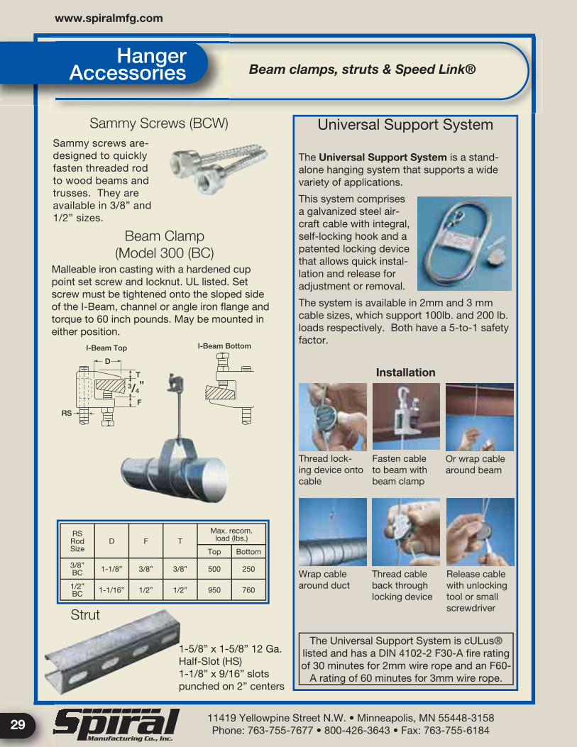
3/8” BC 1-1/8” 3/8” 3/8” 500 250
1/2” BC 1-1/16” 1/2” 1/2” 950 760
Malleable iron casting with a hardened cup point set screw and locknut. UL listed. Set screw must be tightened onto the sloped side of the I-Beam, channel or angle iron fl ange and torque to 60 inch pounds. May be mounted in either position.
The Universal Support System is a stand-alone hanging system that supports a wide variety of applications.
This system comprises a galvanized steel air-craft cable with integral, self-locking hook and a patented locking device that allows quick instal-lation and release for adjustment or removal.
The system is available in 2mm and 3 mm cable sizes, which support 100lb. and 200 lb. loads respectively. Both have a 5-to-1 safety factor.
Thread lock-ing device onto cable
Fasten cable to beam with beam clamp
Or wrap cable around beam
RS
D
T
F
3/4”
I-Beam Top I-Beam Bottom
1-5/8” x 1-5/8” 12 Ga.Half-Slot (HS)1-1/8” x 9/16” slotspunched on 2” centers
Wrap cable around duct
Thread cable back through locking device
Release cable with unlocking tool or small screwdriver
Installation
Sammy Screws (BCW)Sammy screws are-designed to quickly fasten threaded rod to wood beams and trusses. They are available in 3/8” and 1/2” sizes.
Beam Clamp(Model 300 (BC)
Strut
Universal Support System
The Universal Support System is cULus® listed and has a DIN 4102-2 F30-A fi re rating of 30 minutes for 2mm wire rope and an F60-
A rating of 60 minutes for 3mm wire rope.

30
Size A B C D E R Wgt.Lbs
6” 9 51/2 23/4 63/4 4 3 11/2
8” 9 55/8 21/4 63/4 4 4 13/4
10” 9 53/4 23/8 63/4 4 5 2
12” 111/8 63/8 23/8 91/8 41/2 6 21/2
14” 111/4 61/2 23/8 91/8 41/2 7 3
16” 111/4 61/2 21/4 91/8 41/2 8 3
Size A B C D E Wgt.Lbs
41/2”x9” 113/8 63/4 15/8 91/4 43/4 21/2
9” x 18” 20 111/8 15/8 18 9 518” x 18” 21 21 15/8 18 18 16
Size A B C D E RWgt.Lbs
4” 6 31/2 17/8 33/4 23/8 2 1/2
6” 87/8 53/8 21/2 6 37/8 3 1
8” 87/8 55/8 21/6 61/4 4 4 11/2
10” 87/8 55/8 2 61/4 4 5 11/2
12” 83/4 61/2 13/4 61/4 4 6 11/2
14” 111/8 61/2 2 81/2 41/2 7 21/4
16” 11 61/2 13/4 81/2 41/2 8 21/4
18” 11 61/2 13/4 81/2 41/2 9 21/4
20” 11 61/2 13/4 81/2 41/2 10 21/2
22” 11 61/2 13/4 81/2 41/2 11 21/2
24” 11 61/2 13/4 81/2 41/2 12 21/2
Gasket(Hinged Only)Typ.
AD
E
RB
C
A D
E
B C
Opening
Opening
Opening
Opening
Cover
5/32” Dia. Mtg.hole typical
Mountinglip
B
AHinge
P = pipe size
Mountingfl ange
Over Centerclasp
3/4” x 1/8”gasket
Aluminum, Contoured and Hinged, Clean-Outs & Access Doors
Aluminum Contoured Hinged
Aluminum Flat Hinged
Aluminum Contoured – (removable cover)
Galvanized Access Door (Contoured or Flat)
Clean-Outs

www.spiralmfg.com
11419 Yellowpine Street N.W. • Minneapolis, MN 55448-3158Phone: 763-755-7677 • 800-426-3643 • Fax: 763-755-618431
Size A B D E G H Wgt.Lbs
3” 3 4 5 3/4 4 1/2 7/8 2 1/4 .625
4” 4 4 1/2 7 5 1/2 1 2 1/2 .75
5” 5 5 3/8 8 3/4 6 1/2 1 1/8 2 1/2 1.0
6” 6 7 10 1/4 7 1/2 1 2 3/4 1.75
7” 7 7 1/2 11 3/4 8 1/2 1 2 5/8 2.25
8” 8 7 3/4 13 9 3/4 1 2 5/8 2.75
9” 9 8 1/2 16 11 1/4 1 2 5/8 3.25
10” 10 9 16 3/4 12 1 1/8 3 4.0
11” 11 9 3/4 19 1/2 13 1 1/2 3 1/2 4.75
12” 12 10 19 3/4 14 1 1/8 3 5.5
14” 14 11 1/2 25 16 1/2 2 4 1/8 8.5
16” 16 12 3/8 26 3/4 18 1/2 2 4 1/8 10.25
18” 18 23 3/8 31 1/2 21 1/8 2 4 7/8 11.0
C
D
E
F
E H
G G
D
AB
A
B
LockScrew
Closed
Size
Open
LockScrew
Closed
Open
Size
* See side view of Half-Gate for “G” and “H” Dimensions.Stainless steel and larger sizes available upon request.Cast aluminum body with galvanized steel sliding door standard.
Larger sizes available upon request.
Blast Gates Cast Aluminum Full Gates & Half-Gates
Full Gates (Cast Aluminum)
Half-Gates (Cast Aluminum)
Size A B C D E F G H Wgt.Lbs
2” 2 5/16 4 1/2 1 3/4 4 1/2 3 5/8 2 3/4 1 7/8 0.5
3” 2 13/16 5 5/8 1 11/16 5 7/8 4 2 1/2 3/4 1 7/8 1
4” 3 13/16 6 7/8 2 3/8 7 9/16 5 3 7/16 3/4 1 7/8 1
5” 4 3/4 8 3 9 1/2 6 4 1/2 7/8 2 1/8 1.5
6” 5 9/16 10 3 1/4 11 1/4 7 5 7/16 7/8 2 1/8 2
7” 6 13/16 11 1/4 3 3/4 11 7/8 8 6 7/16 1 1/16 2 1/2 2.5
8” 7 13/16 12 5/8 4 1/2 14 1/4 9 5/8 7 7/16 1 1/2 4 3.5
9” 8 15/16 13 1/2 5 3/8 16 10 1/2 8 1/2 1 7/8 3 1/2 5
10” 9 13/16 14 3/8 5 11/32 17 11 3/8 9 9/16 1 1/2 3 3/4 5.5
11” 10 3/4 15 1/4 6 19 1/2 12 1/2 10 3/8 1 7/8 3 1/2 7
12” 11 13/16 16 1/4 6 3/4 20 5/8 13 1/4 11 9/16 1 1/2 3 5/8 7
14” 13 11/16 18 15/16 7 7/32 23 1/8 15 3/4 13 7/16 1 7/8 4 3/8 13
16” 15 11/16 21 1/4 8 9/16 27 17 7/8 15 7/16 1 7/8 4 3/8 16.5
18” 17 21/32 32 9/16 10 11/16 30 9/16 20 1/8 17 7/16 3 7 30
20” 19 11/16 34 11 3/16 33 5/8 22 1/4 19 7/16 3 7 1/8 35
22” 21 27/32 34 12 35 7/16 24 1/2 21 15/32 3 7 1/8 39.5
24” 23 13/16 34 13 49 7/16 26 1/2 23 7/16 3 7 1/8 52.5

32
Dia. I JWgt.Lbs
3” 10.28” 7.28” 1.5
4” 12.28” 8.28” 1.75
5” 14.28” 9.28” 2.5
6” 16.28” 10.28” 3.25
7” 18.28” 11.28” 3.75
8” 20.28” 12.28” 5.25
9” 22.28” 13.28” 6.25
10” 24.28” 14.28” 7.5
11” 26.28” 15.28” 8
12” 27.28” 15.28” 9.25
14”Call Factory
16”
Table 32-1: Air Gate Electrical Data
Table 32-2: Air Gate Size Data
A unique, electrically controlled, compressed air actuated blast gate. Mount them in even the remotest areas, and let them work for you. The operating slide design is encapsulated in a rigid cast aluminum frame and is powered by a patented “fl oating” piston/cylinder assembly designed for trouble free operation regardless of velocity pressures in the air handling system. Operates in any position and adapts to pipe or fi ttings from 3” to 16”. Operating air pressure from 40 to 150 PSI. Factory tested and ready to install.
Our series 83 Volume dampers are made of 20 gauge galvanized steel, utilizing heavy guage plated steel quadrants, designed with excellent handle action as well as quick wing nut adjustment for locking the damper. The frame is marked to show the exact position of the damper. It uses a 3/8” square end bearing in conjunction with a 3/8” spring lock pin adjacent to it. Body length equals diameter plus 4”(L=D + 4).
Our series 78 Double Quadrant Damper is designed for quick installation in the fi eld and lower air pressure. This damper utilizes two fully retractable threaded spring bearings, one washer with pointer handle, and a 5/16-18 wingnut.
See photo on page 49
Larger sizes available upon request.
Air Supply
Demand ResponseCenter with FixedFlow Restrictor
Air lines
Body
RaisedFace Collar
Slide
Air Cylinder
Series 83
Series 78
JI
Air Gates & Control Dampers Blast Gates
Dia.Power
Air Gates (Cast Aluminum with Stainless Steel Cylinder)
Control Dampers

www.spiralmfg.com
11419 Yellowpine Street N.W. • Minneapolis, MN 55448-3158Phone: 763-755-7677 • 800-426-3643 • Fax: 763-755-618433
Warning: To reduce the risk of static discharge igniting sus-pended particulates, the fl ex hose helix wire must be grounded to both the duct system and the machine as shown above.
InsideDimension
(inches)
Approx.Wgt.
(lbs./ft.)
MinimumCenterline
Bend Radius(inches)
Com-pression
Ratio
MaximumRecom-mendedNegative Pressure(in./Hg)
MaximumRecom-mendedPositivePressure
(psi)
2 .19 1.4 5:1 29 30
2.5 .29 1.4 5:1 19 30
3 .3 1.8 5.5:1 29 30
4 .46 2.7 6:1 24 22
5 .56 3.4 5.5:1 13 18
6 .66 3.8 6.5:1 8 15
7 .73 4.2 6.5:1 8 10
8 .65 5.2 6.5:1 2 7
10 1.1 6 6.5:1 2 7
12 1.3 7 6.5:1 1.7 6
14 1.5 8.4 6.5:1 1.1 5
16 1.7 9.6 6.5:1 .7 4.6
18 1.9 11 6.5:1 .5 4.1
Note: Technical data based on 2 ft. straight lengths of hose @ 72° F.
Table 33-1: Flexible Hose Properties
• Construction: Light duty clear polyurethane wall hose construction reinforced with a spring steel wire helix.• Product Features: • Excellent compressibility • Cut, gouge, and chemical resistant • Effi cient fl ow characteristics • Designed for wide temperature ranges • Maximum fl exibility and abrasion resistance• Applications: Recommended for industrial air movement, fume control, and dust collection applications.• Temperature Range: -65° F to 225° F• Diameter Range (Inches I.D.): 2”-18” (Available to 24”) • Standard Lengths: 10, 15, and 25 Feet• I.D. Tolerances (Inches): Up to 8”: -0.00 to +0.125; 8” and over: -0.00 to +0.250 Inch• End Finish: Plain Cut• Standard Color: Standard LD color: clear Standard HD color: black
Flexible clear polyurethane hose is tough and du-rable, and suitabe for a wide variety of appiications.
See clamps on next page.
Typical machine application
Flx-Thane LD (4” and 12” shown)
Flexible Hose Cross-Section
Flexible Hose Clear Clear Polyurethane Hose & Fittings
Flexible Clear Polyurethane Hose (LD)
Hose Coupling
HD Flex HoseDisconnect
J-LockCoupling
Strip polyurethane cover from helix wire and fasten with sheet metal screw through clamp and into duct and machine collar.

34
No. Range
02HC 113/16 - 2 3/4˝
03HC 2 9/16 - 3 1/2˝
04HC 31/2 -51/2˝
05HC 41/2 - 61/2˝
06HC 53/4 - 73/4˝
07HC 61/2 - 81/2˝
08HC 2 - 10˝
10HC 91/2 - 111/2˝
12HC 11 - 13˝
14HC 12 1/2 - 141/2˝
16HC 153/8 - 173/8˝
18HC 18 - 20˝
Housing 301Stainless Steel
Screws5/16˝ Hex Hd.StainlessSteel
Band201/301StainlessSteel
Band Thickness.021/026 inches
Band Width.05 Inches
Diam.
Range
1.2˝Max.
Table 34-1:Hose Clamp Sizes
Bridge clamps provide a tight seal on right-hand (standard) spiral wire fl ex hose. Band and housing are Type 301 stainless steel. Band is 1/2˝ wide and 0.025˝ thick. Screw is Type 305 stainless.
Note: To determine the spiral direction of your hose, look at the end of the hose. If the spiral goes away from you in a clockwise direction, then the hose has a right-hand spiral.
InsideDiameter(inches)
MinimumInside Throat
Radius(inches)
Approx.Weight Per
Foot(lbs.)
2” 6.34 .70
3” 9.75 1.02
4” 12.00 1.38
5” 16.25 1.70
6” 19.50 2.00
7” 22.75 2.33
Table 34-2: U100 .010”- .012” strip thickess
InsideDiameter(inches)
MinimumInside Throat
Radius(inches)
Approx.Weight Per
Foot(lbs.)
8” 30.00 4.65
9” 36.00 5.22
10” 40.00 5.78
12” 48.00 6.91
Table 34-3: U120 .018”- .020” strip thickess
Flexible Steel Hose & Hose Clamps Flexible Hose
Flexible steel hose is strip-wound interlocked and made from hot-dipped galvanized carbon steel. There are two different gauge thicknesses to choose from, depending on the severity of service. It can be twisted without unraveling. Steel fl ex is rated to 788° F. Spiral Manufacturing suggests that operating temperature not exceed 400° F. It is sold fully extended and may be less than specifi ed length if compressed.
From fully collapsed, tubing can be extended 2.5’’ per foot under a tension load of 25-lbs. minimum to 45-lbs. maximum. Install in systems in semicompressed condition, midway between fully extended and fully compressed.
Galvanized steel all metal suction and blower hose for dust and fume collection. An excellent choice for wood shop molders.
Flexible Steel Hose
Hose Clamps
Bridge Clamps
For clear polyurethane and black heavy duty (HD) fl exible hose only


![[single]LM flange Flange... · Duct Flange Profile Gasket-120-130-140 Flange Corner J2 J3 J4 J5 J6-20-30-40 S3/4 S5 Rating Provides for rapid assembly of cross joints Available in](https://static.fdocuments.in/doc/165x107/5f1d498ff2384b78bb621806/singlelm-flange-duct-flange-profile-gasket-120-130-140-flange-corner-j2-j3.jpg)