Installation, Setup and Operating Instructions v2.14
35
PC-VET WIRELESS ECG & TEMPERATURE MONITOR Installation, Setup and Operating Instructions v2.14 Vmed 2 Installation, Setup and Operating Instructions v. 2.14 PC-Vet Wireless ECG & Temperature Monitor © Vmed Technology 16149 Redmond Way • Suite 108 Redmond, WA 98052 USA Phone 425 497-9149 • Fax 425 497-0260
Transcript of Installation, Setup and Operating Instructions v2.14

PC-VET WIRELESS ECG & TEMPERATURE MONITOR
Installation, Setup and Operating Instructions v2.14
Vmed
2
Installation, Setup and Operating Instructions v. 2.14
PC-Vet Wireless ECG & Temperature Monitor
© Vmed Technology 16149 Redmond Way • Suite 108
Redmond, WA 98052 USA Phone 425 497-9149 • Fax 425 497-0260

PRECAUTIONS
DO NOT PLUG PC-VET SENSORS INTO ANY OTHER EQUIPMENT OR INTO AC LINE RECEPTICALES
PC-VET IS NOT REGISTERED WITH THE FDA FOR HUMAN USE.
Do not use in the presence of flammable anesthetics.
Do not immerse the PC-Vet, sensors or cables in water or other fluids. Avoid spilling any fluids on the PC-Vet or accessories. Review Service and Maintenance Chapter for proper cleaning procedures.
Do not gas sterilize or autoclave the PC-Vet or sensors.
Do not disassemble. The PC-Vet contains no operator serviceable components.
Electrical Interference: Strong electromagnetic or radio frequency interference (RFI) may affect the performance of all ECG equipment including the PC-Vet. RFI may result in distorted ECG signals. Do not operate near electro-cautery, diathermy equipment, or cellular phones. Radio frequency cautery equipment does not interfere with the PC-Vet.
CAUTION: Conductive parts such as electrodes and associated connectors and leads, including the neutral electrode, should not contact other conductive parts including ground when using the PC-Vet.
Ensure that electrodes are connected only to the patient and do not touch any other conductive part or equipment to prevent possible shock to patient from leakage current.
Avoid cable and connector damage by taking care when connecting and disconnecting sensors and leads from the PC-Vet. Grasp plug, not the cable and pull straight out and push straight in.
Do not pull clip leads from the patient without opening clip.
1
Table of Contents Table of Contents ...................................................................................................... 1 Chapter 1 Installation and Setup ............................................................................... 2
Installing the PC-Vet Application software............................................................................................. 2 Installing Bluetooth................................................................................................................................. 5 Bluetooth Installation and Discovery, Windows XP Service Pack 2 ................................................................. 7 Using the PC-Vet with Windows XP Service Pack 2.................................................................................... 11 Bluetooth Installation and Discovery; Computers Not Using Windows XP Service Pack 2................................ 12 Multiple Installations on Computers not using Windows XP Service Pack 2 ................................................... 24 Setup PC-Vet Defaults............................................................................................................................. 34 Setup Vet/Clinic Information...................................................................................................................... 36 Setup Patient Information......................................................................................................................... 37 Computer Video Resolution...................................................................................................................... 37
Chapter 2 Description.............................................................................................. 38
Hardware.............................................................................................................................................. 38 PC-Vet Keypad Controls.......................................................................................................................... 40 Application Software................................................................................................................................ 40 Windows Display..................................................................................................................................... 41 Sweep and Scale.................................................................................................................................... 42 Display Toolbar....................................................................................................................................... 42 Function Options..................................................................................................................................... 43
Chapter 3 Operating Instructions ............................................................................ 45
Preparation............................................................................................................................................. 45 Taking the ECG...................................................................................................................................... 46 Using Chest Probe............................................................................................................................... 47 Using Leg Clips .................................................................................................................................... 48 Using Esophageal Probe ......................................................................................................................... 48 Using Disposable Chest Electrodes..................................................................................................... 49
Chapter 4 Reviewer Program.................................................................................. 51
Description ............................................................................................................................................. 51 Modes of Operation.............................................................................................................................. 51 Using the Reviewer Program ............................................................................................................... 52
Chapter 5 Service and Maintenance ....................................................................... 61
Service and Support................................................................................................................................ 61 Troubleshooting...................................................................................................................................... 63
Appendix A Computer Requirements and Specifications........................................ 64
Computer Requirements...................................................................................................................... 64 Physical Specifications......................................................................................................................... 64 System Specifications .......................................................................................................................... 65
Appendix B Warranty .............................................................................................. 66

2
Chapter 1 Installation and Setup DO NOT INSTALL THE BELKIN BLUETOOTH SOFTWARE. Follow the Bluetooth instructions in this manual. Installing the PC-Vet Application software
1. Put the PC-Vet installation CD into the computer’s CD ROM drive. The Vmed PC-Vet installation program should automatically start and the window below should appear:
NOTE: In the software does not start automatically, click on the START icon in the lower left hand corner of the screen and select ‘Run’ from the menu. When the ‘Run’ dialog box appears, click the Browse button. A Windows Explorer window will appear that will allow you to navigate to your computer’s CD ROM device. The name of the CD should contain “PC-Vet”. Select this CD and double click on the file named “Setup” then click on “OK” in the ‘Run’ dialog box.
2. Click on “Next” to open the following window:
Chapter
1
3
3. Select “Yes”, which should cause the following window to appear::
NOTE: Vmed recommends that you use the default installation location. 4. Click “Next” and the following window should appear:

4
5. Select “Typical” and then click “Next”. The following window should appear:
6. Highlight “Accessories” and press “Next” to start the installation of the VetGard software from the CD-ROM device. Click Finish when the installation is complete.
5
Note: A Shortcut to the PC-Vet program has been placed on the windows desktop and on the Start menu.
7. Remove the PC-Vet Installation CD and turn off the PC-Vet by pressing and holding the ON/OFF key down until the device turns off.
Installing Bluetooth
IF YOUR COMPUTER HAS A PRE-INSTALLED BLUETOOTH DEVICE, DO NOT INSTALL THE BLUETOOTH ADAPTOR SOFTWARE. USE YOUR COMPUTER’S BLUETOOTH DEVICE.
IF YOUR COMPUTER USES THE WINDOWS XP OPERATING SYSTEM WITH SERVICE PACK 2 (SP2) INSTALLLED, DO NOT INSTALL THE BLUETOOTH ADAPTOR SOFTWARE. IT IS MUCH EASIER TO SET UP AND USE BLUETOOTH AND TO DISPLAY MULTIPLE MONITORS IF WINDOWS XP WITH SP2 IS USED. FOR THIS REASON, VMED RECOMMENDS USING A WINDOWS XP COMPUTER AND DOWNLOADING SERVICE PACK 2 AND THE LATEST CRITICAL UPDATES. IF YOU HAVE PREVIOUSLY INSTALLED THE BELKIN BLUETOOTH SOFTWARE, UN-INSTALL IT AND RE-BOOT YOUR COMPUTER. NOTE: If you are not using a Windows XP computer or you do not wish to update your XP system with SP2, refer to “Bluetooth Installation and Discovery, Computers Not Using Windows XP Service Pack 2” on page 12 of this manual.
STEP 1: Determine the version of your operating system
1. From the “START” button in the lower left hand corner of the screen, Click on “Control Panel” and then double click on “System”. A window similar to the one below should appear:

6
2. This window will tell you if your PC has Service Pack 2 installed. NOTE: If your operating system is not Windows XP with SP2, refer to page 11 for Bluetooth installation instructions.
STEP 2: Download Service Pack 2 for your Windows XP operating system.
3. Vmed recommends that Windows XP computers be upgraded to include Service Pack
2 since Bluetooth setup is much quicker. This requires internet access for the PC.
4. If you already have Service Pack 2 installed, proceed to STEP 3
5. If you are upgrading to Service Pack 2 and have previously installed Bluetooth software, select “Add or Remove Programs” in the Control Panel and remove this software.
6. Connect your PC to the internet
7. From the Start Menu select Windows Update and follow Microsoft’s instructions for
Service Pack 2 installation or “critical downloads.
8. After installation, restart your computer if required.
7
STEP 3
Bluetooth Installation and Discovery, Windows XP Service Pack 2
1. Plug the Bluetooth device (Dongle) into a USB port on your computer.
2. Windows should automatically detect the device. The computer should respond with an audio prompt and a balloon confirming detection of the device should appear in the lower right hand corner of the display. Close this balloon if it appears.
3. Double click the Bluetooth Devices icon on your desktop. NOTE: You
may also select “Bluetooth Devices” from the “Control Panel” or from the Windows Start Menu.
4. The following window will appear:
5. Click on the “Options” tab and make sure that each box is checked as below:

8
6. Click the “Devices” tab again and turn on your PC-Vet. Wait for the status indicator on the PC-Vet to turn yellow and then click the “Add” button. The following window should appear.
9
7. Click “Next” and your computer will search for the PC-Vet. When the PC-Vet is
discovered, a window like the one below will appear. The serial number following “Vmed” and beginning with EG will be the same as the serial number that is printed on the back label of the PC-Vet.
8. Highlight the identified PC-Vet and click “Next”, which will open the following window:

10
9. Select the “Don’t use a passkey” button and click “Next”. The window below will open:
10. Click “Finish” to conclude installation and discovery
11
Using the PC-Vet with Windows XP Service Pack 2
1. Power on the previously discovered PC-Vet. The STATUS light on the PC-Vet will turn red and then yellow. NOTE: Every device has to be discovered once. If you have never been through the discovery procedure with this particular device on this PC, do so before proceeding.
2. Start the PC-Vet application by double clicking the PC-Vet icon on the desktop.
3. The window below will open over the PC-Vet display screen:
NOTE: If you have discovered multiple PC-Vet monitors, the device last discovered or connected to your computer will appear in the text box in the above window. Press the “down” arrow to view the other devices, highlight the one you want to use and press “Connect” As many as eight PC-Vet devices can be connected to a computer at one time. The practical limitation, however, is the size of the display and the computing power of your computer. To use multiple devices, go to step #1 and repeat the discovery process for each. The Vmed software automatically selects the COM Port if Windows XP with SP2 is installed. The appropriate selection will be made automatically as shown in ”Configure PC-Vet” window under the “Tools” button in the application software.

12
Bluetooth Installation and Discovery; Computers Not Using Windows XP Service Pack 2.
1. Install the Bluetooth software from the CD included with the adaptor and per
instructions with the Bluetooth adaptor. NOTE: Do not plug the Bluetooth adaptor into the USB port until prompted in the installation sequence. 2. After installation is complete, close all windows and re-boot your computer. 3. Double click the “My Bluetooth Places” icon on your desktop and the window below will open:
4. Make sure that all the boxes in the window above are checked and click NEXT. A window will appear for you to name your computer. Please do so and then click NEXT which will open the “Initial Bluetooth Configuration Wizard” screen.
5. Click NEXT and the window below will open:
13
6. Deselect all services EXCEPT Bluetooth Serial Port by clicking on the box to the left of the text describing each service and then select finish. NOTE: Be sure to scroll down using the down arrow to ensure that all other boxes are NOT checked.
7. Click “Finish” and when the next window opens click SKIP and close all windows.

14
Set up of the Bluetooth Adaptor
1. The Bluetooth installation procedure will place a “My Bluetooth Places” icon on the Windows desktop. Double click on this icon and the following window will appear:
2. Click on the “View or modify configuration” hyperlink at the left side of the window, alternatively select “Bluetooth” from the top menu and then select “Advanced Configuration”. The following window should appear:
15
3. Choose the “General” tab of the setup box, then choose a name for your computer and enter it into the computer name box. Select the computer type: Personal Computer or Laptop Computer.
4. Select the “Accessibility “ tab and the following window should appear:
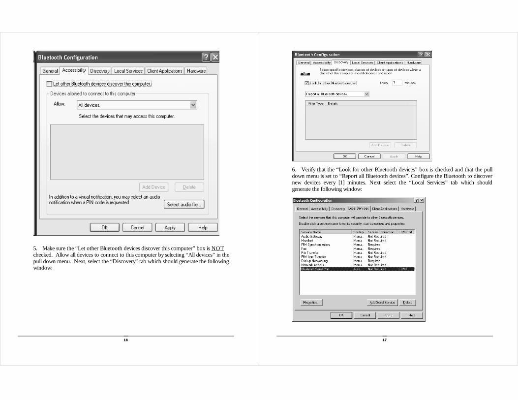
16
5. Make sure the “Let other Bluetooth devices discover this computer” box is NOT checked. Allow all devices to connect to this computer by selecting “All devices” in the pull down menu. Next, select the “Discovery” tab which should generate the following window:
17
6. Verify that the “Look for other Bluetooth devices” box is checked and that the pull down menu is set to “Report all Bluetooth devices”. Configure the Bluetooth to discover new devices every [1] minutes. Next select the “Local Services” tab which should generate the following window:

18
NOTE: The next part of the configuration sets up a COM port local to the computer which will host the actual Bluetooth COM port. In the example shown above COM7 was chosen by the Bluetooth software as the Bluetooth drivers were installed. The actual COM port number displayed on your particular PC-Vet may be different. This COM port number is NOT the one that is used by the PC-Vet application but is only an internal host for the COM port that will be used. Even though it is not directly used by the Vmed software. It is important that this host COM port be configured properly
7. Select the Bluetooth Serial Port which will highlight the text as shown above. If the Secure connection column of this item says anything other than “Not Required”, click on the “Properties” button which will bring up the following window:
8. Verify that the “Secure Connection” box is NOT checked. If changes need to be made, un-check the “Secure Connection” box and then click “Apply” followed by “OK” which should cause the Bluetooth Serial Port item to be configured to read “Not Required” in the “Secure Connection” column of the Bluetooth Configuration window.
19
THIS STEP IS CRITICAL TO PROPER OPERATION
9. In the Bluetooth configuration window select the “Client Applications” tab to open the following window:
Note: This part of the configuration deals with setting up the actual COM port used by the PC-Vet software. It is very similar to the setup for “Local Service” except now the COM port number will represent the actual COM port used to communicate to the PC-Vet. In the example shown above, COM5 was chosen by the Bluetooth software when the drivers were installed. The actual COM port number displayed on your particular PC may be different. If this is the very first time this window has been opened no COM port number will appear until “Properties” is clicked on.
10. Click on the Bluetooth Serial port which will highlight the text as shown above. If the Secure connection column of this item says anything other than “Not Required” or no COM port number has been assigned to the Bluetooth Serial Port, then click on the “Properties” button which will again bring up the following window:

20
11. Vmed recommends that the port be renamed “Bluetooth COMX” where X is the COM port number shown in the COM port box. Verify that the “Secure Connection” box is NOT checked. Click on “Apply” followed by “OK” which will configure the Bluetooth Serial Port to read “Not Required” in the “Secure Connection” column of the Bluetooth Configuration window and the new comport number will also appear.
NOTE: This step is critical to the proper operation of the PC-Vet. Write down this comport number (In this case, COM 5). It will be used later to configure the PC-Vet for connection to your computer.
12. Click “Apply” and “OK” in the above window then close the “My Bluetooth Places” Window.
21
Bluetooth Discovery
1. Bluetooth Discovery will be less confusing to setup when starting from a point of “No devices in range.” As a starting point turn OFF all Bluetooth devices within 150 meters. This includes other PC’s in the realm that have Bluetooth devices.
2. Double click the “My Bluetooth Places” icon on the desktop and the window below
will open:
3. Click on the “View devices in range” on the left side menu of the box or alternatively select the Bluetooth pull down menu and select “Search for devices”. This should cause the Bluetooth device to search for any devices in range. None should be found and the following window should be displayed:

22
4. Turn on the PC-Vet monitor by depressing and releasing the red ON/OFF power switch. The PC-Vet STATUS indicator will turn from red to yellow. Press the “OK” button in window above. Click on the “View devices in range” text to the left side of the box or alternatively select the Bluetooth pull down menu and select “Search for devices”. This should again cause the Bluetooth device to search for any devices in range. This time the window shown below should be displayed:
Note: If the battery level in the PC-Vet is low, the Replace Battery indicator will blink red. If the battery is critically low the indicator will be steady red. Do not proceed until the batteries have been replaced. In order to save power, the PC-Vet will turn itself off after 3 minutes of inactivity.
23
Note: Should this view not be seen, click on the right most icon (just under the word Help) on the toolbar and select ‘Details’ view. The text that appears under device name should be Vmed-ETXXXX, where XXXX is the unique I.D. number pre-programmed into each PC-Vet at manufacture. This number is stamped on the back label of each PC-Vet.
5. Double click on the Vmed ETXXXX icon to discover services available. 6. Right click on the Vmed ETXXXX text; this will bring up a menu of possible selections. Select “Connect COM0” which should cause the following window to appear:
Note: The icon will now be green in color and the word “Connected” should appear. The PC-Vet I.D. number will also appear near the logo. The “Status” light on the PC-Vet will also blink green.
Discovery is now complete. The computer should remember the connection of a particular PC-Vet to a particular COM port. Exit the Window and turn off the PC-Vet.

24
Multiple Installations on Computers not using Windows XP Service Pack 2
Several wireless monitors may be installed on one computer however each new monitor being displayed must be rediscovered each time. See the “Discovery” instructions in Chapter
1. Double click on the “My Bluetooth Places” shortcut located on the computers desktop. Within a few seconds this should cause the following window to appear:
2. Click on the “View or modify configuration” text to the left side of the box. The following screen should appear.
25
3. Select the “Client Applications” tab as shown and then click on the “Add COM port” button in the lower right hand side of the box. The following screen should appear.

26
4. Verify that the “Secure Connection” box is NOT checked. An additional COM Port
can be chosen from a pull down menu. In this case, the next available COM Port is COM10. Click on “Apply” followed by “OK”
Note: Up to four serial ports can be added in this manner; for the purpose of this document only one is added. The COM port numbers available may be different on your particular PC. They are a function of your PC’s hardware and software configuration. In this case COM5 and COM10 are available. For your PC these numbers may be different.
5. The window shown above should now appear listing the 2 available serial ports. 6. Turn on both PC-Vet devices and wait for the Status indicators on both devices to
turn from red to amber. Then view devices in range. The results should look similar to that below. In this case a PC-Vet with an ID of 0018 and one with an ID of 0047 have been discovered. The ID number will match the one stamped on the back label of your particular PC-Vet. Each PC-Vet has a unique ID number which will undoubtedly be different than the ones shown in this example
27
7. Turn one device off and then view devices in range. The results should look similar to that below. In this case the PC-Vet with an ID of 0047 has been turned off.
8. Double click on the icon and then double click again to discover the device the
screen shown below should appear:

28
9. The PC-Vet with an ID of 0018 has now been assigned to COM5. Turn the PC-Vet off and then on again. Wait for the status indicator to turn amber and double click on the PC-Vet desktop icon.
VetGard v2.12.lnk
29
10. Select “File” on the toolbar above and click on the “Connect PC-Vet” text to
remove the check mark. This will allow the “Tools” menu to become active.
11. Select “Tools” at the top of the screen, click “Configure PC-Vet” and the following screen will appear:

30
12. Verify that the COM port number is what you have previously determined it should be, change it if necessary and then select “OK”
13. Select “File” and again click on the “Connect PC-Vet” text to replace the check
mark. This will again allow the PC-Vet to connect to your computer.
14. Within a minute or so the PC-Vet should connect on the designated COM port and the status indicator should be green.
15. Leave this PC-Vet running, turn on the second PC-Vet and wait for the Status
indicator to turn amber and then return to the Bluetooth discovery window and search for devices. The screen should look similar to the one shown below:
31
16. Double click on the icon and then double click again to discover the device the screen shown below should appear:

32
17. The PC-Vet with an ID of 0047 has now been assigned to COM10. Turn the PC-Vet
off and then on again. Wait for the status indicator to turn amber and again double click on the PC-Vet desktop icon.
PC-Vet v2.12.lnk
18. A second instance of the PC-Vet program should run. The following error box should appear because COM5 is in use by 0018. Click OK
19. Next select the “Tools” menu at the top of the screen and click “Configure PC-Vet ” and the following screen will open:
33
20. Verify that the COM port number is as previously determined, change if necessary and then select “OK”
21. Select the File menu and click “Connect PC-Vet”. Verify that a check mark is next to the “Connect PC-Vet” text.
22. Within a minute or so the PC-Vet should connect on the designated com port and
the PC-Vet should operate normally. The Status indicator should be green. Leave the PC-Vet running.
23. Your PC is now configured to communicate with two PC-Vets at once. To use either
device, turn on the PC-Vet you want to use and connect to the COM port that has been assigned to it.

34
Setup PC-Vet Defaults This section describes the procedure to change the default settings that will apply each time the PC-Vet program is opened. Feature default settings such as TONE, ALARM, ON/OFF, GRID, etc. may be overridden by clicking the applicable icon on the upper toolbar only if the PC-Vet is connected to your computer.
1. Double click the PC-Vet icon on your desktop. The following window will open:
2. Click File and remove the check mark from “Connect PC-Vet” option. 3. Click Tools and the following dialog box will open: NOTE: You must remove the “Connect to PC-Vet” check mark each time you want to use the “Tools” menu. Don’t forget to replace check mark before trying to connect to the PC-Vet.
35
Figure 1 PC-Vet default configuration screen.
4. The COM port is selected automatically if Windows XP (SP2) is being used.
5. Set the desired alarm and other defaults on this screen.
6. The default ECG notch filter, used to filter AC line interference, can be set here also. For Domestic use (North America) choose 60 Hz; for international use choose 50 Hz.
7. Select the desired Reviewer recording mode by placing a check mark in the appropriate selection. NOTE: The default recording mode for the PC-Vet is “Event initiated 30 second ECG and Event storage”
8. Click “OK” to save these settings. These settings will be remembered each time the program is run.
36
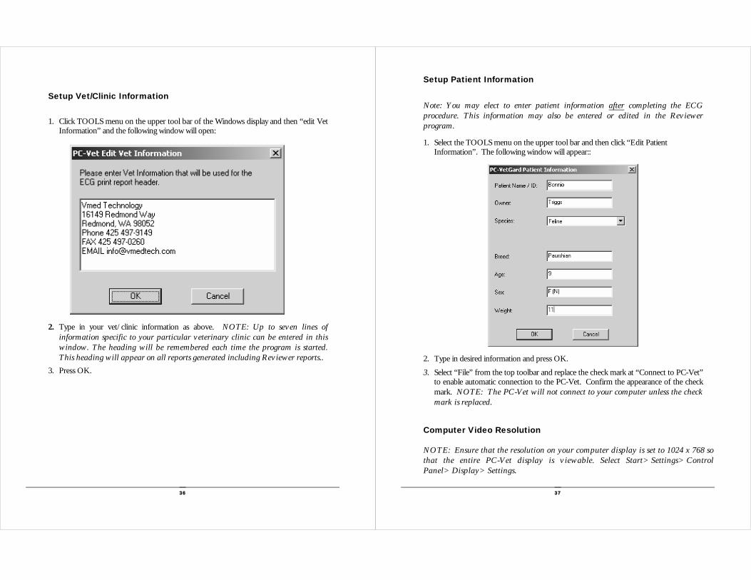
Setup Vet/Clinic Information
1. Click TOOLS menu on the upper tool bar of the Windows display and then “edit Vet Information” and the following window will open:
2. Type in your vet/clinic information as above. NOTE: Up to seven lines of information specific to your particular veterinary clinic can be entered in this window. The heading will be remembered each time the program is started. This heading will appear on all reports generated including Reviewer reports..
3. Press OK.
37
Setup Patient Information
Note: You may elect to enter patient information after completing the ECG procedure. This information may also be entered or edited in the Reviewer program.
1. Select the TOOLS menu on the upper tool bar and then click “Edit Patient Information”. The following window will appear::
2. Type in desired information and press OK.
3. Select “File” from the top toolbar and replace the check mark at “Connect to PC-Vet” to enable automatic connection to the PC-Vet. Confirm the appearance of the check mark. NOTE: The PC-Vet will not connect to your computer unless the check mark is replaced.
Computer Video Resolution NOTE: Ensure that the resolution on your computer display is set to 1024 x 768 so that the entire PC-Vet display is viewable. Select Start>Settings>Control Panel>Display>Settings.

38
Chapter 2 Description
Hardware The PC-Vet is a battery operated, Bluetooth enabled, wireless, ECG monitor equipped to provide Lead II information for the detection of rhythm and conduction abnormalities of the animal heart. ECG signals are detected using four sensors. Clip leads and disposable chest electrodes plug into the PC-Vet cable receptacle.
1. A chest probe with three built-in metallic electrodes placed so that when positioned over the heart, as described, accurate rate and rhythm information is derived.
2. A set of three clip electrodes that, when attached to the legs of the patient as described, provide Lead II information.
Note: Since it is not always possible to obtain an adequate signal using the chest probe, clip leads may be required when monitoring some patients. Clip leads can also be used to continuously monitor the ECG signal during surgery or for short term critical care monitoring.
Chapter
2
39
3. An optional internal esophageal probe is a convenient and superior method of monitoring ECG and temperature of the anesthetized patient. Three electrodes are affixed to a flexible plastic tube that is inserted into the esophagus and positioned over the heart with the distal electrode positioned behind the left ventricle and the second electrode behind the left atrium. The third electrode is ground.
4. An optional set of 3 leads with disposable electrode clips. This sensor is used for long term monitoring.
The PC-Vet is equipped with an integral wireless Bluetooth radio transmitter. Bluetooth enables the wireless transmission of information, including real-time ECG signals, between the PC-Vet and a Bluetooth enabled Windows based computer. The PC-Vet is designed to control computer and ECG functions without leaving the patient. Commands, including the print command, can be activated from the PC-Vet keypad, however data that must be entered with a keyboard such as clinic and patient information, cannot be entered from the key pad. Commands can be activated from the PC-Vet keypad or the PC-Vet window toolbar on the computer. However, the Windows display toolbar icons are active only if a wireless connection between the PC-Vet and the computer is established. Bluetooth operates at approximately 2.4 GHz. and steps up and down frequency constantly making the PC-Vet free of interference including the radio frequency interference found in hospital and clinic settings. Bluetooth transmissions are omni-directional and operate at low power and travel through walls and around corners to a radius of 50-100 ft. It is not necessary to aim the PC-Vet at the computer or printer to initiate the print function. The computer and/or printer can be in another room if desired. Any printer connected to your computer may be used, however the red ECG grid will print in black unless a color printer is used. Power is supplied by two AA alkaline batteries. Batteries will last for over 50 hours of continuous use. Battery life increases markedly by substituting long-life type AA batteries. Rechargeable AA batteries may also be used however a charger is not available through Vmed. Refer to the maintenance instructions at back of this manual for battery changing instructions.

40
PC-Vet Keypad Controls ON/OFF SWITCH: Press and release to turn ON; press and hold down to turn OFF. The PC-Vet will shut off automatically if a computer wireless connection is not established within three minutes.
UP/DOWN ARROWS: Scroll through the various menus available with the SELECT switch. Press the SELECT again after scrolling to the desired selection.
SELECT SWITCH: Connects to most icons on the display tool bar and allows the remote selection of options such as SPECIES, SWEEP SPEED, ALARMS, TONE, SCALE, GRID, etc.
EVENT MARK SWITCH: Places a red reference mark on the display and print copy to mark an event or point of interest.
STOP/START SWITCH: Stops and re-starts the ECG sweep
PRINT: Sends information on the screen to the printer that is connected to the computer. Print from moving trace or traces held with the STOP/START switch.
Application Software The Windows application program installed on your computer for the Software processing and display of real time ECG and temperature (when an esophageal probe is used) information. This software can be installed on multiple computers without limit and simultaneous instances of the program can be run subject to computer capability. Reviewer Program The Vmed Reviewer program is compatible with the Vmed PC-Vet ECG and Temperature Monitor and the VetGard Patient Monitor and allows the automatic storage of real-time ECG sweep and related information to the Reviewer program database. Refer to Chapter 4 for a complete description.
41
Windows Display
NOTE: To ensure that the entire screen is displayed, set computer screen resolution to 1024 X 768 by selecting START>SETTINGS>CONTROL PANEL>DISPLAY>SETTINGS tab.
Figure 2 Computer display of the PC-Vet information. Note: Temperature is only displayed when an esophageal probe is being used.

42
Sweep and Scale
Sweep: Sweep moves across display left to right at the selected sweep speed. Default sweep speed is 50 mm/sec. Sweep is blue if leads off or with poor electrode-patient contact and green with good electrode-patient contact. If the sweep is blue an ECG signal may be present, however a heart rate will not be displayed.
Vertical Scale: Vertical scale of display and print report measures signal amplitude. When the gain setting is 1, a signal amplitude of 1 mV has a vertical scale deflection of 10 mm by convention. Vertical scale deflection increases by a multiple of the gain.
CAUTION: Grid spacing does not change with change in gain setting. Use amplitude reference marker (1mV) to estimate amplitude of ECG signals on the screen when gain is other than 1.
Horizontal Scale: Time is measured on the horizontal scale and marked on the display and print report every second.
Display Toolbar
“R” WAVE MARKER RECORD CONTINUOUS ECG
SWEEP SPEED ALARM PATIENT ID
GRID GAIN BEEP TONE PRINT ABOUT
SILENCE ALARM
Figure 3 display toolbar
43
Function Options
1. Turn on the PC-Vet and establish connection to the computer. 2. Press the SELECT switch on the PC-Vet keypad and the following menu appears:
3. Use the UP/DOWN switches on the PC-Vet keypad to select the function and then the press the SELECT switch to choose the option. Repeat the process for each function. NOTE: These functions may also be selected from the PC-Vet toolbar
4. Press the EXIT to close the window after all choices are made.

44
NOTE: Refer to Chapter 1 to change default values for each function and for input of vet/clinic and patient information.
SELECT OPTIONS DEFAULT Silence Alarms Press to silence audio
alarm Keypad & Toolbar
Species Canine Gain 1 Feline Gain 1 Equine Gain 1 Other Gain 1
Sweep Rate 25 mm/sec 50 mm/sec 50 mm/sec 100 mm/sec
Gain 0.5: 55 mm/mV 1.0: 10 mm/mV 1.0: 10 mm/mV 2.0: 20 mm/mV 3.0: 30 mm/mV 4.0: 40 mm/mV
R-Wave Marker
ON OFF
OFF
Grid ON
OFF OFF Beat Tone ON
OFF OFF Record ECG Press for continuous
Reviewer recording Keypad & Toolbar
Alarms ON OFF OFF
Table 1 “Select” key options and factory default values
45
Chapter 3 Operating Instructions Preparation
PROCEED ONLY AFTER YOU HAVE SUCCESSFULLY INSTALLED THE SOFTWARE AND HAVE COMPLETED THE BLUETOOTH DISCOVERY PROCESS.
Note: If there is a Bluetooth icon at the lower right corner of your desktop, check that it is white in the center and not red. If the icon is red, the Bluetooth device is disabled. To correct this, right click on the icon and select “Start the Bluetooth Device”.
1. Plug the sensor of choice into the appropriate PC-Vet receptacle.
2. Double click the PC-Vet icon on your desktop to start the program. This will initiate the search process.
3. Turn on the PC-Vet by briefly depressing and releasing the red ON/OFF power switch on the keypad (Do not hold the power switch down). The STATUS light will turn red and then yellow.
4. Wait for the STATUS light to turn from yellow to green. The process may take as long as 30 seconds to complete the first time after initial discovery.
5. When the PC-Vet status light turns green, the notation in the STATUS box on the screen will change to “Connected” and the notation at the lower right corner of the screen will change to: “PC-Vet Remote Connected” on a green background.
NOTE: To preserve battery life, the PC-Vet will shut off automatically if connection to your computer is not established within 3 minutes.
Chapter
3

46
When connection is complete, the sweep appears on the display as a flat magenta colored line moving left to right at the selected sweep speed. Upon acquisition of a satisfactory signal, the waveform will appear and the trace will change to a color corresponding to the sensor:
Green: ECG Magenta: ECG leads off or poor signal quality White: (DIGITS ONLY): TEMPERATURE
NOTE: A magenta ECG sweep represents a leads off condition and may occur even if a waveform is present, however the computer will not recognize a valid ECG and the digital heart rate display will not appear. You should, in this case, reposition the sensor or clip leads until a green sweep appears.
Taking the ECG Important comments on ECG:
The PC-Vet obtains two types of clinical ECG information (l) rate and rhythm and (2) QRSP and T characteristics. For surgical and long term monitoring, rate and rhythm only is needed to monitor patient status since changes in heart rate or significant variation of the periodic interval of the beating heart may be indications of patient compromise. Accurate Rate and rhythm can be obtained by any of the available sensors provided with the PC-Vet, leg clips and the internal positioned esophageal probes being the most often used in surgery. For long term patient monitoring, leg clips or disposable chest electrodes may be used with the optional clip leads. Accurate diagnostic lead II ECG, on the other hand, requires information on both the rate and rhythm of the heart and evaluation of the ECG complexes themselves. Conductive abnormalities, for example are manifested by higher than normal R and S amplitude. For routine ECG and pre-surgical screening, the chest sensor is most convenient and is recommended for this application, however the method may produce inaccuracies in amplitude if the chest probe is not positioned at the correct angle to the heart. For this reason, whenever a beat characteristic or signal amplitude seems abnormal when using the chest sensor, a follow up trace should be taken using the leg clips to confirm the reading.
47
Using Chest Probe
1. Place the patient in the right lateral recumbent position and pull the front legs cranial.
2. Liberally apply alcohol or electrolyte solution to the left lateral chest wall where the electrodes will make contact. Position the chest probe over the heart, cable toward the head in the direction of the right shoulder, and press firmly enough that all three electrodes make good contact with the body wall.
3. Rotate the probe until the “R” amplitude is at its highest and a good tracing appears on the screen. If a good tracing is not obtained, re-saturate the chest wall with more electrolyte and reposition the chest probe. In some cases excess hair should be clipped. NOTE: To obtain a printable waveform, the trace must be green not magenta. Magenta signifies a leads-off situation even if a waveform is present.
4. Record the ECG until three good lines of tracing appear on the screen. NOTE: The three panels stacked vertically on the display represent a continuous trace with the earliest information being replaced by the current sweep. At the default chart speed of 50 mm/sec, the three panels represent 12 seconds of data.
5. Depress the Start/Stop button on the chest probe or on the PC-Vet keypad to stop the trace. Depress the Print button on the keypad to print this display and to automatically save it to the Reviewer program. You may also print directly from the moving trace by pressing the PRINT switch on the keypad.

48
Using Leg Clips
The three lead clips are color coded according to American Heart Association (AHA) standards. The following table provides the list of AHA color codes for Lead II connections modified to identify animal legs.
LEAD BIPOLAR LEAD & REFERENCE COLOR
II RF-Right Front Negative Electrode White
RH-Right Hind Reference Green
LH-Left Hind Positive Red
Note: For an accurate Lead II reading, each pair of legs must be parallel to one another but not touching. Use standing or right lateral recumbence.
Plug each clip lead wire into the appropriate receptacle of the matching color on the connecting cable yoke.
1. Plug the connecting cable into the PC-Vet receptacle
2. Place animal in the right lateral recumbent or standing position
3. Saturate the area where clips attach with alcohol or electrolyte
4. Connect leg clips according to the color coded designation stamped on the connecting cable. Connect two clips to the hind legs, Red to left hind and Green to right hind, on the posterior aspect of the leg just proximal to or distal to the point of the stifle. Connect the remaining clip, White to the right front leg on the anterior aspect of the leg just proximal to or distal to the elbow.
Using Esophageal Probe
Choose the right probe for the size animal. If the baseline tends to wonder or deviate from a straight line, the electrode spacing is too large and a probe with a shorter spacing should be used. If the ECG signal is intermittent, usually with respiration, the electrode diameter is too small for the animal and a probe with larger diameter electrodes should be use. NOTE: Do not try to evaluate ECG traces using the esophageal probe. The sweep is accurate for rate and rhythm information only.
1. Lay the probe on the animal simulating it being in the esophagus.
49
2. Place end of probe one finger width from the last rib.
3. Note the distance marked on the probe in cm at the nose.
4. Slide the probe into the esophagus until the distance marked at the animal’s nose is at the mouth.
5. Move probe cranial and caudal until the best ECG signal is
Using Disposable Chest Electrodes The clip leads provided with this optional sensor connect to the metal tabs on disposable infant pre-gelled electrodes. Disposable chest electrodes are best for long term, critical care situations when the animal is under or recovering from anesthesia. It may be necessary to shave excess hair.
1. Plug the three clip leads into the corresponding colored receptacle on the yoke cable. 2. Connect clips to each of three electrodes.
3. Prepare the electrode site by clipping excess hair.
4. Wet area with alcohol and wipe dry.
5. Remove electrode from the liner and place on the leg indicated by the color code on
the cable preferably above the hock and elbow. Electrodes may also be placed on the chest, over the heart and oriented to the Lead II axis: White on right chest toward right front leg, Red in the middle and Green on left chest toward the left back leg. NOTE: It is suggested that a protective bandage be applied over the electrodes to prevent the animal from dislodging or chewing off the electrode or lead. Accurate Lead II information is only available if electrodes or clips are attached to the patients’ legs.
6. Smooth down the electrodes with a circular motion. Avoid pressing on center of
electrode.

50
Printing and Storing Records
Once you have recorded a satisfactory ECG trace you may print the information in the 8 ½” x 11” report format shown below.
TO PRINT REPORT 1. From the PC-Vet keypad: Press Print, or… 2. from the display upper tool bar: Click the print icon, or…
3. From “File” choose print.
NOTE: Printing from the screen requires wireless connection between the PC-Vet and your computer. Printing from saved and recalled files does not require a wireless connection. 4. You may save reports to a PDF file by selecting” Acrobat PDF” or other PDF program in the “Print to” drop down box in the print dialog window.
Figure 4 PC-Vet print report [Note signal amplitude (1 mV) reference scale and time reference points on horizontal axis]. Temperature readout requires use of esophageal probe.
51
Reviewer Program Description The Vmed Reviewer program is included with each Vmed wireless monitoring product and is also available free to any interested person in order to facilitate ECG interpretation by third party consultants. The Reviewer program performs the following functions:
Provides a patient database where information recorded from Vmed wireless monitoring products may be stored automatically.
Allows archived ECG sweep, patient and episode data to be recalled for review, editing, measurement and printing.
Provides for the electronic measurement of ECG complexes Allows real-time playback of previously recorded ECG sweep data. Makes available, through the Help menu, a table of normal ECG measurements for cats and dogs and guidelines for measuring ECG complexes.
Provides an easy method of summarizing and storing ECG measurements, vital signs and diagnostic notes.
Provides and easy way of sending email transmission of stored reports. Automatically documents and stores vital signs every 5 minutes.
NOTE: At the present time, files cannot be integrated with practice management software programs. Check the Vmed website for future software updates that may make this possible.
Modes of Operation ECG and related data are stored automatically in one of three available modes. Record modes are selected in the PC-Vet Configuration window: 1. Continuous Event Recording (Typically used in surgery monitoring)
Records vital signs only on event (Print command, alarm activation, or change of record mode).
Does not record ECG sweep Records Vital signs every five minutes. NOTE: This is the default mode for the VetGard patient monitor
Chapter
4

52
2. Event Initiated ECG Sweep Recording (Typically used in ECG exams)
Vital signs and 30 second ECG sweep are recorded on event (Print command, alarm activation, change of record mode). NOTE: This is the factory default mode for the PC-Vet.
3. Continuous ECG Sweep Recording (Typically used in long-term monitoring)
Continuous recording of ECG sweep and event initiated vital signs for the life of the batteries (about 50 hours).
Activated by pressing the Record icon on the PC-Vet toolbar. (See Display toolbar on page 42) NOTE: This mode selection overrides and supersedes any previously selected mode.
Using the Reviewer Program
1. Click the Reviewer icon on the desktop and the Reviewer window will open: 2. Click “File” then “Patient episode on the upper toolbar and the window below will open:
3. Highlight the patient of interest and then the episode as above and press OK and the next screen will appear:
53
NOTE: Patients are filed alpha-numerically. If a patient is not pre-identified, patient files are stored numerically by year, month, day and time. Patient data can be entered prior to, during, or after the monitoring procedure and edited by using the Reviewer toolbar. Episodes are identified by date and time of the event.
NOTE: This screen summarizes the patient file for the episode selected along with cursor measurement of the QRS complex. The measurements selected have been dropped into the diagnostics notes and comments box. Note the red rubber band vector and the measurement crosshairs above.
Using the electronic cursor measurement feature:
1. First click on the complex you wish to measure in the “Measurements” box at the top of the screen. Note: For a description of each complex, click on the “Help” menu in the upper toolbar.

54
2. Next, left click the mouse at the beginning point of your measurement, then drag the mouse to the right and up if amplitude is to be included. Note the red rubber band in the above illustration. Place the blue crosshair at the end of the interval and the top of the amplitude and release the mouse button. The one step measurement will result in an interval and amplitude calculation if appropriate for that complex. NOTE: For best accuracy, increase the gain of the signal before beginning the measurement procedure.
3. Repeat the procedure in step 2 for each measurement.
4. Click the “Copy to Diagnostic Notes” box to drop your measurements into the diagnostics notes section of the report.
Upper Tool Bar Icons
NOTE: The first row contains the command buttons like any Windows toolbar. The “Tools” button deserves some comment, however. The “Tools” command includes the following options:
55
Manage Patient Episodes: Selecting this choice opens the screen below:
This screen allows you to remove unwanted patients and episodes. To delete a patient, highlight the patient and press the “Delete Patient” button. To delete an episode, highlight that episode and press the “Delete Episode” button. NOTE: to delete episodes, you must first highlight a patient.
Configure Vmed Reviewer Selecting this option opens the screen below:
NOTE: This window allows you to select the directory where patient files are stored. The default directory is “My Documents” You can also change the color of the printed report grid as well as the grid color in the Reviewer.
56
The second row of the upper toolbar displays the icons listed below. NOTE: Some of these icons are duplicates of commands that appear under the “File”,” Edit” and “View” menus.
Open Episode: Opens patient and episode window Save Episode: Saves the information on the window displayed Email Episode: Opens the Email window with the file as an attachment
NOTE: If your computer is equipped with MAPI capable email like Outlook or Outlook Express, you can email the report using this button. Otherwise, the appropriate file may be opened from the “My Documents”>”Vmed Episode” file. Select the patient and episode of interest and select “Send To”> “Email Recipient” or drag and drop the file directly into your email “Attachments box”.
Edit Clinic/Vet information: Opens Clinic/vet window for any changes
NOTE: The controls described below are only visible if you have selected an episode that includes an ECG sweep, otherwise these icons will be grayed out.
Change Sweep Speed: Select chart sweep speed in drop down window Change Gain Setting: Select desired ECG gain from drop down window. Again, it is best to increase the gain setting in order to obtain more accurate cursor measurements.
Add “R” Wave Markers: Places triangular marker over each “R” wave to help identify this complex.
Up/Down Arrows: Changes the position of QRS complex displayed in the sweep area and brackets the sweep to be printed. Use this control to show the entire sweep complex in the window before printing.
Episode time display: The time that the episode was recorded is displayed here.
Video Controls: for the real-time playback of recorded sweep and to stop, start and scroll the ECG record.
Print Command: Prints to any printer connected to the computer being used.
Question Mark: Displays the version of the your Reviewer program
57
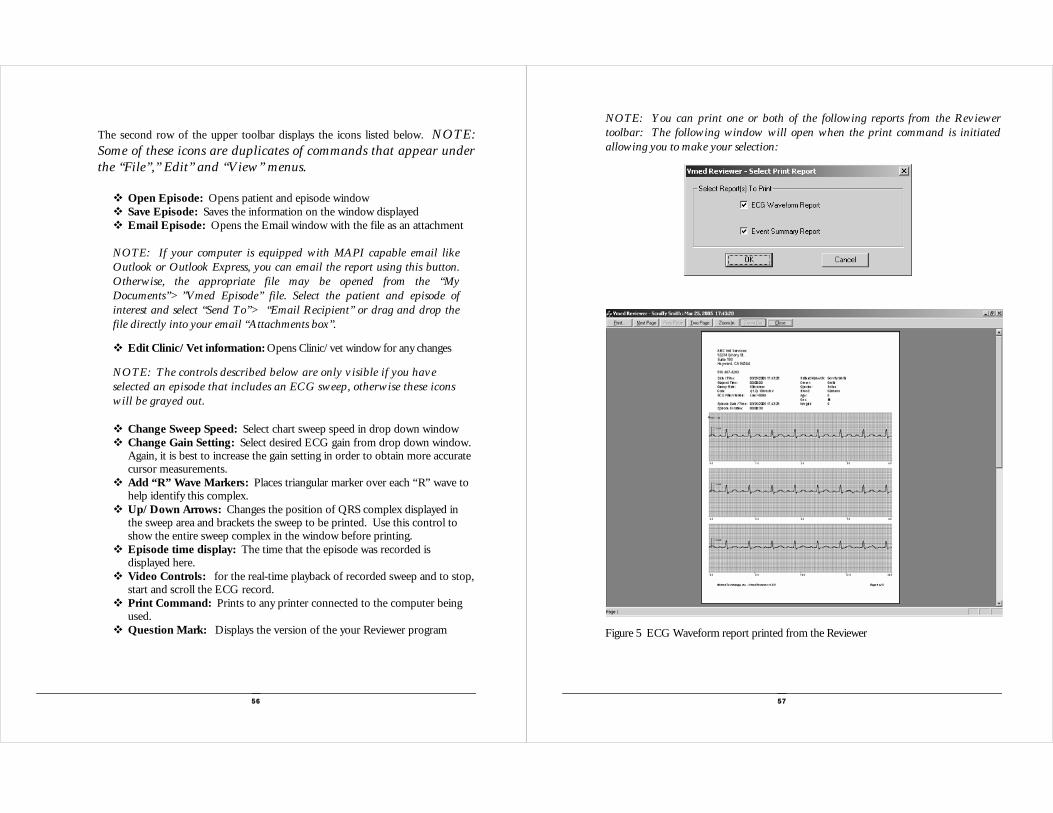
NOTE: You can print one or both of the following reports from the Reviewer toolbar: The following window will open when the print command is initiated allowing you to make your selection:
Figure 5 ECG Waveform report printed from the Reviewer

58
Figure 6 Event Summary Report includes vital signs, measurements and clinical comments.
NOTE: Selecting “Help” from the Reviewer upper toolbar allows you to open a window for assistance in defining and measuring ECG complexes and to display a table of normal measurements for feline and canine patients. These selections are shown below:
Figure 7 Instructions for measuring ECG complexes from the “Help” menu
59
Figure 8 Table of Normal ECG measurements for canine patients from the “Help” menu.

60
Figure 9 Table of Normal ECG measurements for feline patients from the “Help” menu
Information in Tables 7, 8 and 9 from Electrocardiography for the Small Animal Practitioner, Larry P. Tilley, DVM, Diplomate, ACVIM (Internal Medicine), Naomi L. Burtnick, MT (ASCP). “Made Easy Series”, Teton New Media.
61
Chapter 5 Service and Maintenance Service and Support If you purchased directly from Vmed: Phone: 800 926-9622 FAX: 424 497-0260 Email: [email protected] WEB: www.vmedtech.com If you purchased from DVM Solutions or your dealer: Phone: 866 373-9627 FAX: 830 438-7041 WEB: www.dvmsolutions.com
Cleaning
Clean the PC-Vet, sensors and cables by wiping surfaces with any of the following solutions:
• Soap and water • Alcohol or alcohol/disinfectant mixture • Peroxide solution
Precautions
Do not immerse or soak the PC-Vet or cables and sensors in any liquid Do not use petroleum based solvents Do not steam autoclave Do not gas sterilize the PC-Vet or sensors
Chapter
5

62
Maintenance There are no field serviceable components inside the PC-Vet. Opening the housing voids the warranty. Store the PC-Vet in the storage pouch when not in use.
Changing Batteries
To change the two AA batteries, press and slide open the battery compartment lid on the back of the PC-Vet housing. Batteries are best removed by slapping the bottom of the PC-Vet against the palm of the hand until the batteries are dislodged and fall into your hand as shown below. Note polarity when replacing batteries. Insure that each new battery makes proper spring contact and is pushed all the way into the bottom of the battery compartment.
Cable Connectors Sensor plugs should be inserted into the receptacle by pushing straight into the opening while grasping the plug. Do not remove by pulling on wire. Note the Vmed logo is on the top and the plug key is on the bottom. Troubleshooting Refer to the table on the next page to trace common problem areas.
63
Troubleshooting
SITUATION POSSIBLE CAUSE CORRECTIVE ACTION
Cannot make Bluetooth connection with computer.
Weak battery on PC-Vet Improper Bluetooth discovery. Bluetooth not enabled
Replace with two fresh AA batteries Re-initiate discovery procedure Enable Bluetooth on lower toolbar icon
Bluetooth connection has range <50ft.
Low Batteries Signal must pass through high attenuation barrier such as concrete floor/walls or heavy metal objects
Replace both batteries Clear signal path
Cannot acquire satisfactory ECG signal
Not enough electrolyte fluid used. Not making adequate skin contact Corroded electrodes. Broken or corroded lead wire, cable or plug. Bad cable connection
Re-apply electrolyte. Re-position electrodes and clip excessive hair. Replace electrodes. Replace lead wire or cable Remove and re-insert all plugs
Excessive noise in the ECG signal
Inappropriate filter selected. Poor electrode-skin contact. Excessive motion. GAIN set too high RFI or electromagnetic interference.
Change filter selection in the “Tools” drop down menu. Re-apply electrolyte and re-position electrodes. Reduce patient motion. Set GAIN to 1. Shut off electrical devices near PC-Vet
Lost wireless connection with computer
PC-Vet out of range of computer or behind signal attenuator. PC-Vet lost power Bluetooth device loose in USB port. Computer turned off or PC-Vet program closed
Move toward computer or clear attenuating obstacle. Check PC-Vet power on switch Check /Replace Batteries Check Bluetooth device/USB connection. Re-start PC-Vet program.

64
Appendix A Computer Requirements and Specifications Computer Requirements • >200 MHz. PC desktop, laptop or tablet computer
• Windows 98 SE, 2000, Me, XT or NT operating system (XT recommended)
• 32 MB RAM
• SVGA display, 256 colors, resolution set to 1024 X 768
• Spare USB 1.1 port
• CD Rom Drive
• 30 MB available hard disk space for PC-Vet program, plus approximately Kbytes per patient stored
• Windows supported printer
• MAPI compliant E-Mail system such as Microsoft Outlook or Outlook Express.
Physical Specifications
TYPE: Three lead ECG with integrated Bluetooth wireless module CONSTRUCTION: High impact ABS plastic with over-molded sides. DIMENSIONS OVERALL
LENGTH: 6.0” WIDTH: 3.75” THICKNESS: 1.1”
WEIGHT (WITH BATTERIES) 7.4 oz. CONTROLS: FLAT PANEL KEYPAD SWITCHES, TACTILE PUSH TYPE:
ON/OFF SELECT UP/DOWN ARROWS STOP/START EVENT MARK PRINT INDICATORS: STATUS LED REPLACE BATTERIES LED
CABLE CONNECTION: Circular mini-DIN, 6 pin. BATTERIES:
TYPE: AA Alkaline, Long life or rechargeable QUANTITY: 2 BATTERY LIFE: >50 hours continuous operation POWER CONSUMPTION:
PATIENT CABLE AND LEADS: 36” ZIP cable with three clips attached Three electrode chest probe with 32” cable and connector
Optional 3 receptacle yoke cable for patch-on electrodes
Appendix A
65
System Specifications
ECG GAIN/SENSITIVITY: 5, 10, 20, 30 mm/mV COMMON MODE REJECION: -70dBV CMRL SAFETY STANDARDS: IEC 601, AAMI EC-11 INPUT IMPEDANCE: 1 M Ohm INPUT DYNAMIC RANGE: 15 mV DC OFFSET CORRECTION: -0.5 Hz. A/D SAMPLING RATE: 500 Hz. SAMPLE RESOLUTION: 12 bit ECG SWEEP SPEED, SELECTABLE: 25, 50, 100 mm/sec. (Default: 50 mm/sec.) QRS DETECTION RANGE: >0.2 mV FILTERS:
PERMANENT: Pass Band: High pass: 70 Hz Low pass: 40 Hz USER SELECTABLE: Notch (AC line noise rejection): 50/60 Hz
ALARMS: HEART RATE: High/Low, selectable limits TEMPERATURE: Low limit selectable with auto step-down
FEATURES: ALARMS: ON/OFF TONE: ON/OFF GRID: ON/OFF ALARMS: ON/OFF R-WAVE DETECTOR: ON/OFF EVENT MARK: USER ACTIVATED
WIRELESS: Bluetooth Class I radio RANGE: 50-100 ft. in practice FREQUENCY: 2.4-2.4835 GHz OUTPUT POWER: 4 to 20 dBm PHYSICAL INTERFERANCE: USB UHCI/OHCI 1.1 compliant MANUFACTURER: Belkin Model F8T001or I/O Gear Model GBU-311
PC SYSTEM REQUIREMENTS: CPU: Windows compatible computer, 200MHz or > Memory: Min 256 MB, 512 MB recommended USB port: One available, USB 1.1 standard Operating Systems: Windows 98 SE, Me, 2000 or XP Audio: Any Windows audio hardware and speakers Video: 32 MB video RAM, 64 MB recommended. Resolution: 1024 x 768 Software Color Profiling: Disabled

66
Appendix B Warranty Vmed Technology warrants that the PC-Vet ECG monitor to be free of defects in material and workmanship for a period of TWO YEARS from the date of purchase by the original end user customer. ECG sensors including cables, lead wires and connectors sold with the PC-Vet or purchased as an optional accessory, are warranted for a period of SIX MONTHS from the date of original purchase. If in the judgment of Vmed Technology, the PC-Vet or accessories are proven to be defective during the warranty period, they will be repaired or replaced with no charge for parts or labor.
This warranty does not cover consumable supplies or products damaged by accident, abuse, or misuse or products altered or repaired by anyone other than Vmed Technology or its designated repair agents. OPENING THE PC-VET HOUSING WILL VOID THE WARRANTY.
This warranty is exclusive and is in lieu of all other warranties whether expressed or implied including warranties of merchantability and fitness for a particular purpose. The obligations under this warranty are limited to repair or replacement.
A return authorization number is required before returning any product for warranty or non-warranty repair. Products or parts shipped to Vmed for warranty service must be shipped prepaid and insured via a carrier that provides package tracking such as UPS or FedEx. Vmed will pay the return freight on products repaired under warranty.
Appendix B


![Seratio Blockchain whitepaper - Values Based Impact Interventions (21 Dec 2016) [v2.14]](https://static.fdocuments.in/doc/165x107/58ed5b691a28ab90718b45cf/seratio-blockchain-whitepaper-values-based-impact-interventions-21-dec-2016.jpg)