Installation & Service Instructions Puma 80, 80e &...
52
Part No. 27/18810 - 03 Puma 80 - G.C. No. 47 590 10 Puma 80e - G.C. No. 47 590 11 Puma Saver - G.C. No. 47 393 01 Installation & Service Instructions Puma 80, 80e & Saver Wall Mounted, Fanned, Room Sealed Combination Boiler THE GAS SAFETY (INSTALLATION AND USE) REGULATIONS 1994 (as amended). ‘‘ In your own interest, and that of safety, it is law that all gas appliances are installed by competent persons, in accordance with the above regulations. Failure to install appliances correctly could lead to prosecution.’’ The polythene bags used for packaging are a potential hazard to babies and young children and MUST BE DISPOSED OF IMMEDIATELY. LEAVE THESE INSTRUCTIONS WITH THE USER FOR USE ON FUTURE CALLS For Use With Natural Gas (G20) Only At 20mbar For Use in GB & IE IMPORTANT PLEASE READ THIS BOOK BEFORE INSTALLING, OPERATING OR SERVICING THIS APPLIANCE
Transcript of Installation & Service Instructions Puma 80, 80e &...

Part No. 27/18810 - 03Puma 80 - G.C. No. 47 590 10
Puma 80e - G.C. No. 47 590 11Puma Saver - G.C. No. 47 393 01
Installation & Service Instructions
Puma 80, 80e & Saver
Wall Mounted, Fanned, Room Sealed Combination Boiler
THE GAS SAFETY (INSTALLATION AND USE) REGULATIONS 1994 (as amended).
‘‘ In your own interest, and that of safety, it is law that all gas appliances are installed by competent persons, in accordancewith the above regulations. Failure to install appliances correctly could lead to prosecution.’’
The polythene bags used for packaging are a potential hazard to babies and young childrenand MUST BE DISPOSED OF IMMEDIATELY.
LEAVE THESE INSTRUCTIONS WITH THE USER FOR USE ON FUTURE CALLS
For Use With Natural Gas(G20) Only At 20mbarFor Use in GB & IE
IMPORTANTPLEASE READ THIS BOOKBEFORE INSTALLING,OPERATING OR SERVICINGTHIS APPLIANCE
Contents - Page 2Technical Data ............................................................... 3Introduction.................................................................... 4Optional Extras .............................................................. 5
1. Installation Requirements................................... 81.1 General Information..................................... 81.2 Location of Boiler......................................... 71.3 Flue Terminal and Ducting .......................... 101.4 Air Supply .................................................... 101.5 Guide to System Requirements .................. 111.6 Mains Water Feed C.H................................ 121.7 Installation to an Existing System ............... 121.8 Hard Water Areas ....................................... 121.9 Pump Performance Curve........................... 131.10 Electrical Supply.......................................... 141.11 Clearance Around the Appliance................. 15
2. Boiler Installation ................................................ 162.1 Unpacking ................................................... 162.2 Gas Connection........................................... 172.3 D.H.W Supply.............................................. 172.4 C.H. Supply ................................................. 172.5 Pressure Relief Valve.................................. 182.6 Wiring the Appliance ................................... 18
3. Commissioning.................................................... 193.1 Electrical Installation.................................... 193.2 Gas Installation............................................ 193.3 Initial Lighting .............................................. 203.4 Gas Pressure Adjustment ........................... 213.5 Products of Combustion Measurement ....... 223.6 D.H.W Flow Rate ........................................ 233.7 Central Heating ........................................... 233.8 Temperature Controls ................................. 233.9 Appliance Protection Devices...................... 233.10 Re-fit Outer Case ........................................ 243.11 Handing Over to the User............................ 24
4. Servicing .............................................................. 25
5. Routine Maintenance .......................................... 265.1 Remove the White Front Case.................... 265.2 Remove Base Panel.................................... 265.3 Remove the Air Box Covers ........................ 265.4 Remove the Fan Assembly ......................... 26
5.5 Remove the Flue Hood................................265.6 Remove the Combust. Cham.
Front Panel ..................................................265.7 To Inspect and Clean the Boiler...................265.8 To Remove the Burner.................................285.9 Gas Pressure Adjustment............................285.10 The Central Heating Sealed System ...........285.11 Other Components ......................................28
6. Component Replacement....................................306.1 Central Heating Overheat Thermostat.........316.2 Dom. H/Water Limit & Frost Thermostat......316.3 Sensor and Ignition Electrode......................316.4 Sensor and Ignition Leads ...........................316.5 Spark Ignition Lead......................................316.6 Thermocouple..............................................316.7 Burner ..........................................................326.8 Injectors .......................................................326.9 Gas Valve ....................................................326.10 Modulating Valve .........................................326.11 First Solenoid Valve.....................................326.12 Second Solenoid Valve................................326.13 Case Seal ....................................................326.14 Central Heating and Boiler Switch ...............356.15 Electronic Control Boards ............................356.16 Air Pressure Switch......................................366.17 Fan...............................................................366.18 Fan Seals.....................................................366.19 Temperature Sensor D.H.W and C.H..........366.20 Pressure Gauge...........................................366.21 Water Flow Switch D.H.W ...........................376.22 Microswitch (D.H.W Flow Switch)................376.23 Pump ...........................................................376.24 Diverter Valve ..............................................386.25 Expansion Vessel D.H.W ............................396.26 Expansion Vessel C.H.................................396.27 Heat Exchanger ...........................................406.28 Automatic Air Vent .......................................406.29 Pressure Relief Valve ..................................406.30 Water Pressure Switch ................................416.31 Transformer Assembly.................................416.32 Sight Glass with Securing Frame ................41
7. Schematic Diagrams - Permanent Pilot .........42/458. Schematic Diagrams - Electronic ..................46/499. Short List of Spares.........................................50/51
GAS SAFETY (INSTALLATION AND USE) REGULATIONS 1994. (As Amended)
The appliance must be installed and serviced by a competent person, in accordance with the above Regulations.
In the UK 'Corgi' Registered Installers (including the Regions of British Gas) undertake the work to a safe and satisfactorystandard.
Failure to install appliances correctly could lead to prosecution.
It is in your own interest, and that of safety, to ensure that the Regulations are complied with.
Technical Data - Page 3
Heat Input: Max. 30.0kW (102,350Btu/h)Range Rate (C.H. Only) 22.5kW (76,760Btu/h)Min. 14.4kW (49,130Btu/h)
Heat Output: Max 24.0kW (81,880Btu/h)Range Rate (C.H. Only) 17.2kW (58,680Btu/h)Min. 10.4kW (35,480Btu/h)
Gas Rate Full 2.86m³/hr 101ft³/hr
Inlet Pressure 20mbar (18 - 25mbar)Burner PressureMax. (Max. Setting on Gas Valve) 15.0mbar (6.0" w.g.)Range Rate (C.H. Only) 8.3mbar (3.3" w.g.)Minimum (Electronically Set) 3.5mbar (1.4" w.g.)
Classifications I2H, C12 & C32,IP20
Pilot Burner Bray AB 1920Main Burner Bray AB 24081M
Gas Control Valve: SIT Controls (80) Nova 825 (0.825.013)Inc. 2nd Solenoid Valve (0.007.406)Inc. Modulator - 28V. DC. (0.007.413)
SIT Controls (80e/Saver) Nova 827 (0.827.127)Inc. 1st Solenoid Valve (0.007.424)Inc. 2nd Solenoid Valve (0.007.406)Inc. Modulator - 28V. DC. (0.007.413)
Burner Injector 3 off
Electrical Supply 230V ~ 50HzFuse Rating - External 3A
Packed Weight 58.5kg (129lbs)
Water Content C.H. 1.85 litresGas Supply Connection 1/2" B.S.P.F. Gas CockInlet Connection D.H.W 15mm Compression Isolating ValveOutlet Connection D.H.W 15mm Copper PipeFlow Connection C.H. 22mm Compression Isolating ValveReturn Connection C.H. 22mm Compression Isolating ValveSafety Discharge Pipe 15mm Copper Pipe
C.H. Sealed SystemMaximum Operating Pressure 2.5bar 36.3lb/in²Minimum Operating Pressure 0.5bar 7.25lb/in²10 Litre Expansion Vessel. Pre-charge Pressure 1.0bar 14.5lb/in²Maximum Temperature Rise across the Boiler 30°CCentral Heating Flow Temperature Max. Load 79°C
Min. Load 85°CCentral Heating Return Temperature 68°C (Nominal)D.H.W Flow Rate 35°C Rise 9.8litres/minute 2.16gals/minD.H.W Flow Rate 45°C Rise 7.6litres/minute 1.67gals/minD.H.W Temperature: Max 65°C
Min 45°CD.H.W Max. Pressure 10.0bar 145.0lb/in²D.H.W Min. Operating Pressure (Dynamic) 1.0bar 14.5lb/in²D.H.W Expansion Vessel. Pre-charge Pressure 3.5bar 50.8lb/in²

Introduction - Page 4
Samples of the Puma combination boiler have beenexamined by Gastec, a Netherlands Notified Body. Therange is certified to comply with the essential requirementsof the Gas Appliance Directive 90/396/EEC, the Low VoltageDirective 72/23/EEC and shows compliance with the ElectroMagnetic Compatibility Directive 89/336/EEC and aretherefore permitted to carry the CE Mark.
The appliance has been tested and approved by the WRc asmeeting the requirements of G3 and L of the Buildingregulations and water Bylaws Scheme - Approved Products.
The Potterton Puma range of boilers are fully automatic, wallmounted, fan assisted, room sealed combination boilers,designed to operate on Natural Gas only. The range ofconsists of permanent pilot and electronic versions in both24 kW and 29 kW (100,000Btu/h) outputs.
The 80, 80e and Saver models adjust automatically toprovide central heating outputs between 24 kW (81,880Btu/h) and 10.4 kW (35,480 Btu/h) to suit the systemrequirements.
Domestic hot water has priority over the central heatingsystem and is generated instantaneously within theappliance.
The combination boilers are designed for use with fullypumped sealed system only. This has the advantage thatheader tanks and hot water storage cylinders are notrequired.
The range of horizontal and vertical flue systems with smallterminals simplify siting and installation.
They are supplied fully tested and assembled with acirculating pump, diverter valve, pressure gauge, pressurerelief valve, and expansion vessels.
The appliances have two completely separate heatingsystems embedded into a copper heat exchanger. Bothsystems are completely independent.
A central heating switch controls the choice of servicebetween central heating and hot water only. The boiler waterflow system is shown in Fig. 5.
With the central heating switch set to 'Off' and the boilerswitch set to 'On', the combination boiler fires only when hotwater is drawn off.
With the central heating switch set to 'Timed' the boiler willoperate the central heating for the time periods set on theoptional internal or externally mounted timeclocks. If'Constant' is selected the boiler will operate continuously.
The central heating is supplied at a pre-set temperaturedetermined by the central heating thermostat setting.
If domestic hot water is drawn off while the central heating isrunning the combination boiler will automatically transfer theboiler heat output to the domestic hot water supply.
At the minimum hot water draw-off rate the maximumtemperature is limited to 65°C by the modulating gas control.
The combination boiler has a white front case which can beremoved for servicing.
Data plates are positioned on the front of the air box doorand a boiler serial badge is on the underside of the air box. Aduplicate serial badge is positioned on the underside of thecase base for customer reference.
Fig 1

Optional Extras - Page 5

Optional Extras - Page 6

Optional Extras - Page 7

1. Installation Requirements - Page 8
1.1 General Information
Both the user and the manufacturer rely heavily on theinstaller, whose job it is to install the combination boiler, andconnect it to a correctly designed heating system. Acquaintyourself with the British Standards concerning installationrequirements. If you need advice on any points, Potterton'sService Operations will be pleased to help (see back page).It is recommended that tools suitable for brass fittings areused, and have a capability to accommodate hexagon sizesup to 50mm.
Codes Of Practice
I.E.E RegulationsModel Water Bye LawsBuilding Regulations/Building Standards for Scotland.Health and Safety Document No.635. (The Electricity atWork Regulations 1989)BS. 6891 Installation of low pressure pipes.BS. 6798 Installation of gas boilers of rated input not
exceeding 60kW.BS. 5449 Forced circulation hot water C.H. systems.
Including smallbore and microbore domesticcentral heating systems.
BS. 5546 Installation of gas hot water supplies fordomestic purposes.
BS. 5440:1 Flues (for gas appliances of rated input notexceeding 60 kW).
BS. 5440:2 Air supply (for gas appliances of rated inputnot exceeding 60 kW).
BG. DM2 Guide for gas installation in timber framedbuildings.
It is important that no external control devices e.g. fluedampers, economisers etc., be directly connected to thisappliance unless covered by these Installation and Serviceinstructions or otherwise recommended by Potterton inwriting. If in doubt please enquire.
Any direct connection of a control device not recommendedby Potterton could invalidate the certificate and the normalappliance warranty and could also infringe the Gas SafetyRegulations.
Manufacturers instructions must not be taken in any wayas over-riding statutory obligations.
Gas Supply
The local Gas Region should be consulted, at the installationplanning stage, in order to establish the availability of anadequate supply of gas.
An existing service pipe must NOT be used without priorconsultation with the Local Gas Region.
A gas meter can only be connected by the Local GasRegion, or by a Local Gas Region Contractor.
An existing meter should be checked, preferably by the GasRegion, to ensure the meter is adequate to deal with the rateof gas supply required.
Installation pipes should be fitted in accordance with BS6891.
Pipework from the meter to the combination boiler must beof an adequate size.
Do NOT use pipes of a smaller size than the combinationboiler inlet gas connection (15mm).
The complete installation must be tested for gas soundnessand purged as described in BS 6891.
Health and Safety Information for theInstaller and Service Engineer
Under the Consumer Protection Act 1987 and Section 6 ofthe Health and Safety at Work Act 1974, we are required toprovide information on substances hazardous to health.Small quantities of adhesives and sealants used in theproduct are cured and present no known hazards. Thefollowing substances are also present.
Insulation and Seals
Material - Ceramic Fibre. Alumino - Silicone Fibre.Description - Boards, Ropes, Gaskets.
Known Hazards - Some people can suffer reddening anditching of the skin. Fibre entry into the eye will cause foreignbody irritation. Irritation to respiratory tract.Precautions - People with a history of skin complaints maybe particularly susceptible to irritation. High dust levels areonly likely to arise following harsh abrasion.In general, normal handling and use will not presentdiscomfort, follow good hygiene practices, wash handsbefore consuming food, drinking or using the toilet.First Aid - Medical attention must be sought following eyecontact or prolonged reddening of the skin.
Heat Exchanger
Material - Copper with lead/tin coating.Description - Finned copper tube.
Known Hazards - Inhalation or ingestion of lead dust orfumes may cause headache and nausea.Precautions - Unused heat exchangers present minimal riskto health other than normal hygiene practices would demandregarding washing before eating etc. Deposits found on orbelow a heat exchanger that has been in use could containlead oxide. Avoid inhalation by using a vacuum cleaner inconjunction with other cleaning tools when servicing theappliance.

Installation Requirements - Page 9
Fig 5
1.2 Location Of Boiler
In siting the combination boiler, the following limitations,MUST be observed:
a) The position selected for installation should be within thebuilding, unless otherwise protected by a suitableenclosure. It must allow adequate space for installation,servicing and air circulation around the appliance.
b) This position MUST also allow the chosen fluetermination to be made correctly. The boiler must beinstalled on a flat vertical wall which is capable ofsupporting the weight of the appliance and any ancillaryequipment.
The appliance may be installed on a combustible wall,subject to the requirements of the Local Authorities andBuilding Regulations.
IMPORTANT NOTICE
If the combination boiler is to be fitted in a timber framedbuilding it should be fitted in accordance with the British Gaspublication 'Guide for Gas Installations in Timber FrameHousing'. (Reference DM2).
If in doubt advice must be sought from the Local Gas Regionof British Gas.
The combination boiler may be installed in any room orinternal space, although particular attention is drawn to therequirements of the current I.E.E. Wiring Regulations, and inScotland, the electrical provisions of the BuildingRegulations applicable in Scotland, with respect to theinstallation of the combination boiler in a room or internalspace containing a bath or shower.
Where a room-sealed appliance is installed in a roomcontaining a bath or shower, any electrical switch orappliance control, utilising mains electricity should be sosituated that it cannot be touched by a person using the bathor shower.
A compartment used to enclose the combination boilerMUST be designed and constructed specifically for thispurpose. An existing cupboard, or compartment, may beused provided it is modified accordingly. See Section 1.4 AirSupply.
Where installation will be in an unusual location, specialprocedures may be necessary. BS 6798 gives detailedguidance on this aspect.
Installation Requirements - Page 10
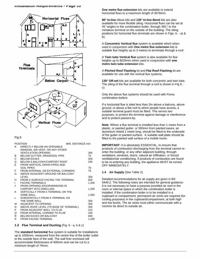
Fig 6
POSITION MIN. DISTANCE mmA DIRECTLY BELOW AN OPENABLE
WINDOW, AIR VENT, OR ANY OTHERVENTILATION OPENING 300
B BELOW GUTTER, DRAIN/SOIL PIPE 75C BELOW EAVES 200D BELOW A BALCONY/CARPORT ROOF 200E FROM VERTICAL DRAIN PIPES AND
SOIL PIPES 75F FROM INTERNAL OR EXTERNAL CORNERS 75G ABOVE ADJACENT GROUND OR BALCONY
LEVEL 300H FROM A SURFACE FACING THE TERMINAL 600I FACING TERMINALS 1,200J FROM OPENING (DOOR/WINDOW) IN
CARPORT INTO DWELLING 1,200K VERTICALLY FROM A TERMINAL ON THE
SAME WALL 1,500L HORIZONTALLY FROM A TERMINAL ON
THE SAME WALL 300M ADJACENT TO OPENING 300N ABOVE ROOF LEVEL (TO BASE OF TERMINAL) 300P FROM ADJACENT WALL TO FLUE 210Q FROM INTERNAL CORNER TO FLUE 230R BELOW EAVES OR BALCONY 600S FROM FACING TERMINAL 1,200
1.3 Flue Terminal and Ducting (Fig: 6 - a, b & c)
The standard horizontal flue system is suitable for installationsup to 1092mm, measured from the centre line of the boiler outletto the outside face of the wall. The wall liner enclosed willaccommodate thicknesses of 400mm and can be cut to aminimum length of 76mm.
One metre flue extension kits are available to extendhorizontal flues to a maximum length of 3078mm.
90° In-line elbow kits and 135° In-line Bend kits are alsoavailable for more flexible siting. Horizontal flues can be set at45 ° angles to the combination boiler, through 360 °, to theminiature terminal on the outside of the building. The sitingpositions for horizontal flue terminals are shown in Figs. 6. - a) &b).
A Concentric Vertical flue system is available which whenused in conjunction with One metre flue extension kits issuitable flue heights up to 3 metres to terminate through a roof.
A Twin tube Vertical flue system is also available for flueheights up to 8025mm when used in conjunction with onemetre twin tube extension kits.
A Pitched Roof Flashing kit and Flat Roof Flashing kit areavailable for use with the vertical flue systems.
135° Off-set kits are available for both concentric and twin tube.The siting of the flue terminal through a roof is shown in Fig 6. -c).
Only the above flue systems should be used with Pumacombination boilers.
If a horizontal flue is sited less than 2m above a balcony, aboveground, or above a flat roof to which people have access, asuitable terminal guard must be fitted. This serves twopurposes, to protect the terminal against damage or interferenceand to protect passers-by.
Note: Where a flue terminal is installed less than 1 metre from aplastic, or painted gutter, or 500mm from painted eaves, analuminium shield 1 metre long, should be fitted to the undersideof the gutter or painted surface. A suitable wall plate should befitted to the painted wall surface of a mobile home.
IMPORTANT: It is absolutely ESSENTIAL, to ensure thatproducts of combustion discharging from the terminal cannot re-enter the building, or any other adjacent building, throughventilators, windows, doors, natural air infiltration, or forcedventilation/air conditioning. If products of combustion are foundto be re-entering any building, the appliance MUST be turnedOFF IMMEDIATELY.
1.4 Air Supply (See Table 2)
Detailed recommendations for air supply are given in BS5440:2. The following notes are intended for general guidance:It is not necessary to have a purpose provided air vent in theroom or internal space in which the combination boiler isinstalled. If the combination boiler is to be installed in acupboard or compartment, permanent air vents are required (forcooling purposes) in the cupboard/compartment, at both highand low levels. The air vents must either communicate with aroom/or be direct to outside air.

Installation Requirements - Page 11
Table 2. Air Supply
1.5 Guide to System Requirements (Figs. 7 & 9)
These combination boilers are specifically designed forsealed systems only. Therefore the central heating systemshould be in accordance with the relevant recommendationsgiven in BS 6798 and also, smallbore and microboresystems BS 5449 Part 1.
For correct operation the boilers require a by-pass. Avalved by-pass should be fitted and the flow reduced tobalance the system correctly. The length of the by-passpipework is not important.
Note: If the by-pass flow is reduced too much this will causethe appliances to overheat and go to lockout.
The installation should be designed to work with flowtemperatures of up to 90°C. All components of the systemmust be suitable for a maximum pressure of 3 bar (45 psi)and a temperature of 110°C.
The following components are incorporated within theappliance.
a) Circulating pump*.b) Diverter valve.c) Pressure Relief valve with a non-adjustable pre-set lift
pressure of 3 bar (45 psi).d) Pressure gauge covering the range 0-4 bar (0-60 psi).e) 10 litre expansion vessel with initial charge pressure of
1.0 bar (14 psi).f) Domestic Hot Water flow switch.
* The pump supplied is sufficiently powerful forheating requirements upto 24kW providing thedesigned temperature drop across the heatingsystem is above 17°C (see pump performancecurve).
The central heating output from the boiler can easily bedownrated if a lower temperature drop across the system ispreferred.
If the central heating system requires an increased pumphead a second circulating pump should be installed. Thepump must be sited on the return to the boiler andelectrically connected using a propriety relay i.e. DraytonRB1 - see Section 2.6.
The domestic hot water system must be in accordance withthe relevant recommendations of BS 5546. Copper tubing toBS 2871:1 is recommended for water carrying pipework andMUST be used for pipework carrying potable water. Allcapillary joints in the D.H.W pipework must be joined with alead free solder.
Ancillary pipework, not forming part of the useful heatingsurface, should be lagged to prevent heat loss and anypossible freezing, particularly where pipes run through roofspaces and ventilated under-floor spaces.
If the capacity of the central heating system should exceed100 litres, an additional vessel should be installed on thereturn to the combination boiler from the heating system(Fig. 7). Guidance on vessel sizing is given in Table 3.
To allow the maximum central heating expansion capacity inthe boiler the pre-charge pressure in the central heatingexpansion vessel must be marginally greater than the initial(cold) system pressure at the appliance (as shown on theappliance pressure gauge).
Draining taps should be at least 1/2 in BSP nominal size andbe in accordance with BS 2879.
Table 3. Expansion Vessel RequirementsDeduct from the value given in the table the
10 litre expansion vessel supplied.

Installation Requirements - Page 12
To obtain economical use of the appliance it is advisable tofit external controls. The controls can take the form of:-
Time clock (two internal options are availablePart No. 31-19053 - Electro-mechanical)
b) Room thermostatThermostatic radiator valves (TRV's)Zone valves
A combination of these controls will produce economical and
advisable to control the temperature of the main living areawith a room thermostat and other areas by
Frost Protection
The appliance is fitted with an internal Frost Thermostat,
appliance. If any other part of the central heating systemrequires frost protection, an external frost thermostat must
1.6 Mains Water Feed: Central Heating
system to facilitate filling. There must be no directconnection to the return valve, without the approval of the Local WaterAuthority.
Note: The Puma combination boiler range is fitted with adesign which does not have a manual
operation lever to aid filling. Therefore to ease filling of the
diverter and must be opened during filling until water flowsout. The valve should then be closed. ( ).
(1) DIRECT METHOD
A detachable flexible hose is connected to a stop valve fittedto an outlet on the service main. The other end of the hose
valve. The double check valve is fitted to an inlet connectionon the central heating return pipe under the appliance. The
mainspressure is excessive a pressure reducing valve shall be
permanent part of the system and shall be fitted in the orderstated.
A stop valve complying with the requirements of BS1010Part 2, (the temporary hose from the draw off tap shall
b) Double check valve of an accepted type.
The system may be filled through a self contained unit
necessary, an automatic pressure-reducing valve or flowrestrictor.
the system to a minimum of 1.0 bar (14 p.s.i.) measured at
The cistern should be supplied through a temporaryconnection from a service pipe or cold water distributing
heating system to provide limited water make-up.
Provisions for make up water
system by re-pressurisation of the system. See section onMethods of Filling.
"Material and Installation Specifications for Domestic CentralHeating and Hot Water".
Installation to an Existing CentralHeating System
only, therefore if the existing system is of the open type it will
Before installing a new combination boiler to an existingsystem flush out the old system with a recommended
Also check pipework and renew any corroded pipework orfittings. Valve glands must be re-packed or replaced
1.8 Hard Water Areas
(above 200 p.p.m.) it is essential that a suitable water
be installed in the mains water supply.

Installation Requirements - Page 13
Fig 9
To assess water hardness, immerse a test strip for aboutone second in a water sample (NOT IN RUNNING WATER)so as to moisten all the zones.
Inspect the strip after 1-2 minutes, check the zones, if two ormore zones have changed colour the hardness of the wateris above 200 p.p.m. and a water treatment device will berequired.
1.9 Pump Performance Curve
The circulating pump fitted within the appliance should becapable of satisfying most system requirements. For centralheating systems greater than 15kW it may be necessary touse a higher "design temperature drop across system" tomeet the system pump head requirement. The designtemperature drop should not exceed 20°C (36°F). Fig. 9indicates the amount of pump head available for the system.The boiler resistance is already taken into account in thiscurve.
HOW TO USE FIG. 9.
Starting with the required SYSTEM HEATING LOAD, draw avertical line downwards so that it intersects the chosenSYSTEM DESIGN TEMPERATURE DROP line, normallythis would be 11°C (20°F) although up to 17°C (30°F) can beused without increasing radiator sizes. From this intersectionpoint draw a horizontal line so that it intersects the PUMPCURVE. From this intersection draw a vertical line upwards.
The AVAILABLE PUMP HEAD can now be read from thehorizontal scale, and the corresponding FLOW RATE from
the vertical scale in the centre of the chart.
The system must be designed so that its hydraulicresistance does not exceed the available head unless anadditional circulating pump is fitted.
If the designed flow rate through the boiler is less than 11.5l/min, the boiler could be noisy and ultimately overheat. Seenote on system by-pass in Section 1.5.
Central Heating Range Rate
For most installations the boiler will automatically adjust thecentral heating output to match your heating systemrequirement.
Systems which have very low water content and a lowheating requirement may benefit by reducing the maximumboiler output. This is achieved by rotation of the adjustmentknob, located on the electronic modulation control board.(Fig. 30).
The boiler central heating output can be adjusted betweenthe maximum and minimum values stated on the databadge. Operation of this adjuster will not affect the maximumboiler output when domestic hot water is being drawn off.

Installation Requirements - Page 14
1.10 Electrical Supply
Wiring external to the appliance MUST be in accordance with the current I.E.E. Regulations for Electrical Installations, andany Local Regulations which apply. The combination boiler is supplied for 230 Volts ~ 50 Hz, Single Phase. To protect theappliance it is essential that the electrical supply is fused at 3 A rating.
THIS APPLIANCE MUST BE EARTHED The method of connection to the mains electricity supply must provide means ofcompletely isolating the electrical supply to the combination boiler and its ancillary controls. The appliance is designed to bethe wiring centre for the installation, therefore no additional live supplies are required from either timers or room thermostats.
Isolation is preferably by the use of a fused three-pin plug and unswitched shuttered socket-outlet, both complying with therequirements of BS 1363. OR a 3 A fused double-pole switch, having a 3mm contact separation on both poles can be used.It is important that the point of connection to the mains should be readily accessible and adjacent to the combination boiler.

Installation Requirements - Page 15
1.11 Clearances around the Appliance.
Side Clearance:The position selected for the appliance must providethe following minimum clearance which is necessaryfor operation and servicing, 25mm each side (sideclearances have been incorporated into template).
Top Clearance:The top clearance should be a minimum of 160mm,but 300mm is preferred to allow removal of the centralheating expansion vessel, without removing theappliance from the wall, if replacement is required.
Bottom Clearance:A bottom clearance of 220mm is required between theappliance and any surface.
Frontal Clearance:A minimum of 500mm is required in front of theappliance for access during servicing, the frontclearance can be reduced providing the door/covercan be removed to expose the entire case front.

2. Boiler Installation - Page 16
It is MOST IMPORTANT that the appliance is installed in aVERTICAL POSITION, with the flue system passing throughthe wall or ceiling in a Horizontal or Vertical plane. A minordeviation from the horizontal is acceptable, provided that thisresults in a downward slope of the flue system away fromthe combination boiler.
2.1 Unpacking
The appliance will arrive on site in two separate cardboardcartons.
(1). The Large Carton. The Boiler - Containing:-
i) The Combination appliance c/w User Instructions(Note: Pipe tails and valves supplied on a vacuumformed card).
ii) These Installation and Service Instructions.iii) The wall fixing template.
(2). The Small Carton. The Flue System.
There is a range of horizontal and vertical flue systems andoptional packs (i.e. extensions / in-line bends etc.) to suityour requirements which are supplied separately from theboiler.
Installation instructions are included with each main pack.Make sure you have the flue you require.
a) Unpack the cartons and check the contents.
b) Remove the white front case as follows; undo the twosecuring screws at the base of the panel, pull the baseof the panel forward approx. 50mm and lift off thesupporting top hooks. (Fig. 15)
c) Remove the base cover by removing the two fixingscrews and push the cover towards the rear to release
d) Each side panel can now be individually removed byremoving the two front fixing screws, loosening the lowerrear fixing screw and sliding the panel upwards tounhook from the upper rear fixing. Place each panelsafely to one side.
e) Position the appliance onto its side and remove the fourscrews retaining the lowest rear cross brace. This braceis for transit purposes only and should be discarded.Remove all plastic plugs from the pipes.
f) At this point follow the Installation Instructions suppliedwith the Flue System, then proceed as follows:-
g) Boiler Connections.All connections to the appliance are suppliedunassembled in the boiler carton on a vacuum formedcard. Remove all fittings and assemble to the appliance.(Fig. 16).
Note: When fitted, the Red levered central heating tail(C.H.flow) should be to the left of the Blue.
2.2 Gas Connection(Fig. 16)
A minimum gas pressure of 20 mbar (8" w.g.) must beavailable at the combination boiler inlet at full flow rate, (seeTechnical Data).
Install a gas supply pipe not less than 15mm diametercopper to the combination boiler and connect to the gasservice cock.
Fig 15

Boiler Installation - Page 17
2.3 D.H.W. Supply
a) The domestic hot water circuit does not need a pressurerelief valve, but it is essential to ensure that the pressureof the cold water supply does not exceed 10 bar (145lb/in), if in doubt it is advisable to install a pressurereducing valve. The minimum pressure needed tooperate the domestic hot water system is 1 bar with aflow of approximately 2.5 litres per minute.
b) Flush out all foreign matter from the supply pipe beforeconnecting to the appliance.
c) Connect the cold water supply to the 15mm isolatingcock.Connect the hot water outlet pipe using a 15mmcompression fitting.
Note: 80 & 80e only, until hot water is available, the flowwill be restricted.
Note: The Cold Water Supply Isolating Cockincorporates an automatic flow limiting device and waterstrainer. If a lower flow is required there is a throttlevalve located below the D.H.W mini expansion vessel.
SHOWERS
If a shower control is to be supplied from the Combinationunit it should be of the type which incorporates a pressurebalancing valve (i.e. MIRA 415 EQUAMATIC).
If the shower control is existing and is of a mechanical type,it may be necessary to fit a drop tight pressure reducingvalve to the mains supply. Refer to the ShowerManufacturers instructions.
Note: Showers with a loose flexible hose may requirethe fitting of a double check valve, to comply with waterBye-law 17.
2.4 C.H. Water Connections(Fig. 16)
a) Before any central heating connections are made to thecombination boiler, all system valves should be openedand the system thoroughly flushed out with cold water.
b) Connect the central heating return pipe to the isolatingcock identified by a Blue lever. (right hand of the twopipes)
c) Connect the central heating flow pipe to the isolatingcock identified by a Red lever. (left hand of the twopipes)
Fig 16

Boiler Installation - Page 18
2.5 Pressure Relief Valve
The pressure relief valve is pre-set at 3 bar.
Install a pressure relief valve discharge pipe, not less than 15mm diameter and connect to the pressure relief outletconnection using a 15mm Compression fitting. The pipe runshould be as short as possible, run continuously downwardsand discharge to the outside of the building, where possibleover a drain. The pipe end should be directed towards the wall.(Fig. 17) The discharge point must be such that it will not behazardous to occupants or cause damage to external electricalcomponents or wiring.
IT MUST NOT DISCHARGE ABOVE AN ENTRANCE, ORWINDOW, OR ANY TYPE OF PUBLIC ACCESS. THEINSTALLER MUST CONSIDER THAT THE OVERFLOWCOULD DISCHARGE BOILING WATER.
Fig 17
2.6 Wiring the Appliance
The internal wiring of the appliance is shown in Figs. 42 & 46.The wiring diagram is also on the inside of the front casingpanel.
a) Undo the single retaining screw on the top of the controlspanel and allow the panel to swing down.
b) Using PVC insulated cable of not less than 0.75 mm².(24/0.2mm to BS 6500 Table 16), wire up the panelreferring to the termination label. (Fig. 18).
Note: Ensure that all cables pass through the wiring panelbush/s and are securely fixed by the cable clamp/s.
If a room thermostat is to be fitted, remove the Red link wirebetween terminals 3 and 4 and discard prior to wiring in thethermostat. If no room thermostat is to be fitted retain link wire.If a programmable room thermostat is to be used it must befitted in place of the external timer and the link between 3 & 4retained.If the installation does not have an internal or external timer thecentral heating switch on the front of the appliance must be setto Constant during periods when central heating is required.If using an internal timer connect the timers lead to PL11 on themodulation control board. (Fig. 30).If an external frost thermostat is required it should be connectedto terminals 3 and 8. For the frost thermostat to function theboiler switch must be set to ‘On’.
Secondary Pump. If a second pump is to be fitted to the centralheating system it should be sited on the return to the boiler andelectrically connected using a proprietary relay as shown in Fig.19.
c) Check all wiring and reposition the control panel.d) Secure with screw provided.
Note: The electrical mains supply must be fused at 3 A, and theconnection must be made to the wiring panel in such a way thatshould the lead disengage from the cable clamp, the currentcarrying conductors become taut before the earth conductor.
Read Section 2.6 for information onThermostats and Timers
Fig 18 Fig 19

3. Commissioning - Page 19
Fig 20
The Puma combination boiler has been through a rigoroustest procedure after manufacture and should not require anyfurther adjustment. If in the unlikely event of the appliancenot operating correctly please turn to the Control Flow,Functional Flow and Fault Finding charts that start onpage 42.
3.1 Electrical Installation
Conduct a preliminary electrical test by checking: for shortcircuits, fuse failure, incorrect polarity, earth continuity andresistance to earth. If a fault has occurred on the appliance,the fault finding procedure should be followed. See pages 39& 48.
3.2 Gas Installation
The whole of the gas installation including the meter, shouldbe inspected and tested for soundness and purged inaccordance with the recommendations of BS 6891. Purgingair from the gas line may be carried out by loosening theunion on the gas service cock and purging. Re-tighten theunion when completed and check for gas soundness.
N.B. Open all doors and windows, extinguish naked lightsand DO NOT SMOKE when carrying out the gas soundnesstests and purging.

Commissioning - Page 20
3.3 Initial Lighting(Fig. 20)
WARNING: Before operating the appliance, check that theair box covers are correctly fitted. The outer white front caseshould be left off for the time being. Carry out the followingprocedure in the order listed.
a) Thoroughly flush out the whole of the heating systemwith cold water.
b) Fill and vent the system until the pressure gaugeregisters 1.5 bar (21.5 psi), examine for leaks andrectify. Do not overtighten joints. During filling ensurethat the plastic screw on top of the automatic air vent isnot tight and air can escape. Do not tighten the airvent screw after filling. To ease filling an air bleedvalve (Fig. 16, Page 17) is fitted to the diverter valvewhich must be opened until water flows out. The valveshould then be closed.
c) Check the operation of the pressure relief valve byfurther raising the water pressure until the valve lifts.This should occur at approx. 3 bar, indicated on theappliance pressure gauge. If installing in a low pressurearea (below 3 bar) fill to the maximum pressurepossible.
d) Release water from the system using the pressure reliefvalve until the minimum system design pressure isreached. (Generally 1.0 bar). To allow maximum centralheating expansion capacity the pre-charge pressure inthe central heating expansion vessel must be marginallygreater than the initial (cold) system pressure at theappliance. If the position of the appliance in the systemwill cause the pressure at the appliance to be greaterthan 1 bar (14.5 lb/in) increase the pre-charge pressurein the central heating expansion vessel to a marginallygreater value prior to filling the system. Set the redpressure gauge indicator to coincide with this pressure.Check the pump spindle is free to rotate by unscrewingthe black octagonal nut, withdraw to engage the motorspindle. The knob should rotate freely. The pump willnormally self vent the air from the rotor chamber andbearings within a short while of switching on, howevershould manual venting be required, sideways pressureshould be applied and maintained to the knob until asmall amount of water becomes visible. The manualrestart knob should now be screwed back to its originalposition, finger tight.
e) Check that the boiler switch is set to Stand-by and thecentral heating switch is set to the Off position. (Midposition)
f) 80 & 80e. Check that the Hot Water and Central Heatingtemperature controls on the control panel are set to theirlowest setting.
g) Check the Gas service cock is On.
h) Check that the boiler isolating valves and radiator valvesare open.
i) Check that any time controls are in an On condition, andany room thermostats are calling for heat.
j) Switch On the main electricity supply to the combinationboiler at the wall isolating switch. The Mains light willnow illuminate.
k) Loosen or remove the outlet (burner) pressure test pointscrew in the gas valve body (Fig. 29), and connect via aflexible tube to the + or Hi side of pressure gauge. Thenconnect the - or Lo side of pressure gauge via anotherflexible tube to the pressure test point in the base of theinner casing. (Fig. 20)
On Permanent Pilot version only, light the pilot:
i. Press control knob in lightly and turn. Align Off position with marker .
ii. Press control knob in lightly and turn. Align ignitionposition with marker .
iii. Press control knob in firmly and hold, at the same timepress the ignition button. The pilot flame should bevisible at the pilot window. If not press the ignitionbutton until the flame is established.
iv. When the flame is established hold the control knob infor approximately 20 seconds before releasing. Thepilot flame should remain alight.
v. Press control knob in lightly and turn, align full flameposition with marker .
l) Switch the Boiler switch to On.
IMPORTANTCommission the boiler in Central Heating Mode
before Domestic Hot Water Mode
Adjusting the Central Heating Range Rate Pressure.See boxed Warning on page 21.
This pressure can only be measured in the central heatingmode.(i) Ensure all D.H.W outlets are turned off.(ii) Ensure all radiator control valves are fully open and any
room thermostats are calling for heat.(iii) 80 & 80e. Set central heating temperature control knob
to maximum.(iv) Set central heating switch to Constant. The burner will
now light but remain at low burner pressure forapproximately 2 minutes. After this time it will go tomaximum pressure. Allow the central heating to run for5 or 10 minutes.
(v) Using the range rate adjustment knob on the electroniccontrol board (Fig. 30) adjust to the values for RangeRate in Table 4 on page 22.
m) 80 & 80e. Turn the Hot Water temperature controlclockwise to its maximum setting.
n) Fully open a hot water tap. (After a short delay the mainburner will light (on electronic versions the flame lightwill illuminate.

Commissioning - Page 21
WARNING:
When the appliance is operating, wiring in the areaaround the gas valve and printed circuit boards will belive. When it is necessary in the following sections to
work in this area temporarily isolate the electricalsupply. However this can not be done when adjustingthe gas pressure therefore extra care must be taken
during this operation. Where it is necessary todisconnect a modulator coil wire (section 3.3 (q).)
disconnection should be made with the use ofelectrically insulated pliers and the connection should
be taped.
Adjustment of the Modulating Valve
Pressures are measured by connecting the +ve connectionto the gas outlet and -ve connection to the base of the innercasing as described in Section 3.3 (k).Set the pressures to the values in Table 4 by adjusting thegas valve in the following manner.
Note: It is important to note the order in which the maximumand minimum pressures are set.
The maximum pressure must always be set beforeadjustment of the minimum pressure.
WARNING: The pipes under the appliance could be hot,avoid contact with bare skin.
p) Fully open all domestic hot water outlets, vent flexiblehose connections to the washing machine anddishwasher. Remove air from the domestic hot waterdistribution system. If this is not done the internal waterflow switch will not function properly. Test for gassoundness around the gas components using leakdetector fluid.
q) Check the minimum burner pressure (see Table 4) bydisconnecting one of the Modulating Coil electricalconnections (wire colours Red or Black).
Note: The modulating coil connections are 24V only.Figs. 28 & 29.
r) Reconnect and check maximum burner pressure againstTable 4. If any adjustment is necessary see Section 3.4,Gas Pressure Adjustment.
Note: The boiler is so designed that if required the centralheating output can be down rated to the lowest setting statedon the data plate without affecting the D.H.W output. Ifadjustment is required see Section 3.4 Gas PressureAdjustment.
3.4 Gas Pressure Adjustment
Note: The gas pressures are set at the factory (with centralheating output set at maximum) and should not requirefurther adjustment. If gas pressure readings are beingobtained which differ from that stated in Table 4, check theinlet pressure using the inlet pressure test point on the gasvalve (Fig. 29). The inlet pressure should be checked withthe appliance at full gas rate, to ensure this occurs put a highwater flow through the domestic hot water side of thesystem.
Note: When checking gas inlet pressure only connect onetube from the measuring manometer's +ve side. Do notconnect the -ve tube as with minimum and maximumpressure readings.
Adjusting the Maximum Pressure (Fig. 21)See boxed Warning on this page.
(i) Cut off cable tie retaining modulator Cover.(ii) Remove Cover (C) by twisting it anticlockwise 90° and
levering off with a small screwdriver.(iii) With a 10mm spanner turn nut (B), (Clockwise to
increase pressure). Adjust to the value for maximumpressure stated in Table 4.
Adjusting the Minimum Pressure (Fig. 21)See boxed Warning on this page.
This adjustment is only to be made after the maximumsetting has been completed.
(i) Disconnect one of the electrical connections of themodulating coil and tape. (24V only)
(ii) Using a 10mm spanner hold nut (B) and adjust screw(A) with a screwdriver (clockwise rotation will increasethe pressure). Set to the value for minimum pressurestated in Table 4.
(iii) Reconnect the electrical connection to the modulator.(iv) Check maximum and minimum settings. Repeat
adjustment if required.(v) Refit cover (C), snap into place and turn.
After the setting operation remove the pressure gauge tubesfrom the gas valve body and inner casing. Refit the pressuretest point screws.

Commissioning - Page 22
Table 4. Gas Pressures
3.5 Products Of Combustion Measurement
The combustion performance can be assessed by placing asuitable sampling probe through the access hole in the innercasing door whilst the appliance is running. Typical figuresbased on a 500mm flue length with the boiler operating atmaximum output are:-
CO. 0.002 - 0.005%CO2. 4.5 - 5.0%
Replace the screw in access hole after test.

Commissioning - Page 23
3.6 D.H.W Flow Rate
The appliance contains an automatic flow regulator supplying anominal flow rate of 10 litres/minute (80 & 80e) and 7.6litres/minute (Saver). These flow rates will give a nominaltemperature rise of 35 °C & 45 °C respectively. Should it bedesired to set the appliance to give a higher temperature rise,the flow rate can be further reduced by using the manual flowrestrictor (clockwise to reduce) located in the manifold below themini expansion vessel - Fig. 22.
3.7 Central Heating
a) Ensure that all external controls such as a timers areswitched On and that room thermostat/s are calling forheat.
b) Set the Central Heating switch to Timed (if system fittedwith Timer) or Constant. The appliance will operate inaccordance with the pre-selected temperature set on thelower temperature control knob. (Fixed on Saver at 80 °C).
3.8 Temperature Controls - 80/80e
a) Central Heating
The lower control knob enables you to control thetemperature of the central heating flow as it leaves theappliance. This knob can be set between the - and +setting. The graduations correspond approximately to atemperature of 60 °C to 79 °C. Under a minimum load
condition the flow temperature can rise to 87 °C at maximumsetting. The appliance is fitted with a Central Heating switchwhich will allow you to switch Off the central heating during thesummer months (mid position).
b) Hot Water
The upper control knob enables you to control thetemperature of the domestic hot water as it leaves theappliance. The knob can be set between the - and +setting. The graduations - to + correspond approximately toa temperature of 45 °C to 65 °C.
3.9 Appliance Protection Devices
Loss of gas supply, flame failure, or over-heating of the centralheating water will cause the appliance to shut down or Lockout.
On the 80 model (with permanent pilot) this will be indicated bythe pilot being extinguished. To restart the appliance follow thelighting instructions on the boiler facia label or as shown inSection 3.3.
On the 80e/Saver models (electronic) this will be indicated bythe lockout light being illuminated. To Reset the appliance pressthe RESET button on the front panel and hold in that position for10 seconds and release. The appliance should now operatenormally.
If this is not the case refer to the Fault Finding guide either onthe rear of the white front case or pages 39 & 48 of theseinstructions.
80 & 80e. If the central heating system looses pressure for anyreason the appliance will cease to function and the Low SystemPressure light will illuminate. The system and the applianceshould be checked for leaks (including discharge from thepressure relief pipe). Correct any faults and re-pressurise thesystem with reference to Section 1.6. Mains Water Feed CentralHeating.
All models are fitted with a Frost thermostat which will bring theappliance On when the local temperature around the appliancefalls below 5 °C The appliance will shut down when thetemperature of the system water has been raised byapproximately 10 °C
The appliance is protected provided the Mains light isilluminated and the Boiler switch is set to On (and on permanentpilot models the pilot is alight), irrespective of the settings of anyexternal controls.
Note: the Frost thermostat will operate with the central heatingswitch in any position therefore when leaving the property incold weather for extended periods, the boiler will be protectedeven when the switch is set to Off (Mid position).
Note: While the appliance is being used to provide hot water atany draw off point, the central heating will not operate. Whenhot water is no longer required the appliance will automaticallyrevert to central heating.

Commissioning - Page 24
3.10 Refit the White Front Case.
3.11 Handing Over to the User
After completion of installation and commissioning of thesystem, the installer should hand over to the Householder bythe following actions:
a) Explain to the Householder where to find the User'sGuide and his/her responsibilities under the 'Gas Safety(Installation and Use) Regulations 1994. (As Amended)'.
b) Explain and demonstrate the lighting and shutting downprocedures.
c) Demonstrate the operation of the boiler including theuse and adjustment of all system controls. This thenensures the greatest possible fuel economy consistentwith household requirements of both heating and hotwater consumption. Advise the User of the precautionsnecessary to prevent damage to the system, and to thebuilding, in the event of the system remaininginoperative during frost conditions.
d) Explain the function and the use of the boiler switch,central heating switch and Reset button ('e' modelsonly).
e) Explain and demonstrate the function of time andtemperature controls, external frost thermostat (if fitted)and radiator valves, etc. for the economic use of thesystem.
f) If a Time Control is fitted (internal or external), then drawattention to the timer 'User Instructions' and hand themto the householder.
g) Stress the importance of regular servicing by a qualifiedHeating Engineer and that a comprehensive serviceshould be carried out AT LEAST ONCE A YEAR.
h) Explain the function of the Low System Pressureindicator light.
i) An internal frost thermostat is fitted to the appliance, itmust be explained that the Boiler switch must be in theOn position (with the mains light illuminated) to provideprotection of the appliance, if it is not to be used duringwinter periods.
Note: the Frost thermostat will operate with the centralheating switch in any position therefore when leaving theproperty in cold weather for extended periods, the boiler willbe protected even when the switch is set to Off (Midposition).

4. Servicing - Page 25
To ensure the continued safe and efficient operation of theappliance it is recommended that it is checked and servicedas necessary at regular intervals.
The frequency of servicing will depend upon the particularinstallation conditions and usage but in general, once peryear should be adequate. It is the law that all servicing workis carried out by competent person such as British Gas orother CORGI registered personnel.
WARNING: Before the start of any maintenance work,disconnect the mains electricity supply to the appliance byremoving the plug from the socket or by switching off at theexternal isolating switch. The gas distribution pipework andall associated appliances (including the boiler) must bechecked for gas soundness. The appliance gas supplyshould be isolated at the gas service cock, (one quarter turnof square spindle) if dismantling gas carrying components.
The following notes apply to the appliance but it should beremembered that attention must also be paid to the heatingand hot water systems in the property with special attentionto radiator valves, thermostats, clocks, leaking hot watertaps etc.
Where it is necessary to replace a gasket that relies onadhesive for securing - this adhesive will be supplied withthe gasket in the spares kit.
Prior to servicing, Remove the white front case (see 5.1 in`Routine Maintenance’). Operate the appliance by turningOn a hot water tap to a high water flow and observe themain burner.
Look through the sight glass and check that the flame coversall the flame ports and is of a light blue colour. Yellowflames and excessive lifting of flames indicate poorcombustion.
Inspect the pilot flame for size and colour. The pilot burnerpressure is non-adjustable. The pilot flame should heat thethermocouple so that the pilot safety device is "held in" butmust not cause the thermocouple to glow red. Figure 23illustrates the approximate size of the correct flame. If thereis excessive flame replace the pilot injector.
It is preferable to measure the CO% and CO2% content ofthe flue products. This is achieved by placing a suitablesampling probe into the fluehood via the sample test point onthe air box door.Typical figures based on a 500mm flue length with the boileroperating at maximum output are:-
CO 0.002 - 0.005%CO2 4.5 - 5.0 %
IMPORTANT: After completing any servicing or replacementof a gas carrying component, it is essential that a test for gassoundness is made and functional checks of controlsoperation carried out.

5. Routine Maintenance - Page 26
Routine Maintenance (Carry out the following sequence 5.1 -5.10)
5.1 Remove the White Front Case(Fig. 15 in the Boiler Installation Section).
a. Remove the two securing screws located at the base ofthe white front case assembly.
b. Ease the base of the case forward approximately 50mmand lift to release the panel from the securing hooks atthe top of the appliance.
c. Remove the case and place in a safe position away fromthe immediate working area.
5.2 Remove Base Panel
a. Remove the two securing screws retaining the basepanel to the case sides.
b. Lower the front edge and push backwards to releasecover
5.3 Remove the Air Box Covers
a. Take out the six securing screws and remove the mainair box cover.
b. Remove the two screws securing the front edge of eachwhite case side panels. This will allow the side panels tobe sprung outwards to improve access for the followingoperation.
c. Remove the four screws securing the two remaining airbox side covers and remove.
5.4 Remove the Fan Assembly
a. Disconnect the fan wiring by separating the in-lineconnector.
b. Support the fan and remove the two fixing screws fromthe front edge of the fan mounting plate. Lower the fanand carefully withdraw it from the appliance. Put in asafe place until required.
5.5 Remove the Flue Hood
a. Remove the two flexible tubes connected to the left andright hand sides of the fluehood.
b. Slacken the screw on the left-hand rear of the flue hood(but do not remove) and fully remove the remaining righthand screw.
c. Lift and remove the fluehood to expose the top surfaceof the heat exchanger.
5.6 Remove the Combustion ChamberFront Panel
a. Remove the two screws securing the combustionchamber front panel.
b. Remove the panel by pulling the top edge forwards andlifting the panel clear of the two lower retaining flanges.Ensure the insulation remains in position. The undersideof the heat exchanger is now exposed.
5.7 To Inspect and Clean the Boiler(Fig. 24)
a. Inspect the heat exchanger for any blockage. Depositsof any material should be brushed away using a softbrush.Note: Do not use brushes with metallic bristles.
b. Examine internal pipe work connections and automaticair vent for any water leaks. Rectify if necessary.
c. Examine the combustion chamber insulating materialand renew if damaged. To remove the combustionchamber side panels undo the single screw from eachside and pull panel forward. The insulation can now beremoved from the panel. To remove the insulation fromthe rear of the combustion chamber remove the twohexagonal burner location supports and take out the twoscrews from the insulation support bracket.Remove the support and slide the insulation downwardsfrom behind the heat exchanger.
Permanent pilot versions only.Inspect the pilot injector for any obstruction and clear orrenew as necessary.
d. Inspect the main burner and remove any deposits with asoft brush.
Electronic & Saver.Check the electrodes for damage or deterioration. Ensurethat the spark gaps are correct to dimensions specified inFig. 24. Clean or renew as necessary. Do not bend theelectrodes as the insulating material may crack.
e. Examine the fan for any mechanical damage (includingseals), check to ensure free running of the fan wheel.Clean the wheel if necessary with a soft brush.
Note: It is essential that a good seal is made at the fan,renew the sealing collar or fluehood sealing ring if thereare any signs of damage or deterioration. See section 6.17of Component Replacement.
f. Examine flue ducts and flue hood and ensure that thereis no obstruction. Re-assemble all components inreverse order, (ensure all seals are replaced correctly).See note above re-spare main burner seals.
Permanent pilot versions only.During re-assembly of the pilot injector, pilot tubethermocouple and spark electrode lead ensure allcomponents are clean and all joints are tight.
All TypesDuring re-assembly check the air box door and side coverseals for damage or deterioration and renew if necessary.

Routine Maintenance - Page 27I

Routine Maintenance - Page 28
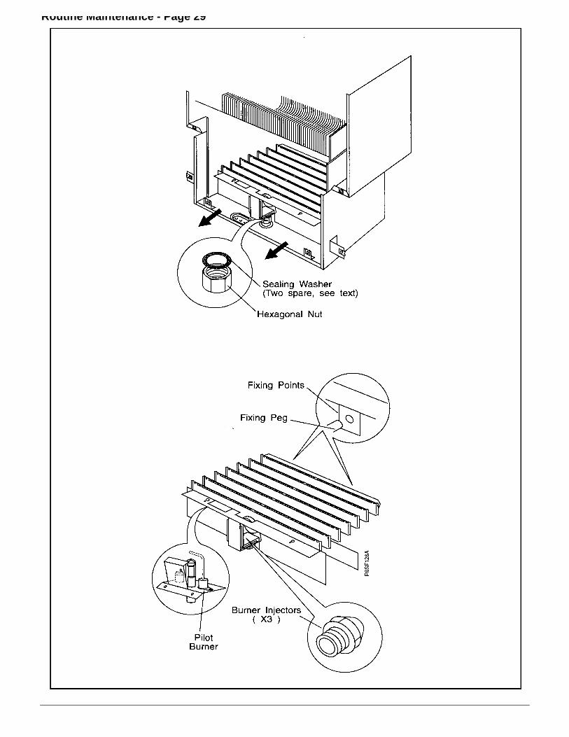
5.8 Remove the Burner(Fig. 25)
Electronic & Saver versionsa. Disconnect the two leads to the electrodes.
(Do not pull on the cable).
Permanent Pilot versionsa. Disconnect the pilot tube, thermocouple and spark
electrode lead and pull all three away from the pilotburner. Note: The pilot injector will be loose. Do notremove the two screws holding the pilot burner to themain burner.
All typesb. Undo the hexagonal union nut under the burner, taking
care not to loose the seal *. Carefully pull the burnerforward approximately 3 mm to disengage the rearburner supports, then lift the rear of the burner to anangle greater than 45°. Continue to roll the burner out ofthe appliance.
c. Remove the burner injectors separately to examine theirstatus, clean or renew as necessary.
* If, during removal of the burner the burner sealing washerbecomes damaged, the appliance is supplied as standardwith two spare sealing washers. They are in a polythene baglocated on the inside face of the base panel. Furtherwashers can be purchased from Potterton, Part No.13-18693. If the boiler has been operating, care must be takento avoid contact with any hot pipework on the underside ofthe appliance, during inspection and cleaning.
5.9 Gas Pressures - AdjustmentSee Section 3.4. Page 21.
5.10 The Central Heating Sealed System
Check that the pressure in the system is being maintained.The pressure gauge is fitted with a moveable red markerwhich indicates the initial filling pressure of the system whencold. If the pressure gauge needle indicates a lowerpressure than the red marker (or the Low System Pressurelight is illuminated - 80/80e only), the system has lostpressure and should be re-pressurised. The correctprocedures are shown in the installations section. See`permissible methods of filling’ Page 12.
5.11 Other Components
No further servicing is required on any other appliancecomponents. It is advisable to operate the three waterisolating taps to maintain free operation. It is recommendedthat the pressure relief valve is operated during servicing. Itmay occasionally be necessary to replenish the pre-chargein the expansion vessels. This can be readily achieved byuse of a portable air pump.
Note: The water side of either expansion vessel must bedepressurised prior to re-pressurising the air side.Access can be made to the charging points on therespective vessels, as follows:
a. Central Heating expansion vessel - access is made tothe vessel charging point from above on the right handside of the appliance. Re-pressurise to a minimum of 1bar (14.5 lb/in) or marginally greater than the designedsystem pressure at the appliance when cold, which everis higher.
b. Domestic Hot Water expansion vessel - access is madeby lowering the controls panel and removing the accesscover on the rear panel, also temporarily remove thetransformer - See 6.31. The vessel charge point cannow be connected. Re-pressurise the vessel to 3.5 bar(51 p.s.i) or higher if mains water pressure is higher.
Note: If the portable pump can not easily be connected, thevessel can be removed and re-pressurised off the appliance.(see section 6.25, Expansion vessel D.H.W.).
Routine Maintenance - Page 29

6. Component Replacement - Page 30
WARNING: Before attempting to remove any component from this appliance, first disconnect the mains electricity supply byremoving the plug from the wall socket or by switching off the appliance at the external isolating switch. Note: The appliancestand-by switch must not be used as the means of isolating, as this switch does leave parts of the appliance electrically live.
IMPORTANT: After removal or replacement of any gas carrying components a test for gas soundness must be made.
Notes: The appliance gas supply should be isolated at the boiler gas service cock (one quarter turn of square spindle).
The Central Heating and Domestic Hot Water circuits can similarly be isolated at their respective valves. A drainpoint is provided in the appliance heating circuit under the pump manifold and the cold water inlet isolating valvealso incorporates a drain screw. Use a suitable tube when draining to direct water away from the appliance.
When removing any water carrying components suitably protect the control box from accidental spillage.
Before removing any component from the central heating circuit on the appliance, reduce the pressure by closingthe isolating valves and opening the pressure relief valve.

Component Replacement - Page 31
6.1 Central Heating Overheat ThermostatFig. 27
a. Remove the white front case and three air box covers.See 5.1 & 5.3 in ‘Routine Maintenance’.
b. The thermostat is located on the outlet tail on the righthand side of the heat exchanger. Disconnect the twoelectrical leads.
c. Undo the two long fixing nuts and remove the thermostatfrom the heat exchanger.
d. Fit the new overheat thermostat taking care not to touchthe exposed disc on the thermostat face. Do Not useheat sink compound. Re-assemble in reverse order.
Fig 276.2 Domestic Hot Water Limit & Frost
Thermostats
a. Remove the white front case and base panel.See 5.1 to 5.3 in ‘Routine Maintenance’.Lower the control panel, (one screw).
b. Disconnect the electrical leads from the thermostat.c. Remove the two securing screws and pull the
thermostat clear of the pipe.d. Fit the new thermostat and re-assemble in reverse
order.
6.3 Sensor and Ignition Electrode
(Electronic & Saver versions only)a. Remove the white front case, base panel, air box covers
and combustion chamber front panel. See 5.1 & 5.3 &5.6 in ‘Routine Maintenance’.
b. Disconnect the lead from the base of the electrode to bechanged.Remove the electrode retaining screw and remove theelectrode from the burner.
c. Fit new electrode and re-assemble in reverse order,checking the gap measures 4mm ± 0.5mm (Fig. 24).
6.4 Sensor and Ignition Leads
(Electronic & Saver versions only)a. Remove the white front case, base panel and main air
box cover. See 5.1 to 5.3 in ‘Routine Maintenance’.b. Lower control panel (one screw)c. Note run of lead.
Remove lead ends from electrode and Full SequenceControl Board. Pass lead through the silicone grommet.
d. Fit new lead in correct position.e. Re-assemble in reverse order. Ensure the silicone
grommet is correctly fitted and not damaged. Replace ifnecessary.
6.5 Spark Ignition Lead
(Permanent Pilot versions only)a. Remove the white front case, base panel and main air
box cover. See 5.1 to 5.3 in ‘Routine Maintenance’.b. Lower control panel (one screw)c. Note run of lead.
Remove lead ends from electrode and ignitor button.Pass lead through the silicone grommet.
d. Fit new lead in correct position.e. Re-assemble in reverse order. Ensure the silicone
grommet is correctly fitted and not damaged. Replace ifnecessary.
6.6 Thermocouple
(Permanent Pilot versions only)a. Remove the white front case, base panel and main air
box cover. See 5.1 to 5.3 in ‘Routine Maintenance’.b. Lower control panel (one screw)c. Loosen the nuts at both ends of the thermocouple and
partly withdraw each connection.d. Cut through the defective thermocouple where it passes
through the silicone grommet and remove both halvesfrom the boiler.
e. Fit a new thermocouple retaining nut to the pilot.f. Carefully feed the new thermocouple through the
silicone grommet and push fully into the retaining nutuntil it hits its stop. Tighten thermocouple nut.
g. Position thermocouple along route, avoid sharp bendswhich may kink copper sleeve. Connect to gas valve.
h. Re-assemble in reverse order. Ensure the siliconegrommet is correctly fitted and not damaged. Replace ifnecessary.

Component Replacement - Page 32
6.7 Burner(Fig. 25)
a. Remove the white front case, air box covers,combustion chamber, front panel and burner assembly.See 5.1, 5.3, 5.6 & 5.8 in ‘Routine Maintenance’.
b. Remove the electrodes or pilot burner from the mainburner and re-assemble onto the new main burner. (Onelectronic only, check electrode gap is 4mm ± 0.5 Fig.24).
c. Re-assemble in reverse order.
6.8 Injectors(Fig. 25)
a. Remove the white front case, air box covers,combustion chamber front panel and burner assembly.See 5.1, 5.3, 5.6 & 5.8 in ‘Routine Maintenance’.
b. With the main burner removed, release the burnermanifold by removing the 4 screws to give access to theinjectors.
c. Replace the relevant injector/s ensuring that the brasswasher is fitted under each injector.
d. Re-assemble in reverse order.
6.9 Gas Valve(Fig. 28)
a. Remove the white front case, base panel & white lefthand side panel.See 5.1, 5.2 & 5.3 in ’Routine Maintenance’.
b. Isolate the gas supply at the gas cock (1/4 turn).c. On either valve remove the electrical connectors from
the modulating valve, the plug from the first solenoidvalve (Electronic & Saver only) and gas valvecompensation tube. On the permanent pilot versionremove the connections on the interrupter, spark igniterand thermocouple. Disconnect the pilot tube.
d. Undo the nut on the lower gas supply tube.e. Support the gas valve assembly and undo the nut on the
burner supply pipe under the air box. Remove the gasvalve assembly from the appliance.
f. Remove the second solenoid valve (2 screws).g. Remove the screw and disconnect the electrical
connector to the second solenoid valve and remove therubber gasket.
h. Before the new gas control valve is fitted, fit the rubbergasket to the second solenoid valve and secure theelectrical connector to the second solenoid valve (1screw), transfer the burner feed pipe and lower gassupply tube to the new valve. Replace the 'O' rings ifnecessary. On Permanent pilot versions refit theinterrupter and the valve knob extension.
i. Re-assemble in reverse order ensuring that the blackand red wires (low voltage) are connected to themodulator valve (Fig. 28 or 29) Polarity is not important.
6.10 Modulating Valve
a. Remove the white front case.See 5.1 in ’Routine Maintenance’.
b. Disconnect the electrical connections to the modulatingvalve. (Red and Black).
c. Remove the clear plastic cover by cutting off the nylontie, twisting the cover anti-clockwise 90° and levering offwith a small screwdriver.
d. Using a 14mm spanner unscrew the complete innercartridge and remove with niting plate.
e. Lift off the solenoid coil and remove from metal bracket,f. Replace in reverse order ensuring the notch in the niting
plate is located over the raised pip on the new solenoidcoil.
g. Reconnect the red and black wires to the terminationson the modulation coil. Polarity is not important.
h. Reset the gas pressure - see 3.4 'Commissioning', Page21.
i. Refit the clear plastic cover, snap into place and turn.
6.11 First Solenoid Valve Coil(Fig. 29)
(Electronic versions only)
a. Remove the white front case.See 5.1 in 'Routine Maintenance'.
b. Disconnect the electrical connecter to the first solenoidvalve.
c. Remove the first solenoid valve (2 screws).d. Replace the solenoid valve in reverse order.e. Re-commission the appliance as described in section 3.
6.12 Second Solenoid Valve
(All versions)
a. Remove the white front case.See 5.1 in 'Routine Maintenance'.
b. Remove the second solenoid valve (2 screws).c. Remove the screw and disconnect the electrical
connecter to the second solenoid valve.d. Transfer the rubber gasket to the new solenoid valve.e. Replace the solenoid valve in reverse order.f. Re-commission the appliance as described in section 3.
6.13 Case Seals
a. Remove the white front case, base cover and air boxcovers.See 5.1, 5.2 & 5.3 in ’Routine Maintenance’.
b. Peel off the existing case seal(s).c. Fit new seal(s) and re-assemble, in reverse order.

Component Replacement - Page 33

Component Replacement - Page 34

Component Replacement - Page 35
Fig 30
6.14 Central Heating and Boiler Switches
a. Remove the white front case and base panel.See 5.1 & 5.2 in ‘Routine Maintenance’.Lower the facia panel, (1 screw).
b. Make note of the wire routing and switch orientation anddisconnect the molex plug from the electronic controlboard.
c. Using a small screwdriver press the retaining lugs on theswitch body sides inwards and remove the switch fromthe control panel. Withdraw the switch and leads andfeed the molex plug through the cut out in the panel
d. Fit new switch assembly and re-assemble in reverseorder. Ensure that the switch is the correct way round inthe panel i.e. when the Stand-by/On switch is On, thered indicator line on the switch can be seen.
e. Re-fit the molex plug to the correct plug position on theelectronic control board.
6.15 Electronic & Saver Control Boards(Fig. 30)
The electronic control assembly is in three parts:i. The User Display Board.ii. The Control Board.iii. The Full Sequence Control Board, (not fitted to
permanent pilot version).a. Remove the white front case and base panel.
See 5.1 & 5.2 in ‘Routine Maintenance’.
(i) USER DISPLAY BOARDa. Remove the thermostat knobs (80 & 80e only) and
reset button.b. Undo the fixing screw retaining the facia panel and
swing the panel downwards.c. Remove the plug connector/s from the rear of the board
and undo the four securing screws.d. Replace board and re-assemble in reverse order.
(ii) MODULATION CONTROL BOARDNote: The board has a replaceable fuse rated at 2A.
a. Undo the fixing screw retaining the facia panel andswing the panel downwards.
b. Remove the plug connectors on the larger control boardand undo the four securing screws.
c. Replace the board and re-assemble in reverse order.
(iii) FULL SEQUENCE CONTROL BOARD(not on permanent pilot versions)
a. Undo the fixing screw retaining the control panelassembly (top right hand side of control box) and swingthe control assembly downwards.
b. Remove the cover over the full sequence control (twoscrews).
c. Slide the electrode and flame sensors wire connectionsout of their respective slots on the board. Disconnect allplug connections and carefully remove the earth tab.
d. At each of the four standoff pillars, push the small barbinwards and lift the board free.
e. Replace the board and re-assemble in reverse order.
Component Replacement - Page 35
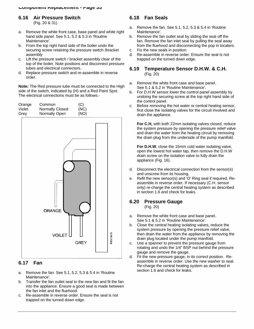
6.16 Air Pressure Switch(Fig. 20 & 31)
a. Remove the white front case, base panel and white righthand side panel. See 5.1, 5.2 & 5.3 in 'RoutineMaintenance'.
b. From the top right hand side of the boiler undo thesecuring screw retaining the pressure switch /bracketassembly
c. Lift the pressure switch / bracket assembly clear of thetop of the boiler. Note positions and disconnect pressuretubes and electrical connectors.
d. Replace pressure switch and re-assemble in reverseorder.
Note: The Red pressure tube must be connected to the Highside of the switch, indicated by (H) and a Red Paint Spot.The electrical connections must be as follows.-
Orange Common (C)Violet Normally Closed (NC)Grey Normally Open (NO)
6.17 Fan
a. Remove the fan. See 5.1, 5.2, 5.3 & 5.4 in ‘RoutineMaintenance’.
b. Transfer the fan outlet seal to the new fan and fit the faninto the appliance. Ensure a good seal is made betweenthe fan inlet and the fluehood.
c. Re-assemble in reverse order. Ensure the seal is nottrapped on the turned down edge.
6.18 Fan Seals
a. Remove the fan. See 5.1, 5.2, 5.3 & 5.4 in ‘RoutineMaintenance’.
b. Remove the fan outlet seal by sliding the seal off thefan. Remove the fan inlet seal by pulling the seal awayfrom the fluehood and disconnecting the pop in locaters.
c. Fix the new seals in position.d. Re-assemble in reverse order. Ensure the seal is not
trapped on the turned down edge.
6.19 Temperature Sensor D.H.W. & C.H.(Fig. 20)
a. Remove the white front case and base panel.See 5.1 & 5.2 in ’Routine Maintenance’.
b. For D.H.W sensor lower the control panel assembly byundoing the securing screw at the top right hand side ofthe control panel.
c. Before removing the hot water or central heating sensor,first close the isolating valves for the circuit involved anddrain the appliance.
For C.H, with both 22mm isolating valves closed, reducethe system pressure by opening the pressure relief valveand drain the water from the heating circuit by removingthe drain plug from the underside of the pump manifold.
For D.H.W, close the 15mm cold water isolating valve,open the lowest hot water tap, then remove the D.H.Wdrain screw on the isolation valve to fully drain theappliance (Fig. 16).
d. Disconnect the electrical connection from the sensor(s)and unscrew from its housing.
e. Refit the new sensor(s) and 'O' Ring seal if required. Re-assemble in reverse order. If necessary (C.H. sensoronly) re-charge the central heating system as describedin section 1.6 and check for leaks.
6.20 Pressure Gauge(Fig. 20)
a. Remove the white front case and base panel.See 5.1 & 5.2 in ’Routine Maintenance’.
b. Close the central heating isolating valves, reduce thesystem pressure by opening the pressure relief valve,then drain the water from the appliance by removing thedrain plug located under the pump manifold.
c. Use a spanner to prevent the pressure gauge fromrotating and undo the 1/4" BSP nut behind the pressuregauge and remove the gauge.
d. Fit the new pressure gauge, in its correct position. Re-assemble in reverse order. Use the new washer to seal.Re-charge the central heating system as described insection 1.6 and check for leaks.
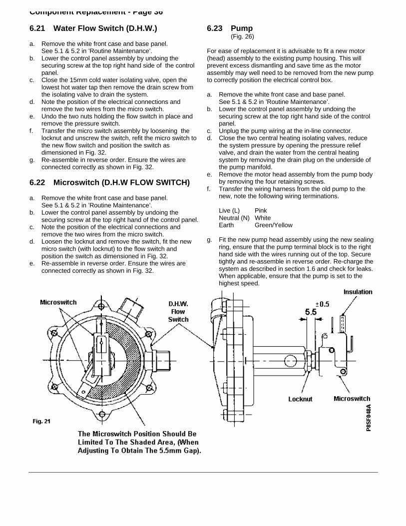
Component Replacement - Page 36
6.21 Water Flow Switch (D.H.W.)
a. Remove the white front case and base panel.See 5.1 & 5.2 in ’Routine Maintenance’.
b. Lower the control panel assembly by undoing thesecuring screw at the top right hand side of the controlpanel.
c. Close the 15mm cold water isolating valve, open thelowest hot water tap then remove the drain screw fromthe isolating valve to drain the system.
d. Note the position of the electrical connections andremove the two wires from the micro switch.
e. Undo the two nuts holding the flow switch in place andremove the pressure switch.
f. Transfer the micro switch assembly by loosening thelocknut and unscrew the switch, refit the micro switch tothe new flow switch and position the switch asdimensioned in Fig. 32.
g. Re-assemble in reverse order. Ensure the wires areconnected correctly as shown in Fig. 32.
6.22 Microswitch (D.H.W FLOW SWITCH)
a. Remove the white front case and base panel.See 5.1 & 5.2 in ’Routine Maintenance’.
b. Lower the control panel assembly by undoing thesecuring screw at the top right hand of the control panel.
c. Note the position of the electrical connections andremove the two wires from the micro switch.
d. Loosen the locknut and remove the switch, fit the newmicro switch (with locknut) to the flow switch andposition the switch as dimensioned in Fig. 32.
e. Re-assemble in reverse order. Ensure the wires areconnected correctly as shown in Fig. 32.
6.23 Pump(Fig. 26)
For ease of replacement it is advisable to fit a new motor(head) assembly to the existing pump housing. This willprevent excess dismantling and save time as the motorassembly may well need to be removed from the new pumpto correctly position the electrical control box.
a. Remove the white front case and base panel.See 5.1 & 5.2 in ’Routine Maintenance’.
b. Lower the control panel assembly by undoing thesecuring screw at the top right hand side of the controlpanel.
c. Unplug the pump wiring at the in-line connector.d. Close the two central heating isolating valves, reduce
the system pressure by opening the pressure reliefvalve, and drain the water from the central heatingsystem by removing the drain plug on the underside ofthe pump manifold.
e. Remove the motor head assembly from the pump bodyby removing the four retaining screws.
f. Transfer the wiring harness from the old pump to thenew, note the following wiring terminations.
Live (L) PinkNeutral (N) WhiteEarth Green/Yellow
g. Fit the new pump head assembly using the new sealingring, ensure that the pump terminal block is to the righthand side with the wires running out of the top. Securetightly and re-assemble in reverse order. Re-charge thesystem as described in section 1.6 and check for leaks.When applicable, ensure that the pump is set to thehighest speed.

Component Replacement - Page 37
Fig 33
Fig 34
6.24 Diverter Valve(Fig. 33)
The diverter valve is made up in two parts. The wax capsulehead forms one part and provides the motive power to openthe valve. The second part, the valve consists of the changeover mechanism and the valve seating. It is likely that onlyreplacement of the head will be necessary, if the completevalve requires replacement proceed to (ii).
(i) Wax Capsule Head
a. Remove the white front case and base panel.See 5.1 & 5.2 in ’Routine Maintenance’.
b. Lower the control panel assembly by undoing thesecuring screw at the top right hand side of the controlpanel.
c. Close the 15mm cold water isolating valve, open thelowest hot water tap and remove the D.H.W drain screwin the isolating valve to drain the system.
d. Close the central heating isolating valves, reduce thesystem pressure by opening the pressure relief valveand drain the water from the heating system byremoving the drain plug from the underside of the pumpmanifold.
e. Undo the two D.H.W pipe connections to the valvehead. Retain the two pipe seals.
f. Unscrew the two grub screws (2mm hexagon key)which hold the head to the main body. Pull the headforwards using a twisting action and carefully removethe head. Note the position of the loose brass cylinderon the wax capsule push rod and transfer onto newhead assembly.
g. Fit new wax capsule head, re-assemble in reverseorder. Replace pipe seals is necessary.
(ii) Complete valve replacement
a. Remove the white front case and base panel.See 5.1 & 5.2 in ’Routine Maintenance’.
b. Lower the control panel assembly by undoing thesecuring screw at the top right hand side of the controlpanel.
c. Close the 15mm cold water isolating valve, open thelowest hot water tap and remove the D.H.W drain screwon the isolating valve to drain the system.
d. Close the central heating isolating valves, reduce thesystem pressure by opening the pressure relief valveand drain the water from the heating system byremoving the drain plug from the underside of the pumpmanifold.
e. Undo the two D.H.W pipe connections from the head ofthe diverter valve. Retain the pipe seals.
f. Undo the Central heating pipe connections to thediverter valve body and loosen the two nuts retainingthe C.H. Flow and Return pipe tails.
g. Remove the locknut at the rear of the diverter valveholding the valve to the front cross brace.
h. Undo connection to the pump manifold and withdrawthe diverter valve from the boiler. Transfer the waterpressure switch and drain cock to the new valve and re-assemble in reverse order.

Component Replacement - Page 38
6.25 Expansion Vessel D.H.W.(Fig. 34)
Isolate the electrical supply prior to this operation.
a. Remove the white front case and base panel.See 5.1 & 5.2 in ’Routine Maintenance’.
b. Lower the control panel assembly by undoing thesecuring screw at the top right hand side of the controlpanel. Close the isolating valve on the cold water inletand open the lowest hot water tap. Remove the drainscrew on the isolating valve to completely drain theappliance. Replace drain screw in isolator valve.
c. Remove the access panel to the left of the transformer.Temporarily remove the transformer - See 6.31.
Note: It is not necessary to fully remove the top right handscrew.
d. Release the vessel by unscrewing it from the inletmanifold.
e. Carefully withdraw the vessel through the access hole.Refit new component.
f. Re-assemble in reverse order, using a new sealingwasher. Open the isolating valve, and check for leaks.
6.26 Expansion Vessel C.H.
In the unlikely event of a failure of the C.H. expansion vesselit is recommended that a new vessel be fitted exterior to theboiler. It should be positioned on the C.H. Return pipe (seeFig. 7) as close to the boiler as possible. If however, thevessel must be replaced then the following procedures mayby used. Installations with vertical flue systems must be fittedwith exterior expansion vessels if the flue system can noteasily be raised a minimum of 50mm.
Note: It will simplify fitment of the vessel if a length of stringor flexible wire is attached to the end of the flexible pipe andpassed down the rear of the appliance through the backpanel hole and used as a guide to thread the pipe duringinstallation.
PROCEDURE 1. Horizontal flues only.
If the clearance above the boiler is greater than 300mmproceed as follows:
a. Remove the white front case.See 5.1 in ‘Routine Maintenance’.
b. Lower the control panel assembly by undoing thesecuring screw at the top right hand side of the controlpanel.
c. Close the central heating flow and return isolatingvalves, release the system pressure by operating thepressure relief valve drain the appliance by removing thedrain plug on the underside of the pump manifold.
d. Undo the flexible pipe connection on the side of thepump manifold and remove the grommet. Push theflexible pipe through the hole in the back panel.
e. For rear outlet flues remove the flue elbow (4 screws)
f. Remove the top expansion vessel securing bracketassembly (four screws) and slide the vessel (completewith flexible pipe) upwards out of the appliance.
g. Remove the flexible pipe from the old vessel and refit(using a new sealing washer) to the new expansionvessel (at this stage the pre-charge pressure can beeasily checked and corrected if necessary. The pressureshould be at least equal to the system pressure at theappliance).
h. Fit the new expansion vessel and re-assemble inreverse order. Ensure that the vessel is located correctlyin the lower support bracket. Route the flexible pipethrough the hole in the back panel and refit grommet.
PROCEDURE 2
If the clearance above the appliance is less than 300mmthe appliance must be removed from the wall.
a. Remove the complete casing assembly (front, base andsides)
b. Close all the isolating valves, reduce the pressures inthe appliance by operating the pressure relief valve andopening the lowest hot water tap. Drain the remainingwater in the boiler by removing the drain screw underthe pump manifold (C.H.) and on the 15mm isolatingvalve (D.H.W).
c. Lower the control panel assembly by undoing thesecuring screw at the top right hand side of the controlpanel.
d. Disconnect the input wiring noting positions of wires andthread wiring out of control panel grommet/s.
e. Check the gas supply is isolated at the gas service cock,(1/4 turn of square head), undo the gas cock union nutand position nut clear of thread.
f. Undo the upper isolator valve connections on the C.H.flow, return and Cold water inlet valves. Similarlydisconnect hot flow pipe, and pressure relief pipes.
g. Disconnect the flue elbow from the top of the appliance,(4 screws), lift the flue elbow off the boiler connectionand rotate the elbow 180° to position the flue clear of theappliance. If a vertical flue system is fitted it will requireraising approximately 50mm (2") to allow the boiler to belifted off its hanging screws.
h. Remove the bottom boiler securing screw then loosenthe appliance upper securing screws and lift the boileroff the wall. Place unit face downwards on the floor.Care should be taken not to damage the pressure gaugeor electronics.
j. Access can now be made to the expansion vessel. Undothe flexible pipe connection to the vessel and removethe screws retaining the upper expansion vessel bracketto release the vessel from the appliance.
k. Fit a new expansion vessel and re-assemble in reverseorder, using a new sealing washer. At this stage it isadvisable to check the pre-charge.

Component Replacement - Page 396.26 Heat Exchanger (Fig. 24).
a. Perform 5.1 to 5.6 & 5.8 in ‘Routine Maintenance’. Removethe combustion chamber insulation by removing each sidepanel retaining screw and pulling the complete side panel/insulation assembly forwards. The rear insulation canremain in situ.
b. Close all the isolating valves, reduce the pressures in theappliance by operating the pressure relief valve andopening the lowest hot water tap. Drain the remaining waterin the boiler by removing the drain screws under the pumpmanifold (C.H.) and on the 15mm isolating valve (D.H.W).Undo the heat exchanger connection to the auto air ventpipe.
c. Disconnect the electrical connections from the C.H.overheat thermostat. The control box should be protectedfrom water spillage.
d. Release the four spring clips retaining the heat exchangertails by pulling the clip forwards and towards the centre ofthe appliance and ease the heat exchanger up, out of thehousings.
e. The heat exchanger waterways can now be descaled or areplacement heat exchanger can be fitted, in which casethe overheat thermostat must be transferred to the newheat exchanger.
f. Re-assemble in reverse order. Use a soap solution tolubricate the new ‘O’ rings when fitting the new heatexchanger, also, ensure the heat exchanger is pushed fullydown. Re-charge the system as described in section 1.6and check the joints for leaks.
6.28 Automatic Air Vent (Fig. 35)
a. Remove the white front case, base panel and white lefthand side panel. See 5.1, 5.2 & 5.3 in 'RoutineMaintenance'.
b. Close the central heating isolating valves, reduce thesystem pressure by opening the pressure relief valve, thenpart drain the water from the boiler by opening the bleedvalve on the right hand side of the diverter valve.
c. Using a spanner to prevent the retaining nut from rotatingunscrew the auto air vent and remove from the appliance. Ifthere is insufficient space, removal will be eased if thecomplete auto air vent and pipe assembly is disconnectedfrom the heat exchanger and then raised above the top ofthe air box. To do this the fan and fluehood will need to beremoved, see 5.4 & 5.5 in ‘Routine Maintenance’
d. Fit new air vent and sealing washer ensuring the air ventcap is left loose.Re-assemble in reverse order, ensure that the grommet iscorrectly positioned. Re-charge the system as described insection 1.6 and check for leaks.
6.29 Pressure Relief Valve (Fig. 36)
a. Remove the white front case and base panel.See 5.1 & 5.2 in ’Routine Maintenance’.
b. Close the central heating isolating valves, reduce thesystem pressure by opening the pressure relief valve, thendrain the water from the appliance by removing the drain offscrew on the underside of the pump manifold.
c. Undo the outlet tube nut and fully remove the two grubscrews holding the pressure relief valve to the pumpmanifold, undo the top compression joint on the pressurerelief valve discharge pipe then remove the valve.

Component Replacement - Page 40
Note: The outlet of the pressure relief valve is an oliveconnection.
d. Fit the new pressure relief valve using a new ‘O’ ringseal and soap solution as a lubricant. Re-assemble inreverse order.
e. Recharge the system as described in section 1.6 andcheck for leaks.
6.30 Water Pressure Switch - 80/80e Only(Fig. 37)
a. Remove the white front case and base panel.See 5.1 & 5.2 in 'Routine Maintenance'.
b. Close the central heating isolating valves, reduce thesystem pressure by opening the pressure relief valve,then drain the water from the appliance by removing thedrain off screw on the underside of the pump manifold.
c. Lower the control panel assembly by undoing thesecuring screw at the top right hand side of this controlpanel.
d. Remove the two wire connections and unscrew theswitch from the diverter valve.
e. Fit the new switch using a new sealing washer.f. Re-assemble in reverse order. Electrical polarity is not
important. If there are three terminals, do not use theterminal insulated by sleeving.The wires must be connected to the terminals on theswitch body marked 1 & 2. (Normally Closed)
g. Open the isolating valves. Re-charge the system asdescribed in section 1.6 and check for leaks.
6.31 Transformer Assembly(Fig. 38)
a. Remove the white front case and base panel.See 5.1 & 5.2 in ’Routine Maintenance’.
b. Lower the control panel assembly by undoing thesecuring screw at the top right hand side of the controlpanel.
c. Remove the transformer wiring loom from the retainingcable ties and unplug the connector to the electroniccontrol board PL 6 (top right hand side of control board).Thread the wiring out of the control panel.
d. Remove the two screws retaining the transformer to theback panel and remove transformer from appliance.
e. Fit the new transformer assembly in reverse order.
6.32 Sight Glass With Securing Frame
a. Remove the white front case, base panel and air boxmain cover. See 5.1, 5.2 & 5.3 in ‘Routine Maintenance’.
b. On the inside of the inner door straighten the fourretaining tags. Remove sight glass.
c. Renew the sight glass and use a new gasket to seal.d. Re-assemble in reverse order.

7.1 Control Flow Sequence - Permanent Pilot - Page 41

7.2 Functional Flow - Permanent Pilot - Page 42

7.3 Fault Finding - Permanent Pilot - Page 43
Before attempting any electrical fault finding, carry out a preliminary electrical test by checking: for short circuits, fuse failure, incorrect polarity, earthcontinuity and resistance to earth. For replacement of fault component, (see Section - Component Replacement). To assist in fault-finding, thelogic sequence of the electronics control circuit precedes the fault-finding charts.
Preliminary Actions: A) Set Boiler Switch to Stand-by.C) Set H.W. & C.H. Temp. Controls to MAX.E) Ensure all isolating valves at the base of the applianceare OPEN.G) Arrange for system controls to be calling for heat.
B) Set Heating Switch to ‘OFF’ (centre).D) Turn OFF all Hot Water Taps.F) Turn ON EXTERNAL GAS & ELECTRICAL supplies.
Fig.41

7.4 Electrical Diagram - Permanent Pilot - Page 44
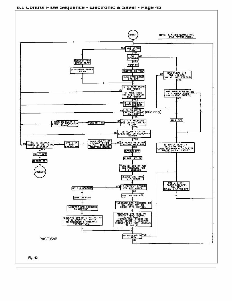
8.1 Control Flow Sequence - Electronic & Saver - Page 45
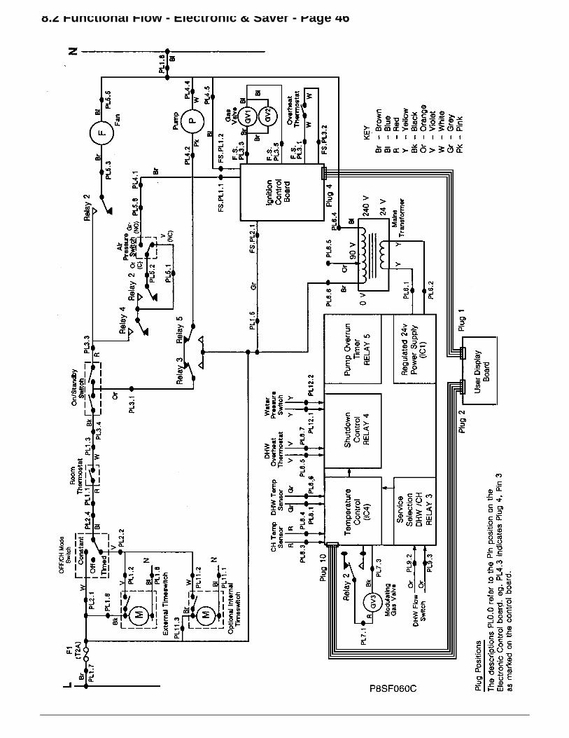
8.2 Functional Flow - Electronic & Saver - Page 46

8.3 Fault Finding - Electronic & Saver - Page 47
Before attempting any electrical fault finding, carry out a preliminary electrical test by checking: for short circuits, fuse failure,incorrect polarity, earth continuity and resistance to earth. For replacement of fault component, (see Section - ComponentReplacement). To assist in fault-finding, the logic sequence of the electronics control circuit precedes the fault-finding charts.
Preliminary Actions: A) Set Boiler Switch to Stand-by. B) Set Heating Switch to 'OFF' (centre). C) Set H.W. & CHTemp. Controls to MAX. D) Turn OFF all Hot Water Taps. E) Ensure all isolating valves at the base of the appliance areOPEN.F) Turn ON EXTERNAL GAS & ELECTRICAL supplies. G) Arrange for system controls to be calling for heat

8.4 Electrical Diagram - Electronic & Saver - Page 48

9. Short List of Spares - Page 49

Short List of Spares - Page 50
Item Description Qty PottertonPart No.
Gas CouncilPart No.
1 Modulation Control Board - 80 1 929685 289 5502 Modulation Control Board - 80e 1 929686 289 5512 Modulation Control Board - Saver 1 21/207603 Display Board - 80 1 929687 289 5524 Display Board - 80e 1 929688 289 5534 Display Board - Saver 1 21/207615 Full Sequence Control Board - 80e/Saver 1 929689 289 5556 Pump Kit (Myson Compact) 1 929636 289 7307 Pilot Burner Assembly Kit - 80 1 10/201758 Thermocouple c/w Locknut - 80 1 10/203709 Main Burner Assembly 1 10/2016210 Transformer c/w Wiring 1 929681 289 54711 Spark Electrode - 80 1 22/2018212 Electrode Kit - 80e/Saver 2 929550 289 47813 Pressure Relief Valve - 3 bar c/w 'O' Ring 1 929647 379 39814 Gas Valve - SIT - 80 1 929578 379 46715 Gas Valve - SIT - 80e/Saver 1 402988 379 34916 Pressure Gauge 1 929644 289 53117 Burner Injector, Polidoro 1.15mm 3 22/2020718 Air Flow Switch - Honeywell C6065A1093 1 642212 379 35019 Diverter Valve Assembly Complete 1 929651 289 71820 Wax Capsule Assembly 1 929803 289 74121 D.H.W. Flow Switch 1 929673 289 72422 D.H.W. Thermostat/Flow Limiter Assembly - 80/80e 1 929670 289 73722 D.H.W. Housing Assembly - Saver 1 10/1971723 Fan Assembly 1 929501 379 34224 Piezo Igniter Assembly 1 929583 289 71725 Electrode Lead Assembly - 80 1 929544 289 47526 Electrode Lead Assembly - 80e/Saver 1 929551 289 47927 Detection Lead Assembly - 80e/Saver 1 929552 289 48028 D.H.W/C.H. Temperature Sensors 2 430011 289 52829 'O' Rings 2 929632 285 57230 Water Pressure Switch 1 642215 379 61531 C.H. Limit Thermostat (36TE21-12785) - 80e/Saver 1 929562 379 34832 D.H.W. Overheat Thermostat (36TE21-12786) 1 929634 379 39733 Frost Protection Thermostat (36TE21-12784) 1 929635 379 39634 Overheat Thermostat c/w Leads - 80 1 929839 289 735

back page