Installation Reference Guide - Enviro
6
65” (1651mm) 20” (508mm) 38” (965mm) 55” (1397mm) STEEL STUD 1” (25mm) Clearance from framing studs to venting C44 FIREPLACE Installation Reference Guide REFER TO OWNER’S MANUAL FOR SPECIFIC INSTALLATION REQUIREMENTS AND ADDITIONAL PRODUCT INSTRUCTIONS Clearance to Combustibles A - Finishing edge to side wall 7" 229 mm B - Minimum clearance to enclosure ceiling 65" 1651 mm C - Minimum clearance to mantel height See Chart See Chart D - Front of door to edge of floor protection 0" 0 mm E - Minimum alcove width 60" 1524 mm D B C E A Depth 20” 508 mm Width 55” 1397 mm Header Height 38” 965 mm Enclosure Ceiling 65” 1651 mm Minimum Framing Dimensions Note: Vent size 5/8
Transcript of Installation Reference Guide - Enviro

65”(1651mm)
20”(508mm)
38”(965mm)
55”(1397mm)
S T E E L S T U D
1” (25mm) Clearance from framing studs to venting
C44 FIREPLACE
Installation Reference Guide
REFER TO OWNER’S MANUAL FOR SPECIFIC INSTALLATION REQUIREMENTS AND ADDITIONAL PRODUCT INSTRUCTIONS
Clearance to Combustibles
A - Finishing edge to side wall 7" 229 mm
B - Minimum clearance to enclosure ceiling 65" 1651 mm
C - Minimum clearance to mantel height See Chart See Chart
D - Front of door to edge of floor protection 0" 0 mm
E - Minimum alcove width 60" 1524 mm
D
B
C
E
A
Depth 20” 508 mm
Width 55” 1397 mm
Header Height 38” 965 mm
Enclosure Ceiling 65” 1651 mm
Minimum Framing Dimensions
Note: Vent size 5/8

Non-Combustible Board Placement
Mantel ProjectionsMantel graph dimensions are measured from the bottom of the fireplace, if you wish to reference the mantel height from the tiling edge subtract 15 inches (381mm) from the mantel height depicted on the graph. If you plan to install a TV above your fireplace refer to the appropriate section of the owner’s manual for available options. It is acceptable to install a combustible mantel over top of the non-combustible board. If you are acti-vating the Cool Surface System you are eligible to subtract 12” (305mm) from the mantel height shown in this diagram.
Minimum Venting RequirementsMinimum venting is shown in figure 28. the framing height to the center of the thimble is 50”. Minmum venting must include a 12” vertical section and a 90 degree elbow which is then terminated horizontally. For a vertical termination please follow the vent pipe manufacturer’s installation instructions for vertical vent termination framing. A minimum of 1 in. (25 mm) clear-ance on all sides of the vertical vent pipe must be maintained. For every 12” of horizontal run there must be a 1/4” of rise. 1” of clearance between framing and venting must be maintained at all times. 2” above the venting and 3” above an elbow.
Fireplace Dimensions
1 2 3 4 5 6 7 8 9 10 11 12 13 14
MA
NT
LE
HE
IGH
T
M A N T L E D E P T H
Minimum Mantle Clearances
8” MANTLE
4”MANTLE
47
46
45
44”
43”
42”
41”
39”
40”
12” MANTLE
56 1/2”
13 3/4”
10”
COMBUSTIBLE
NON COMBUSTIBLE
Framing
MetalStud
Drywall
ConcreteBoard
Sidewall
7”
5 3/16
6
SpecificationsDimensions:
Rating LabeL & Lighting instRuctions Location:
Remove the screen completely to access the rating label and lighting instructions. The plates are attached to a length of chain and are never to be tampered with or removed. All important information for your fireplace is on this label as well of the model specific serial number which you will need for warranty information. The plates are located inside the cabinet on the left side near the front.
Figure 1. C44 Dimensions
46 14 "
1174mm
16 14 "
413mm
12"305mm
7 516 "
186mm
30 1116 "
779mm
9 34 "
247mm
49"1245mm
Gas Inlet Right Side
9 18 "
232mm
4 116 "
103mm
3 14 "
83mm
9 18 "
232mm
38"965mm
Electrical InletLeft Side
9 18 "
231mm
17 1316 "
453mm
54 78 "
1394mm
19 1516 "
507mm
12 "
13mm
11 316 "
284mm
2 1116 "
68mm
7"178mm
Gas InletBottom (Optional)
20"509mm
50"1272mm

OPTIONAL STEP Cool Surface System Part 1
Dimensions
7 58 "
(19.4 cm)
45" (114.3 cm)
31 34 " (80.6 cm)
25" (63.5 cm)
5" Vent Collars
40" (101.6 cm)
9 38 "
(23.8 cm) 2 3
4 " (7 cm) Standoff
2 12 " (6.6 cm) Standoff 11 7
8 "(30.2 cm)
7 38 "
(18.7 cm)
2 18 "
(5.4 cm)
12 "
(1.3 cm)
3 12 " (8.9 cm)
2 58 " (6.7 cm)
CSS Front Vent - Overall Dimensions (C34/C44/C60)
CSS Side Vent - Dimensions
76 78 "
1952mm
51 12 "
1308mm
7 58 "
192mm
53"1346mm
5" Vent Collars
2 18 "
53mm
12 "
13mm
3 1
2 "
89mm
2 58 "
67mm
7 14 "
185mm
9 38 "
237mm
11 78 "
301mm
71 78 "
1825mm
2 34 "
70mm
2 12 "
64mm
76 78 "
1952mm
51 12 "
1308mm
7 58 "
192mm
53"1346mm
5" Vent Collars
2 18 "
53mm
12 "
13mm
3 1
2 "
89mm
2 58 "
67mm
7 14 "
185mm
9 38 "
237mm
11 78 "
301mm
71 78 "
1825mm
2 34 "
70mm
2 12 "
64mm
76 78 "
1952mm
51 12 "
1308mm
7 58 "
192mm
53"1346mm
5" Vent Collars
2 18 "
53mm
12 "
13mm
3 1
2 "
89mm
2 58 "
67mm
7 14 "
185mm
9 38 "
237mm
11 78 "
301mm
71 78 "
1825mm
2 34 "
70mm
2 12 "
64mm
Figure 4. Cool Surface System Front Vent - Overall Dimensions (C72)
8.00
6.1
7
8.4
2
14.39
0.8
8
2.6
3
7.47
11.74
6.0
7 4
.65
10.
72 7.6
7
0.50
12.18
14.92
1.39
12.
24
13.64
36.00
4.75
4.75
4.75
9.95
26.00
36.00
9.75 2.48
.49
.49
2.48
4.75
.50
2.00
.92
.50
.50
36.00
4.75
4.75
4.75
9.95
26.00
36.00
9.75 2.48
.49
.49
2.48
4.75
.50
2.00
.92
.50
.50
36.00
4.75
4.75
4.75
9.95
26.00
36.00
9.75 2.48
.49
.49
2.48
4.75
.50
2.00
.92
.50
.50
36.00
4.75
4.75
4.75
9.95
26.00
36.00
9.75 2.48
.49
.49
2.48
4.75
.50
2.00
.92
.50
.50
36.00
4.75
4.75
4.75
9.95
26.00
36.00
9.75 2.48
.49
.49
2.48
4.75
.50
2.00
.92
.50
.50
36.00
4.75
4.75
4.75
9.95
26.00
36.00
9.75 2.48
.49
.49
2.48
4.75
.50
2.00
.92
.50
.50
36.00
4.75
4.75
4.75
9.95
26.00
36.00
9.75 2.48
.49
.49
2.48
4.75
.50
2.00
.92
.50
.50
Figure 5. Cool Surface System Combustible Facing Kit Dimensions
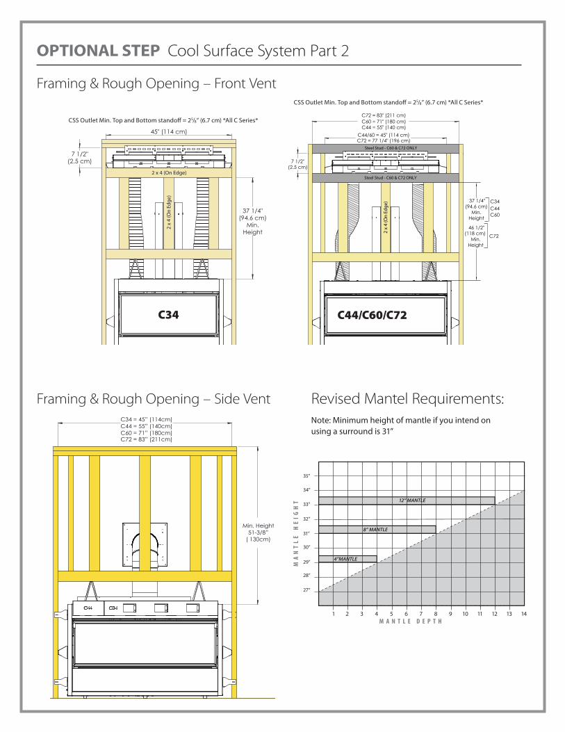
OPTIONAL STEP Cool Surface System Part 2
Framing & Rough Opening – Side Vent
Framing & Rough Opening – Front Vent
CSS Outlet Min. Top and Bottom standoff = 25/8” (6.7 cm) *All C Series*
7 1/2"(2.5 cm)
45" (114 cm)
37 1/4"(94.6 cm)
Min.Height
2 x 4 (On Edge)2
x 4
(On
Edge
)
C34
7 1/2"(2.5 cm)
C44/60 = 45" (114 cm)
2 x
4 (O
n Ed
ge) 37 1/4"
(94.6 cm) Min.
Height
C60 = 71" (180 cm)C44 = 55" (140 cm)
Steel Stud - C60 & C72 ONLY
Steel Stud - C60 & C72 ONLY
C72 = 83" (211 cm)
46 1/2" (118 cm)
Min. Height
C72
C34
C60 C44
C72 = 77 1/4" (196 cm)
C44/C60/C72
CSS Outlet Min. Top and Bottom standoff = 25/8” (6.7 cm) *All C Series*
Min. Height51-3/8”
( 130cm)
C34 = 45” (114cm)C44 = 55” (140cm)C60 = 71” (180cm)C72 = 83” (211cm)
Revised Mantel Requirements: Note: Minimum height of mantle if you intend on using a surround is 31”
1 2 3 4 5 6 7 8 9 10 11 12 13 14
MA
NT
LE
HE
IGH
T
M A N T L E D E P T H
Minimum Mantle Clearances
8” MANTLE
4”MANTLE
35”
34”
33”
32”
31”
30”
29”
27”
28”
12” MANTLE

OPTIONAL STEP Cool Surface System Part 3
Venting Clearances - Front Vent
Shown here are the minimum framing and clearances for the CSS when the fireplace is installed with the minimum allowable vent length:
Min. Ceiling Clearance from top of CSS outlet = 4” (10.2 cm)Min. Ceiling Clearance in wall from top of CSS Body = 55/8” (14.3 cm)CSS Body Min. Rear standoff = 2¾” (69.8 cm)
5 58 " (14.3 cm) 4" (10.2 cm)
2 34 " (69.8 cm)
73 14 "
(174.9 cm)Side BraceMin. Height
20" (50.8 cm)Min. Depth
39” (99 cm) Min. Length 5” dia. flex vent
(not supplied)
80” (203 cm) C34/44/60 Min. Ceiling
Min. Vent
82 3/8” (212 cm) Side Brace Min. Height
91” (231 cm)C72 Min. Ceiling
C34C44C60
C72
Venting Clearances – Side Vent
CSS Horizontal Vent - Min. Framing & Clearances CSS Vertical Vent - Min. Framing & Clearances
15.00” (38cm)
11.50”(29cm)
Min. Heightto Ceiling
14.50
Min. Height 66.00”
(168cm)
Min. toCeiling5” (12.5cm)
Min. Height from �oor69.5” (176.5cm)
39” (99 cm) Min. Length 5” dia. flex vent
(not supplied)
Min. Vent
Min. Distance towall from standoff 5.00” (13cm)
Min. CeilingHeight 18.75”
(48cm)
*15
.75”
(40
cm)
11.5” (29cm)
Min. Dist 61.75”
(157cm)
*NOTE: 15.75” from the header is required for min. ceiling height. Rest unit on
lower standoff. There will be a 3/4“ (2cm) gap on from
the top standoff to the header in this confirguration.
Min Framing is 15” x 11.5”
3/4” (2cm) Gap Shown
Min. Distanceto Ceiling4.5” (11.5cm)
Min. Distanceto �oor64” (162.5cm)
39” (99 cm) Min. Length 5” dia.
flex vent(not supplied)

OPTIONAL STEP Cool Surface System Part 4
TV Installation Considerations:If you are planning to mount a TV above your fireplace some considerations must be made to ensure it is protected from the heat.
During testing temperatures did not exceed 121°F (49°C) midway up the front wall (Figure 12 & 13). There is no guarantee that these temperatures will not harm the longevity of your TV. Make sure to consult your TV manufacturer’s specifications to find the maximum allowable operating temperature. Since every home and installation is unique, temperatures should be verified at the time of install if possible. If desired, front wall temperatures can be lowered to 104°F (40°C) with the use of a mantle (Figure 13). Refer to page 7 for revised mantle clearances. A TV should not be installed if temperatures exceed the manufacturers maximum allowable temperature.
Figure 12. CSS - TV Clearances Figure 13. CSS - TV Clearances
29°F 41”
21°F 35”
21°F 29”
24°F 23”
17°F 17”
20°F 11”
30°F 5”
0”
Abo
ve
Am
bien
t
Hei
ght f
rom
Ope
ning
4” Mantle29” from �oor.
Combustible Facing Kit
1/2” Combustible Base Material (Drywall)
Up to 1” Combustible Material.
NOTE: You cannot install a Surroundwith the mantle at its lowest position.
Install mantle at 31” for a Surround
Min. 2-1/2” (6.4cm)
Min. 2” (5cm)Gap
Combustible Facing Kit
1/2” Combustible Base Material (Drywall)
Up to 1” Combustible Material
29°F 41”
29°F 35”
29°F 29”
27°F 23”
35°F 17”
38°F 11”
49°F 5”
0”
Abov
e Am
bien
t
Hei
ght f
rom
Ope
ning
1-1/2” Air Gap behind the TV. (Typically provided by a wall mount)
TV must be 5” min from
discharge if no mantle
Framing Clearances - Front Vent Framing Clearances - Side Vent
Min. 3/4” (1.9cm) Mantel Thickness
29 “(74cm)
31 “(79cm)
Min. Height For Surround
33“(84cm)
4” (102mm)
8” (203mm)
12” (305mm)
2-1/16”(75cm)
Min. Heightto Ceiling55-1/16” (1399cm)
Min. Height to Ceiling64 1/8”
(1630mm)
C34C44C60
C72
29 “(74cm)
31 “(79cm)
Min. Height For Surround
33“(84cm)
4” (102mm)
8” (203mm)
12” (305mm)
2-1/16”(75cm)
Min. Heightto Ceiling55-1/16” (1399cm)