
INSTALLATION - parts.jacobsvehiclesystems.com · 6 JACOBS ENGINE BRAKE™ 340 SERIES INSTALLATION...
12
™ INSTALLATION Jacobs Engine Brake ® 340 Series
Transcript of INSTALLATION - parts.jacobsvehiclesystems.com · 6 JACOBS ENGINE BRAKE™ 340 SERIES INSTALLATION...
™
INST
ALLATIO
N
Jacobs Engine Brake®
340 Series
2 JACOBS ENGINE BRAKE™ 340 SERIES INSTALLATION MANUAL
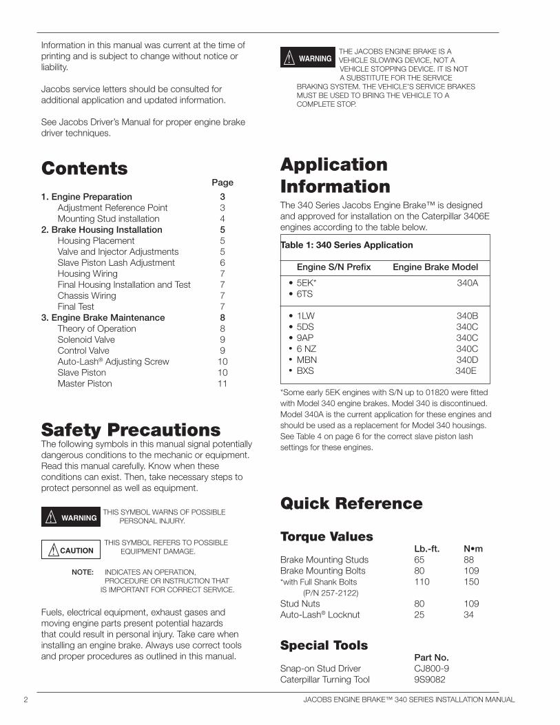
Quick Reference
Torque Values Lb.-ft. N•mBrake Mounting Studs 65 88Brake Mounting Bolts 80 109 *with Full Shank Bolts 110 150 (P/N 257-2122) Stud Nuts 80 109Auto-Lash® Locknut 25 34
Special Tools Part No.Snap-on Stud Driver CJ800-9Caterpillar Turning Tool 9S9082
Information in this manual was current at the time of printing and is subject to change without notice or liability.
Jacobs service letters should be consulted for additional application and updated information.
See Jacobs Driver’s Manual for proper engine brake driver techniques.
Contents Page
1. Engine Preparation 3 Adjustment Reference Point 3 Mounting Stud installation 42. Brake Housing Installation 5 Housing Placement 5 Valve and Injector Adjustments 5 Slave Piston Lash Adjustment 6 Housing Wiring 7 Final Housing Installation and Test 7 Chassis Wiring 7 Final Test 73. Engine Brake Maintenance 8 Theory of Operation 8 Solenoid Valve 9 Control Valve 9 Auto-Lash® Adjusting Screw 10 Slave Piston 10 Master Piston 11
Safety PrecautionsThe following symbols in this manual signal potentially dangerous conditions to the mechanic or equipment. Read this manual carefully. Know when these conditions can exist. Then, take necessary steps to protect personnel as well as equipment.
THIS SYMBOL WARNS OF POSSIBLE PERSONAL INJURY.
Fuels, electrical equipment, exhaust gases and moving engine parts present potential hazards that could result in personal injury. Take care when installing an engine brake. Always use correct tools and proper procedures as outlined in this manual.
THE JACOBS ENGINE BRAKE IS A VEHICLE SLOWING DEVICE, NOT A VEHICLE STOPPING DEVICE. IT IS NOT A SUBSTITUTE FOR THE SERVICE
BRAKING SYSTEM. THE VEHICLE’S SERVICE BRAKES MUST BE USED TO BRING THE VEHICLE TO A COMPLETE STOP.
THIS SYMBOL REFERS TO POSSIBLE EQUIPMENT DAMAGE.
Application Information
*Some early 5EK engines with S/N up to 01820 were fitted with Model 340 engine brakes. Model 340 is discontinued. Model 340A is the current application for these engines and should be used as a replacement for Model 340 housings. See Table 4 on page 6 for the correct slave piston lash settings for these engines.
Table 1: 340 Series Application
Engine S/N Prefix Engine Brake Model
• 5EK* 340A• 6TS
• 1LW 340B• 5DS 340C• 9AP 340C• 6 NZ 340C• MBN 340D• BXS 340E
The 340 Series Jacobs Engine Brake™ is designed and approved for installation on the Caterpillar 3406E engines according to the table below.
NOTE: INDICATES AN OPERATION, PROCEDURE OR INSTRUCTION THAT IS IMPORTANT FOR CORRECT SERVICE.
JACOBS ENGINE BRAKE™ 340 SERIES INSTALLATION MANUAL 3
Section 1: Engine Preparation
Adjustment Reference Point
No. 1 piston at Top Dead Center (TDC) on the compression stroke is the starting point for all timing procedures, and is the reference point for all engine valve and engine brake adjustments. Perform the following procedure to rotate the engine to this position.
1. Remove the three valve covers.
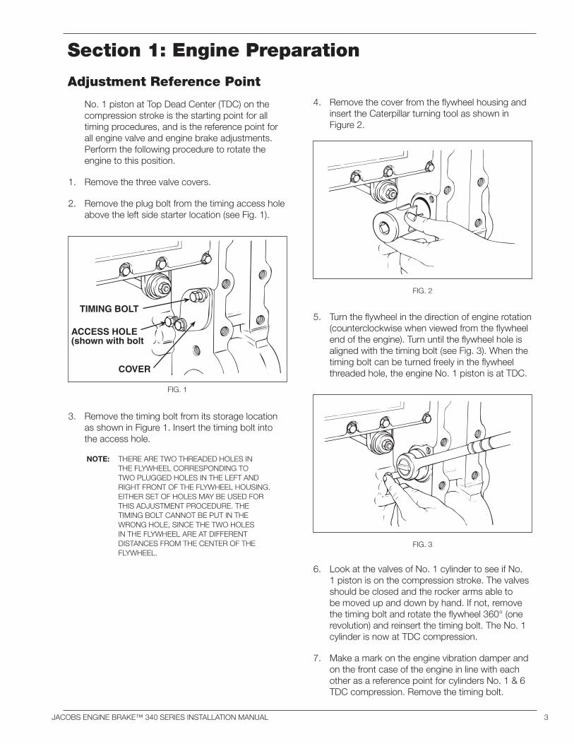
2. Remove the plug bolt from the timing access hole above the left side starter location (see Fig. 1).
4. Remove the cover from the flywheel housing and insert the Caterpillar turning tool as shown in Figure 2.
6. Look at the valves of No. 1 cylinder to see if No. 1 piston is on the compression stroke. The valves should be closed and the rocker arms able to be moved up and down by hand. If not, remove the timing bolt and rotate the flywheel 360° (one revolution) and reinsert the timing bolt. The No. 1 cylinder is now at TDC compression.
7. Make a mark on the engine vibration damper and on the front case of the engine in line with each other as a reference point for cylinders No. 1 & 6 TDC compression. Remove the timing bolt.
3. Remove the timing bolt from its storage location as shown in Figure 1. Insert the timing bolt into the access hole.
NOTE: THERE ARE TWO THREADED HOLES IN THE FLYWHEEL CORRESPONDING TO TWO PLUGGED HOLES IN THE LEFT AND RIGHT FRONT OF THE FLYWHEEL HOUSING. EITHER SET OF HOLES MAY BE USED FOR THIS ADJUSTMENT PROCEDURE. THE TIMING BOLT CANNOT BE PUT IN THE WRONG HOLE, SINCE THE TWO HOLES IN THE FLYWHEEL ARE AT DIFFERENT DISTANCES FROM THE CENTER OF THE FLYWHEEL.
FIG. 3
FIG. 2
FIG. 1
TIMING BOLT
ACCESS HOLE(shown with bolt
COVER
5. Turn the flywheel in the direction of engine rotation (counterclockwise when viewed from the flywheel end of the engine). Turn until the flywheel hole is aligned with the timing bolt (see Fig. 3). When the timing bolt can be turned freely in the flywheel threaded hole, the engine No. 1 piston is at TDC.
4 JACOBS ENGINE BRAKE™ 340 SERIES INSTALLATION MANUAL
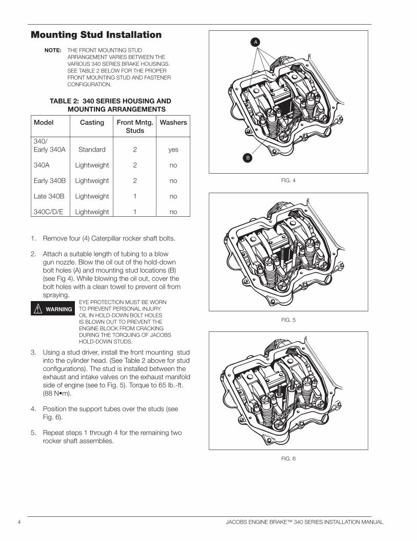
1. Remove four (4) Caterpillar rocker shaft bolts.
2. Attach a suitable length of tubing to a blow gun nozzle. Blow the oil out of the hold-down bolt holes (A) and mounting stud locations (B) (see Fig 4). While blowing the oil out, cover the bolt holes with a clean towel to prevent oil from spraying.
3. Using a stud driver, install the front mounting stud into the cylinder head. (See Table 2 above for stud configurations). The stud is installed between the exhaust and intake valves on the exhaust manifold side of engine (see to Fig. 5). Torque to 65 lb.-ft. (88 N•m).
4. Position the support tubes over the studs (see Fig. 6).
5. Repeat steps 1 through 4 for the remaining two rocker shaft assemblies.
Mounting Stud Installation
NOTE: THE FRONT MOUNTING STUD ARRANGEMENT VARIES BETWEEN THE VARIOUS 340 SERIES BRAKE HOUSINGS. SEE TABLE 2 BELOW FOR THE PROPER FRONT MOUNTING STUD AND FASTENER CONFIGURATION.
FIG. 5
FIG. 6
FIG. 4
A
B
TABLE 2: 340 SERIES HOUSING AND MOUNTING ARRANGEMENTS
Model Casting Front Mntg. Washers Studs
340/Early 340A Standard 2 yes
340A Lightweight 2 no
Early 340B Lightweight 2 no
Late 340B Lightweight 1 no
340C/D/E Lightweight 1 no
EYE PROTECTION MUST BE WORN TO PREVENT PERSONAL INJURY. OIL IN HOLD-DOWN BOLT HOLES IS BLOWN OUT TO PREVENT THE ENGINE BLOCK FROM CRACKING DURING THE TORQUING OF JACOBS HOLD-DOWN STUDS.
JACOBS ENGINE BRAKE™ 340 SERIES INSTALLATION MANUAL 5
Section 2: Brake Housing Installation
Housing Placement
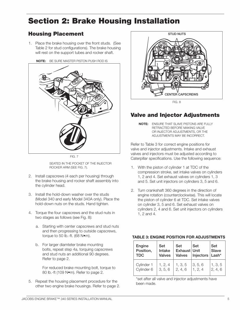
1. Place the brake housing over the front studs. (See Table 2 for stud configurations). The brake housing will rest on the support tubes and rocker shaft.
NOTE: BE SURE MASTER PISTON PUSH ROD IS
SEATED IN THE POCKET OF THE INJECTOR ROCKER ARM (SEE FIG. 7).
2. Install capscrews (4 each per housing) through the brake housing and rocker shaft assembly into the cylinder head.
3. Install the hold-down washer over the studs (Model 340 and early Model 340A only). Place the hold-down nuts on the studs. Hand tighten.
4. Torque the four capscrews and the stud nuts in two stages as follows (see Fig. 8):
a. Starting with center capscrews and stud nuts and then progressing to outside capscrews, torque to 50 lb.-ft. (68 N•m).
b. For larger diamteter brake mounting bolts, repeat step 4a, torquing capscrews and stud nuts an additional 90 degrees. Refer to page 2.
For reduced brake mounting bolt, torque to 80 lb.-ft (109 N•m). Refer to page 2.
5. Repeat the housing placement procedure for the other two engine brake housings. Refer to page 2.
Valve and Injector Adjustments
NOTE: ENSURE THAT SLAVE PISTONS ARE FULLY RETRACTED BEFORE MAKING VALVE OR INJECTOR ADJUSTMENTS, OR THE ADJUSTMENTS MAY BE INCORRECT.
Refer to Table 3 for correct engine positions for valve and injector adjustments. Intake and exhaust valves and injectors must be adjusted according to Caterpillar specifications. Use the following sequence:
1. With the piston of cylinder 1 at TDC of the compression stroke, set intake valves on cylinders 1, 2 and 4. Set exhaust valves on cylinders 1, 3 and 5. Set unit injectors on cylinders 3, 5 and 6.
2. Turn crankshaft 360 degrees in the direction of engine rotation (counterclockwise). This will locate the piston of cylinder 6 at TDC. Set intake valves on cylinder 3, 5 and 6. Set exhaust valves on cylinders 2, 4 and 6. Set unit injectors on cylinders 1, 2 and 4.
FIG. 7
FIG. 8
Engine Set Set Set SetPosition, Intake Exhaust Unit SlaveTDC Valves Valves Injectors Lash*
Cylinder 1 1, 2, 4 1, 3, 5 3, 5, 6 1, 3, 5Cylinder 6 3, 5, 6 2, 4, 6 1, 2, 4 2, 4, 6
*set after all valve and injector adjustments have been made.
TABLE 3: ENGINE POSITION FOR ADJUSTMENTS
STUD NUTS
CENTER CAPSCREWS
6 JACOBS ENGINE BRAKE™ 340 SERIES INSTALLATION MANUAL
Slave Piston Lash Adjustment
1. After the intake/exhaust valves and injectors are adjusted, set the slave piston lash (clearance). Lash adjustment must be made when exhaust valves on the cylinder to be adjusted are in the closed position. To ensure this, locate the engine with the piston of cylinder No. 1 at TDC (as described on page 3 in Section 1).
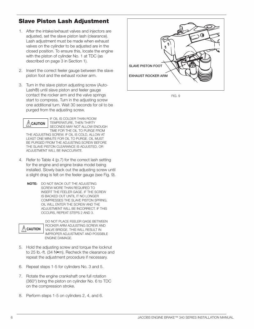
2. Insert the correct feeler gauge between the slave piston foot and the exhaust rocker arm.
3. Turn in the slave piston adjusting screw (Auto-Lash®) until slave piston and feeler gauge contact the rocker arm and the valve springs start to compress. Turn in the adjusting screw one additional turn. Wait 30 seconds for oil to be purged from the adjusting screw.
IF OIL IS COLDER THAN ROOM TEMPERATURE, THEN THIRTY SECONDS MAY NOT ALLOW ENOUGH TIME FOR THE OIL TO PURGE FROM
THE ADJUSTING SCREW. IF OIL IS COLD, ALLOW AT LEAST ONE MINUTE FOR OIL TO PURGE. OIL MUST BE PURGED FROM THE ADJUSTING SCREW BEFORE THE SLAVE PISTON CLEARANCE IS ADJUSTED, OR ADJUSTMENT WILL BE INACCURATE.
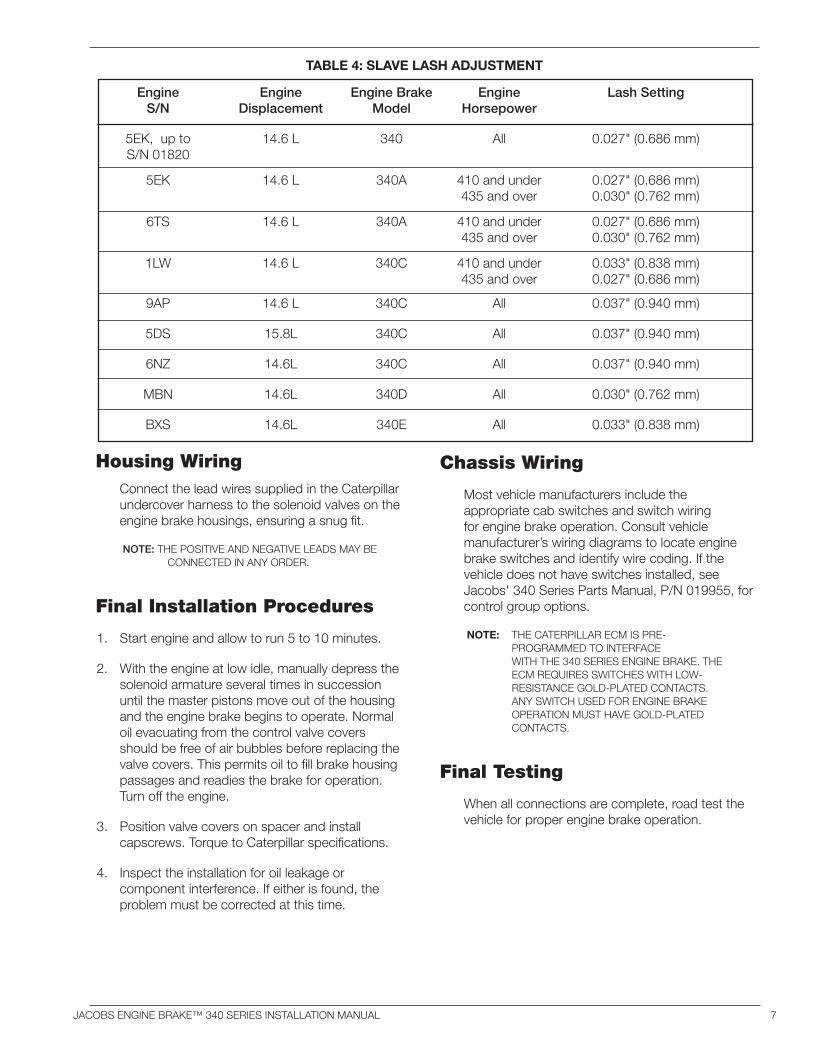
4. Refer to Table 4 (p.7) for the correct lash setting for the engine and engine brake model being installed. Slowly back out the adjusting screw until a slight drag is felt on the feeler gauge (see Fig. 9).
NOTE: DO NOT BACK OUT THE ADJUSTING SCREW MORE THAN REQUIRED TO INSERT THE FEELER GAGE. IF THE SCREW IS BACKED OUT UNTIL IT NO LONGER COMPRESSES THE SLAVE PISTON SPRING, OIL WILL ENTER THE SCREW AND THE ADJUSTMENT WILL BE INCORRECT. IF THIS OCCURS, REPEAT STEPS 2 AND 3.
DO NOT PLACE FEELER GAGE BETWEEN ROCKER ARM ADJUSTING SCREW AND VALVE BRIDGE. THIS WILL RESULT IN IMPROPER ADJUSTMENT AND POSSIBLE
ENGINE DAMAGE.
5. Hold the adjusting screw and torque the locknut to 25 lb.-ft. (34 N•m). Recheck the clearance and repeat the adjustment procedure if necessary.
6. Repeat steps 1-5 for cylinders No. 3 and 5.
7. Rotate the engine crankshaft one full rotation (360°) bring the piston on cylinder No. 6 to TDC on the compression stroke.
8. Perform steps 1-5 on cylinders 2, 4, and 6.
FIG. 9
SLAVE PISTON FOOT
EXHAUST ROCKER ARM
JACOBS ENGINE BRAKE™ 340 SERIES INSTALLATION MANUAL 7
Housing Wiring Connect the lead wires supplied in the Caterpillar
undercover harness to the solenoid valves on the engine brake housings, ensuring a snug fit.
NOTE: THE POSITIVE AND NEGATIVE LEADS MAY BE CONNECTED IN ANY ORDER.
Final Installation Procedures
1. Start engine and allow to run 5 to 10 minutes.
2. With the engine at low idle, manually depress the solenoid armature several times in succession until the master pistons move out of the housing and the engine brake begins to operate. Normal oil evacuating from the control valve covers should be free of air bubbles before replacing the valve covers. This permits oil to fill brake housing passages and readies the brake for operation. Turn off the engine.
3. Position valve covers on spacer and install capscrews. Torque to Caterpillar specifications.
4. Inspect the installation for oil leakage or component interference. If either is found, the problem must be corrected at this time.
Engine Engine Engine Brake Engine Lash Setting S/N Displacement Model Horsepower
5EK, up to 14.6 L 340 All 0.027" (0.686 mm) S/N 01820
5EK 14.6 L 340A 410 and under 0.027" (0.686 mm) 435 and over 0.030" (0.762 mm)
6TS 14.6 L 340A 410 and under 0.027" (0.686 mm) 435 and over 0.030" (0.762 mm)
1LW 14.6 L 340C 410 and under 0.033" (0.838 mm) 435 and over 0.027" (0.686 mm)
9AP 14.6 L 340C All 0.037" (0.940 mm)
5DS 15.8L 340C All 0.037" (0.940 mm)
6NZ 14.6L 340C All 0.037" (0.940 mm)
MBN 14.6L 340D All 0.030" (0.762 mm)
BXS 14.6L 340E All 0.033" (0.838 mm)
TABLE 4: SLAVE LASH ADJUSTMENT
Chassis Wiring
Most vehicle manufacturers include the appropriate cab switches and switch wiring for engine brake operation. Consult vehicle manufacturer’s wiring diagrams to locate engine brake switches and identify wire coding. If the vehicle does not have switches installed, see Jacobs' 340 Series Parts Manual, P/N 019955, for control group options.
NOTE: THE CATERPILLAR ECM IS PRE-PROGRAMMED TO INTERFACE WITH THE 340 SERIES ENGINE BRAKE. THE ECM REQUIRES SWITCHES WITH LOW-RESISTANCE GOLD-PLATED CONTACTS. ANY SWITCH USED FOR ENGINE BRAKE OPERATION MUST HAVE GOLD-PLATED CONTACTS.
Final Testing
When all connections are complete, road test the vehicle for proper engine brake operation.
8 JACOBS ENGINE BRAKE™ 340 SERIES INSTALLATION MANUAL
The Jacobs Engine Brake™ is a relatively trouble-free device. However, inspections and routine maintenance will need to be made from time to time. Use the following procedures to keep the engine brake in top condition.
This section will cover how to properly remove, clean and reinstall engine brake components. Use an OSHA-approved cleaning solvent when washing parts. Be sure to coat parts with clean engine oil when reinstalling them.
NEVER REMOVE ANY ENGINE BRAKE COMPONENT WITH ENGINE RUNNING. PERSONAL INJURY MAY RESULT.
Section 3: Engine Brake Maintenance
Theory of Operation Energizing the engine brake effectively converts
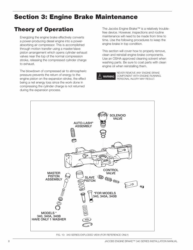
a power-producing diesel engine into a power-absorbing air compressor. This is accomplished through motion transfer using a master/slave piston arrangement which opens cylinder exhaust valves near the top of the normal compression stroke, releasing the compressed cylinder charge to exhaust.
The blowdown of compressed air to atmospheric pressure prevents the return of energy to the engine piston on the expansion stroke, the effect being a net energy loss since the work done in compressing the cylinder charge is not returned during the expansion process.
FIG. 10: 340 SERIES EXPLODED VIEW (FOR REFERENCE ONLY)
SOLENOID VALVE
AUTO-LASH®
ASSEMBLY
CONTROLVALVE
SLAVEPISTON
MASTERPISTON
ASSEMBLY
*FOR MODELS 340, 340A, 340B
MODELS *340, 340A, 340B
HAVE ONLY 1 WASHER
JACOBS ENGINE BRAKE™ 340 SERIES INSTALLATION MANUAL 9
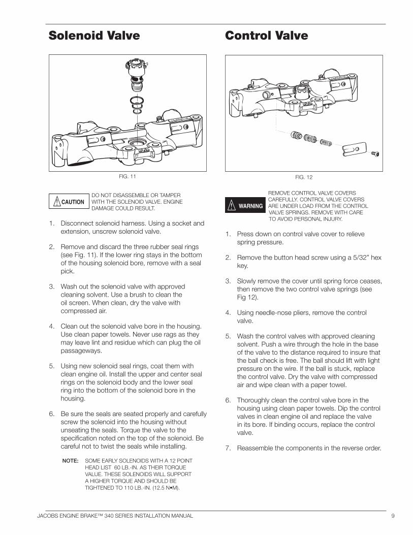
FIG. 11 FIG. 12
Solenoid Valve
DO NOT DISASSEMBLE OR TAMPER WITH THE SOLENOID VALVE. ENGINE DAMAGE COULD RESULT.
1. Disconnect solenoid harness. Using a socket and extension, unscrew solenoid valve.
2. Remove and discard the three rubber seal rings (see Fig. 11). If the lower ring stays in the bottom of the housing solenoid bore, remove with a seal pick.
3. Wash out the solenoid valve with approved cleaning solvent. Use a brush to clean the oil screen. When clean, dry the valve with compressed air.
4. Clean out the solenoid valve bore in the housing. Use clean paper towels. Never use rags as they may leave lint and residue which can plug the oil passageways.
5. Using new solenoid seal rings, coat them with clean engine oil. Install the upper and center seal rings on the solenoid body and the lower seal ring into the bottom of the solenoid bore in the housing.
6. Be sure the seals are seated properly and carefully screw the solenoid into the housing without unseating the seals. Torque the valve to the specification noted on the top of the solenoid. Be careful not to twist the seals while installing.
NOTE: SOME EARLY SOLENOIDS WITH A 12 POINT HEAD LIST 60 LB.-IN. AS THEIR TORQUE VALUE. THESE SOLENOIDS WILL SUPPORT A HIGHER TORQUE AND SHOULD BE TIGHTENED TO 110 LB.-IN. (12.5 N•M).
Control Valve
REMOVE CONTROL VALVE COVERS CAREFULLY. CONTROL VALVE COVERS ARE UNDER LOAD FROM THE CONTROL VALVE SPRINGS. REMOVE WITH CARE TO AVOID PERSONAL INJURY.
1. Press down on control valve cover to relieve spring pressure.
2. Remove the button head screw using a 5/32” hex key.
3. Slowly remove the cover until spring force ceases, then remove the two control valve springs (see Fig 12).
4. Using needle-nose pliers, remove the control valve.
5. Wash the control valves with approved cleaning solvent. Push a wire through the hole in the base of the valve to the distance required to insure that the ball check is free. The ball should lift with light pressure on the wire. If the ball is stuck, replace the control valve. Dry the valve with compressed air and wipe clean with a paper towel.
6. Thoroughly clean the control valve bore in the housing using clean paper towels. Dip the control valves in clean engine oil and replace the valve in its bore. If binding occurs, replace the control valve.
7. Reassemble the components in the reverse order.
10 JACOBS ENGINE BRAKE™ 340 SERIES INSTALLATION MANUAL
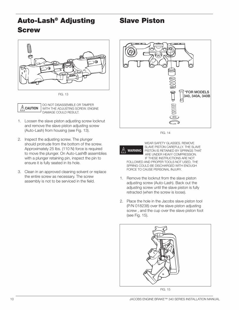
Auto-Lash® Adjusting Screw
DO NOT DISASSEMBLE OR TAMPER WITH THE ADJUSTING SCREW. ENGINE DAMAGE COULD RESULT.
1. Loosen the slave piston adjusting screw locknut and remove the slave piston adjusting screw (Auto-Lash) from housing (see Fig. 13).
2. Inspect the adjusting screw. The plunger should protrude from the bottom of the screw. Approximately 25 lbs. (110 N) force is required to move the plunger. On Auto-Lash® assemblies with a plunger retaining pin, inspect the pin to ensure it is fully seated in its hole.
3. Clean in an approved cleaning solvent or replace the entire screw as necessary. The screw assembly is not to be serviced in the field.
Slave Piston
WEAR SAFETY GLASSES. REMOVE SLAVE PISTON CAREFULLY. THE SLAVE PISTON IS RETAINED BY SPRINGS THAT ARE UNDER HEAVY COMPRESSION. IF THESE INSTRUCTIONS ARE NOT
FOLLOWED AND PROPER TOOLS NOT USED, THE SPRING COULD BE DISCHARGED WITH ENOUGH FORCE TO CAUSE PERSONAL INJURY.
1. Remove the locknut from the slave piston adjusting screw (Auto-Lash). Back out the adjusting screw until the slave piston is fully retracted (when the screw is loose).
2. Place the hole in the Jacobs slave piston tool (P/N 018238) over the slave piston adjusting screw , and the cup over the slave piston foot (see Fig. 15).
FIG. 15
FIG. 13
FIG. 14
*FOR MODELS340, 340A, 340B
JACOBS ENGINE BRAKE™ 340 SERIES INSTALLATION MANUAL 11
3. Turn the handle slowly until the slave piston retainer washer is depressed about 0.040” (1 mm), relieving pressure against the retaining ring.
4. Remove the retaining ring with retaining ring pliers. Back out the slave piston removal tool cup until the springs are loose. Remove the tool.
5. Remove all components, ensuring there is no binding or burrs. Clean in an approved cleaning solvent or replace as necessary. Check to see if the retaining ring in the slave piston foot (early models only) is intact. Inspect the piston/pushrod interface. Pitted, cracked or galled components should be replaced.
6. Lubricate all components with clean engine oil before reassembly.
NOTE: BE SURE COMPONENTS ARE REASSEMBLED IN THE PROPER ORDER (SEE FIG. 14).
7. Use the slave piston tool to reinstall piston and springs. Be sure retaining ring is placed on the retainer before screwing the slave piston tool clamp-holder down over the slave piston.
8. Compress the slave piston springs down until the retainer is about 0.040” (1 mm) below the retaining ring groove. Reinstall the retaining ring, with the sharp edge facing outward. Be sure the retaining ring is fully seated in the groove.
9. Remove the slave piston tool slowly to ensure proper seating of retaining ring.
10. Assemble the adjusting screw (Auto-Lash®) and nut. Do not tighten at this time.
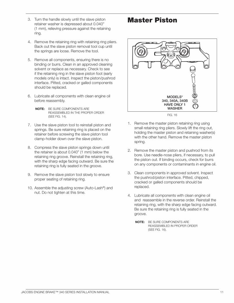
Master Piston
1. Remove the master piston retaining ring using small retaining ring pliers. Slowly lift the ring out, holding the master piston and retaining washer(s) with the other hand. Remove the master piston spring.
2. Remove the master piston and pushrod from its bore. Use needle-nose pliers, if necessary, to pull the piston out. If binding occurs, check for burrs on any components or contaminants in engine oil.
3. Clean components in approved solvent. Inspect the pushrod/piston interface. Pitted, chipped, cracked or galled components should be replaced.
4. Lubricate all components with clean engine oil and reassemble in the reverse order. Reinstall the retaining ring, with the sharp edge facing outward. Be sure the retaining ring is fully seated in the groove.
NOTE: BE SURE COMPONENTS ARE REASSEMBLED IN PROPER ORDER (SEE FIG. 16).
*FOR MODELS340, 340A, 340B
FIG. 16
MODELS*340, 340A, 340B
HAVE ONLY 1WASHER

P/N 019950 ©2005 Jacobs Vehicle Systems Printed in U.S.A. Rev. C
™Jacobs Vehicle Systems22 East Dudley Town RoadBloomfield, CT 06002
Visit us on the Internet: www.jacobsvehiclesystems.com


![[PRINT] Lash Catalogue OCT 2018 · Lash extension is the new beauty must-have for modern women. • ... Only one lash extensions is glued on one original lash, creating a natural](https://static.fdocuments.in/doc/165x107/5e1f4bb7afe75b4c2863b493/print-lash-catalogue-oct-2018-lash-extension-is-the-new-beauty-must-have-for-modern.jpg)


