Installation Owner Diagnostics - Trane Owner Diagnostics Tracer® ZN524 for water-source heat pumps...
52
Installation Owner Diagnostics Tracer ® ZN524 for water-source heat pumps Order No: CNT-SVX11A-EN Date: August 2003 CNT-SVX11A-EN
Transcript of Installation Owner Diagnostics - Trane Owner Diagnostics Tracer® ZN524 for water-source heat pumps...

InstallationOwnerDiagnostics
Tracer® ZN524 for water-source heat pumps
Order No: CNT-SVX11A-EN Date: August 2003
CNT-SVX11A-EN

2 UV-SVN001-EN
Notice
Notice
Warnings and Cautions appear at appropriate sections throughout this manual.Read these carefully.
- Indicates a potentially hazordous situation which, if not avoided, could result in death or serious injury
WARNING
CAUTION - Indicates a potentially hazordous situation which, if not avoided, could result in minor or moderate injury. It may also be used to alert against unsafe practices.
CAUTION - Indicates a situation that may result in equipment or property damage only accidents.

Contents
CNT-SVX11A-EN 3
Start-up Procedures 4General Information 5Control Circuit Board Features 6Control Features 7Communication Configurations 8Installation and Wiring 10Typical Wiring Diagram— 18
Waterside Ecomomizer
Typical Wiring Diagram— 19Hot Gas Reheat
Configuration 20Location Identifier 23Unit Operation 24Troubleshooting 32Replacing Circuit Boards 42Appendix 43Appendix—Binary Configuration 44Appendix—Unit Operation 45Appendix—Data Lists 47Appendix—Location Identifier 48
Start-up Procedures
4 CNT-SVX11A-EN
Installation of New Units
WARNINGHazardous Voltage!Disconnect all electric power, includingremote disconnects before servicing.Follow proper lockout/tagout proce-dures to ensure the power can not beinadvertently energized. Failure to dis-connect power before servicing couldresult in death or serious injury.
1. Follow all instruction for installationof the water-source heat pump asdetailed in the unit’s installation guide.(Installation Operation Diagnosticsmanual).
2. Disconnect power or disable the cir-cuit breaker to unit.
3. Run communication link wire whenrequired. (See wiring diagram in theunit).
4. Install zone sensor when required.(See wiring diagram in the unit andzone sensor submittals).
5. Reapply power.
6. Check for GREEN Status LED opera-tion to ensure power has been madeto the TracerTM ZN524 unit controller.
7. Check for YELLOW Comm LED opera-tion to help ensure communication hasbeen made to the Tracer ZN524 unitcontroller when applicable.
8. Write the Unit Identification number,using the IDENTIFICATION TAG on theunit, in the Appendix of this document,or on building plans for future locationuse.
Power Up SequenceManual output test can be initiated atany time in the power up sequence orduring normal operation.
When 24 VAC power is initially appliedto the controller, the followingsequence occurs:
1. Green Status LED turns on.
2. All outputs are controlled Off.
3. The controller reads input values todetermine initial values.
4. Stand-alone control is assumedunless occupancy data is communicat-ed.
5. Random start timer expires (5 to 30seconds, random).
6. Power-up control Wait feature isapplied. When power up control Wait isenabled, the controller waits 2-minutesto allow ample time for communicatedcontrol data to arrive. If, after 2-min-utes, the controller does not receive acommunicated occupancy request, theunit assumes standalone operation.
7. All valves and damper calibrateclosed.
8. Normal operation begins after 290(potentially) seconds have passed.
Note: Manual output test can beinitiated at any time.

General Information
CNT-SVX11A-EN 5
Tracer® ZN524 Overview
The Trane Tracer® ZN524 controller is afactory-installed and commissioned,direct-digital controller (DDC) offeringfor single or dual compressor water-source heat pump systems. (See Figure1: “Tracer ZN524 Control Board”)
Trane offers a complete solution tospace comfort control with the flexibili-ty of Integrated Comfort System (ICS)and stand-alone control packages. TheICS control package combines HVACequipment and building managementinto one environmental comfort sys-tem.
Integrating the Tracer ZN524 on water-source heat pumps and tying them to aTracer Summit® system will provide acomplete building management sys-tem. The stand-alone control packageoffers the features and functionality ofthe direct digital control without afront-end building automation system,while providing future considerationsfor ICS.
Equipment problems can often be diag-nosed on each unit without having toaccess the unit componets. These diag-nostics can be received remotely via amodem with a Tracer Summit buildingautomation system, thus reducing thenumber of actual on-site service calls;through the Rover® service tool con-nected to a communication jack locatedinside the Trace zone sensor; or con-nected to the unit.
The Tracer ZN524 is factory-mounted,tested, wired, configured and commis-sioned for the selected application.
The Tracer ZN524 configuration hasflexible point and product configura-tions. For example, with point configu-ration, a specific binary point can beconfigured to accept input from either atime clock or some type of genericdevice.
Figure 1: Tracer ZN524 control board
Controller Circuit Board and Features
6 CNT-SVX11A-EN
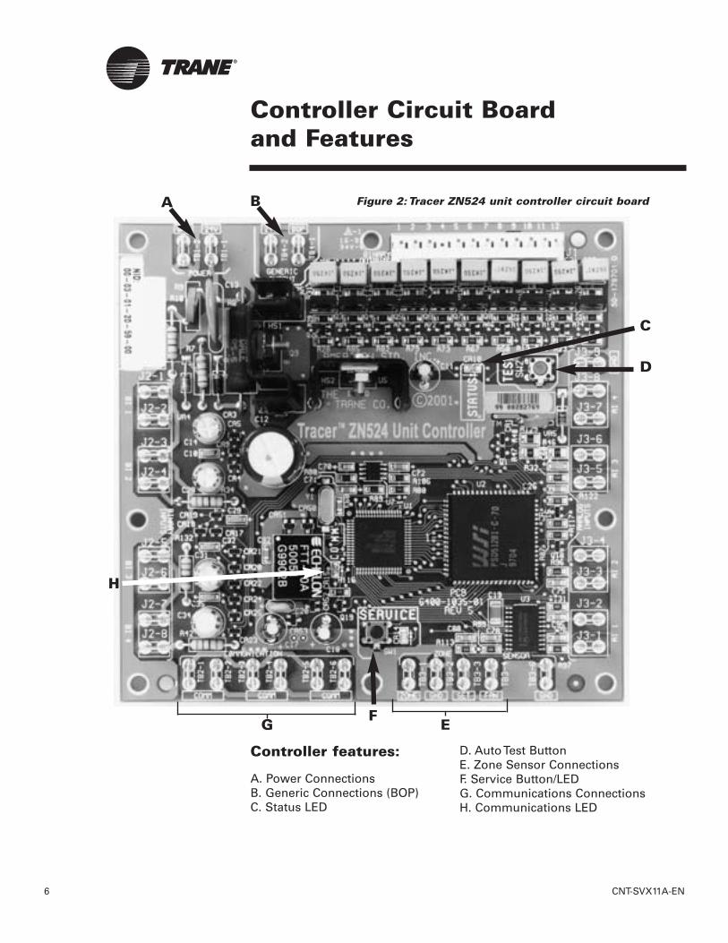
Figure 2: Tracer ZN524 unit controller circuit boardA B
E
D
C
H
FG
Controller features:
A. Power ConnectionsB. Generic Connections (BOP)C. Status LED
D. Auto Test ButtonE. Zone Sensor ConnectionsF. Service Button/LEDG. Communications ConnectionsH. Communications LED
CNT-SVX11A-EN 7
Controller Features
Each Tracer ZN524 unit controller circuitboard is equipped with enhancementsto help facilitate service, testing, anddiagnosis.Each board has:• Manual test button,• Status LED,• Communication status LED,• Service button,• Quick terminal connectors, and• Easy to read screen printing. (See
Figure 2: Page 6).
ServiceThe Trane Tracer ZN524 unit controller isserviced using Rover®, the softwareservice tool. Rover is designed to sup-port the Tracer ZN524 unit controller ona single or dual compressor water-source heat pump.
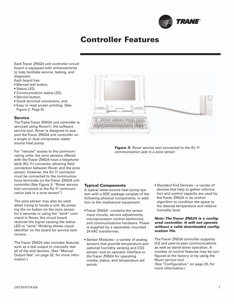
For “remote” access to the communi-cating units, the zone sensors offeredwith the Tracer ZN524 have a telephonestyle (RJ-11) connector allowing fieldconnection between Rover and the zonesensor; however, the RJ-11 connectormust be connected to the communica-tions terminals on the Tracer ZN524 unitcontroller.(See Figure 3: “Rover servicetool connected to the RJ-11 communi-cation jack in a zone sensor”)
The zone sensor may also be usedwhen trying to locate a unit. By press-ing the on button on the zone sensorfor 5 seconds or using the “wink” com-mand in Rover, the circuit boardreceives the signal causing the statusLED to “wink.” Winking allows visualidentifier on the board for service tech-nicians.
The Tracer ZN524 also includes featuressuch as a test output to manually testall of the end devices. (See “ManualOutput Test” on page 32, for more infor-mation.)
Typical ComponentsA typical water-source heat pump sys-tem with a DDC package consists of thefollowing physical components, in addi-tion to the mechanical equipment:
• Tracer ZN524—contains the sensor input circuits, service adjustments, microprocessor control electronics, and communications hardware. Poweris supplied by a separately mounted 24 VAC transformer.
• Sensor Modules—a variety of analog sensors that provide temperature and optional humidity sensing and CO2 sensor; and an operator interface to the Tracer ZN524 for operating modes, status, and temperature setpoints.
• Standard End Devices—a variety of devices that help to gather informa-tion and control capacity are used by the Tracer ZN524 in its control algorithm to condition the space to the desired temperature and relative humidity level.
Note: The Tracer ZN524 is a config-ured controller. It will not operatewithout a valid downloaded config-uration file.
The Tracer ZN524 controller supportsICS and peer-to-peer communicationsas well as stand-alone operation. Anumber of control features may be con-figured at the factory or by using theRover service tool. (See “Configuration” on page 20, formore information.)
Figure 3: Rover service tool connected to the RJ-11 communication jack in a zone sensor

Communication Configurations
8 CNT-SVX11A-EN
Integrated Comfort SystemNote: The Tracer ZN524 controllermay only be used with TracerSummit version 11.0 or greaterwith a Comm5 communicationscard.Water-source heat pumps can operateas part of a large building automationsystem controlled by Tracer Summit.The Tracer ZN524 is linked directly tothe Tracer Summit via a twisted paircommunication wire. Each TracerSummit building automation systemcan connect to a maximum of 120Tracer ZN524 controllers.
Communications link wireThe ICS system allows for completecommunication with the water-sourceheat pumps via Tracer ZN524 unit con-troller. All points connected to theTracer ZN524 may be observed fromthe Tracer Summit front-end controller.The Tracer Summit can also initiate analarm on a loss of performance orequipment malfunctions.
The ICS system also allows all of thewater-source heat pumps to share infor-mation without the presence of hard-wired sensors at each unit. Some typi-cal shared points include outside airtemperature, entering water tempera-ture, and occupancy schedules.
Peer-to-Peer CommunicationsOn a peer-to-peer communication sys-tem, multiple Tracer ZN524 controllersmay share data, via a twisted pair com-munication wire, without the need for aTracer Summit system. (See Figure 5:“Peer-to-peer communication connec-tions”)
Peer-to-peer communications allowsfeatures such as master/slave opera-tion, in which multiple units operate offof a single zone sensor. This is typicallyseen in large spaces requiring multipleunits.
The Rover service tool is required to setup peer-to-peer communications.
Figure 4: Communications link wire
Figure 5: Peer-to-peer communication connections
Twisted pair wire used ininstallation of controller inwater-source heat pump
CNT-SVX11A-EN 9
Communication InterfaceImportant! To help ensure optimalperformance of the Rover servicetool, please use the latest version.To obtain the latest version con-tact your local Trane sales repre-sentative or service technician.
Note: Refer to the Tracer systemmanuals for more information oncommunications.
The Tracer ZN524 communicates viaComm5 (LonTalk) to a building man-agement system, the Rover servicetool, and other unit controllers on thecommunications link. Each TracerZN524 requires a unique address forthe system to operate properly. EveryTracer ZN524 has this address (NeuronID) embedded in the microprocessor,which eliminates the need for field-addressing of the units. Each unit alsoships from the factory with a unit iden-tification tag. (See “Location Identifier”on page 23, for more information.)
Building automation systemTrane offers a state-of the art front-endbuilding automation system designedto coordinate and monitor Trane equip-ment and controllers: Tracer Summit.The Tracer Summit system allows theuser to monitor and/or change TracerZN524:• status, parameters, sensor data,
diagnostics, and internal variables; and
• setpoints, operating modes, and outputs.
Service toolTrane also offers a service tool to workin conjunction with the Tracer Summitsystem or with peer-to-peer and stand-alone systems: the Rover service tool.
Communication to the Tracer ZN524, ormultiple controllers, can also be accom-plished by using the ICS software serv-ice tool.
A personal computer running Rovermay be directly connected to a stand-alone Tracer ZN524; connected to thecommunications jack in the Trane zonesensor; or connected to a communicat-
ing unit’s Tracer ZN524unit controller, to accessall of the units on a com-municating link.
Rover allows the user tointerface with the TracerZN524, but will not allowany advanced control(e.g. equipment schedul-ing or trending). To pur-chase a copy of the ICSsoftware service tool,contact the BAS depart-ment at your local Tranedealer.
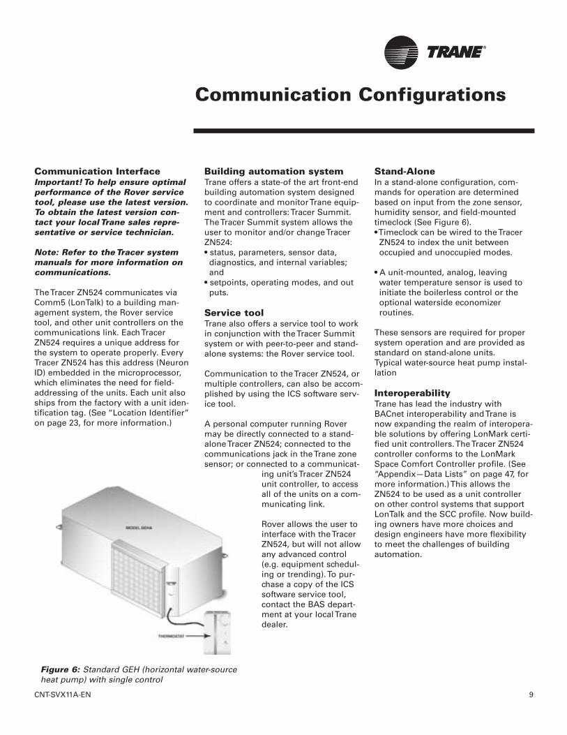
Stand-AloneIn a stand-alone configuration, com-mands for operation are determinedbased on input from the zone sensor,humidity sensor, and field-mountedtimeclock (See Figure 6).• Timeclock can be wired to the Tracer
ZN524 to index the unit between occupied and unoccupied modes.
• A unit-mounted, analog, leavingwater temperature sensor is used to initiate the boilerless control or the optional waterside economizer routines.
These sensors are required for propersystem operation and are provided asstandard on stand-alone units.Typical water-source heat pump instal-lation
InteroperabilityTrane has lead the industry withBACnet interoperability and Trane isnow expanding the realm of interopera-ble solutions by offering LonMark certi-fied unit controllers. The Tracer ZN524controller conforms to the LonMarkSpace Comfort Controller profile. (See“Appendix—Data Lists” on page 47, formore information.) This allows theZN524 to be used as a unit controlleron other control systems that supportLonTalk and the SCC profile. Now build-ing owners have more choices anddesign engineers have more flexibilityto meet the challenges of buildingautomation.
Communication Configurations
Figure 6: Standard GEH (horizontal water-sourceheat pump) with single control

10 CNT-SVX11A-EN
Specifications
DimensionsTracer ZN524 board and mountinghardware:• Height: 5.25 inches (133 mm.)• Width: 5.50 inches (140 mm)• Depth: 2.25 inches (57 mm)
Power Requirements• 18 to 32 VAC (24 VAC nominal)• 50 or 60 Hz• 570 mA AC
Operating Environment• 32° to 140°F (0× to 60°C)• 5% to 95% relative humidity,
non-condensing
Storage Environment• -40° to 185°F (-40° to 85°C)• 5% to 95% relative humidity, non-
condensing
Agency Listings• UL and CUL 916 Energy Management
System• Agency Compliance IEC 1000-4-2
(ESD), IEC 1000-4-4(EFT), IEC 1000-4-5 (Surge)
Installation & Wiring
Figure 7: Tracer ZN524 circuit board schematic
Installation & Wiring
CNT-SVX11A-EN 11
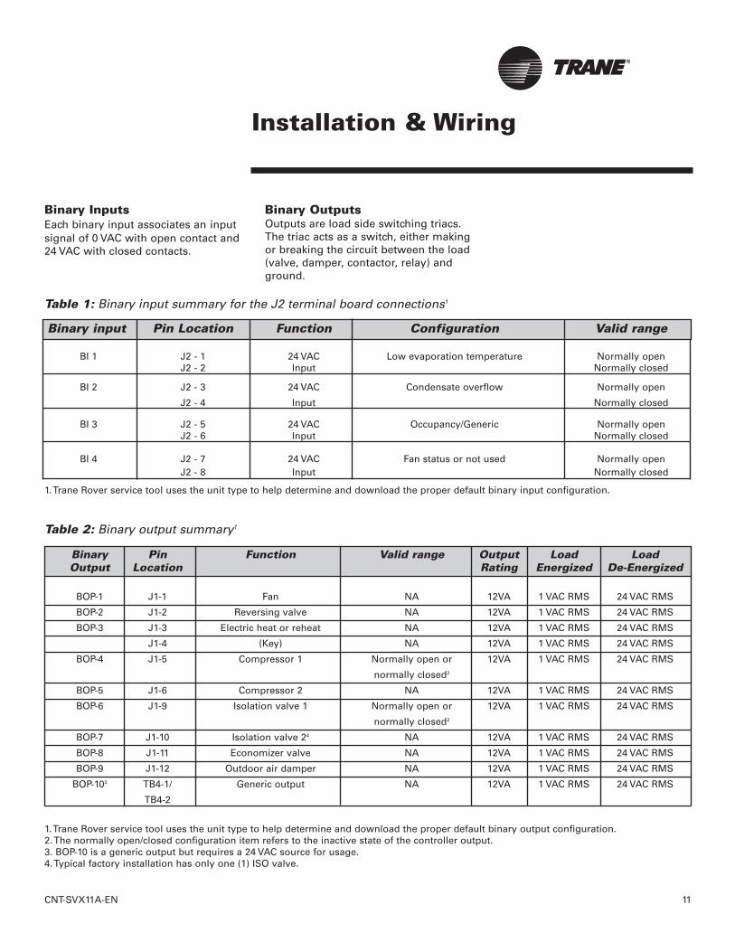
Binary input Pin Location Function Configuration Valid range
BI 1 J2 - 1 24 VAC Low evaporation temperature Normally openJ2 - 2 Input Normally closed
BI 2 J2 - 3 24 VAC Condensate overflow Normally open
J2 - 4 Input Normally closed
BI 3 J2 - 5 24 VAC Occupancy/Generic Normally openJ2 - 6 Input Normally closed
BI 4 J2 - 7 24 VAC Fan status or not used Normally openJ2 - 8 Input Normally closed
1. Trane Rover service tool uses the unit type to help determine and download the proper default binary input configuration.
Binary InputsEach binary input associates an inputsignal of 0 VAC with open contact and24 VAC with closed contacts.
Binary OutputsOutputs are load side switching triacs.The triac acts as a switch, either makingor breaking the circuit between the load(valve, damper, contactor, relay) andground.
Table 1: Binary input summary for the J2 terminal board connections1
Binary Pin Function Valid range Output Load LoadOutput Location Rating Energized De-Energized
BOP-1 J1-1 Fan NA 12VA 1 VAC RMS 24 VAC RMS
BOP-2 J1-2 Reversing valve NA 12VA 1 VAC RMS 24 VAC RMS
BOP-3 J1-3 Electric heat or reheat NA 12VA 1 VAC RMS 24 VAC RMS
J1-4 (Key) NA 12VA 1 VAC RMS 24 VAC RMS
BOP-4 J1-5 Compressor 1 Normally open or 12VA 1 VAC RMS 24 VAC RMS
normally closed2
BOP-5 J1-6 Compressor 2 NA 12VA 1 VAC RMS 24 VAC RMS
BOP-6 J1-9 Isolation valve 1 Normally open or 12VA 1 VAC RMS 24 VAC RMS
normally closed2
BOP-7 J1-10 Isolation valve 24 NA 12VA 1 VAC RMS 24 VAC RMS
BOP-8 J1-11 Economizer valve NA 12VA 1 VAC RMS 24 VAC RMS
BOP-9 J1-12 Outdoor air damper NA 12VA 1 VAC RMS 24 VAC RMS
BOP-103 TB4-1/ Generic output NA 12VA 1 VAC RMS 24 VAC RMS
TB4-2
Table 2: Binary output summary1
1. Trane Rover service tool uses the unit type to help determine and download the proper default binary output configuration.2. The normally open/closed configuration item refers to the inactive state of the controller output.3. BOP-10 is a generic output but requires a 24 VAC source for usage.4. Typical factory installation has only one (1) ISO valve.

12 CNT-SVX11A-EN
Installation & Wiring
Description Terminals Function Range
Zone TB3-1 Space temperature input 5× to 122×F(-15× to 50×C)
Ground TB3-2 Analog ground NASet TB3-3 Local setpoint input 40× to 115×F
(4.4× to 46.1×C)Fan TB3-4 Fan switch input 4821 to 4919 � (Off)
2297 to 2342 � (Auto)15137 to 16463 � (High)
Ground TB3-6 Analog ground NA
Analog Inputs
Table 3: Analog Inputs (Zone Sensor)
Analog input Terminal Function Range
AI 1 J3 - 1 Entering water temperature or -40 to 2120F (-400 to 1000C)J3 - 2 outside air temperature -40 to 2120F (-400 to 1000C)
AI 2 J3 - 3 Discharge air temperature -40 to 2120F (-400 to 1000C)J3 - 4
AI 3 J3 - 5 Leaving water temperature -40 to 2120F (-400 to 1000C)J3 - 6
AI 4 J3 - 7 Universal 4-20mA input 4-20maJ3 - 8 Humidity 0-100%J3 - 9 CO2 0 - 2000 ppm
Table 4: Analog Inputs with terminal connections1,2
1. Trane Rover service tool uses the unit type to help determine and download the proper default analog input configuration.2. Analog input 3 (AI 3) configured as generic temperature input does not affect unit operation. When configured, the TracerTM ZN524 unit con-troller communicates the generic temperature value to Rover or Tracer Summit and displays it as generic temperature.
CNT-SVX11A-EN 13
Installation & Wiring
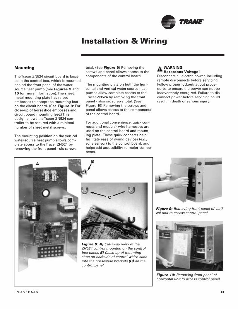
Mounting
The Tracer ZN524 circuit board is locat-ed in the control box, which is mountedbehind the front panel of the water-source heat pump (See Figures 9 and10 for more information). The sheetmetal mounting plate has raisedembosses to accept the mounting feeton the circuit board. (See Figure 8: Forclose-up of horseshoe embosses andcircuit board mounting feet.) Thisdesign allows the Tracer ZN524 con-troller to be secured with a minimalnumber of sheet metal screws.
The mounting position on the verticalwater-source heat pump allows com-plete access to the Tracer ZN524 byremoving the front panel - six screws
total. (See Figure 9) Removing thescrews and panel allows access to thecomponents of the control board.
The mounting plate on both the hori-zontal and vertical water-source heatpumps allow complete access to theTracer ZN524 by removing the frontpanel - also six screws total. (SeeFigure 10) Removing the screws andpanel allows access to the componentsof the control board.
For additional convenience, quick con-nects and modular wire harnesses areused on the control board and mount-ing plate. These quick connects helpfacilitate ease of wiring devices (e.g.,zone sensor) to the control board, andhelps add accessibility to major compo-nents.
WARNINGHazardous Voltage!
Disconnect all electric power, includingremote disconnects before servicing.Follow proper lockout/tagout proce-dures to ensure the power can not beinadvertently energized. Failure to dis-connect power before servicing couldresult in death or serious injury.
Figure 8: A) Cut-away view of theZN524 control mounted on the controlbox panel. B) Close-up of mountingshoe on backside of control which slideinto the horseshoe brackets (C) on thecontrol panel.
Figure 9: Removing front panel of verti-cal unit to access control panel.
Figure 10: Removing front panel ofhorizontal unit to access control panel.
A
C
B

14 CNT-SVX11A-EN
Installation & Wiring
Wiring
Live Electrical Components!During installation, testing, servicing,and troubleshooting of this product, itmay be necessary to work with liveelectrical components. Have a qualifiedlicensed electrician or other individualwho has been properly trained in han-dling live electrical components per-form these tasks. Failure to follow allelectrical safety precautions whenexposed to live electrical componentscould result in death or serious injury.
Use Copper Conductors Only!Unit terminals are not designed toaccept other types of conductors.Failure to use copper conductors mayresult in equipment damage.
Important! All wiring must complywith state, local, and federalguidelines. Contact the appropriatelocal agency for further information.
Important! Wires for temperaturesensors, communication lines, 24VAC, and contact closure sensinginputs should not be bundled withor run near high voltage wiring.
• To prevent damage to the unit, refer tothe diagram provided on the unit’s inside access panel for specific wiring information. Most control componentsare factory-wired. Zone sensors and communication wiring is to be installed by the contractor.
• Power wiring must be separated from the Tracer ZN524 and all low voltage wires. External input wires should be run in separate conduits from high voltage wires.
• Wires connected to pin headers should be formed and routed so as to cause minimum strain on the Tracer ZN524 connector.
• A minimum of 1.5" clearance (from thepin centerline) for wires up to 16 AWGis recommended for bending and forming wires.
• All sensor and input circuits are at or near ground potential. Do not connectany sensor or input circuit to an external ground connection.
• A close-coupled ground connection is
required for the Tracer ZN524.• Table 5: Tracer ZN524 Wiring
Requirements, shows Tracer ZN524 wire types and lengths.
PowerThe Tracer ZN524 controller is poweredby 24 VAC. (See Table 5: “Tracer ZN524wiring requirements”)A total of two 1/4-inch quick-connect terminals are provid-ed for 24 VAC connection to the board.
Figure 10: Power connections to the Tracer ZN524 unit controller
Application Wire Type Length
Contact 18 AWG Up to Closure 1000 ft.
24 VAC 16-22 AWG Up to 1000 ft.
Zone 16-22 AWG Up toSensor 200 ft.
Communications Belden 8760 Up to or 5000 ft.
equivalent
ZN524
WARNING
CAUTION
Table 5:Tracer ZN524 wiringrequirements

CNT-SVX11A-EN 15
Installation & Wiring
Installing the Wall-MountedZone Sensor (Optional)
Zone sensor location is an importantelement of effective room control andcomfort.
The best sensor location is typically ona wall, remote from the HVAC unit.Readings at this location assure that thedesired setpoint is achieved across thespace, not just near the unit itself.
Note: It may be necessary tosubdivide the zone with multipleunits to ensure adequate controland comfort throughout the space.
The following are typical areas wherethe zone sensor should not bemounted:• Near drafts or “dead spots” (e.g.,
behind doors or corners);• Near hot or cold air ducts;• Near radiant heat (e.g., heat emitted
from appliances or the sun);• Near concealed pipes or chimneys;• On outside walls or other non-
conditioned surfaces; or
• In air flows from adjacent zones or other units.
The communications link is not con-nected in the factory. Communicationscould be wired to the wall-mountedsensor if desired.
Figure 11: Proper zone sensor placement

16 CNT-SVX11A-EN
Installation & Wiring
Zone Sensor FeaturesFan Switch (Optional)
The zone sensor fan switch providesthe controller with an occupied (andoccupied standby) fan request signal ofoff or auto. If the fan control request iscommunicated to the controller, thecontroller ignores the hardwired fanswitch input and uses the communicat-ed value. The zone sensor fan switchsignal can be enabled or disabledthrough configuration in the ZN524controller.
ON or CANCEL Buttons
Momentarily pressing the on buttonduring unoccupied mode places thecontroller in occupied bypass mode for120 minutes. You can adjust the numberof minutes in the unit controller config-uration using Trane’s service tool,Rover. The controller remains in occu-pied standby mode until the overridetimer expires or until the cancel buttonis pressed.
Communication Jack
Use the RJ-11 communication jack asthe connection point from Rover to thecommunication link (when the commu-nication jack is wired to the communi-cation link at the controller). By access-ing the communication jack via Rover,entrance to all controllers on the linkmay be gained.
Table 6: Zone Sensor Options
Part number:X13510628010
Description:• Space temperature
(0.2 C resolution)• Internal setpoint• Communication jack• Vertical case with Trane logo
Part number:X13510606010
Description:• Space temperature
(0.2 C resolution)• External setpoint• Communication jack• Vertical case with Trane logo

CNT-SVX11A-EN 17
Installation & Wiring
Table 6: Zone Sensor Options - continued
Part number:X13510606020
Description:• Space temperature
(0.2 C resolution)• ON and CANCEL buttons• External setpoint• Communication jack• Vertical case with Trane logo
Part number:X13510635010
Description:• Space temperature
(0.2 C resolution)• ON and CANCEL buttons• Fan switch (OFF and AUTO)• External setpoint• Communication jack• Vertical case with Trane logo
18 CNT-SVX11A-EN
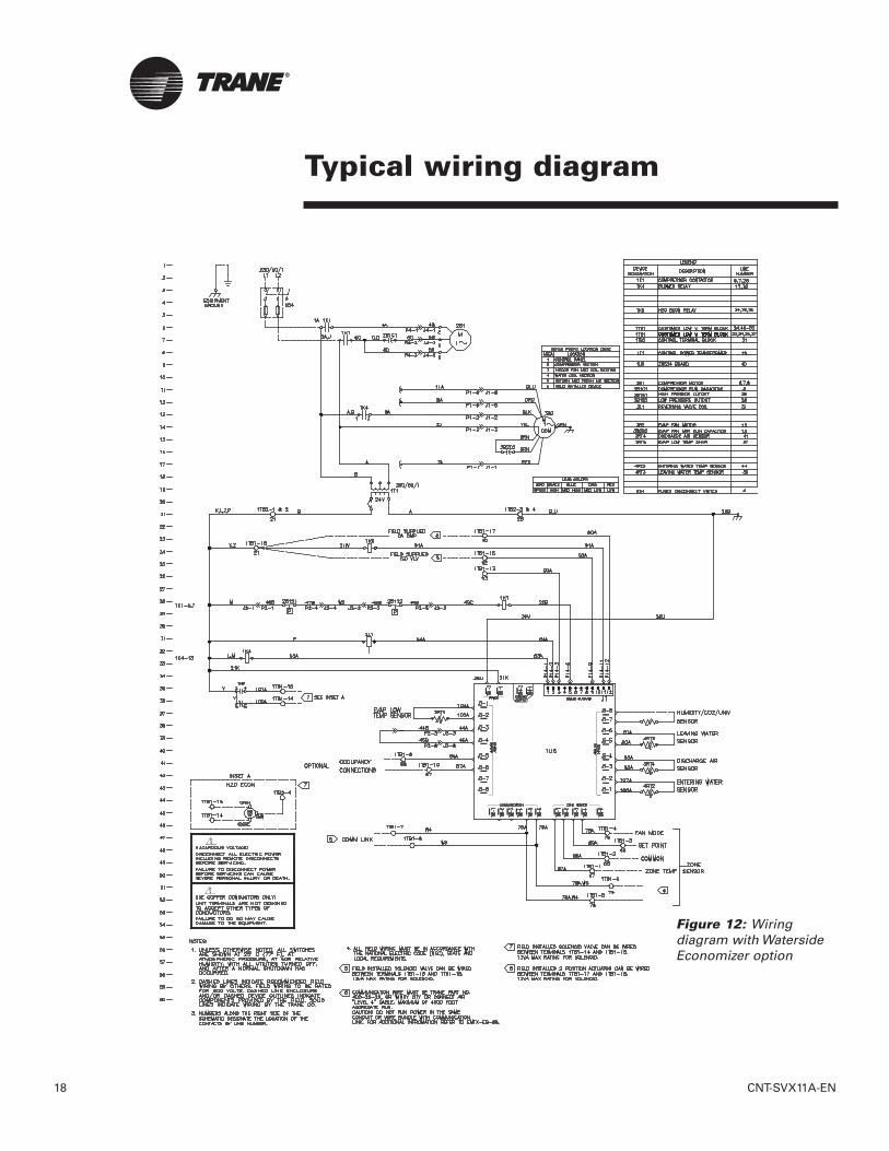
Typical wiring diagram
Figure 12: Wiring diagram with WatersideEconomizer option
CNT-SVX11A-EN 19
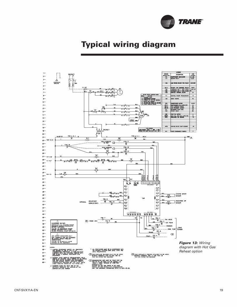
Typical wiring diagram
Figure 13: Wiring diagram with Hot GasReheat option

20 CNT-SVX11A-EN
Configuration
Table 7:Typical Applications Supported1
Trane configures the Tracer® ZN524Unit Controller at the factory per theselected unit configuration. The con-troller is applied to water-source heatpumps designed for cooling only orstandard heat pump usage, in both sin-gle or dual-compressor design. Thecontroller also supports the useage of
water-side economizer, hot gas reheat,electric heat or boilerless units. Table 7defines the configuration options sup-ported by the ZN524 controls.
Configurable parameters
Rover service tool uses the unit type todetermine and download many otheraspects of the unit configuration, suchas the default analog input configura-tion, the default binary input configura-tion, and the default binary output con-figuration.
Cooling source• DX Cooling• Waterside economizer
Heating source• None• Electric heat • DX Heating
Unit Water-side Hot Gas Electric BoilerlessEconomizer Reheat Heat
Cooling Only XX
XX XX X
Heat XPump X
XX
X XX XX X
1. Information applies to both single or dual compressor design

CNT-SVX11A-EN 21
Configuration
Fan configuration Default Valid range
Fan operation in heating Continuous Continuous1
Cycling with capacity
Fan operation in cooling Continuous Continuous (during occupied) Cycling with capacity (unoccupied)
Number of fan speeds One 1
Configurable fan speed heating High Off, high, auto
Configurable fan speed cooling High Off, high, auto
Zone sensor fan switch Enable Disable or enable
Table 8: Fan configuration ranges
Setpoint Default Valid range
Occupied heating setpoint 71°F 40 to 115°F
Occupied cooling setpoint 74°F 40 to 115°F
Occupied standby heating setpoint 67°F 40 to 115°F
Occupied standby cooling setpoint 78°F 40 to 115°F
Unoccupied heating setpoint 60°F 40 to 115°F
Unoccupied cooling setpoint 85°F 40 to 115°F
Heating setpoint low limit1 40°F 40 to 115°F
Cooling setpoint low limit1 40°F 40 to 115°F
Heating setpoint high limit1 105°F 40 to 115°F
Cooling setpoint high limit 1 110°F 40 to 115°F
Thumbwheel setpoint Enable Disable or enable
Economizer setpoint 50°F 40 to 100°F
Humidity setpoint 60% 0 to 100%
Table 9: Setpoint defaults
1. The heating and cooling setpoint high and low limits only apply to the occupied and occupied standby setpoints and are not applied to theunoccupied setpoints.
Table 10: Discharge air limit ranges
Default Valid Range
Low Limit1 45°F 30 to 50°F
1. The low limit is the temperature at which the controller shuts down the unit to prevent the coil from frosting.
1. Fan will cycle when unoccupied

22 CNT-SVX11A-EN
Configuration
Table 11: Bypass timer range
Default Valid Range
Occupancy bypass timer1 120 minutes 30 to 240 minutes( 1-minute resolution)
1. The occupied bypass timer is used for timed override applications.
Occupied Bypass Timer
Table 12: Control wait timer
Default Valid Range
Power up control wait (2 minutes) 120 seconds Disable or enable
Power-up Control Wait
Table 13: Maintenance timer range1
Default Valid Range
Maintenance timer 0 0 to 10,000 hours
Maintenance Timers
1. Based on fan run hours.

CNT-SVX11A-EN 23
Location Identifier
Unit Identification Tag
The unit identification tag is factorymounted and provided for easy identifi-cation of an installed unit. It containsmodel number, tagging, and locationinformation.
The unit identification tag remains per-manently affixed to the unit for identifi-cation purposes. The bottom portion ofthe tag provides pertinent informationthat can be written to in building plansor in the “Appendix—LocationIdentifier” on page 48.This providesidentification history about the unit’slocation for quick reference.
These tags provide information about:
• unit serial number (A)
• NID (neuron identification number)—The NID is similar to the serial numberof the unit but is specific to the identifi-cation of the Tracer ZN524 unit con-troller circuit board (B)
• unit location—The location identifica-tion is a customer defined, clearEnglish description, of the unit’s physi-cal location. This is a 27 characterdescription, including spaces, of thelocation. For example, if the locationidentification for a unit is “ConferenceRoom 101”, the ZN524, Rover (the TraneLoop Controller service tool), and TracerSummit, will recognize this clearEnglish description. (C)
If location identification is not defined,it will default to the unit serial number.This unit identification tag providessome information so the user has mul-tiple references to the unit. The blanklocation is provided for field modifica-tion in case the unit is moved from theinitial location.
Winking
Winking a device causes the green sta-tus LED on the device selected to blinkat a rate of twice per second forapproximately 10 seconds. This featureis useful when a discrepancy in devicelocation exists. As part of the trou-bleshooting process, one person canwink the device while another canobserve the blinking and verify thedevice’s physical location.
Important! If the status LED on theZN524 does not blink, the devicemay not be communicating or itmay not be the device you selectedaccording to the stored address.A Tracer ZN524 unit controller may beset to wink by pressing zone sensor Onbutton for 5 seconds and using Rover,Trane’s communication service tool orthe Tracer Loop Controller.
Figure 14: Water-source heat pump unit identification tag.
A
CB

24 CNT-SVX11A-EN
Unit Operation
Power-Up
When 24 VAC is initially applied to thecontroller, the following sequence ofevents occurs:
• Green status LED turns on.• All outputs are controlled OFF.• The controller reads input values to
determine initial values.• Random-start timer expires
(5 to 30 seconds).• When POWER-UP CONTROL WAIT is
enabled, the controller waits 0-120 seconds (depending on configuration)to allow ample time for communicated control data to input. Ifthe controller does not receive communi-cated information, standalone control is assumed.
• All valves and dampers are closed.• NORMAL operation begins.
Occupancy
The valid occupancy modes for theTracer ZN524 controller are:
• OCCUPIED - Normal operating mode for occupied spaces or daytime operation.
• UNOCCUPIED - Normal operating modefor unoccupied spaces or nighttime operation.
• OCCUPIED STANDBY - Mode used to reduce the heating and cooling demands during the occupied hours when the space is vacant or isunoccupied.
• OCCUPIED BYPASS -Used to temporarily transition the unit from unoccupied to occupied operation.
The occupancy mode can be hardwiredto the controller via the occupancybinary input or communicated to thecontroller.
OCCUPIED modeWhen the controller is in the OCCUPIED
mode, the unit attempts to maintain thespace temperature at the active occu-
pied heating or cooling setpoint.OCCUPIED mode is the default mode ofthe Tracer ZN524 controller.
UNOCCUPIED modeWhen the controller is in the UNOCCUPIED mode, the unit attempts tomaintain space temperature at thestored unoccupied heating or coolingsetpoint (i.e., configurable throughTracer Summit or the Rover servicetool) regardless of the presence of ahardwired or communicated setpoint.When the space temperature exceedsthe stored unoccupied setpoint, thecontroller brings on 100% of the pri-mary heating or cooling capacity.
The UNOCCUPIED mode can be initiatedthrough a hardwired signal to the occu-pancy binary input or by a communi-cated request.
OCCUPIED STANDBY modeThe OCCUPIED STANDBY mode allows theunit to operate at a heating or coolingsetpoint between the occupied andunoccupied setpoints to help maintainthe environment while decreasing ener-gy consumption.
This mode can decrease the energyconsumption for heating or coolingduring brief periods of vacancy in thespace. Unit operation in this mode issimilar to the occupied mode except forthe different heating and cooling set-points.
The OCCUPIED STANDBY mode is initiatedonly when occupancy is communicatedto the Tracer ZN524 controller and thehardwired signal to the occupancyinput is calling for unoccupied opera-tion.
OCCUPIED BYPASS modeThe OCCUPIED BYPASS mode is used totransition the unit from the UNOCCUPIED
mode to the occupied mode for a peri-od of time from 0 to 4 hours (config-urable through Rover. Default=2 HRS).
The controller can be placed in OCCUPIED BYPASS mode by either com-municating an occupancy request ofbypass or by using the TIMED OVERRIDE
(i.e., ON) button on the Trane zone sen-sor.
ON and CANCEL ButtonsSome Trane zone sensors have ON andCANCEL buttons for timed overrideoperation. Pressing the On button onthe zone sensor when the unit is in theUNOCCUPIED mode initiates the OCCUPIED BYPASS mode and initializesthe bypass timer. The cancel button isused to send the unit back into UNOCCUPIED mode before the bypasstimer has expired.
The On button may also be used for theunit identification or the “WINK” fea-ture. When the Tracer ZN524 controlleris connected to a Tracer Summit sys-tem, Loop Controller, or the Rover serv-ice tool, the On button may be used inplace of the service pin for easy unitidentification.
Heating And CoolingChangeover Logic
The Tracer™ ZN524 Unit Controller canreceive communicated requests forheating or cooling operation. The com-municated variable nviApplicMode isused to communicate the requests forthe controller's operating mode basedon the following values: 0 = Auto (mode determined by con-troller)1 = Heat (uses heating setpoints)2 = Morning Warm-up3 = Cool (uses cooling setpoints)5 = Pre-cool (morning cool down) 6 = Off (no unit operation allowed)7 = Test (special test mode)9 = Fan Only (no heating or cooling)

CNT-SVX11A-EN 25
Unit Operation
All other numers will be interpreted asAuto.
As the controller automatically deter-mines its heating or cooling mode, itchanges from cool to heat or from heatto cool, while the error (integrated overtime between the active setpoint andthe space temperature) is (900°F • Sec).
Integration only begins once the heat-ing and cooling capacity is equal to 0%(See Figure 15).
Heat/Cool Changeover Logic
If the measured space temperature is69°F and the active cooling setpoint is72°F, the error between the space tem-perature and the setpoint is threedegrees. If the same error exists for oneminute (60 seconds), the integrationterm is (3°F • 60 Sec) or (180°F • Sec).
The Tracer™ ZN524 Unit Controllerchanges from heating to cooling andcooling to heating when the integrationterm exceeds (900°F • Sec). Along withsatisfying the integration for heatingand cooling changeover, the measuredspace temperature must fall outside thesetpoint range. This means the spacetemperature must be greater than theactive cooling setpoint or lower thanthe active heating setpoint.
Example: If the cooling setpoint is 75°Fand the heating setpoint 70°F, any spacetemperature greater than 75°F or lessthan 70°F is outside the setpoint range.
Once the integration term is satisfiedand the space temperature is outsidethe setpoint range, the controllerchanges modes. However, before theunit's heating or cooling capacityramps up, the controller checks to makesure it is capable of heating or cooling.
In instances where waterside economizers or boilerless controls arein use, it is necessary to verify thewater temperature before unit opera-tion is allowed.
Figure 15: Heat/Cool Changeover logic
26 CNT-SVX11A-EN
Unit Operation
Cooling Operation
During the COOLING mode, the TracerZN524 controller attempts to maintainthe space temperature at the activecooling setpoint, which is one of thefollowing:• Occupied cooling• Occupied standby cooling• Unoccupied cooling
The controller uses the measured spacetemperature, the active cooling setpointalong with the control algorithm todetermine the requested cooling capac-ity of the unit (0-100%). The outputs arecontrolled based on the unit configura-tion and the requested cooling capacity.
Heating Operation
During the heating mode, the TracerZN524 controller attempts to maintainthe space temperature at the activeheating setpoint, which is one of thefollowing:• Occupied heating• Occupied standby heating• Unoccupied heating
The controller uses the measured spacetemperature, the active heating setpointalong with the control algorithm todetermine the requested heating capac-ity of the unit (0-100%). The outputs arecontrolled based on the unit configura-tion and the requested heating capacity.
Fan Operation
The Tracer ZN524 controller also allowsthe fan speed to be configured as auto.When the fan speed switch is in theauto position and the default fan speedis configured as auto, the unit maychange between cycling and continu-ous, depending on how the default fanspeeds are configured for heating andcooling modes.
The fan mode request can be eitherhardwired or communicated to theTracer ZN524 controller. When both arepresent, the communicated request haspriority over the hardwired input.
During oCCUPIED, OCCUPIED STANDBY,and OCCUPIED BYPASS modes, the fanwill operate as configured (cycling orcontinuous). The fan may be controlledoff in these mode when the MANUAL
OUTPUT TEST has been initiated, a latch-ing diagnostic is present, or the com-municated or hardwired fan speed isoff.
During the UNOCCUPIED mode, the unitfan is controlled off. When capacity isrequired to maintain the UNOCCUPIED
heating or cooling setpoint, the unit fanis controlled on until the UNOCCUPIED
setpoint is satisfied.
Fan Off Delay
If the fan is configured for cycling andthe heating output is controlled off, theTracer ZN524 Unit Controller automati-cally holds the fan on for an additional30 seconds. This 30-second delay givesthe fan time to blow off any residualheat from the heating source.
Entering Water TemperatureSampling Function
The Tracer ZN524 controller will samplethe Entering Water Temperature (EWT)to determine proper control action forunits equipped with boilerless electricheat or Waterside Economizer (WSE).Each unit is treated as having isolationvalves - whether present or not. If theEWT is communicated to the controllervia a BAS system, then no samplingwill be required.
If the EWT is present as a hardwiredinput and communicated from a BAS,the communicated value will be used.When the EWT sample is used, the iso-lation valve on circuit 1 will be drivenopen for 3 minutes and the EWT read-ing will be taken at that time.
To avoid sampling each time a newcooling/heating request is initiated, thelast EWT value recorded is used for thenext (1)hour. During boilerless controlheating, if setpoint has not been metfollowing the hour, a new EWT readingis made and the appropriate controlaction is taken.
During WSE and DX operation, the EWTis refreshed as often as the analogimput is polled. NOTE: If the WSE is dis-able due to enable setpoint AND DXcooling is in operation, DX cooling willnot be disabled until the load is met.This will occur even if the EWT haslowered to the point the WSE can beused. Refer to the WSE documentationfor further details.
Sampling for Waterside EconomizerUnitsEWT is used to determine if WSE opera-tion is feasible. If the EWT meets theconfigured Enable setpoint, WSE opera-tion is possible.

CNT-SVX11A-EN 27
Unit Operation
EWT sampling will be invoked whenthe following conditions have beenmet:
• EWT is not communicated via a BASand:
• Unit is equipped with a WSE
The the following must occur:• There is a new control request for
cooling and isolation valve 1 is not open and more than 1-hour has elapsed since the last EWT sample
When these conditions are met, circuit1 isolation valve is opened for 3-min-utes and the EWT reading is taken andWSE operation feasability is deter-mined. The isolation valve will remainopen regardless.
Sampling for Electric HeatUnitsFor units equipped with electric Heatand configured for boilerless control,EWT is used to determine whether DXheating should be disabled and electricheat enabled. EWT sampling is invokedwhen the folowing conditions are met:
• EWT is not communication via a BAS and:
• Unit is equipped with electric heat configured for boilerless control andis not a cooling only unit
Then the following must occur:• There is a new control request for
heating and isolation valve 1 is not open and more than 1-hour has elapsed since the last EWT sample or:
• Boilerless electric heat is running and more than 1-hour has elapsed since the last EWT sample
When these conditions are met, circuit1 isolation valve is opened for 3-min-utes, the EWT reading is taken andelectric heat operation feasability isdetermined. If boilerless electric heat isenabled, the isolation valve will beclosed, halting water flow to the unit.
The following chart provides a quickreference to unit configurations inwhich EWT is enabled:
Water-side EconomizerOperation
The ZN524 supports the use of a 2-posi-tion Water Side Economizer (WSE). TheWSE is only active in cooling mode andthe EWT setpoint has been met. If thezone requires cooling and the WSE isenabled, the WSE valve will open andbegin controlling the zone. If the WSEcapacity can not cool the zone, then 1-stage of compressor cooling will beallowed to operate with the WSE. Thesecond stage of compressor coolingwill not be allowed to run, under anycircumstances, when the WSE is inoperation. Note: If the zone tempera-ture continues to rise, the WSE enablesetpoint may need to be redueced inorder to increase unit capacity.
When the WSE and the compressor arerunning simultaneously, coil frostingmay occur. The ZN524 controls twodevices to prevent this from occuring.
Coil Icing ProtectionA fixed temperature device is mountedto the evaporator coil and wired to abinary input on the ZN524 controller.When the binary input on the ZN524
trips ( in alarm situations) the followingactions will occur:
Note: The fan will remain on duringthis operation
This low-level diagnostic will automati-cally rest when the binary inputchanges to the normal state. The com-pressor minimum on and off times (3minutes) will be enforced during thismode.
Low Leaving Air ProtectionThis mode is activated during WSEoperation and controlled by the dis-charge air sensor. If the discharge airtemperature drops below 45 F for 1-minute while the unit is economizing,the following actions will occur:
Note: The fan will remain on duringthis operation
This low-level diagnostic will resetwhen the discharge air temperature hasrisen above 50 F. The compressor mini-mum on and off times (3 minutes) willbe enforced during this mode.
EWTSamplingEnabled
Unit Build Configuration
No Heat pump (HP)
Yes HP with WSE
Yes HP + electric heat (boilerless)
Yes HP + electric heat + WSE
No HP + electric heat (concurrent)
Yes HP + electric heat (concurrent) + WSE
No Cooling only
Yes Cool only with WSE
No Cool + electric heat (boilerless)
Yes Cool + electric heat (boilerless) + WSE
Cooling Mode Control Action
Economizer None
Economizer & 1-stage DX Disable 1st Stage DX
1st and 2nd stage DXDisable DX
stages 1 and 2
Cooling Mode Control Action
Economizer None
Economizer & 1-stage DX Disable 1st Stage DX
1st and 2nd stage DX None

28 CNT-SVX11A-EN
Unit Operation
Electric Heat OperationThe Tracer ZN524 supports 1-stage elec-tric heat in one of three ways:Supplemental, Boilerless and Mainheat.
SupplementalWhen applied, the electric heat iscycled on as the last stage of heating.Compressor 1 and 2 (where applicable)will be energized and the electric heatwill operate concurrently with the com-pressors as needed to maintain spacetemperature.
BoilerlessWhen applied, the electric heat will beenabled based on EWT. The compres-sor(s) and electric heat is not allowed tooperate at the same time. Boilerlesselectric heat is controlled by the EWTand compressor heat disable setpoint.If the unit is in the heating mode andthe EWT falls below the compressorheat disable setpoint, then the com-pressor will be disabled for heating andthe electric heat will be cycled to main-tain temperature.
Boilerless control will be disabled if theEWT rises 5 F above the compressorheat disable setpoint. The EWT valuecan be either local or communicated. Inapplications where the local water sen-sor is used, the unit may utilize theEntering Water Temperature Samplingfunction to verify water temperature.
Main HeatThe electric heat will be utilized as theonly form of heat for the unit. The com-pressor and electric heat will not oper-ate at the same time. When in the heat-ing mode the electric heat cycle tomaintain space temperature.
Compressor (DX) CoolingThe ZN524 controller supports twostages of DX cooling. The control is pro-portional and based on an error rate of3 F for single compressor operationand 5 F for 2-compressor units. Zonetemperature is compared against activesetpoints for compressor operation:OFF, pulse width modulation or ON. Note: When the control is in thedehumidification mode only OFF
and ON are valid compressorstates.
At start-up or during mode transition, ifboth compressors are requested to run,compressor 1 will be energized first.Compressor 2 waits until the next con-trol cycle (10 seconds) to energize.
Water Isolation ValvesThe ZN524 supports the operation ofwater isolation valves for varialblespeed pumping systems. Up to 2 isola-tion valves are supported, one for eachcompressor circuit. The valves arespring return and normally closed. TheZN524 operates as if isolation vlalvesare present. The presence or absence ofisolation valves is not a configurationfactor.
Under normal operation, the ZN524opens the isolation valve(s) under thefollowing conditions:
• DX Heating request• DX Cooling or WSE request• When control is in DX heat or cool
mode AND is controlling with pulse width modulation, the valves will remain open during the pulse width modulation cycle.
• Dehumidification request• EWT sampling request. Valves will
remain open for 3 minutes.• Manual testing• During DX operation. The valves will
open for 20 seconds to ensure adequate water flow before energizing the compressor outputs.
• Upon opening, the valves remain open for a 10 minute minimum to reduce excessive valve cycling.
Note: If only a single isolationvalve is used on a two-circuit heatunit, it must be wired to the isola-tion valve 1 output.Isolation valve 1 must remain open aslong as the control is in an active cool-ing, heating, or dehumidification. If cir-cuit/compressor 1 is taken off-line, iso-lation valve 1 will remain open to allowoperation of circuit 2.
Under normal operation, isolationvalves will be closed under the follow-ing conditions:
• Compressor and WSE are controlled OFF and the 10-minute minimum on has expired. Note: If the WSE is disabled due to economizer enable paramenter or through BAS system and cooling demand is still present, the isolation valve will remain open for compressor operation.
• Isolation valve 2 will close if compressor 2 is taken off-line due toa diagnostic or no capacity call and the 10-minute minimum on has expired
• Power is lost, valves de-energize to the closed position
• Manual test off
There is no time delay when an isola-tion valve is to be closed. The ouptutwill be de-energized and the valve willspring return closed.

CNT-SVX11A-EN 29
Unit Operation
Other Modes
DEHUMIDIFICATION
The ZN524 controller controls the zoneto the active cooling setpoint using pro-portional control. The ZN524 also con-trols one stage of DX cooling in con-junction with one stage of reheat. Theonly supported dehumidification typeduring this period is hot gas reheat.
The factory-supplied ZN524 supportsone binary output for the control of atwo-position hot gas reheat solenoidvalve. This valve is normally closed andwill open when energized providing theflow of hot refrigerant gas through thereheat coil. The reheat coil is sized toprovide neutral air at 75 F loop condi-tion with 75 F dry bulb return air at 75%relative humidity. When in the dehu-midification mode, only the first stageDX cooling will be allowed to run ontwo stage units.
Active dehumidification can only occurwhen the controller is in the coolingmode. Active dehumidification is notallowed in heating mode.Dehumidification can be active duringall time of day schedules.
A humidity transmitter is used to meas-ure the zone relative humidity and iscompared against the relative humidityenable/disable setpoints. Relativehumidity level can be communicated tothe ZN524 from a Tracer Summit sys-tem. The default values for dehumidifi-cation enable is 60% relative humidity.Disable point is 52% relative humidity.These values are configurable.
To avoid subcooling the space if thereheat is not sized properly or duringcertain system conditions, a low limittemp is established to exit dehumidifi-cation mode. The low limit is the activecooling setpoint in the OCCUPIED andUNOCCUPIED standby modes.
In the UNOCCUPIED mode, the defaultOCCUPIED cooling setpoint is used as thelow limit. This enables extended dehu-midification during unoccupied modeswhich allows sub-cooling the space tothe default OCCUPIED setpoint. If thezone temperature reaches the low limitthe DX cooling and reheat will beturned off. The zone temperature mustthen rise 0.75 F above the low limitbefore the DX cooling and reheat areallowed to operate again.
Note: While in the dehumidificationmode, if there is a call for capacityby the unit, the zone temperaturesetpoint will take priority over therelative humidity setpoints.
Dehumidification will occur during thefollowing:
• Unit mode = cooling• Relative humidity > Enable setpoint
Reheat in the dehumidification mode isutilized under the following conditions:
• Zone temp is above the active cooling setpoint
• Zone temp error < 1.5 F above the active cooling setpoint
The compressor will be energized 100%of the time during dehumidificationmode. No pulse width modulation isused during dehumidification.
Dehumidification will occur during thefollowing:
• Unit mode = cooling• Relative humidity > Enable setpoint
Reheat in the dehumidification mode isutilized under the following conditions:
• Zone temp is above the active cooling setpoint
• Zone temp error < 1.5 F above the active cooling setpoint
Compressor 2 will not be on at the
same time as the reheat solenoid. Nopulse width modulation is used duringdehumidification.
For both single and two-stage cool-ing, the following conditions will causethe ZN524 to transition out of dehumid-ification mode:
• Relative humidity � disable setpoint• Zone temp ��1.5 F• Unit mode = heating
Note: For both single and two-stage cooling, the occupied cool-ing and occupied heating setpointscan be the same, which may createsome risk of switching over toheating mode unless the transition.
DEFROST
For defrost operation, a sensor is wiredto BIP 1. When a defrost condition isdetected, the compressor(s) are dis-abled, and the unit is placed in theDEFROST mode.
During DEFROST the compressor(s) areoff, and the fan will continue to operateas continuous. The unit will remain inthe DEFROST mode until the sensorresets. The unit will return to NORMAL
operation after the mode is discontin-ued.
PRE-HEAT
The Tracer ZN524 controller keeps the2-position outdoor air damper closedanytime during the OCCUPIED modewhen the space temperature is 3°F ormore below the heating setpoint.
The damper remains closed indefinitelyduring morning pre-heat until the spacetemperature is within 2°F of the effec-tive heating setpoint. The unit runs atfull capacity until setpoint is met.

30 CNT-SVX11A-EN
Unit Operation
PRE-COOL
The Tracer ZN524 controller keeps the2-position outdoor air damper closedfor up to one hour at every transitionfrom unoccupied to occupied modewhen the space temperature is 3°F ormore above the cooling setpoint.
The damper remains closed during pre-cool until the space temperature iswithin 2°F of the effective cooling set-point. The unit runs at full capacity untilsetpoint is met.
Output Overrides
Manual Output TestManual output test allows the binaryoutputs to be energized in a predefinedsequence. (For more information see,Manual Output Test, on pages 32-33 formore information.)
Fan StatusThere are two ways to do fan statusmonitoring:1. The status of the fan is reported
based on the state of the binary output(s) dedicated to fan control. The fan status is reported as ON
whenever the corresponding binary output is directed on. The fan status isreported as off when the fan output is directed ON.
2. The Tracer ZN524 controller has a binary input available for a fan status device (current sensing relay) which can provide feedback of fan operation. If the device does not indicate fan operation after 1 minute as commanded ON, a unit shut down is initiated, and the unit is latched OFF.
Filter Status/Maintenance Timer
The unit filter status\maintenance timeris based on the cumulative run hours ofthe unit fan. The controller comparesthe fan run time against an adjustablefan run hour limit and recommendsunit maintenance as required.
The Rover service tool is used to editthe maintenance required setpointtime. Once the setpoint limit is exceed-ed, the controller generates a mainte-nance required informational diagnos-tic. When the MAINTENANCE REQUIRED set-point time is set to zero, the controllerdisables this feature.
The Tracer Summit, Tracker or the Roverservice tool are required to clear theMAINTENANCE REQUIRED informationaldiagnostic. Once the diagnostic iscleared, the controller resets the fanrun time to zero and begins accumulat-ing fan run hours again.
Note: If at any time the unit losespower, the timer is reset to zero.

CNT-SVX11A-EN 31
Unit Operation
Figure 16: Simple data sharing application
Figure 17: More complex data sharing application
ZN524
ZN524ZN524
Master
Comm5 Link
Zone Sensor
Slave Slave
SlaveB1
SlaveA2
SlaveA1
MasterA
MasterB
Tracer Summit
ZoneSensor
ZoneSensor
Zone BZone A
Data Sharing—LonWorks
Tracer ZN524 allows peer-to-peer datacommunication through the use ofLonWork’s technology. Data such asspace temperature setpoint, occupancy,etc. can be shared from a master con-troller to a peer controller over a twist-ed pair of communication wire with orwithout the presence of a front endbuilding management system. (See
Figure 16: “Simple data sharing appli-cation”) This ability allows units tooperate with the same data to preventconflicting control.
Data sharing is established through theuse of “bindings”. Bindings are set upthrough the Rover service tool.
The Tracer ZN524 controller includes anetwork variable for master/slave oper-ation. This variable includes all of the
information required for the slave unitsto operate with master controller. (SeeFigure 17: “More complex data sharingapplication”)
For more information on establishingbindings, see the Rover service toolmanual. For a complete listing onshared points see “Appendix—DataLists” on page 47.

32 CNT-SVX11A-EN
Troubleshooting
Important! When viewing the TracerZN524 through the Rover servicetool, it is important that the version be up-to-date. To helpensure that your version is themost recent, contact you localTrane sales representative or service center.
WARNINGLive Electrical ComponentsDuring installation, testing, servicingand troubleshooting of this product, itmay be necessary to work with liveelectrical components. Have a qualifiedlicensed electrician or other individualwho has been properly trained in han-dling live electrical components per-form these tasks. Failure to follow allelectrical safety precautions whenexposed to live electrical componentscould result in death or serious injury.
Led Operation
Table 15: Red Service LED
Black Service Push Button
Note: If the Service push button isheld down for more than 15
seconds, the Tracer ZN524 UnitController will uninstall itself fromthe ICS communication networkand shut down all unit operation.This mode is indicated by the redService LED flashing once everysecond. See the Red Service LEDsection. Use Rover service tool torestore the unit to normal operation.
The Servicepush button,located at thebottom centerof the con-troller, can beused to installthe TracerZN524 UnitController in acommunicationnetwork. Referto the Roverand Tracer Summit product literaturefor more information.
Green Status LEDThe green LED normally indicateswhether or not the controller is pow-ered on (24 VAC).
Table 16: Green status LED activity
Yellow Comm LEDThe yellow Comm LED blinks at therate the controller receives communica-tion. The yellow LED does not blinkwhen the controller is transmittingcommunication data.
Table 17: Yellow comm LED activity
Manual Output Test
The test sequence verifies output andend device operation. The manual out-put test can be conducted to verify out-put wiring and actuator operation, with-out using the Rover service tool, bypressing the test button.
Many service calls are initiated due tounit diagnostics, so the test sequenceattempts to clear unit diagnostics andrestore normal unit operation prior totesting the outputs. If the diagnosticsremain after an attempt to clear diag-nostics, the status LED lights in a two-blink pattern, indicating the diagnosticcondition is still present. See Table 18,Page 33 for moredetails.
Yellow LED Descriptionactivity
LED off Controller is not detecting continuously. any communication.
(Normal for standalone applications.)
LED blinks or . The controller detects flickers communication. (Normal
for communicating applications, including data sharing.)
LED on Abnormal condition or continuously. extremely high traffic on
the link.
Red LED Descriptionactivity
LED is off continuously after power is Normal operation.applied to the controller.
LED is on continuously, Someone is pressingeven when the Service push buttonpower is first or the controller has applied to the failed.controller.
Un-install (normal controller mode). Use
LED flashes Rover service tool to about once restore the unit to normalevery second. operation. Refer to the
Rover product literature for more information.
Green LED Descriptionactivity
LED is on Power on continuously. (normal operation).
LED blinks The controller is in (1 blink per manual output test mode.second) No diagnostics present.
The controller is in manual LED blinks output test mode.(2 blinks One or more diagnosticsper second). are present.
LED blinks Wink mode1/4 second on,1/4 second offfor 10 seconds
Power is off.LED off Controller failure.
Test button is pressed.
Figure 19: Bluetest button
Figure 18:Black service button

CNT-SVX11A-EN 33
Troubleshooting
If a two-blink pattern remains after anattempt to clear diagnostics, the diag-nostic condition is still present and mayaffect the manual output test. The diag-nostic must then be cleared usinganother method. (See “ResettingDiagnostics” on page 35 for moreinformation.)
Test Procedure
The procedure for testing is:1. Press and hold the Test button for at
least two seconds, then release the button to start the test mode.
2. When manual output test mode begins, the controller turns off all outputs and calibrates end devices closed.
3. Press the Test button once to advancethrough each step of the test sequence.
Note: To help ensure accurate testing do not press the test button more than once per second.
Alternatively, the manual output testcan be controlled over the communica-tions network by using Rover. Whenconducting the manual output test viacommunications network, the sequencemust start with Step 1 (OFF), as shownin Table 18.
Step Fan Reversing Elec. Heat/ Compressor Compressor Isolation Isolation Water-side Outside Air GenericValve Reheat 1 2 Valve 1 Valve 2 Economizer Damper
BO1 BO2 BO3 BO4 BO5 BO6 BO7 BO8 BO9 BO101. Off1 Off Off Off Off Off Off Off Off Off Off
2. Fan2 On3. Isolation On On
Valve 14. Waterside On On On
Economizer5. Isolation On On On
Valve 1 & 26. Reversing On On On On
Valve7. 1st Stage On On On On On
Cool8. 1st & 2nd On On On On On On
Stage Cool9. Heat Mode: See Table Below10. Compressor3 On On On11. 1st Stage On On On On
Heat12. 2nd Stage On On On On On
Heat13. Outside4 On On
Air Damp.14. Generic5 On On
Output
1. Upon entering manual output test mode, the controller turns off all fan outputs and drives all dampers and valves closed (if required).2. At the beginning of Step 2, the controller attempts to clear all diagnostics.3. This stage helps avoid an abrupt transition from cooling to heating by turning off the compressors prior to changing the reversing valvestate.4. Binary output 9 (BOP9) will be controlled during this step regardless of its configuration.5. After the generic output setup, the test sequence performs the exit step. This initiates a reset and attempts to return the controller to normal operation.
9. Hot Gas On On On On On On9. No Heat/ On On On On
Boilerless9. Concurrent On On On On On On
Heat Type
Table 18: Test sequence

34 CNT-SVX11A-EN
Troubleshooting
Diagnostics
Fan FailureA “Low Air Flow—Fan Failure” diagnos-tic is generated when a fan statusdevice is present and fails to close after1 minute of unit start-up or when itopens for more than 1 minute duringnormal unit operation.
Space Temperature FailureIf the Tracer ZN524 has validated aspace temperature input and then theinput becomes invalid, a space temper-ature failure diagnostic occurs.
Entering Water Temperature FailureIf the Tracer ZN524 has validated anentering water temperature input andthen the input becomes invalid, anentering water temperature failure diag-nostic occurs.
Discharge Air Temperature LimitWhen the discharge air exceeds the lowlimit setpoint and the unit can not cor-rect it by altering capacity, a “DischargeAir Temp Limit” diagnostic is generated.
Outdoor Air Temperature FailureIf the Tracer ZN524 has validated anoutdoor air temperature input and thenthe input becomes invalid, an outdoorair temperature failure diagnosticoccurs.
Humidity Input FailureIf the Tracer ZN524 has validated a rela-tive humidity input and then the inputbecomes invalid, a humidity input fail-ure diagnostic occurs.
CO2 Sensor FailureIf the Tracer ZN524 has validated a CO2
input and then the input becomesinvalid, a CO2 input failure diagnosticoccurs.
Generic AIP FailureIf the Tracer ZN524 has validated ageneric analog input and then the inputbecomes invalid, a generic analog inputfailure diagnostic occurs.
Defrosting-Compressor LockoutThe defrost stat used with Tracer ZN524on DX units is wired in series with thecondensing unit. When it opens to indi-cate a frost condition, the Tracer ZN524senses the open circuit and de-ener-gizes the compressor output. A defrost-ing diagnostic is generated at thispoint.
Maintenance RequiredNote: If power to the unit is cycledor discontinued for any reason, allmaintenance timers are automati-cally reset.The “Maintenance Required” diagnosticis generated when the fan run-timeexceeds the configurable limit. Thisdiagnostic is useful for filter changenotification.
Local Fan Mode FailureIf the hardwired fan mode input to theTracer ZN524 controller is present andthen becomes invalid, a local fan modefailure diagnostic is generated.
Local Setpoint FailureIf the hardwired setpoint input to theTracer ZN524 controller is present andthen becomes invalid, a local setpointfailure diagnostic is generated.
Generic Temperature FailureIf the Tracer ZN524 has validated ageneric temperature input and then theinput becomes invalid, a generic tem-perature input failure diagnostic occurs.
Invalid Unit ConfigurationIf the Tracer ZN524 has been configuredimproperly or loses its configuration,an invalid unit configuration diagnosticis generated. The unit must be re-con-figured with a valid configuration tocorrect this problem.
CNT-SVX11A-EN 35
Troubleshooting
Diagnostic Unit Response Latching/ Resetnon-latching
Fan—off Auto reset once within 24 hrs.Valves—closed If safety generates a diagnostic
High/Low Pressure Compressor - off Latching more than once a communicatedCutout2 or manual reset will be
necessary
Fan—offLow Air Flow/ Valves—closedFan Failure2 Compressors—off Latching Communicated or manual reset
Space Fan—offTemperature Valves—closedFailure2,3 Compressors—off Non-latching Communicated or manual reset
Entering Fan—enabledWater Temperature Boilerless control—disabledFailure2,3 Waterside Economizer—enabled Non-latching Communicated or manual reset
Discharge Air Fan—on Auto reset once within 24hrs.Temperature Compressor—disable If safety generates a diagnostic Limit Waterside Economizer—enabled Non-Latching more than once a communicated
or manual reset will be necessary.
Discharge Fan—enableAir Temperature Failure2,3 Compressors—enabled Non-latching Communicated or manual reset
Outdoor Air Fan—enableTemperature Compressor—enable Non-latching Communicated or manual resetFailure2,3
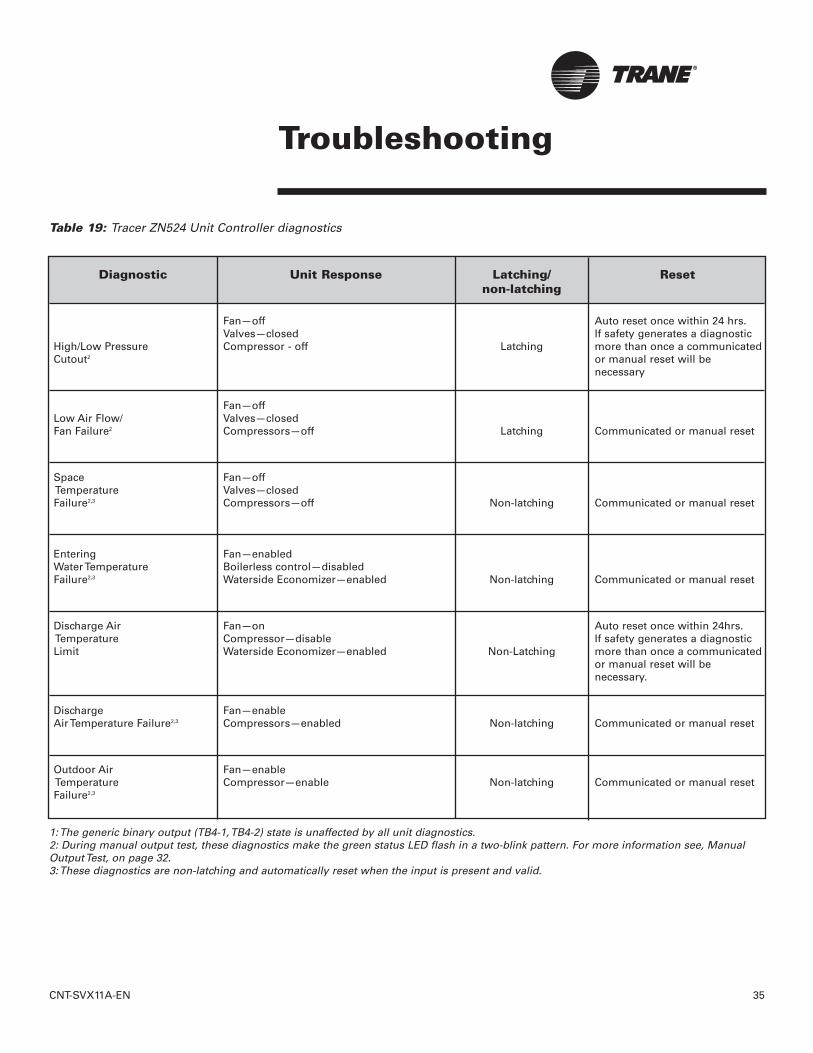
Table 19: Tracer ZN524 Unit Controller diagnostics
1: The generic binary output (TB4-1, TB4-2) state is unaffected by all unit diagnostics.2: During manual output test, these diagnostics make the green status LED flash in a two-blink pattern. For more information see, ManualOutput Test, on page 32.3: These diagnostics are non-latching and automatically reset when the input is present and valid.

36 CNT-SVX11A-EN
Troubleshooting
Diagnostic Unit Response Latching/ Resetnon-latching
Fan—enabledValves—enabled
Humidity Input Failure3 Compressor—enabled Non-latching Communicated or manual resetReheat—disabled
CO2 Sensor Fan—enabledFailure3 Valves—enabled Non-latching Communicated or manual reset
Compressor—enabled
GenericAIP No Unit Reaction Non-latching Communicated or manual resetFailure3
Maintenance Fan—enabledRequired Valves—enabled Non-latching Communicated or manual reset
Compressor—enabled
Local Fan—enabledFan Mode Valves—enabled Non-latching Communicated or manual resetFailure3 Compressor—enabled
Local Fan—enabledSetpoint Valves—enabled Non-latching Communicated or manual resetFailure3 Outdoor air damper—enabled
Invalid Fan—disabledUnit Valves—disabled Latching Communicated or manual resetConfiguration2 Compressor—disabled
Fans—enabledNormal Valves—enabled Non-latching N/A
Compressor—enabled
Table 19: Tracer ZN524 Unit Controller diagnostics - continued
1: The generic binary output (TB4-1, TB4-2) state is unaffected by all unit diagnostics.2: During manual output test, these diagnostics make the green status LED flash in a two-blink pattern. For more information see, ManualOutput Test, on page 32.3: These diagnostics are non-latching and automatically reset when the input is present and valid.
CNT-SVX11A-EN 37
Troubleshooting
Translating MultipleDiagnostics
The controller senses and records eachdiagnostic independently of other diag-nostics. It is possible to have multiplediagnostics present simultaneously. Thediagnostics are reported in the orderthey occur.
Resetting DiagnosticsThere are many ways to reset unit diag-nostics:• Automatically by the controller• By initiating a manual output test at
the controller• By cycling power to the controller• By using a building automation
system• By using the Rover service tool• By cycling the fan switch from off to
ON or AUTO
High/Low Pressure CutoutThe Tracer™ ZN524 Unit Controllerincludes an automatic diagnostic resetfunction. This function attempts to auto-matically recover a unit when theHigh/Low Pressure Cutout diagnosticoccurs. When this diagnostic occurs,the controller responds as defined inTable 19: Tracer™ ZN524 Unit Controllerdiagnostics.
After the controller detects theHigh/Low Pressure Cutout diagnostic,the unit waits 30 minutes before invok-ing the automatic diagnostic reset func-tion. The automatic diagnostic resetfunction clears the High/Low PressureCutout diagnostic and attempts torestore the controller to normal opera-tion. The controller resumes normaloperation until another diagnosticoccurs.
If a High/Low Pressure Cutout diagnos-tic reoccurs within 24 hours after anautomatic diagnostic reset, you mustmanually reset the diagnostic. Seeother possible methods for resettingdiagnostics in this section.
Manual output testThe test button on the controller maybe used either during installation toverify proper end device operation orduring troubleshooting.
When the Test button is pressed, thecontroller exercises all outputs in a pre-defined sequence. The first and laststeps of the sequence reset the con-troller diagnostics. (See “ManualOutput Test” on page 32 for more infor-mation.)
Cycling powerWhen turned-off, the controller's 24VAC power, and power is reapplied, theunit cycles through a power-upsequence and clears all timers. By default, the controller attempts toreset all diagnostics at power-up.
Diagnostics present at power-up andthose that occur after power-up arehandled according to the defined unitdiagnostics sequences (For more infor-mation see,Table 19).
Building automation systemSome building automation systems(i.e., Tracer Summit, Tracker or TracerLoop Controller building automationsystem) can reset diagnostics in theTracer ZN524 unit controller. For morecomplete information, refer to the prod-uct literature for the building automa-tion system.
Rover service toolRover service tool can reset diagnosticsin the Tracer ZN524 unit controller. Formore complete information, refer to theRover Installation, Operation, andProgramming manual.
Diagnostic resetAny device that can communicate thenetwork variable nviRequest (enumera-tion “clear_alarm”) can reset diagnos-tics in the Tracer ZN524 unit controller.The controller also attempts to resetdiagnostics whenever power is cycled.
Cycling the fan switchIf the user cycles the fan speed switchfrom off to ON or AUTO, the controllerresets all diagnostics. Diagnostics mayrecur immediately if the problem stillexists.
38 CNT-SVX11A-EN
Troubleshooting
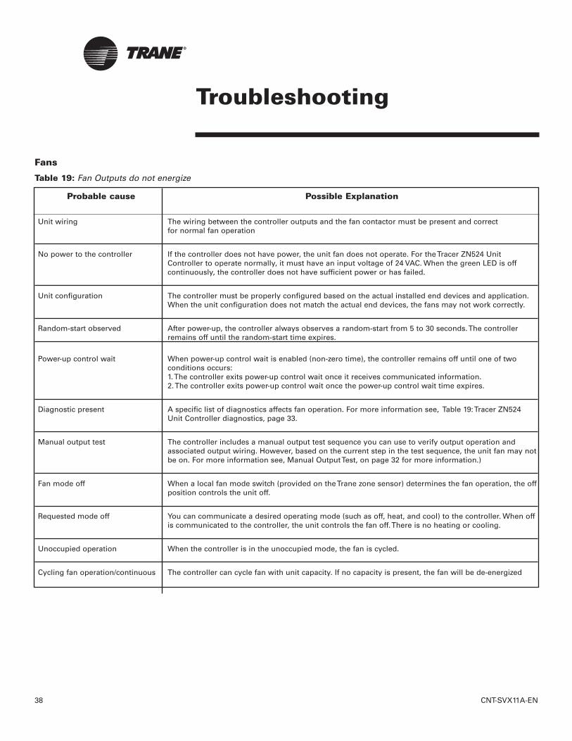
Probable cause Possible Explanation
Unit wiring The wiring between the controller outputs and the fan contactor must be present and correct for normal fan operation
No power to the controller If the controller does not have power, the unit fan does not operate. For the Tracer ZN524 Unit Controller to operate normally, it must have an input voltage of 24 VAC. When the green LED is off continuously, the controller does not have sufficient power or has failed.
Unit configuration The controller must be properly configured based on the actual installed end devices and application. When the unit configuration does not match the actual end devices, the fans may not work correctly.
Random-start observed After power-up, the controller always observes a random-start from 5 to 30 seconds. The controllerremains off until the random-start time expires.
Power-up control wait When power-up control wait is enabled (non-zero time), the controller remains off until one of two conditions occurs:1. The controller exits power-up control wait once it receives communicated information.2. The controller exits power-up control wait once the power-up control wait time expires.
Diagnostic present A specific list of diagnostics affects fan operation. For more information see, Table 19: Tracer ZN524 Unit Controller diagnostics, page 33.
Manual output test The controller includes a manual output test sequence you can use to verify output operation and associated output wiring. However, based on the current step in the test sequence, the unit fan may notbe on. For more information see, Manual Output Test, on page 32 for more information.)
Fan mode off When a local fan mode switch (provided on the Trane zone sensor) determines the fan operation, the offposition controls the unit off.
Requested mode off You can communicate a desired operating mode (such as off, heat, and cool) to the controller. When off is communicated to the controller, the unit controls the fan off. There is no heating or cooling.
Unoccupied operation When the controller is in the unoccupied mode, the fan is cycled.
Cycling fan operation/continuous The controller can cycle fan with unit capacity. If no capacity is present, the fan will be de-energized
Table 19: Fan Outputs do not energize
Fans
CNT-SVX11A-EN 39
Troubleshooting
Probable cause Possible Explanation
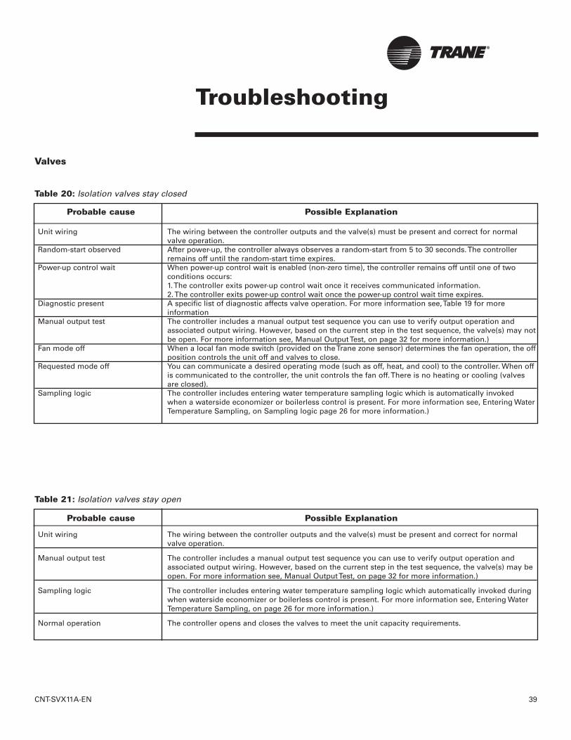
Unit wiring The wiring between the controller outputs and the valve(s) must be present and correct for normal valve operation.
Random-start observed After power-up, the controller always observes a random-start from 5 to 30 seconds. The controller remains off until the random-start time expires.
Power-up control wait When power-up control wait is enabled (non-zero time), the controller remains off until one of twoconditions occurs:1. The controller exits power-up control wait once it receives communicated information.2. The controller exits power-up control wait once the power-up control wait time expires.
Diagnostic present A specific list of diagnostic affects valve operation. For more information see, Table 19 for more information
Manual output test The controller includes a manual output test sequence you can use to verify output operation and associated output wiring. However, based on the current step in the test sequence, the valve(s) may notbe open. For more information see, Manual Output Test, on page 32 for more information.)
Fan mode off When a local fan mode switch (provided on the Trane zone sensor) determines the fan operation, the offposition controls the unit off and valves to close.
Requested mode off You can communicate a desired operating mode (such as off, heat, and cool) to the controller. When off is communicated to the controller, the unit controls the fan off. There is no heating or cooling (valves are closed).
Sampling logic The controller includes entering water temperature sampling logic which is automatically invoked when a waterside economizer or boilerless control is present. For more information see, Entering WaterTemperature Sampling, on Sampling logic page 26 for more information.)
Table 20: Isolation valves stay closed
Probable cause Possible Explanation
Unit wiring The wiring between the controller outputs and the valve(s) must be present and correct for normal valve operation.
Manual output test The controller includes a manual output test sequence you can use to verify output operation and associated output wiring. However, based on the current step in the test sequence, the valve(s) may be open. For more information see, Manual Output Test, on page 32 for more information.)
Sampling logic The controller includes entering water temperature sampling logic which automatically invoked during when waterside economizer or boilerless control is present. For more information see, Entering Water Temperature Sampling, on page 26 for more information.)
Normal operation The controller opens and closes the valves to meet the unit capacity requirements.
Table 21: Isolation valves stay open
Valves

40 CNT-SVX11A-EN
Troubleshooting
Probable cause Possible Explanation
Unit wiring The wiring between the controller outputs and the end devices must be present and correct for normal operation.
Unit configuration The controller must be properly configured based on the actual installed end devices and application. When the unit configuration does not match the actual end devices, the unit may not work correctly.
Diagnostic present A specific list of diagnostics affect compressor and electric heat operation. For more information see, Table 19, page 35 for more information.
Manual output test The controller includes a manual output test sequence you can use to verify output operation and associated output wiring. However, based on the current step in the test sequence, the DX or electric outputs may be off. For more information see, Manual Output Test, on page 32 for more information.)
Normal operation The controller energizes the outputs only as needed to meet the unit capacity requirements.
Table 22: Compressor or electric heat output(s) do not energize
DX/Electric Heat
Probable cause Possible Explanation
Unit wiring The wiring between the controller outputs and the outdoor air damper must be present and correct for normal damper operation.
Unit configuration The controller must be properly configured based on the actual installed end devices and application. When the unit configuration does not match the actual end devices, the damper may not work correctly.
Random-start observed After power-up, the controller always observes a random-start from 5 to 30 seconds. The controller remains off until the random-start time expires.
Power-up control wait When power-up control wait is enabled (non-zero time), the controller remains off until one of twoconditions occurs:1. The controller exits power-up control wait once it receives communicated information.2. The controller exits power-up control wait once the power-up control wait time expires.
Diagnostic present A specific list of diagnostics affects outdoor air operation. For more information see, Table 19 on page 35 for more information.)
Manual output test The controller includes a manual output test sequence you can use to verify output operation and associated output wiring. However, based on the current step in the test sequence, the unit damper may not be open. For more information see, Manual Output Test, on page 32 for more information.)
Fan mode off When a local fan mode switch (provided on the Trane zone sensor) determines the fan operation, the offposition controls the unit off and damper to close.
Table 23: Outside air damper stays closed
Outside Air Damper

CNT-SVX11A-EN 41
Troubleshooting
Probable cause Possible Explanation
Requested mode off You can communicate a desired operating mode (such as off, heat, and cool) to the controller. When off is communicated to the controller, the unit controls the fan off. There is no heating or cooling (valves are closed).
Unoccupied mode When the controller is in the unoccupied mode, the outdoor air damper remains closed.
Warm up and cool-down The controller includes both a morning warm up and cool-down sequence to keep the outdoor air damper closed during the transition from unoccupied to occupied. This is an attempt to bring the space under control as quickly as possible.
The controller opens and closes the outdoor air damper based on the controller's occupancy mode and Normal operation fan operation. Normally, the outdoor air damper is open during occupied, occupied standby, and
occupied bypass mode when the fan is running and closed during unoccupied mode.
Table 23: Outdoor air damper stays closed - continued
Probable cause Possible Explanation
Unit wiring The wiring between the controller outputs and the outdoor air damper must be present and correct for normal damper operation.
Unit configuration The controller must be properly configured based on the actual installed end devices and application. When the unit configuration does not match the actual end devices, the damper may not work correctly.
Manual output test The controller includes a manual output test sequence you can use to verify output operation and associated output wiring. However, based on the current step in the test sequence, the unit damper may be open. For more information see, Manual Output Test, on page 32 for more information.)
The controller opens and closes the outdoor air damper based on the controller's occupancy mode and fan operation. Normally, the outdoor air damper is open during occupied, occupied standby, and
Normal operation occupied bypass mode when the fan is running and closed during unoccupied mode unless the controller is economizing.
Table 24: Outdoor air damper stays open
Probable cause Possible Explanation
Sensor reading too lowUnit economizing without much cooling capacity or unit stops DX heating early and switches to boiler-less electric heat.
Sensor reading too highUnit not utilizing economizer capacity when possible or DX heating stays on longer than possible forboilerless electric heat unit.
Reading out of range Boilerless electric heat or waterside economizer disabled.
Table 25: Entering Water Temperature sensor read-out error

42 CNT-SVX11A-EN
Replacing Circuit Boards
Tracer ZN524 Unit ControllerReplacement
WARNINGHazardous Voltage!
Disconnect all electric power, includingremote disconnects before servicing.Follow proper lockout/tagout proce-dures to ensure the power can not beinadvertently energized. Failure to dis-connect power before servicing couldresult in death or serious injury.
1. Disconnect power or disable the circuit breaker to unit.
2. Remove bad or questionable Tracer ZN524 controller circuit board.
3. Install controller in the unit with the heat-sink placement at the top of the control box.
4. Connect the power to the circuit board ONLY.
5. Connect Rover and properly configure the controller, unless a previously configured board is purchased.
6. Power down.
7. Connect the remaining input and output wiring to the controller and comm wire.
8. Reapply power.
9. Complete sequence 7 and 8 above in the installation section of this manual.
10. Record NID numbers and unit location
11. Refer to BAS manual for instructions on how to configure the new ZN524 into BAS system.
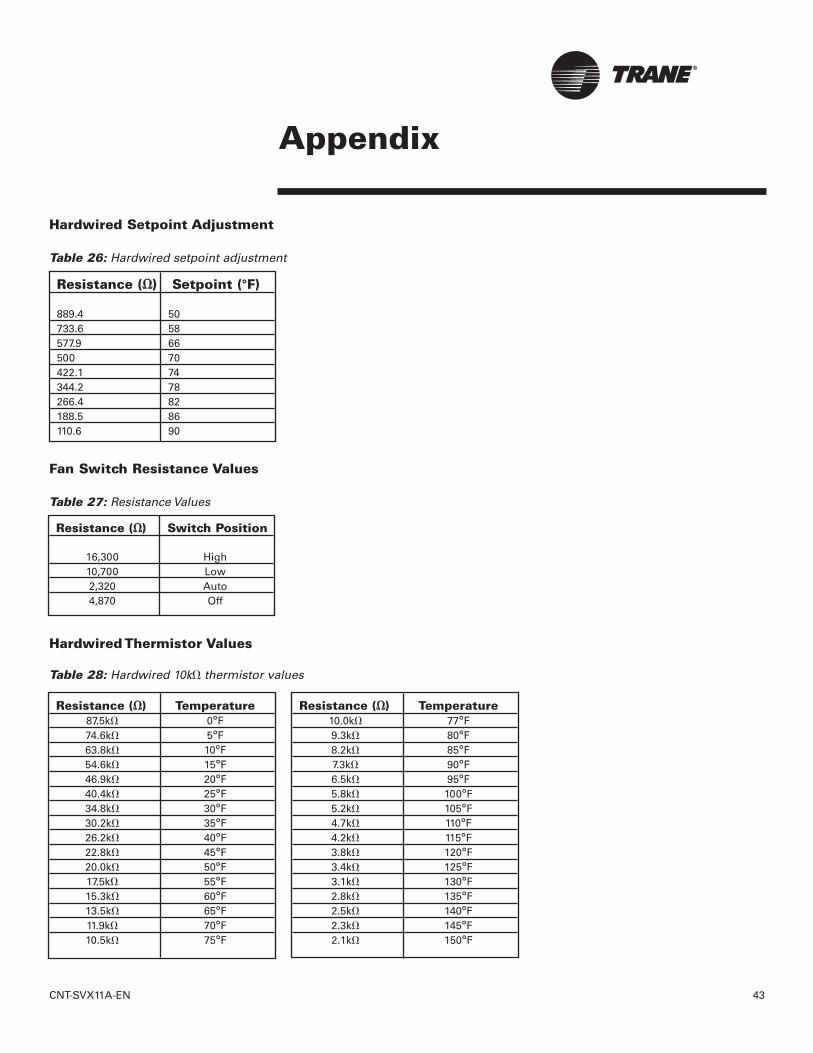
CNT-SVX11A-EN 43
Appendix
Resistance (��) Setpoint (°F)
889.4 50733.6 58577.9 66500 70422.1 74344.2 78266.4 82188.5 86110.6 90
Hardwired Setpoint Adjustment
Table 26: Hardwired setpoint adjustment
Fan Switch Resistance Values
Table 27: Resistance Values
Resistance (��) Switch Position
16,300 High10,700 Low2,320 Auto4,870 Off
Resistance (��) Temperature87.5k� 0°F74.6k� 5°F63.8k� 10°F54.6k� 15°F46.9k� 20°F40.4k� 25°F34.8k� 30°F30.2k� 35°F26.2k� 40°F22.8k� 45°F20.0k� 50°F17.5k� 55°F15.3k� 60°F13.5k� 65°F11.9k� 70°F10.5k� 75°F
Resistance (��) Temperature10.0k� 77°F9.3k� 80°F8.2k� 85°F7.3k� 90°F6.5k� 95°F5.8k� 100°F5.2k� 105°F4.7k� 110°F4.2k� 115°F3.8k� 120°F3.4k� 125°F3.1k� 130°F2.8k� 135°F2.5k� 140°F2.3k� 145°F2.1k� 150°F
Hardwired Thermistor Values
Table 28: Hardwired 10k��thermistor values

44 CNT-SVX11A-EN
Appendix - BinaryConfiguration
Binary input Function Configuration Descriptionor output
BI 1 Low temp detection Normally closed Closed: BIP 1 is Normal (no diagnostic)Open: BIP 1 is Active (diagnostic)
BI 2 Condensate overflow Normally closed Closed: BIP 2 is Normal (no diagnostic)Open: BIP 2 is Active (diagnostic)
BI 3 Occupancy/Generic Normally closed Closed: BIP 3 is Normal (Occupied)Open: BIP 3 is Active (Unoccupied)1
Normally open Open: BIP 3 is Normal (Occupied)Closed: BIP 3 is Active (Unoccupied)1
BI 4 Fan status2 Normally open When the controller commands the fan on and the binary input remains open for one minute, BIP is normal (diagnostic). When the controller commands the fan on and the binary input closes, BIP is active (no diagnostic).
J1-1 Fan Normally open De-energized: Fan offEnergized: Fan on
J1-2 RV Normally open De-energized: HeatEnergized: Cool
J1-3 Electric Heat/ Normally open De-energized: OffReheat Energized: Electric Heat/Reheat active
TB4-1 and TB4-2 Generic binary output Normally open De-energized: Output off (de-energized)Energized: Output on (energized)
1. The occupancy input applications vary for standalone and communicated instances. For more information, see Occupancy arbitrationtables in the Appendix.2. The fan status device is normally closed during normal fan operation. When the fan is off either from a fan failure or the controller com-manding the fan off, the binary input device opens.
Binary Configuration
Table 29: Binary configuration details

CNT-SVX11A-EN 45
Appendix - UnitOperation
Unit Operation Based On The Effective HEAT/COOL Output
Table 30: Unit operation based on HEAT/COOL ouput
Application Heat/cool mode input Effective heat/ cool Unit Operationmode input (nviHeatCool) mode output
(nviApplicMode) (nvoHeatCool)
Auto Determined by controller Fan—EnabledHeating—EnabledCooling—EnabledDamper—Enabled
Heat Heating Fan—EnabledHeating—EnabledCooling—DisabledDamper—Enabled
Morning warm up Pre-heat Fan—EnabledHeating—EnabledCooling—DisabledDamper—Disabled
Cooling Cooling Fan—EnabledHeating—Disabled1
Cooling—EnabledDamper—Enabled
Auto Pre-cool Pre-cool Fan—EnabledHeating—Disabled1
Cooling—EnabledDamper—Disabled
Off Off Fan—DisabledHeating—DisabledCooling—DisabledDamper—Disabled
Test Test Fan—EnabledHeating—EnabledCooling—EnabledDamper—Enabled
Fan only Fan only Fan—EnabledHeating—DisabledCooling—DisabledDamper—Enabled
Not present Determined by controller Fan—EnabledHeating—EnabledCooling—EnabledDamper—Enabled
Heat Any state Heating Fan—EnabledHeating—EnabledCooling—DisabledDamper—Enabled
Morning warm up Any state Pre-heat Fan—EnabledHeating—EnabledCooling—DisabledDamper—Disabled
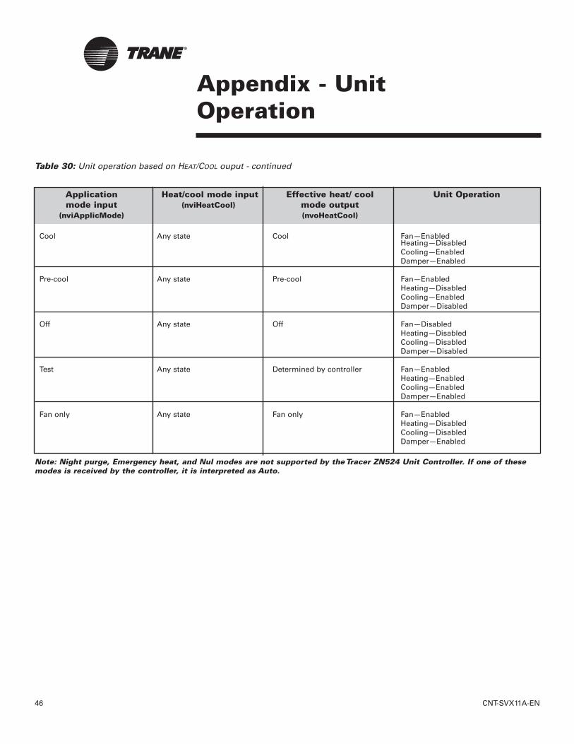
46 CNT-SVX11A-EN
Appendix - UnitOperation
Application Heat/cool mode input Effective heat/ cool Unit Operationmode input (nviHeatCool) mode output
(nviApplicMode) (nvoHeatCool)
Cool Any state Cool Fan—EnabledHeating—DisabledCooling—EnabledDamper—Enabled
Pre-cool Any state Pre-cool Fan—EnabledHeating—DisabledCooling—EnabledDamper—Disabled
Off Any state Off Fan—DisabledHeating—DisabledCooling—DisabledDamper—Disabled
Test Any state Determined by controller Fan—EnabledHeating—EnabledCooling—EnabledDamper—Enabled
Fan only Any state Fan only Fan—EnabledHeating—DisabledCooling—DisabledDamper—Enabled
Note: Night purge, Emergency heat, and Nul modes are not supported by the Tracer ZN524 Unit Controller. If one of thesemodes is received by the controller, it is interpreted as Auto.
Table 30: Unit operation based on HEAT/COOL ouput - continued

CNT-SVX11A-EN 47
Appendix - Data Lists
Table 31: Input/Output listing
Data ListsTable 31 provides an input/output list-ing for the Tracer ZN524 unit controller.The content of the lists conforms toboth the LonMark Space ComfortController Functional Profile and theLonMark node object
Table 32: Configuration properties
Configuration property SNVT type SCPT reference Description
nciSndHrtBt1 SNVT_time_sec SCPTmaxSendTime (49) Send heartbeatnciSetpoints1 SNVT_temp_setpt SCPTsetPnts (60) Occupancy temperature set
pointsnciUnitType1 SNVT_hvac_type SCPThvacUnitType (169) Unit typenciMinOutTm SNVT_time_sec SCPTminSendTime (52) Minimum send timenciRcvHrtBt SNVT_time_sec SCPTmaxRcvTime (48) Receive heartbeatnciLocation SNVT_str_asc SCPTlocation (17) Location labelnciBypassTime SNVT_time_min SCPTbypassTime (34) Local bypass timenciSpaceRHSetpt SNVT_lev_percent SCPThumSetPT(36) Space RH Setpoint
Input SNVT type Output SNVT typenviRequest SNVT_obj_request nvoStatus SNVT_obj_status
nviSpaceTemp1 SNVT_temp_p nvoFileDirectory SNVT_address
nviSetpoint SNVT_temp_p nvoSpaceTemp1 SNVT_temp_p
nviSetptOffset SNVT_temp_p nvoUnitStatus1 SNVT_hvac_status
nviOccSchedule SNVT_tod_event nvoEffectSetpt SNVT_temp_p
nviOccManCmd SNVT_occupancy nvoEffectOccup SNVT_occupancy
nviOccSensor SNVT_occupancy nvoHeatCool SNVT_hvac_mode
nviApplicMode SNVT_hvac_mode nvoSetpoint SNVT_temp_p
nviHeatCool SNVT_hvac_mode nvoDischAirTemp SNVT_temp_p
nviFanSpeedCmd SNVT_switch nvoLoadAbsK SNVT_power_kilo
nviComprEnable SNVT_switch nvoTerminalLoad SNVT_lev_percent
nviAuxHeatEnable SNVT_switch nvoSpaceRH SNVT_lev_percent
nviEconEnable SVNT_switch nvoOutdoorTemp SNVT_temp_p
nviEmergOverride SNVT_hvac_emerg nvoSpaceCO2 SNVT_ppm
nviSourceTemp SNVT_temp_p nvoEnterWaterTemp SNVT_temp_p
nviSpaceRH SNVT_lev_percent nvoLeaveWaterTemp SNVT_temp_p
nviOutdoorTemp SNVT_temp_p
1. Required points under Space Comfort Controller profile. All other points are optional.

48 CNT-SVX11A-EN
Location Identifier

CNT-SVX11A-EN 49
Location Identifier

50 CNT-SVX11A-EN
Location Identifier
CNT-SVX11A-EN 51
Location Identifier

Literature Order Number CNT-SVX11A-EN
Date August 2003
Supercedes New
Stocking Location Inland
Trane has a policy of continuous product and product data improvement andreserves the right to change design and specifications without notice.
Trane A business of American Standard Companieswww.trane.com
For more information, contact your local district office or e-mail us at [email protected]