Installation & Operation Manual - Spartan Controls/media/resources/... · Installation & Operation...
70
www.rosemount.com Reference Manual 00809-0100-4792, Rev CA August 2010 Rosemount 1495 Orifice Plate, 1496 Orifice Flange Union Installation & Operation Manual Rosemount 1495 Orifice Plate Rosemount 1496 Orifice Flange Union
Transcript of Installation & Operation Manual - Spartan Controls/media/resources/... · Installation & Operation...
Reference Manual 00809-0100-4792, Rev CAAugust 2010
Rosemount 1495 Orifice Plate, 1496 Orifice Flange UnionInstallation & Operation Manual
Rosemount 1495Orifice Plate
Rosemount 1496 Orifice Flange Union
www.rosemount.com

Reference Manual 00809-0100-4792, Rev CAAugust 2010 Rosemount 1495, 1496
Rosemount 1495 Orifice PlateRosemount 1496 Orifice Flange UnionInstallation & Operation Manual
NOTICE
Read this manual before working with the product. For personal and system safety, and for optimum product performance, make sure you thoroughly understand the contents before installing, using, or maintaining this product.
Within the United States, Rosemount Inc. has two toll-free assistance numbers.
Customer Central: 1-800-999-9307 (7:00 a.m. to 7:00 p.m. CST)Technical support, quoting, and order-related questions.
North American Response Center: 1-800-654-7768 24 hours a day – Includes Canada Equipment service needs.
For equipment service or support needs outside the United States, contact your local Emerson Process Management representative.
The products described in this document are NOT designed for nuclear qualified applications.
Using non-nuclear qualified products in applications that require nuclear qualified hardware or products may cause inaccurate readings.
For information on Rosemount nuclear-qualified products, contact your local Emerson Process Management Sales Representative.
www.rosemount.com

Reference Manual 00809-0100-4792, Rev CAAugust 2010 Rosemount 1495, 1496
Table of Contents
SECTION 1Introduction
Using This Manual . . . . . . . . . . . . . . . . . . . . . . . . . . . . . . . . . . . . . . . 1-1Service Support . . . . . . . . . . . . . . . . . . . . . . . . . . . . . . . . . . . . . . . . . 1-1Product Recycling/Disposal . . . . . . . . . . . . . . . . . . . . . . . . . . . . . . . . 1-2
SECTION 2Installation, Location, and Orientation
Safety Messages . . . . . . . . . . . . . . . . . . . . . . . . . . . . . . . . . . . . . . . . 2-1Installation Checklist . . . . . . . . . . . . . . . . . . . . . . . . . . . . . . . . . . . . . . 2-1Receiving and Inspection . . . . . . . . . . . . . . . . . . . . . . . . . . . . . . . . . . 2-2Installation Configuration . . . . . . . . . . . . . . . . . . . . . . . . . . . . . . . . . . 2-2Straight Run Requirements. . . . . . . . . . . . . . . . . . . . . . . . . . . . . . . . . 2-3
SECTION 3Hardware Installation for Rosemount 1495 Orifice Plate
1495 Types . . . . . . . . . . . . . . . . . . . . . . . . . . . . . . . . . . . . . . . . . . . . . 3-1Bore Types . . . . . . . . . . . . . . . . . . . . . . . . . . . . . . . . . . . . . . . . . . 3-1
Safety Messages . . . . . . . . . . . . . . . . . . . . . . . . . . . . . . . . . . . . . . . . 3-5Installation Instructions . . . . . . . . . . . . . . . . . . . . . . . . . . . . . . . . . . . . 3-5
Step 1: Determine the Proper Placement . . . . . . . . . . . . . . . . . . . 3-5Step 2: Determine the Proper Orientation . . . . . . . . . . . . . . . . . . . 3-5Step 3: Weld the Flange Union . . . . . . . . . . . . . . . . . . . . . . . . . . . 3-5Step 4: Install the Orifice Plate . . . . . . . . . . . . . . . . . . . . . . . . . . . 3-6
1495 Dimensional Drawings . . . . . . . . . . . . . . . . . . . . . . . . . . . . . . . . 3-81495 Weights (estimated) . . . . . . . . . . . . . . . . . . . . . . . . . . . . . . . . . 3-11
SECTION 4Hardware Installation for Rosemount 1496 Flange Union
1496 Types . . . . . . . . . . . . . . . . . . . . . . . . . . . . . . . . . . . . . . . . . . . . . 4-1Safety Messages . . . . . . . . . . . . . . . . . . . . . . . . . . . . . . . . . . . . . . . . 4-11496 Flange Union Components . . . . . . . . . . . . . . . . . . . . . . . . . . . . 4-2Installation Instructions . . . . . . . . . . . . . . . . . . . . . . . . . . . . . . . . . . . . 4-2
Step 1: Determine the Proper Placement . . . . . . . . . . . . . . . . . . . 4-2Step 2: Determine the Proper Orientation . . . . . . . . . . . . . . . . . . . 4-2Step 3: Weld the Flange Union . . . . . . . . . . . . . . . . . . . . . . . . . . . 4-2Step 4: Install the Orifice Plate . . . . . . . . . . . . . . . . . . . . . . . . . . . 4-3
1496 Dimensional Drawings . . . . . . . . . . . . . . . . . . . . . . . . . . . . . . . . 4-4ASME B16.36-1996 . . . . . . . . . . . . . . . . . . . . . . . . . . . . . . . . . . . . . . 4-51496 Weights (estimated) . . . . . . . . . . . . . . . . . . . . . . . . . . . . . . . . . 4-12
APPENDIX ASpecifications and Reference Data
Specifications . . . . . . . . . . . . . . . . . . . . . . . . . . . . . . . . . . . . . . . . . . . A-1Functional Specifications . . . . . . . . . . . . . . . . . . . . . . . . . . . . . . . . A-1Physical Specifications . . . . . . . . . . . . . . . . . . . . . . . . . . . . . . . . . A-2Return of Materials . . . . . . . . . . . . . . . . . . . . . . . . . . . . . . . . . . . . A-4
Sizing and How to Order. . . . . . . . . . . . . . . . . . . . . . . . . . . . . . . . . . . A-5Rosemount 1495 Configuration . . . . . . . . . . . . . . . . . . . . . . . . . . . . . A-7
Options (Include with selected model number) . . . . . . . . . . . . . . . A-8Rosemount 1496 Configuration . . . . . . . . . . . . . . . . . . . . . . . . . . . . A-10
Ordering Information . . . . . . . . . . . . . . . . . . . . . . . . . . . . . . . . . . A-11Options (Include with selected model number) . . . . . . . . . . . . . . A-12
TOC-1
Reference Manual00809-0100-4792, Rev CA
August 2010Rosemount 1495, 1496
APPENDIX BRecommended Installation Requirements
Recommended Straight Run Requirements . . . . . . . . . . . . . . . . . . . .B-1ISO 5167-2 . . . . . . . . . . . . . . . . . . . . . . . . . . . . . . . . . . . . . . . . . . .B-1AGA Report No. 3. . . . . . . . . . . . . . . . . . . . . . . . . . . . . . . . . . . . . .B-5ASME MFC-3M-2004 . . . . . . . . . . . . . . . . . . . . . . . . . . . . . . . . . . .B-9
Bolt Torque Recommendations . . . . . . . . . . . . . . . . . . . . . . . . . . . . .B-12
APPENDIX CCalculation Data Sheet
TOC-2
Reference Manual 00809-0100-4792, Rev CAAugust 2010 Rosemount 1495, 1496
www.rosemount.com
Section 1 Introduction
Using This Manual . . . . . . . . . . . . . . . . . . . . . . . . . . . . . . .page 1-1Service Support . . . . . . . . . . . . . . . . . . . . . . . . . . . . . . . . .page 1-2Product Recycling/Disposal . . . . . . . . . . . . . . . . . . . . . . .page 1-2
USING THIS MANUAL This product manual provides installation and configuration instructions for the Rosemount 1495 Orifice Plate, Rosemount 1496 Flange Union.
This section contains an explanation of each section of the manual and an installation checklist.
Section 2: Installation, Location, and Orientation explains initial inspection, operating limitations, and in what location and orientation to install the orifice plate and associated hardware.
Section 3: Hardware Installation for Rosemount 1495 Orifice Plate explains how to install the Orifice Plate in either existing orifice flanges or with the Rosemount 1495 Orifice Plate.
Section 4: Hardware Installation for Rosemount 1496 Flange Union explains how to install the 1496 Flange Union.
Appendix A: Specifications and Reference Data supplies reference and specification data, as well as ordering information.
Appendix B: Recommended Installation Requirements shows the recommended straight run requirements and bolt torques used for orifice plate installations.
Appendix C: Calculation Data Sheet
Reference Manual 00809-0100-4792, Rev CAAugust 2010 Rosemount 1495, 1496
www.rosemount.com
SERVICE SUPPORT To expedite the return process outside of the United States, contact the nearest Emerson Process Management representative.
Within the United States, call the Rosemount National Response Center using the 1-800-654-RSMT (7768) toll-free number. This center, available 24 hours a day, will assist you with any needed information or materials.
The center will ask for product model and serial numbers, and will provide a Return Material Authorization (RMA) number. The center will also ask for the process material to which the product was last exposed.
Rosemount National Response Center representatives will explain the additional information and procedures necessary to return goods exposed to hazardous substances.
PRODUCT RECYCLING/DISPOSAL
Recycling of equipment and packaging should be taken into consideration and disposed of in accordance with local and national legislation/regulations.
Individuals who handle products exposed to a hazardous substance can avoid injury if they are informed of and understand the hazard. If the product being returned was exposed to a hazardous substance as defined by OSHA, a copy of the required Material Safety Data Sheet (MSDS) for each hazardous substance identified must be included with the returned goods.
Reference Manual 00809-0100-4792, Rev CAAugust 2010 Rosemount 1495, 1496
Section 2 Installation, Location, and Orientation
Safety Messages . . . . . . . . . . . . . . . . . . . . . . . . . . . . . . . . . page 2-1Installation Checklist . . . . . . . . . . . . . . . . . . . . . . . . . . . . . page 2-1Receiving and Inspection . . . . . . . . . . . . . . . . . . . . . . . . . page 2-2Installation Configuration . . . . . . . . . . . . . . . . . . . . . . . . . page 2-2Straight Run Requirements . . . . . . . . . . . . . . . . . . . . . . . . page 2-3This section describes the orientation, location and alignment limits for installing the Rosemount 1495 Orifice Plate, 1496 Flange Union. Read it thoroughly before starting the installation.
SAFETY MESSAGES Instructions and procedures in this section may require special precautions to ensure the safety of the personnel performing the operations. Please refer to the following safety messages before performing any operation in this section.
INSTALLATION CHECKLIST
The following list is a summary of the steps required to complete a Rosemount 1495 Orifice Plate installation. If this is an entirely new installation, begin with step 1. If the Flange Union is already in place, verify that the orifice flange size and rating match the recommended specifications, and begin with step 5.
1. Determine where the Rosemount 1495 Orifice Plate, 1496 Flange Union is to be placed within the piping system.
2. Establish the proper orientation as determined by the intended service for the orifice plate.
3. Review Appendix B Recommended Installation Requirements.
4. Confirm the Rosemount 1495 and/or 1496 configurations.
5. Measure the pipe’s internal diameter (ID), preferably at 1 x ID from the orifice flange (upstream or downstream), or at the tap location for flange taps.
NOTEProviding the pipe internal diameter at the time of purchase is necessary to maintain published orifice plate accuracy.
6. Install the hardware. Refer to Section 3 for 1495 Orifice Plate installation and Section 4 for 1496 Orifice Flange Union installation.
7. Check for leaks.
8. Commission the orifice plate flowmeter.
Failure to follow these installation guidelines could result in death or serious injury:
* Make sure only qualified personnel perform the installation.
www.rosemount.com
Reference Manual00809-0100-4792, Rev CA
August 2010Rosemount 1495, 1496
2-2
RECEIVING AND INSPECTION
Rosemount 1495 Orifice Plates, 1496 Flange Unions are available in different models and with different options, so it is important to inspect and know which model you have before beginning installation.
Upon receipt of the shipment, check the packing list against the material received and the purchase order. Report any damage to the carrier.
INSTALLATION CONFIGURATION
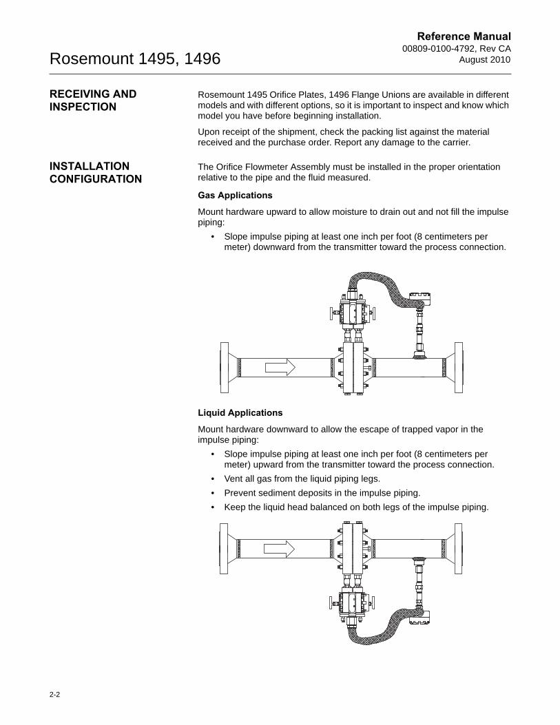
The Orifice Flowmeter Assembly must be installed in the proper orientation relative to the pipe and the fluid measured.
Gas Applications
Mount hardware upward to allow moisture to drain out and not fill the impulse piping:
• Slope impulse piping at least one inch per foot (8 centimeters per meter) downward from the transmitter toward the process connection.
Liquid Applications
Mount hardware downward to allow the escape of trapped vapor in the impulse piping:
• Slope impulse piping at least one inch per foot (8 centimeters per meter) upward from the transmitter toward the process connection.
• Vent all gas from the liquid piping legs.
• Prevent sediment deposits in the impulse piping.
• Keep the liquid head balanced on both legs of the impulse piping.
Reference Manual 00809-0100-4792, Rev CAAugust 2010
2-3
Rosemount 1495, 1496
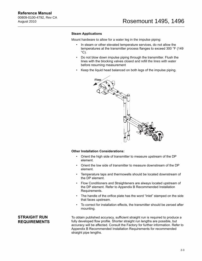
Steam Applications
Mount hardware to allow for a water leg in the impulse piping:
• In steam or other elevated temperature services, do not allow the temperatures at the transmitter process flanges to exceed 300 °F (149 °C).
• Do not blow down impulse piping through the transmitter. Flush the lines with the blocking valves closed and refill the lines with water before resuming measurement
• Keep the liquid head balanced on both legs of the impulse piping.
Other Installation Considerations:• Orient the high side of transmitter to measure upstream of the DP
element.• Orient the low side of transmitter to measure downstream of the DP
element.• Temperature taps and thermowells should be located downstream of
the DP element.• Flow Conditioners and Straighteners are always located upstream of
the DP element. Refer to Appendix B Recommended Installation Requirements.
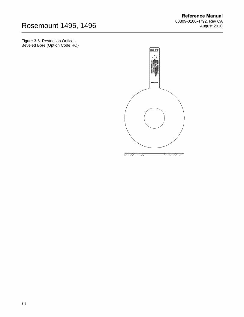
• The handle of the orifice plate has the word “Inlet” stamped on the side that faces upstream.
• To correct for installation effects, the transmitter should be zeroed after mounting.
STRAIGHT RUN REQUIREMENTS
To obtain published accuracy, sufficient straight run is required to produce a fully developed flow profile. Shorter straight run lengths are possible, but accuracy will be affected. Consult the Factory for further information. Refer to Appendix B Recommended Installation Requirements for recommended straight pipe lengths.
Flow

Reference Manual00809-0100-4792, Rev CA
August 2010Rosemount 1495, 1496
2-4
Reference Manual 00809-0100-4792, Rev CAAugust 2010 Rosemount 1495, 1496
Section 3 Hardware Installation for Rosemount 1495 Orifice Plate
1495 Types . . . . . . . . . . . . . . . . . . . . . . . . . . . . . . . . . . . . . . page 3-1Safety Messages . . . . . . . . . . . . . . . . . . . . . . . . . . . . . . . . . page 3-5Installation Instructions . . . . . . . . . . . . . . . . . . . . . . . . . . . page 3-51495 Dimensional Drawings . . . . . . . . . . . . . . . . . . . . . . . page 3-81495 Weights (estimated) . . . . . . . . . . . . . . . . . . . . . . . . . . page 3-11
1495 TYPES This section provides hardware installation instructions for the Rosemount 1495 Orifice Plate. Installation procedures are similar for all services. Service-specific instructions are provided where necessary. Otherwise, all instructions in this section apply to all services. For more information on 1495 Orifice Plate types, see page A-6.
• Refer to transmitter installation instructions where applicable.
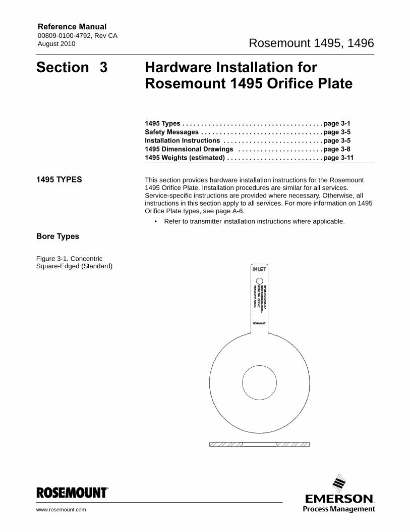
Bore Types
Figure 3-1. Concentric Square-Edged (Standard)
www.rosemount.com
Reference Manual00809-0100-4792, Rev CA
August 2010Rosemount 1495, 1496
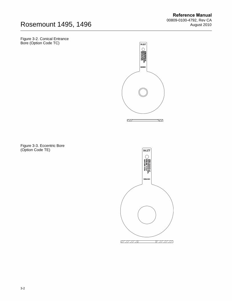
Figure 3-2. Conical Entrance Bore (Option Code TC)
Figure 3-3. Eccentric Bore (Option Code TE)
3-2
Reference Manual 00809-0100-4792, Rev CAAugust 2010 Rosemount 1495, 1496
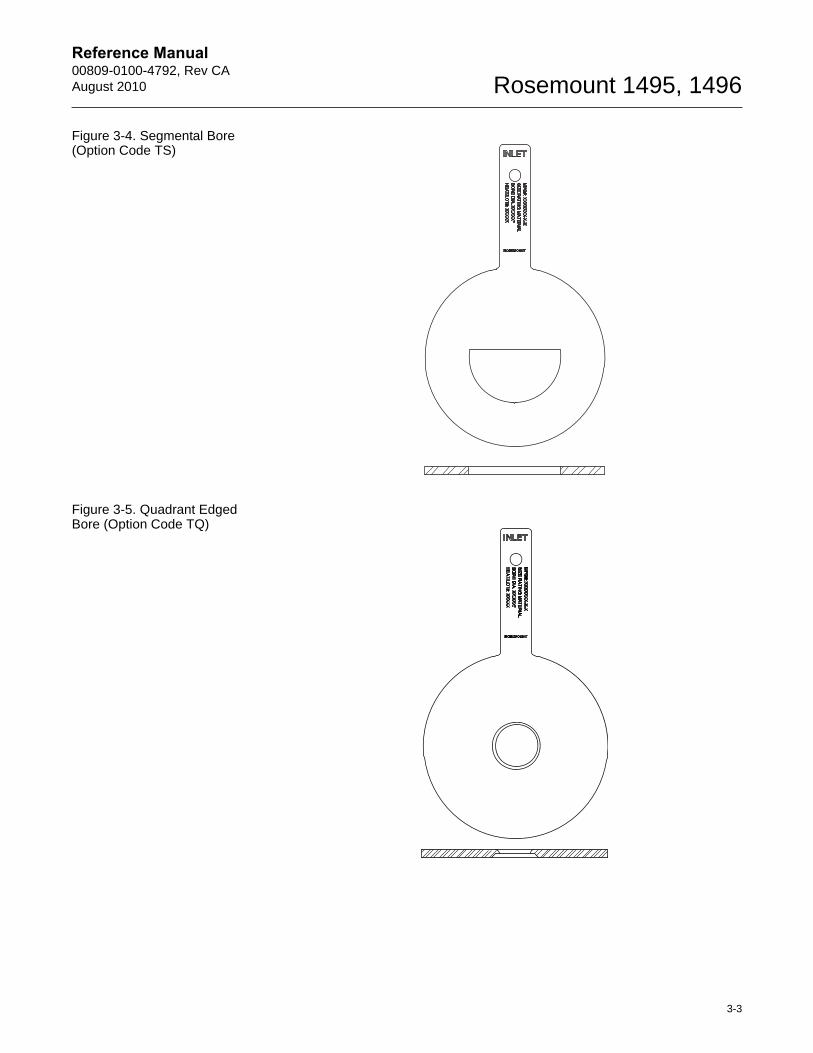
Figure 3-4. Segmental Bore (Option Code TS)
Figure 3-5. Quadrant Edged Bore (Option Code TQ)
3-3
Reference Manual00809-0100-4792, Rev CA
August 2010Rosemount 1495, 1496
Figure 3-6. Restriction Orifice - Beveled Bore (Option Code RO)
3-4

Reference Manual 00809-0100-4792, Rev CAAugust 2010 Rosemount 1495, 1496
SAFETY MESSAGES Instructions and procedures in this section may require special precautions to ensure the safety of the personnel performing the operations. Please refer to the following safety messages before performing any operation in this section.
INSTALLATION INSTRUCTIONS
Step 1: Determine the Proper Placement
Determine the proper placement by ensuring adequate straight run. See Appendix B: Recommended Installation Requirements.
Step 2: Determine the Proper Orientation
To determine the proper orientation, see “Installation Configuration” on page 2-2.
Step 3: Weld the Flange Union
To weld the flange union, see “Step 3: Weld the Flange Union” on page 4-2.
Failure to follow these installation guidelines could result in death or serious injury:
* Make sure only qualified personnel perform the installation.
Personal hazard! To prevent injury, remove pressure and drain pipe assembly before installing or removing orifice plate.
If the process fluid is caustic or otherwise hazardous, the procedure outlined here must be modified as required to prevent death or serious injury to personnel.
3-5
Reference Manual00809-0100-4792, Rev CA
August 2010Rosemount 1495, 1496
Step 4: Install the Orifice Plate
General installation instructions to install (or remove) the orifice plate are as follows:
1. Make certain the pipeline is not under pressure and has been drained or purged.
2. Loosen all studs and nuts.
3. Remove the studs in one half of the flange union.
4. Spread flange union by turning jackscrews clockwise.
5. Install new plate or remove existing plate for replacement or inspection.
6. Install new gaskets when installing plate. It is recommended to install new gaskets each time orifice flange union is separated.
7. Release the flange union by turning Jackscrews counter clockwise.
8. Replace studs.
9. Tighten studs in a star pattern. See “Bolt Torque Recommendations” on page B-12.
NOTERefer to published standards (AGA3, ASME MFC-3M, ISO 5167 for installation guidelines.
Once the orifice plate is installed, proceed by installing connection systems, manifolds, and/or transmitters per manufacturer’s recommended specifications and plant standards.
NOTEUniversal style orifice plates are designed for installation into junior or senior orifice fittings as well as into RTJ Plate Holders.
3-6
Reference Manual 00809-0100-4792, Rev CAAugust 2010 Rosemount 1495, 1496
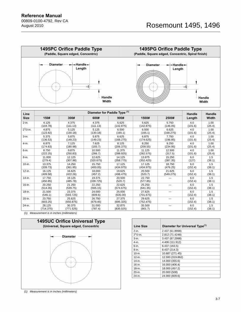
1495PC Orifice Paddle Type (Paddle, Square edged, Concentric)
1495PG Orifice Paddle Type (Paddle, Square edged, Concentric, Spiral finish)
Line Size
Diameter for Paddle Type (1)Handle Length
Handle Width 150# 300# 600# 900# 1500# 2500#
2-in. 4.125(104.78)
4.375 (111.13)
4.375 (111.13)
5.625 (142.875)
5.625 (142.875)
5.750 (146.05)
4.0(101.6)
1.00 (25.4)
21/2-in. 4.875 (123.82)
5.125(130.18)
5.125 (130.18)
6.500 (165.1)
6.500 (165.1)
6.625 (168.275)
4.0(101.6)
1.00 (25.4)
3-in. 5.375 (136.53)
5.875 (149.23)
5.875 (149.23)
6.625 (168.275)
6.875 (174.625)
7.750 (196.85)
4.0(101.6)
1.00 (25.4)
4-in. 6.875 (174.63)
7.125 (180.98)
7.625 (193.7)
8.125 (206.375)
8.250 (209.55)
9.250 (234.95)
4.0 (101.6)
1.00 (25.4)
6-in. 8.750 (222.25)
9.875 (250.83)
10.500 (266.7)
11.375 (288.925)
11.125 (282.575)
12.500 (317.5)
4.0 (101.6)
1.00 (25.4)
8-in. 11.000 (279.4)
12.125(307.98)
12.625 (320.675)
14.125 (358.775)
13.875 (352.425)
15.250 (387.35)
6.0 (127)
1.5(38.1)
10-in. 13.375 (339.73)
14.250 (361.95)
15.750 (400.05)
17.125 (434.975)
17.125 (434.975)
18.750 (476.25)
6.0(152.4)
1.5(38.1)
12-in. 16.125 (409.58)
16.625 (422.26)
18.000 (457.2)
19.625 (498.475)
20.500 (520.7)
21.625 (549.275)
6.0(152.4)
1.5(38.1)
14-in. 17.750 (450.85)
19.125 (485.78)
19.375 (339.725)
20.500 (520.7)
22.750 (577.85)
— 6.0 (152.4)
1.5(38.1)
16-in. 20.250 (514.35)
21.250 (539.75)
22.250 (565.15)
22.625 (574.675)
25.250 (641.35)
— 6.0(152.4)
1.5(38.1)
18-in. 21.500 (546.1)
23.375 (593.725)
24.000 (609.6)
25.000 (635.00)
27.625 (701.675)
— 6.0(152.4)
1.5(38.1)
20-in. 23.750 (603.25)
25.625 (650.875)
26.750 (679.45)
27.375 (695.325)
29.625 (752.475)
— 6.0(152.4)
1.5(38.1)
24-in. 28.125 (714.375)
30.375 (771.525)
31.000 (787.4)
32.875 (835.025)
35.500 (901.7)
— 6.0(152.4)
1.5(38.1)
(1) Measurement is in inches (millimeters)
1495UC Orifice Universal Type (Universal, Square edged, Concentric Line Size Diameter for Universal Type(1)
2-in. 2.437 (61.8998)21/2-in. 2.812 (71.4248)3-in. 3.437 (87.2998)4-in. 4.406 (111.912)6-in. 6.437 (163.5)8-in. 8.437 (214.3)10-in. 10.687 (271.45)12-in. 12.593 (319.862)14-in. 14.000 (355.6)16-in. 16.000 (406.4)18-in. 18.000 (457.2)20-in. 20.000 (508)24-in. 24.000 (609.6)
(1) Measurement is in inches (millimeters)
Diameter Handle Length
Handle Width
Diameter Handle Length
Handle Width
Diameter
3-7
Reference Manual00809-0100-4792, Rev CA
August 2010Rosemount 1495, 1496
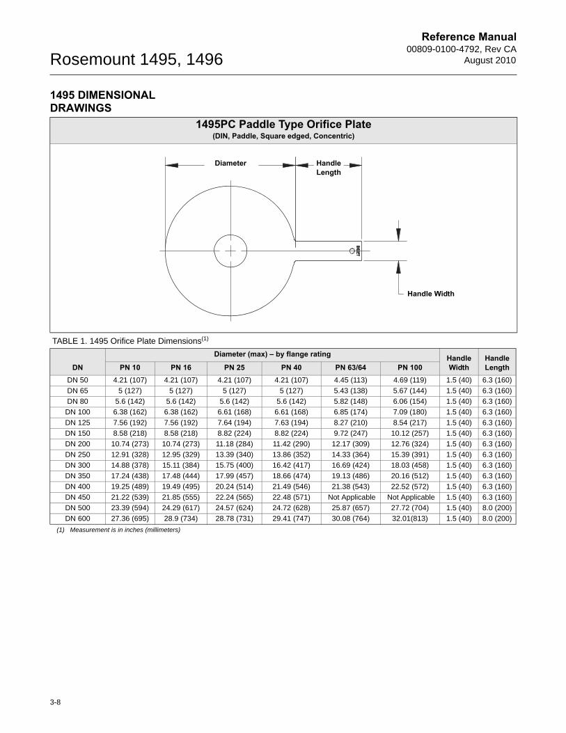
1495 DIMENSIONAL DRAWINGS
1495PC Paddle Type Orifice Plate (DIN, Paddle, Square edged, Concentric)
TABLE 1. 1495 Orifice Plate Dimensions(1)
DN
Diameter (max) – by flange rating HandleWidth
HandleLengthPN 10 PN 16 PN 25 PN 40 PN 63/64 PN 100
DN 50 4.21 (107) 4.21 (107) 4.21 (107) 4.21 (107) 4.45 (113) 4.69 (119) 1.5 (40) 6.3 (160)
DN 65 5 (127) 5 (127) 5 (127) 5 (127) 5.43 (138) 5.67 (144) 1.5 (40) 6.3 (160)
DN 80 5.6 (142) 5.6 (142) 5.6 (142) 5.6 (142) 5.82 (148) 6.06 (154) 1.5 (40) 6.3 (160)
DN 100 6.38 (162) 6.38 (162) 6.61 (168) 6.61 (168) 6.85 (174) 7.09 (180) 1.5 (40) 6.3 (160)
DN 125 7.56 (192) 7.56 (192) 7.64 (194) 7.63 (194) 8.27 (210) 8.54 (217) 1.5 (40) 6.3 (160)
DN 150 8.58 (218) 8.58 (218) 8.82 (224) 8.82 (224) 9.72 (247) 10.12 (257) 1.5 (40) 6.3 (160)
DN 200 10.74 (273) 10.74 (273) 11.18 (284) 11.42 (290) 12.17 (309) 12.76 (324) 1.5 (40) 6.3 (160)
DN 250 12.91 (328) 12.95 (329) 13.39 (340) 13.86 (352) 14.33 (364) 15.39 (391) 1.5 (40) 6.3 (160)
DN 300 14.88 (378) 15.11 (384) 15.75 (400) 16.42 (417) 16.69 (424) 18.03 (458) 1.5 (40) 6.3 (160)
DN 350 17.24 (438) 17.48 (444) 17.99 (457) 18.66 (474) 19.13 (486) 20.16 (512) 1.5 (40) 6.3 (160)
DN 400 19.25 (489) 19.49 (495) 20.24 (514) 21.49 (546) 21.38 (543) 22.52 (572) 1.5 (40) 6.3 (160)
DN 450 21.22 (539) 21.85 (555) 22.24 (565) 22.48 (571) Not Applicable Not Applicable 1.5 (40) 6.3 (160)
DN 500 23.39 (594) 24.29 (617) 24.57 (624) 24.72 (628) 25.87 (657) 27.72 (704) 1.5 (40) 8.0 (200)
DN 600 27.36 (695) 28.9 (734) 28.78 (731) 29.41 (747) 30.08 (764) 32.01(813) 1.5 (40) 8.0 (200)
(1) Measurement is in inches (millimeters)
Handle Width
Diameter Handle Length
3-8
Reference Manual 00809-0100-4792, Rev CAAugust 2010 Rosemount 1495, 1496
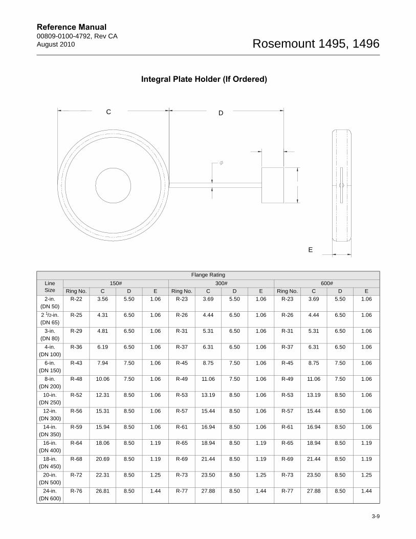
Integral Plate Holder (If Ordered)
Flange Rating
Line Size
150# 300# 600#
Ring No. C D E Ring No. C D E Ring No. C D E
2-in. (DN 50)
R-22 3.56 5.50 1.06 R-23 3.69 5.50 1.06 R-23 3.69 5.50 1.06
2 1/2-in. (DN 65)
R-25 4.31 6.50 1.06 R-26 4.44 6.50 1.06 R-26 4.44 6.50 1.06
3-in. (DN 80)
R-29 4.81 6.50 1.06 R-31 5.31 6.50 1.06 R-31 5.31 6.50 1.06
4-in. (DN 100)
R-36 6.19 6.50 1.06 R-37 6.31 6.50 1.06 R-37 6.31 6.50 1.06
6-in. (DN 150)
R-43 7.94 7.50 1.06 R-45 8.75 7.50 1.06 R-45 8.75 7.50 1.06
8-in. (DN 200)
R-48 10.06 7.50 1.06 R-49 11.06 7.50 1.06 R-49 11.06 7.50 1.06
10-in. (DN 250)
R-52 12.31 8.50 1.06 R-53 13.19 8.50 1.06 R-53 13.19 8.50 1.06
12-in. (DN 300)
R-56 15.31 8.50 1.06 R-57 15.44 8.50 1.06 R-57 15.44 8.50 1.06
14-in. (DN 350)
R-59 15.94 8.50 1.06 R-61 16.94 8.50 1.06 R-61 16.94 8.50 1.06
16-in. (DN 400)
R-64 18.06 8.50 1.19 R-65 18.94 8.50 1.19 R-65 18.94 8.50 1.19
18-in. (DN 450)
R-68 20.69 8.50 1.19 R-69 21.44 8.50 1.19 R-69 21.44 8.50 1.19
20-in. (DN 500)
R-72 22.31 8.50 1.25 R-73 23.50 8.50 1.25 R-73 23.50 8.50 1.25
24-in. (DN 600)
R-76 26.81 8.50 1.44 R-77 27.88 8.50 1.44 R-77 27.88 8.50 1.44
C D
E
3-9
Reference Manual00809-0100-4792, Rev CA
August 2010Rosemount 1495, 1496
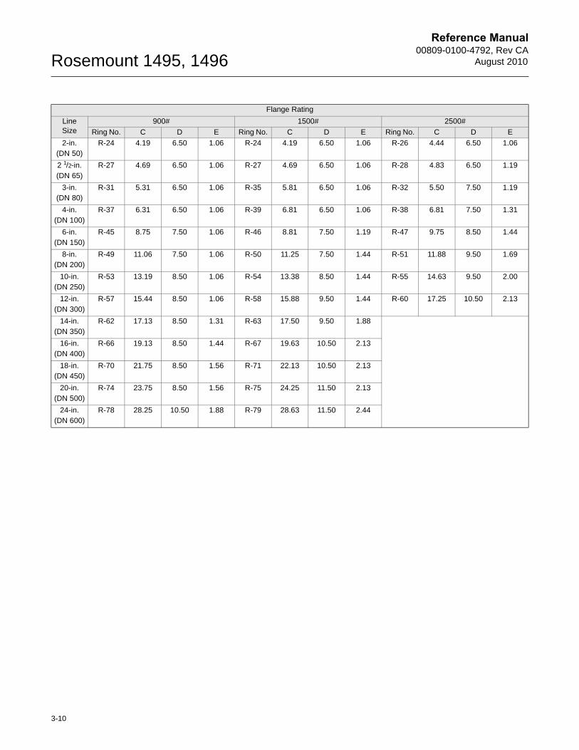
Flange Rating
Line Size
900# 1500# 2500#
Ring No. C D E Ring No. C D E Ring No. C D E
2-in. (DN 50)
R-24 4.19 6.50 1.06 R-24 4.19 6.50 1.06 R-26 4.44 6.50 1.06
2 1/2-in. (DN 65)
R-27 4.69 6.50 1.06 R-27 4.69 6.50 1.06 R-28 4.83 6.50 1.19
3-in. (DN 80)
R-31 5.31 6.50 1.06 R-35 5.81 6.50 1.06 R-32 5.50 7.50 1.19
4-in. (DN 100)
R-37 6.31 6.50 1.06 R-39 6.81 6.50 1.06 R-38 6.81 7.50 1.31
6-in. (DN 150)
R-45 8.75 7.50 1.06 R-46 8.81 7.50 1.19 R-47 9.75 8.50 1.44
8-in. (DN 200)
R-49 11.06 7.50 1.06 R-50 11.25 7.50 1.44 R-51 11.88 9.50 1.69
10-in. (DN 250)
R-53 13.19 8.50 1.06 R-54 13.38 8.50 1.44 R-55 14.63 9.50 2.00
12-in. (DN 300)
R-57 15.44 8.50 1.06 R-58 15.88 9.50 1.44 R-60 17.25 10.50 2.13
14-in. (DN 350)
R-62 17.13 8.50 1.31 R-63 17.50 9.50 1.88
16-in. (DN 400)
R-66 19.13 8.50 1.44 R-67 19.63 10.50 2.13
18-in. (DN 450)
R-70 21.75 8.50 1.56 R-71 22.13 10.50 2.13
20-in. (DN 500)
R-74 23.75 8.50 1.56 R-75 24.25 11.50 2.13
24-in. (DN 600)
R-78 28.25 10.50 1.88 R-79 28.63 11.50 2.44
3-10
Reference Manual 00809-0100-4792, Rev CAAugust 2010 Rosemount 1495, 1496
)
)
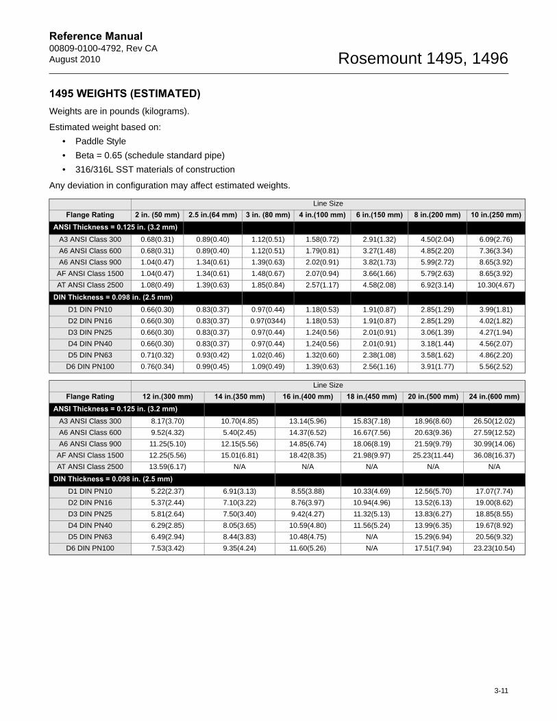
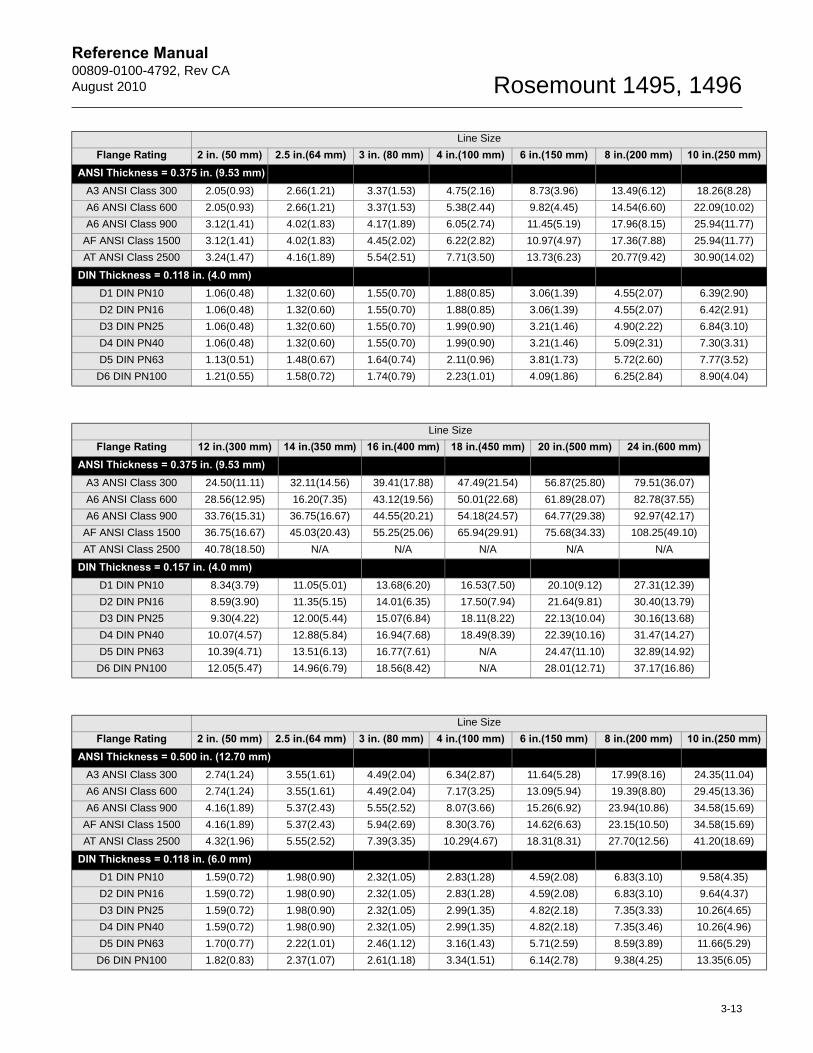
1495 WEIGHTS (ESTIMATED)Weights are in pounds (kilograms).
Estimated weight based on:
• Paddle Style
• Beta = 0.65 (schedule standard pipe)
• 316/316L SST materials of construction
Any deviation in configuration may affect estimated weights.
Line Size
Flange Rating 2 in. (50 mm) 2.5 in.(64 mm) 3 in. (80 mm) 4 in.(100 mm) 6 in.(150 mm) 8 in.(200 mm) 10 in.(250 mmANSI Thickness = 0.125 in. (3.2 mm)
A3 ANSI Class 300 0.68(0.31) 0.89(0.40) 1.12(0.51) 1.58(0.72) 2.91(1.32) 4.50(2.04) 6.09(2.76)
A6 ANSI Class 600 0.68(0.31) 0.89(0.40) 1.12(0.51) 1.79(0.81) 3.27(1.48) 4.85(2.20) 7.36(3.34)
A6 ANSI Class 900 1.04(0.47) 1.34(0.61) 1.39(0.63) 2.02(0.91) 3.82(1.73) 5.99(2.72) 8.65(3.92)
AF ANSI Class 1500 1.04(0.47) 1.34(0.61) 1.48(0.67) 2.07(0.94) 3.66(1.66) 5.79(2.63) 8.65(3.92)
AT ANSI Class 2500 1.08(0.49) 1.39(0.63) 1.85(0.84) 2.57(1.17) 4.58(2.08) 6.92(3.14) 10.30(4.67)
DIN Thickness = 0.098 in. (2.5 mm)D1 DIN PN10 0.66(0.30) 0.83(0.37) 0.97(0.44) 1.18(0.53) 1.91(0.87) 2.85(1.29) 3.99(1.81)
D2 DIN PN16 0.66(0.30) 0.83(0.37) 0.97(0344) 1.18(0.53) 1.91(0.87) 2.85(1.29) 4.02(1.82)
D3 DIN PN25 0.66(0.30) 0.83(0.37) 0.97(0.44) 1.24(0.56) 2.01(0.91) 3.06(1.39) 4.27(1.94)
D4 DIN PN40 0.66(0.30) 0.83(0.37) 0.97(0.44) 1.24(0.56) 2.01(0.91) 3.18(1.44) 4.56(2.07)
D5 DIN PN63 0.71(0.32) 0.93(0.42) 1.02(0.46) 1.32(0.60) 2.38(1.08) 3.58(1.62) 4.86(2.20)
D6 DIN PN100 0.76(0.34) 0.99(0.45) 1.09(0.49) 1.39(0.63) 2.56(1.16) 3.91(1.77) 5.56(2.52)
Line Size
Flange Rating 12 in.(300 mm) 14 in.(350 mm) 16 in.(400 mm) 18 in.(450 mm) 20 in.(500 mm) 24 in.(600 mmANSI Thickness = 0.125 in. (3.2 mm)
A3 ANSI Class 300 8.17(3.70) 10.70(4.85) 13.14(5.96) 15.83(7.18) 18.96(8.60) 26.50(12.02)
A6 ANSI Class 600 9.52(4.32) 5.40(2.45) 14.37(6.52) 16.67(7.56) 20.63(9.36) 27.59(12.52)
A6 ANSI Class 900 11.25(5.10) 12.15(5.56) 14.85(6.74) 18.06(8.19) 21.59(9.79) 30.99(14.06)
AF ANSI Class 1500 12.25(5.56) 15.01(6.81) 18.42(8.35) 21.98(9.97) 25.23(11.44) 36.08(16.37)
AT ANSI Class 2500 13.59(6.17) N/A N/A N/A N/A N/A
DIN Thickness = 0.098 in. (2.5 mm)D1 DIN PN10 5.22(2.37) 6.91(3.13) 8.55(3.88) 10.33(4.69) 12.56(5.70) 17.07(7.74)
D2 DIN PN16 5.37(2.44) 7.10(3.22) 8.76(3.97) 10.94(4.96) 13.52(6.13) 19.00(8.62)
D3 DIN PN25 5.81(2.64) 7.50(3.40) 9.42(4.27) 11.32(5.13) 13.83(6.27) 18.85(8.55)
D4 DIN PN40 6.29(2.85) 8.05(3.65) 10.59(4.80) 11.56(5.24) 13.99(6.35) 19.67(8.92)
D5 DIN PN63 6.49(2.94) 8.44(3.83) 10.48(4.75) N/A 15.29(6.94) 20.56(9.32)
D6 DIN PN100 7.53(3.42) 9.35(4.24) 11.60(5.26) N/A 17.51(7.94) 23.23(10.54)
3-11
Reference Manual 00809-0100-4792, Rev CAAugust 2010 Rosemount 1495, 1496
)
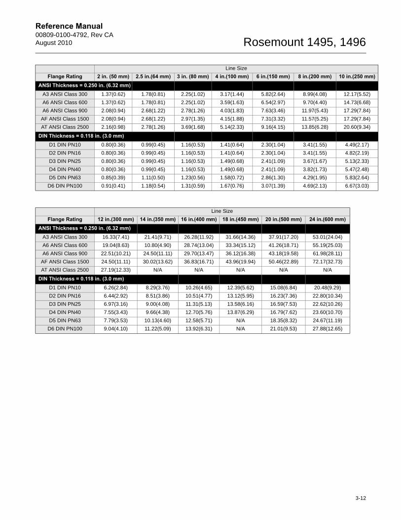
Line SizeFlange Rating 2 in. (50 mm) 2.5 in.(64 mm) 3 in. (80 mm) 4 in.(100 mm) 6 in.(150 mm) 8 in.(200 mm) 10 in.(250 mmANSI Thickness = 0.250 in. (6.32 mm)
A3 ANSI Class 300 1.37(0.62) 1.78(0.81) 2.25(1.02) 3.17(1.44) 5.82(2.64) 8.99(4.08) 12.17(5.52)
A6 ANSI Class 600 1.37(0.62) 1.78(0.81) 2.25(1.02) 3.59(1.63) 6.54(2.97) 9.70(4.40) 14.73(6.68)
A6 ANSI Class 900 2.08(0.94) 2.68(1.22) 2.78(1.26) 4.03(1.83) 7.63(3.46) 11.97(5.43) 17.29(7.84)
AF ANSI Class 1500 2.08(0.94) 2.68(1.22) 2.97(1.35) 4.15(1.88) 7.31(3.32) 11.57(5.25) 17.29(7.84)
AT ANSI Class 2500 2.16(0.98) 2.78(1.26) 3.69(1.68) 5.14(2.33) 9.16(4.15) 13.85(6.28) 20.60(9.34)
DIN Thickness = 0.118 in. (3.0 mm)D1 DIN PN10 0.80(0.36) 0.99(0.45) 1.16(0.53) 1.41(0.64) 2.30(1.04) 3.41(1.55) 4.49(2.17)
D2 DIN PN16 0.80(0.36) 0.99(0.45) 1.16(0.53) 1.41(0.64) 2.30(1.04) 3.41(1.55) 4.82(2.19)
D3 DIN PN25 0.80(0.36) 0.99(0.45) 1.16(0.53) 1.49(0.68) 2.41(1.09) 3.67(1.67) 5.13(2.33)
D4 DIN PN40 0.80(0.36) 0.99(0.45) 1.16(0.53) 1.49(0.68) 2.41(1.09) 3.82(1.73) 5.47(2.48)
D5 DIN PN63 0.85(0.39) 1.11(0.50) 1.23(0.56) 1.58(0.72) 2.86(1.30) 4.29(1.95) 5.83(2.64)
D6 DIN PN100 0.91(0.41) 1.18(0.54) 1.31(0.59) 1.67(0.76) 3.07(1.39) 4.69(2.13) 6.67(3.03)
Line Size
Flange Rating 12 in.(300 mm) 14 in.(350 mm) 16 in.(400 mm) 18 in.(450 mm) 20 in.(500 mm) 24 in.(600 mm)ANSI Thickness = 0.250 in. (6.32 mm)
A3 ANSI Class 300 16.33(7.41) 21.41(9.71) 26.28(11.92) 31.66(14.36) 37.91(17.20) 53.01(24.04)
A6 ANSI Class 600 19.04(8.63) 10.80(4.90) 28.74(13.04) 33.34(15.12) 41.26(18.71) 55.19(25.03)
A6 ANSI Class 900 22.51(10.21) 24.50(11.11) 29.70(13.47) 36.12(16.38) 43.18(19.58) 61.98(28.11)
AF ANSI Class 1500 24.50(11.11) 30.02(13.62) 36.83(16.71) 43.96(19.94) 50.46(22.89) 72.17(32.73)
AT ANSI Class 2500 27.19(12.33) N/A N/A N/A N/A N/A
DIN Thickness = 0.118 in. (3.0 mm)D1 DIN PN10 6.26(2.84) 8.29(3.76) 10.26(4.65) 12.39(5.62) 15.08(6.84) 20.48(9.29)
D2 DIN PN16 6.44(2.92) 8.51(3.86) 10.51(4.77) 13.12(5.95) 16.23(7.36) 22.80(10.34)
D3 DIN PN25 6.97(3.16) 9.00(4.08) 11.31(5.13) 13.58(6.16) 16.59(7.53) 22.62(10.26)
D4 DIN PN40 7.55(3.43) 9.66(4.38) 12.70(5.76) 13.87(6.29) 16.79(7.62) 23.60(10.70)
D5 DIN PN63 7.79(3.53) 10.13(4.60) 12.58(5.71) N/A 18.35(8.32) 24.67(11.19)
D6 DIN PN100 9.04(4.10) 11.22(5.09) 13.92(6.31) N/A 21.01(9.53) 27.88(12.65)
3-12
Reference Manual 00809-0100-4792, Rev CAAugust 2010 Rosemount 1495, 1496
)
)
Line Size
Flange Rating 2 in. (50 mm) 2.5 in.(64 mm) 3 in. (80 mm) 4 in.(100 mm) 6 in.(150 mm) 8 in.(200 mm) 10 in.(250 mmANSI Thickness = 0.375 in. (9.53 mm)
A3 ANSI Class 300 2.05(0.93) 2.66(1.21) 3.37(1.53) 4.75(2.16) 8.73(3.96) 13.49(6.12) 18.26(8.28)
A6 ANSI Class 600 2.05(0.93) 2.66(1.21) 3.37(1.53) 5.38(2.44) 9.82(4.45) 14.54(6.60) 22.09(10.02)
A6 ANSI Class 900 3.12(1.41) 4.02(1.83) 4.17(1.89) 6.05(2.74) 11.45(5.19) 17.96(8.15) 25.94(11.77)
AF ANSI Class 1500 3.12(1.41) 4.02(1.83) 4.45(2.02) 6.22(2.82) 10.97(4.97) 17.36(7.88) 25.94(11.77)
AT ANSI Class 2500 3.24(1.47) 4.16(1.89) 5.54(2.51) 7.71(3.50) 13.73(6.23) 20.77(9.42) 30.90(14.02)
DIN Thickness = 0.118 in. (4.0 mm)D1 DIN PN10 1.06(0.48) 1.32(0.60) 1.55(0.70) 1.88(0.85) 3.06(1.39) 4.55(2.07) 6.39(2.90)
D2 DIN PN16 1.06(0.48) 1.32(0.60) 1.55(0.70) 1.88(0.85) 3.06(1.39) 4.55(2.07) 6.42(2.91)
D3 DIN PN25 1.06(0.48) 1.32(0.60) 1.55(0.70) 1.99(0.90) 3.21(1.46) 4.90(2.22) 6.84(3.10)
D4 DIN PN40 1.06(0.48) 1.32(0.60) 1.55(0.70) 1.99(0.90) 3.21(1.46) 5.09(2.31) 7.30(3.31)
D5 DIN PN63 1.13(0.51) 1.48(0.67) 1.64(0.74) 2.11(0.96) 3.81(1.73) 5.72(2.60) 7.77(3.52)
D6 DIN PN100 1.21(0.55) 1.58(0.72) 1.74(0.79) 2.23(1.01) 4.09(1.86) 6.25(2.84) 8.90(4.04)
Line Size
Flange Rating 12 in.(300 mm) 14 in.(350 mm) 16 in.(400 mm) 18 in.(450 mm) 20 in.(500 mm) 24 in.(600 mm)ANSI Thickness = 0.375 in. (9.53 mm)
A3 ANSI Class 300 24.50(11.11) 32.11(14.56) 39.41(17.88) 47.49(21.54) 56.87(25.80) 79.51(36.07)
A6 ANSI Class 600 28.56(12.95) 16.20(7.35) 43.12(19.56) 50.01(22.68) 61.89(28.07) 82.78(37.55)
A6 ANSI Class 900 33.76(15.31) 36.75(16.67) 44.55(20.21) 54.18(24.57) 64.77(29.38) 92.97(42.17)
AF ANSI Class 1500 36.75(16.67) 45.03(20.43) 55.25(25.06) 65.94(29.91) 75.68(34.33) 108.25(49.10)
AT ANSI Class 2500 40.78(18.50) N/A N/A N/A N/A N/A
DIN Thickness = 0.157 in. (4.0 mm)D1 DIN PN10 8.34(3.79) 11.05(5.01) 13.68(6.20) 16.53(7.50) 20.10(9.12) 27.31(12.39)
D2 DIN PN16 8.59(3.90) 11.35(5.15) 14.01(6.35) 17.50(7.94) 21.64(9.81) 30.40(13.79)
D3 DIN PN25 9.30(4.22) 12.00(5.44) 15.07(6.84) 18.11(8.22) 22.13(10.04) 30.16(13.68)
D4 DIN PN40 10.07(4.57) 12.88(5.84) 16.94(7.68) 18.49(8.39) 22.39(10.16) 31.47(14.27)
D5 DIN PN63 10.39(4.71) 13.51(6.13) 16.77(7.61) N/A 24.47(11.10) 32.89(14.92)
D6 DIN PN100 12.05(5.47) 14.96(6.79) 18.56(8.42) N/A 28.01(12.71) 37.17(16.86)
Line Size
Flange Rating 2 in. (50 mm) 2.5 in.(64 mm) 3 in. (80 mm) 4 in.(100 mm) 6 in.(150 mm) 8 in.(200 mm) 10 in.(250 mmANSI Thickness = 0.500 in. (12.70 mm)
A3 ANSI Class 300 2.74(1.24) 3.55(1.61) 4.49(2.04) 6.34(2.87) 11.64(5.28) 17.99(8.16) 24.35(11.04)
A6 ANSI Class 600 2.74(1.24) 3.55(1.61) 4.49(2.04) 7.17(3.25) 13.09(5.94) 19.39(8.80) 29.45(13.36)
A6 ANSI Class 900 4.16(1.89) 5.37(2.43) 5.55(2.52) 8.07(3.66) 15.26(6.92) 23.94(10.86) 34.58(15.69)
AF ANSI Class 1500 4.16(1.89) 5.37(2.43) 5.94(2.69) 8.30(3.76) 14.62(6.63) 23.15(10.50) 34.58(15.69)
AT ANSI Class 2500 4.32(1.96) 5.55(2.52) 7.39(3.35) 10.29(4.67) 18.31(8.31) 27.70(12.56) 41.20(18.69)
DIN Thickness = 0.118 in. (6.0 mm)D1 DIN PN10 1.59(0.72) 1.98(0.90) 2.32(1.05) 2.83(1.28) 4.59(2.08) 6.83(3.10) 9.58(4.35)
D2 DIN PN16 1.59(0.72) 1.98(0.90) 2.32(1.05) 2.83(1.28) 4.59(2.08) 6.83(3.10) 9.64(4.37)
D3 DIN PN25 1.59(0.72) 1.98(0.90) 2.32(1.05) 2.99(1.35) 4.82(2.18) 7.35(3.33) 10.26(4.65)
D4 DIN PN40 1.59(0.72) 1.98(0.90) 2.32(1.05) 2.99(1.35) 4.82(2.18) 7.35(3.46) 10.26(4.96)
D5 DIN PN63 1.70(0.77) 2.22(1.01) 2.46(1.12) 3.16(1.43) 5.71(2.59) 8.59(3.89) 11.66(5.29)
D6 DIN PN100 1.82(0.83) 2.37(1.07) 2.61(1.18) 3.34(1.51) 6.14(2.78) 9.38(4.25) 13.35(6.05)
3-13

Reference Manual 00809-0100-4792, Rev CAAugust 2010 Rosemount 1495, 1496
Line Size
Flange Rating 12 in.(300 mm) 14 in.(350 mm) 16 in.(400 mm) 18 in.(450 mm) 20 in.(500 mm) 24 in.(600 mm)ANSI Thickness = 0.500 in. (12.70 mm)
A3 ANSI Class 300 32.67(14.82) 42.81(19.42) 52.55(23.84) 63.31(28.72) 75.83(34.39) 106.02(48.09)
A6 ANSI Class 600 38.07(17.27) 21.60(9.80) 57.19(26.08) 66.67(30.24) 82.51(37.43) 110.37(50.06)
A6 ANSI Class 900 45.01(20.42) 49.00(22.22) 59.40(26.94) 72.24(32.77) 86.35(39.17) 123.96(56.23)
AF ANSI Class 1500 49.00(22.22) 60.04(27.23) 73.66(33.41) 87.91(39.88) 100.91(45.77) 144.34(65.47)
AT ANSI Class 2500 54.38(24.66) N/A N/A N/A N/A N/A
DIN Thickness = 0.118 in. (6.0 mm)D1 DIN PN10 12.52(5.68) 16.58(7.52) 20.51(9.31) 24.79(11.24) 30.15(13.68) 40.96(18.58)
D2 DIN PN16 12.89(5.85) 17.03(7.72) 21.01(9.53) 26.24(11.90) 32.46(14.72) 45.60(20.69)
D3 DIN PN25 13.95(6.33) 18300(8.16) 22.61(10.26) 27.17(12.32) 33.19(15.05) 45.23(20.52)
D4 DIN PN40 15.10(6.85) 19.32(8.76) 25.41(11.52) 27.74(12.58) 33.59(15.23) 47.20(21.41)
D5 DIN PN63 15.58(7.07) 20.27(9.19) 25.16(11.41) N/A 36.71(16.65) 49.34(22.38)
D6 DIN PN100 18.08(8.20) 22.44(10.18) 27.84(12.63) N/A 42.02(19.06) 55.76(25.29)
3-14
Reference Manual 00809-0100-4792, Rev CAAugust 2010 Rosemount 1495, 1496
Section 4 Hardware Installation for Rosemount 1496 Flange Union
1496 Types . . . . . . . . . . . . . . . . . . . . . . . . . . . . . . . . . . . . . . page 4-1Safety Messages . . . . . . . . . . . . . . . . . . . . . . . . . . . . . . . . . page 4-11496 Flange Union Components . . . . . . . . . . . . . . . . . . . . page 4-2Installation Instructions . . . . . . . . . . . . . . . . . . . . . . . . . . . page 4-21496 Dimensional Drawings . . . . . . . . . . . . . . . . . . . . . . . page 4-41496 Weights (estimated) . . . . . . . . . . . . . . . . . . . . . . . . . . page 4-12
1496 TYPES This section provides hardware installation instructions for the Rosemount 1496 Flange Union. Installation procedures are similar for all services. Service-specific instructions are provided where necessary. Otherwise, all instructions in this section apply to all services. For more information on 1496 Flange Unions, see page A-6.
• Refer to transmitter installation instructions where applicable.
SAFETY MESSAGES Instructions and procedures in this section may require special precautions to ensure the safety of the personnel performing the operations. Please refer to the following safety messages before performing any operation in this section.
Failure to follow these installation guidelines could result in death or serious injury:
* Make sure only qualified personnel perform the installation.
www.rosemount.com
Reference Manual00809-0100-4792, Rev CA
August 2010Rosemount 1495, 1496
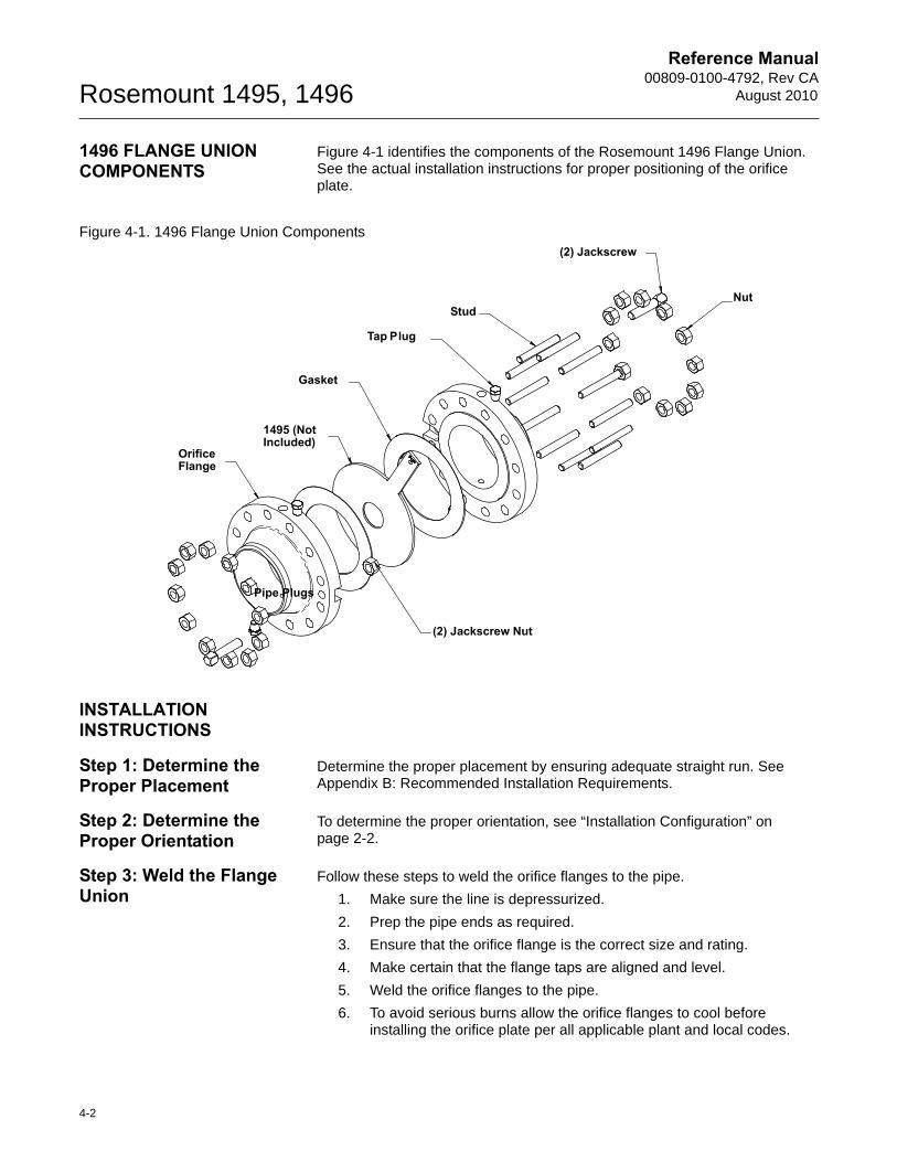
1496 FLANGE UNION COMPONENTS
Figure 4-1 identifies the components of the Rosemount 1496 Flange Union. See the actual installation instructions for proper positioning of the orifice plate.
Figure 4-1. 1496 Flange Union Components
INSTALLATION INSTRUCTIONS
Step 1: Determine the Proper Placement
Determine the proper placement by ensuring adequate straight run. See Appendix B: Recommended Installation Requirements.
Step 2: Determine the Proper Orientation
To determine the proper orientation, see “Installation Configuration” on page 2-2.
Step 3: Weld the Flange Union
Follow these steps to weld the orifice flanges to the pipe.
1. Make sure the line is depressurized.
2. Prep the pipe ends as required.
3. Ensure that the orifice flange is the correct size and rating.
4. Make certain that the flange taps are aligned and level.
5. Weld the orifice flanges to the pipe.
6. To avoid serious burns allow the orifice flanges to cool before installing the orifice plate per all applicable plant and local codes.
1495 (Not Included)
Pipe Plugs
Nut
Tap Plug
Orifice Flange
(2) Jackscrew
Stud
Gasket
(2) Jackscrew Nut
4-2
Reference Manual 00809-0100-4792, Rev CAAugust 2010 Rosemount 1495, 1496
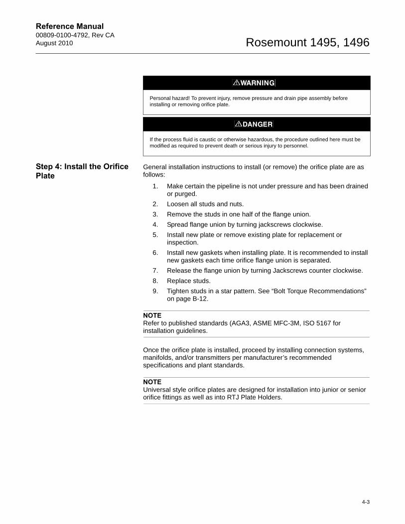
Step 4: Install the Orifice Plate
General installation instructions to install (or remove) the orifice plate are as follows:
1. Make certain the pipeline is not under pressure and has been drained or purged.
2. Loosen all studs and nuts.
3. Remove the studs in one half of the flange union.
4. Spread flange union by turning jackscrews clockwise.
5. Install new plate or remove existing plate for replacement or inspection.
6. Install new gaskets when installing plate. It is recommended to install new gaskets each time orifice flange union is separated.
7. Release the flange union by turning Jackscrews counter clockwise.
8. Replace studs.
9. Tighten studs in a star pattern. See “Bolt Torque Recommendations” on page B-12.
NOTERefer to published standards (AGA3, ASME MFC-3M, ISO 5167 for installation guidelines.
Once the orifice plate is installed, proceed by installing connection systems, manifolds, and/or transmitters per manufacturer’s recommended specifications and plant standards.
NOTEUniversal style orifice plates are designed for installation into junior or senior orifice fittings as well as into RTJ Plate Holders.
Personal hazard! To prevent injury, remove pressure and drain pipe assembly before installing or removing orifice plate.
If the process fluid is caustic or otherwise hazardous, the procedure outlined here must be modified as required to prevent death or serious injury to personnel.
4-3

Reference Manual00809-0100-4792, Rev CA
August 2010Rosemount 1495, 1496
1496 DIMENSIONAL DRAWINGS
Figure 4-2. Class 300X
A
B1
1
R
O
Weld Neck
Y1
C
0.06 0.94
1/2 NPT (1)
X
QB
R G
O
Threaded
Y2 F
QF
C
0.06 0.94
1/2 NPT (1)
1
X
B2
Slip-On
Y2C
0.060.94
1/2 NPT (1)
1
4-4
Reference Manual 00809-0100-4792, Rev CAAugust 2010 Rosemount 1495, 1496
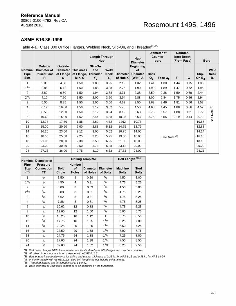
ASME B16.36-1996Table 4-1. Class 300 Orifice Flanges, Welding Neck, Slip-On, and Threaded(1)(2)
Nominal Pipe Size
Outside Diameter of Raised Face
R
Outside Diameter of Flange
O
Thickness of Flange,
Min. C
Length Through Hub
Diameter of Hub X
Hub Diameter
Beginning of
Chamfer (W.N.) A
Diameter of Counter-
bore
Counter-bore Depth (From Face) Bore
Slip-On and
Threaded Y2
Weld Neck
Y1
Back QB Face QF F G
Slip-On B2
WeldNeck
B1
1 2.00 4.88 1.50 1.88 3.25 2.12 1.32 1.41 1.30 1.44 0.75 1.36
11/2 2.88 6.12 1.50 1.88 3.38 2.75 1.90 1.99 1.89 1.47 0.72 1.95
2 3.62 6.50 1.50 1.94 3.38 3.31 2.38 2.50 2.36 1.50 0.69 2.44
21/2 4.12 7.50 1.50 2.00 3.50 3.94 2.88 3.00 2.84 1.75 0.56 2.94
3 5.00 8.25 1.50 2.06 3.50 4.62 3.50 3.63 3.46 1.81 0.56 3.57
4 6.19 10.00 1.50 2.12 3.62 5.75 4.50 4.63 4.45 1.88 0.56 4.57
6 8.50 12.50 1.50 2.12 3.94 8.12 6.63 6.75 6.57 1.88 0.31 6.72
8 10.62 15.00 1.62 2.44 4.38 10.25 8.63 8.75 8.55 2.19 0.44 8.72
10 12.75 17.50 1.88 2.62 4.62 1262 10.75
See Note (6).
10.88
12 15.00 20.50 2.00 2.88 5.12 14.75 12.75 12.88
14 16.25 23.00 2.12 3.00 5.62 16.75 14.00 14.14
16 18.50 25.50 2.25 3.25 5.75 19.00 16.00 16.16
18 21.00 28.00 2.38 3.50 6.25 21.00 18.00 18.18
20 23.00 30.50 2.50 3.75 6.38 23.12 20.00 20.20
24 27.25 36.00 2.75 4.19 6.62 27.62 24.00 24.25
Nominal Pipe Size(1)(2)
Diameter of Pressure
Connection TT
Drilling Template Bolt Length (3)(4)
Bolt Circle
Numberof
HolesDiameter of Holes
Diameter of Bolts
Machine Bolts
Stud Bolts
1 1/4 3.50 4 0.69 5/8 4.50 5.00 (5)
11/2 1/4 4.50 4 0.81 3/4 4.75 5.25
2 1/4 5.00 8 0.69 5/8 4.50 5.00 (6)
21/2 1/4 5.88 8 0.81 3/4 4.75 5.25
3 3/8 6.62 8 0.81 3/4 4.75 5.25
4 1/2 7.88 8 0.81 3/4 4.75 5.25
6 1/2 10.62 12 0.88 3/4 4.75 5.25
8 1/2 13.00 12 1.00 7/8 5.00 5.75
10 1/2 15.25 16 1.12 1 5.75 6.50
12 1/2 17.75 16 1.25 11/8 6.25 7.00
14 1/2 20.25 20 1.25 11/8 6.50 7.25
16 1/2 22.50 20 1.38 11/4 7.00 7.75
18 1/2 24.75 24 1.38 11/4 7.25 8.00
20 1/2 27.00 24 1.38 11/4 7.50 8.50
24 1/2 32.00 24 1.62 11/2 8.25 9.50
(1) Weld neck flanges NPS 3 and smaller are identical to Class 600 flanges and may be so marked.(2) All other dimensions are in accordance with ASME B16.5.(3) Bolt lengths include allowance for orifice and gasket thickness of 0.25 in. for NPS 1-12 and 0.38 in. for NPS 14-24. (4) In conformance with ASME B16.5, stud bolt lengths do not include point heights. (5) Threaded flanges are furnished in NPS 1-8 only.(6) Bore diameter of weld neck flanges is to be specified by the purchaser.
See
Not
e (5
)
4-5

Reference Manual00809-0100-4792, Rev CA
August 2010Rosemount 1495, 1496
Figure 4-3. Class 600
Table 4-2. Class 600 Orifice Flanges, Welding Neck(1)(2)
Nominal Pipe Size
Outside Diameter of Raised
Face R
Outside Diameter of Flange
O
Thickness of Flange,
Min. C
Length Through
Hub Y
Height of Raised Face H
Ring Type Joint
Diameter of Hub X
Hub Diameter
Beginning of
Chamfer AGroove Number
Pitch Diameter
PGroove Depth E
Groove Width F
Radius at
Bottom rmax
Special Oval Ring
Height W
1 2.00 4.88 1.44 3.19 0.06 R16 2.000 0.250 0.344 0.03 1.00 2.12 1.32
11/2 2.88 6.12 1.44 3.32 0.06 R20 2.688 0.250 0.344 0.03 1.00 2.75 1.90
2 3.62 6.50 1.44 3.32 0.06 R23 3.250 0.312 0.469 0.03 1.06 3.31 2.38
21/2 4.12 7.50 1.44 3.44 0.06 R26 4.000 0.312 0.469 0.03 1.06 3.94 2.88
3 5.00 8.25 1.44 3.44 0.06 R31 4.875 0.312 0.469 0.03 1.06 4.62 3.50
4 6.19 10.75 1.50 4.00 0.25 R37 5.875 0.312 0.469 0.03 1.06 6.00 4.50
6 8.50 14.00 1.88 4.62 0.25 R45 8.312 0.312 0.469 0.03 1.06 8.75 6.63
8 10.62 16.50 2.19 5.25 0.25 R49 10.625 0.312 0.469 0.03 1.06 10.75 8.63
10 12.75 20.00 2.50 6.00 0.25 R53 12.750 0.312 0.469 0.03 1.06 13.50 10.75
12 15.00 22.00 2.62 6.12 0.25 R57 15.000 0.312 0.469 0.03 1.06 15.75 12.75
14 16.25 23.75 2.75 6.50 0.25 R61 16.500 0.312 0.469 0.03 1.06 17.00 14.00
16 18.50 27.00 3.00 7.00 0.25 R65 18.500 0.312 0.469 0.03 1.19 19.50 16.00
18 21.00 29.25 3.25 7.25 0.25 R69 21.000 0.312 0.469 0.03 1.19 21.50 18.00
20 23.00 32.00 3.50 7.50 0.25 R73 23.000 0.375 0.531 0.06 1.25 24.00 20.00
24 27.25 37.00 4.00 8.00 0.25 R77 27.250 0.438 0.656 0.06 1.44 28.25 24.00
X
A
B
1
R
O
Raised Face
Y
C
0.25 0.94
1/2 NPT (1)
1
P
Ring Type Joint
Y
CE 0.75
Special One or Two Piece Ring and Orifice Plate Assembly
W
Groove Detail
E
F
23 deg.
r
4-6
Reference Manual 00809-0100-4792, Rev CAAugust 2010 Rosemount 1495, 1496
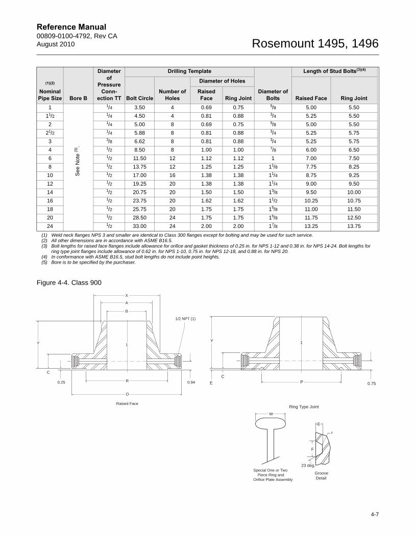
Figure 4-4. Class 900
(1)(2)
Nominal Pipe Size Bore B
Diameter of
Pressure Conn-
ection TT
Drilling Template
Diameter of Bolts
Length of Stud Bolts(3)(4) (5)
Bolt CircleNumber of
Holes
Diameter of Holes
Raised Face Ring JointRaised Face Ring Joint
1 1/4 3.50 4 0.69 0.75 5/8 5.00 5.50
11/2 1/4 4.50 4 0.81 0.88 3/4 5.25 5.50
2 1/4 5.00 8 0.69 0.75 5/8 5.00 5.50
21/2 1/4 5.88 8 0.81 0.88 3/4 5.25 5.75
3 3/8 6.62 8 0.81 0.88 3/4 5.25 5.75
4 1/2 8.50 8 1.00 1.00 7/8 6.00 6.50
6 1/2 11.50 12 1.12 1.12 1 7.00 7.50
8 1/2 13.75 12 1.25 1.25 11/8 7.75 8.25
10 1/2 17.00 16 1.38 1.38 11/4 8.75 9.25
12 1/2 19.25 20 1.38 1.38 11/4 9.00 9.50
14 1/2 20.75 20 1.50 1.50 13/8 9.50 10.00
16 1/2 23.75 20 1.62 1.62 11/2 10.25 10.75
18 1/2 25.75 20 1.75 1.75 15/8 11.00 11.50
20 1/2 28.50 24 1.75 1.75 15/8 11.75 12.50
24 1/2 33.00 24 2.00 2.00 17/8 13.25 13.75
(1) Weld neck flanges NPS 3 and smaller are identical to Class 300 flanges except for bolting and may be used for such service.(2) All other dimensions are in accordance with ASME B16.5.(3) Bolt lengths for raised face flanges include allowance for orifice and gasket thickness of 0.25 in. for NPS 1-12 and 0.38 in. for NPS 14-24. Bolt lengths for
ring type joint flanges include allowance of 0.62 in. for NPS 1-10, 0.75 in. for NPS 12-18, and 0.88 in. for NPS 20.(4) In conformance with ASME B16.5, stud bolt lengths do not include point heights.(5) Bore is to be specified by the purchaser.
See
Not
e (5
) .
X
A
B
1
R
O
Raised Face
Y
C
0.25 0.94
1/2 NPT (1)
1
P
Ring Type Joint
Y
CE 0.75
Special One or Two Piece Ring and Orifice Plate Assembly
W
Groove Detail
E
F
23 deg.
r
4-7
Reference Manual00809-0100-4792, Rev CA
August 2010Rosemount 1495, 1496
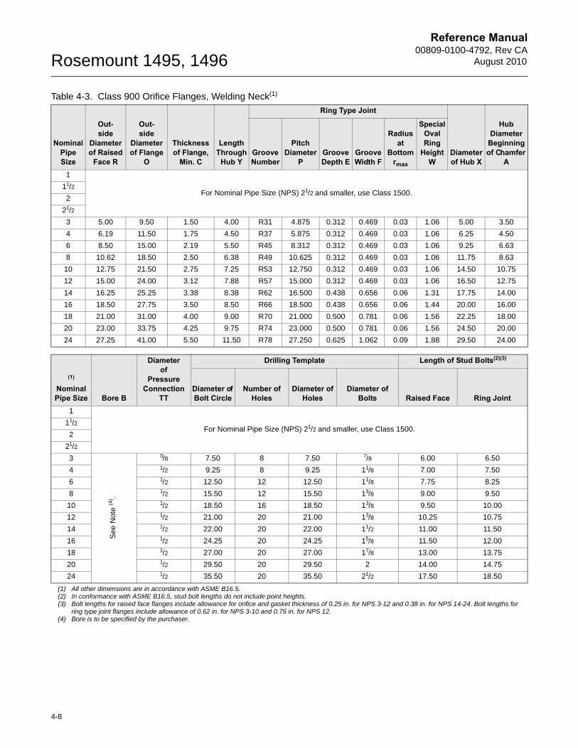
Table 4-3. Class 900 Orifice Flanges, Welding Neck(1)
Nominal Pipe Size
Out-side
Diameter of Raised
Face R
Out-side
Diameter of Flange
O
Thickness of Flange,
Min. C
Length Through
Hub Y
Ring Type Joint
Diameter of Hub X
Hub Diameter
Beginning of Chamfer
AGroove Number
Pitch Diameter
PGroove Depth E
Groove Width F
Radius at
Bottom rmax
Special Oval Ring
Height W
1
For Nominal Pipe Size (NPS) 21/2 and smaller, use Class 1500.11/2
2
21/2
3 5.00 9.50 1.50 4.00 R31 4.875 0.312 0.469 0.03 1.06 5.00 3.50
4 6.19 11.50 1.75 4.50 R37 5.875 0.312 0.469 0.03 1.06 6.25 4.50
6 8.50 15.00 2.19 5.50 R45 8.312 0.312 0.469 0.03 1.06 9.25 6.63
8 10.62 18.50 2.50 6.38 R49 10.625 0.312 0.469 0.03 1.06 11.75 8.63
10 12.75 21.50 2.75 7.25 R53 12.750 0.312 0.469 0.03 1.06 14.50 10.75
12 15.00 24.00 3.12 7.88 R57 15.000 0.312 0.469 0.03 1.06 16.50 12.75
14 16.25 25.25 3.38 8.38 R62 16.500 0.438 0.656 0.06 1.31 17.75 14.00
16 18.50 27.75 3.50 8.50 R66 18.500 0.438 0.656 0.06 1.44 20.00 16.00
18 21.00 31.00 4.00 9.00 R70 21.000 0.500 0.781 0.06 1.56 22.25 18.00
20 23.00 33.75 4.25 9.75 R74 23.000 0.500 0.781 0.06 1.56 24.50 20.00
24 27.25 41.00 5.50 11.50 R78 27.250 0.625 1.062 0.09 1.88 29.50 24.00
(1)
Nominal Pipe Size Bore B
Diameter of
Pressure Connection
TT
Drilling Template Length of Stud Bolts(2)(3) (4)
Diameter of Bolt Circle
Number of Holes
Diameter of Holes
Diameter of Bolts Raised Face Ring Joint
1
For Nominal Pipe Size (NPS) 21/2 and smaller, use Class 1500.11/2
2
21/2
3 3/8 7.50 8 7.50 7/8 6.00 6.50
4 1/2 9.25 8 9.25 11/8 7.00 7.50
6 1/2 12.50 12 12.50 11/8 7.75 8.25
8 1/2 15.50 12 15.50 13/8 9.00 9.50
10 1/2 18.50 16 18.50 13/8 9.50 10.00
12 1/2 21.00 20 21.00 13/8 10.25 10.75
14 1/2 22.00 20 22.00 11/2 11.00 11.50
16 1/2 24.25 20 24.25 15/8 11.50 12.00
18 1/2 27.00 20 27.00 17/8 13.00 13.75
20 1/2 29.50 20 29.50 2 14.00 14.75
24 1/2 35.50 20 35.50 21/2 17.50 18.50
(1) All other dimensions are in accordance with ASME B16.5.(2) In conformance with ASME B16.5, stud bolt lengths do not include point heights.(3) Bolt lengths for raised face flanges include allowance for orifice and gasket thickness of 0.25 in. for NPS 3-12 and 0.38 in. for NPS 14-24. Bolt lengths for
ring type joint flanges include allowance of 0.62 in. for NPS 3-10 and 0.75 in. for NPS 12.(4) Bore is to be specified by the purchaser.
See
Not
e (4
) .
4-8
Reference Manual 00809-0100-4792, Rev CAAugust 2010 Rosemount 1495, 1496
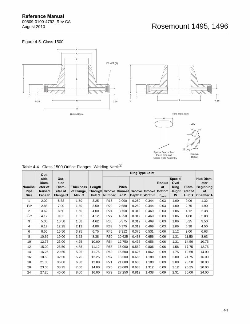
Figure 4-5. Class 1500
Table 4-4. Class 1500 Orifice Flanges, Welding Neck(1)
Nominal Pipe Size
Out-side
Diam-eter of Raised Face R
Out-side
Diam-eter of
Flange O
Thickness of Flange,
Min. C
Length Through
Hub Y
Ring Type Joint
Diam-eter of Hub X
Hub Diam-eter
Beginning of
Chamfer AGroove Number
Pitch Diam-et
er PGroove Depth E
Groove Width F
Radius at
Bottom rmax
Special Oval Ring
Height W
1 2.00 5.88 1.50 3.25 R16 2.000 0.250 0.344 0.03 1.00 2.06 1.32
11/2 2.88 7.00 1.50 3.50 R20 2.688 0.250 0.344 0.03 1.00 2.75 1.90
2 3.62 8.50 1.50 4.00 R24 3.750 0.312 0.469 0.03 1.06 4.12 2.38
21/2 4.12 9.62 1.62 4.12 R27 4.250 0.312 0.469 0.03 1.06 4.88 2.88
3 5.00 10.50 1.88 4.62 R35 5.375 0.312 0.469 0.03 1.06 5.25 3.50
4 6.19 12.25 2.12 4.88 R39 6.375 0.312 0.469 0.03 1.06 6.38 4.50
6 8.50 15.50 3.25 6.75 R46 8.312 0.375 0.531 0.06 1.12 9.00 6.63
8 10.62 19.00 3.62 8.38 R50 10.625 0.438 0.656 0.06 1.31 11.50 8.63
10 12.75 23.00 4.25 10.00 R54 12.750 0.438 0.656 0.06 1.31 14.50 10.75
12 15.00 26.50 4.88 11.12 R58 15.000 0.562 0.806 0.06 1.56 17.75 12.75
14 16.25 29.50 5.25 11.75 R63 16.500 0.625 1.062 0.09 1.75 19.50 14.00
16 18.50 32.50 5.75 12.25 R67 18.500 0.688 1.188 0.09 2.00 21.75 16.00
18 21.00 36.00 6.38 12.88 R71 21.000 0.688 1.188 0.09 2.00 23.50 18.00
20 23.00 38.75 7.00 14.00 R75 23.000 0.688 1.312 0.09 2.12 25.25 20.00
24 27.25 46.00 8.00 16.00 R79 27.250 0.812 1.438 0.09 2.31 30.00 24.00
X
A
B
1
R
O
Raised Face
Y
C
0.25 0.94
1/2 NPT (1)
1
P
Ring Type Joint
Y
CE 0.75
Special One or Two Piece Ring and Orifice Plate Assembly
W
Groove Detail
E
F
23 deg.
r
4-9
Reference Manual00809-0100-4792, Rev CA
August 2010Rosemount 1495, 1496
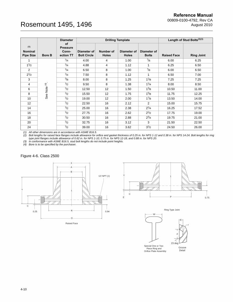
Figure 4-6. Class 2500
(1)
Nominal Pipe Size Bore B
Diameter of
Pressure Conn-
ection TT
Drilling Template Length of Stud Bolts(2)(3) (4)
Diameter of Bolt Circle
Number of Holes
Diameter of Holes
Diameter of Bolts Raised Face Ring Joint
1 1/4 4.00 4 1.00 7/8 6.00 6.25
11/2 1/4 4.88 4 1.12 1 6.25 6.50
2 1/4 6.50 8 1.00 7/8 6.00 6.50
21/2 1/4 7.50 8 1.12 1 6.50 7.00
3 3/8 8.00 8 1.25 11/8 7.25 7.25
4 1/2 9.50 8 1.38 11/4 8.00 8.50
6 1/2 12.50 12 1.50 13/8 10.50 11.00
8 1/2 15.50 12 1.75 15/8 11.75 12.25
10 1/2 19.00 12 2.00 17/8 13.50 14.00
12 1/2 22.50 16 2.12 2 15.00 15.75
14 1/2 25.00 16 2.38 21/4 16.25 17.52
16 1/2 27.75 16 2.62 21/2 17.75 19.00
18 1/2 30.50 16 2.88 23/4 19.75 21.00
20 1/2 32.75 16 3.12 3 21.50 22.50
24 1/2 39.00 16 3.62 31/2 24.50 26.00
(1) All other dimensions are in accordance with ASME B16.5.(2) Bolt lengths for raised face flanges include allowance for orifice and gasket thickness of 0.25 in. for NPS 1-12 and 0.38 in. for NPS 14-24. Bolt lengths for ring
type joint flanges include allowance of 0.62 in. for NPS 1-10, 0.75 in. for NPS 12-18, and 0.88 in. for NPS 20.(3) In conformance with ASME B16.5, stud bolt lengths do not include point heights.(4) Bore is to be specified by the purchaser.
See
Not
e (4
) .
X
A
B
1
R
O
Raised Face
Y
C
0.25 0.94
1/2 NPT (1) 1
P
Ring Type Joint
Y
CE 0.75
Special One or Two Piece Ring and Orifice Plate Assembly
W
Groove Detail
E
F
23 deg.
r
4-10
Reference Manual 00809-0100-4792, Rev CAAugust 2010 Rosemount 1495, 1496
)
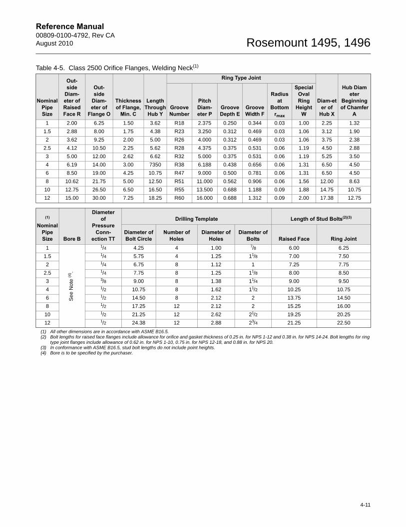
Table 4-5. Class 2500 Orifice Flanges, Welding Neck(1)
Nominal Pipe Size
Out-side
Diam-eter of Raised Face R
Out-side
Diam-eter of
Flange O
Thickness of Flange,
Min. C
Length Through
Hub Y
Ring Type Joint
Diam-eter of
Hub X
Hub Diameter
Beginning of Chamfer
AGroove Number
Pitch Diam-eter P
Groove Depth E
Groove Width F
Radius at
Bottom rmax
Special Oval Ring
Height W
1 2.00 6.25 1.50 3.62 R18 2.375 0.250 0.344 0.03 1.00 2.25 1.32
1.5 2.88 8.00 1.75 4.38 R23 3.250 0.312 0.469 0.03 1.06 3.12 1.90
2 3.62 9.25 2.00 5.00 R26 4.000 0.312 0.469 0.03 1.06 3.75 2.38
2.5 4.12 10.50 2.25 5.62 R28 4.375 0.375 0.531 0.06 1.19 4.50 2.88
3 5.00 12.00 2.62 6.62 R32 5.000 0.375 0.531 0.06 1.19 5.25 3.50
4 6.19 14.00 3.00 7350 R38 6.188 0.438 0.656 0.06 1.31 6.50 4.50
6 8.50 19.00 4.25 10.75 R47 9.000 0.500 0.781 0.06 1.31 6.50 4.50
8 10.62 21.75 5.00 12.50 R51 11.000 0.562 0.906 0.06 1.56 12.00 8.63
10 12.75 26.50 6.50 16.50 R55 13.500 0.688 1.188 0.09 1.88 14.75 10.75
12 15.00 30.00 7.25 18.25 R60 16.000 0.688 1.312 0.09 2.00 17.38 12.75
(1)
Nominal Pipe Size Bore B
Diameter of
Pressure Conn-
ection TT
Drilling Template Length of Stud Bolts(2)(3)
Diameter of Bolt Circle
Number of Holes
Diameter of Holes
Diameter of Bolts Raised Face Ring Joint
1 1/4 4.25 4 1.00 7/8 6.00 6.25 (4
1.5 1/4 5.75 4 1.25 11/8 7.00 7.50
2 1/4 6.75 8 1.12 1 7.25 7.75
2.5 1/4 7.75 8 1.25 11/8 8.00 8.50
3 3/8 9.00 8 1.38 11/4 9.00 9.50
4 1/2 10.75 8 1.62 11/2 10.25 10.75
6 1/2 14.50 8 2.12 2 13.75 14.50
8 1/2 17.25 12 2.12 2 15.25 16.00
10 1/2 21.25 12 2.62 21/2 19.25 20.25
12 1/2 24.38 12 2.88 23/4 21.25 22.50
(1) All other dimensions are in accordance with ASME B16.5.(2) Bolt lengths for raised face flanges include allowance for orifice and gasket thickness of 0.25 in. for NPS 1-12 and 0.38 in. for NPS 14-24. Bolt lengths for ring
type joint flanges include allowance of 0.62 in. for NPS 1-10, 0.75 in. for NPS 12-18, and 0.88 in. for NPS 20.(3) In conformance with ASME B16.5, stud bolt lengths do not include point heights.(4) Bore is to be specified by the purchaser.
See
Not
e (4
) .
4-11

Reference Manual 00809-0100-4792, Rev CAAugust 2010 Rosemount 1495, 1496
1496 WEIGHTS (ESTIMATED)
Weights are in pounds (kilograms).
Estimated weight based on:
ANSI schedule standard pipe
Carbon Steel materials of construction
Flange tap design
Any deviation in configuration may affect estimated weights.
Flange Ratings Line Size2 in. (50 mm) 2.5 in. (64 mm) 3 in. (80 mm) 4 in. (100 mm) 6 in. (150 mm) 8 in. (200 mm) 10 in. (250 mm)
ANSI 150 12 (5.44) 16 (7.27) 20 (9.09) 30 (13.64) 48 (21.82) 78 (35.45) 104 (47.27)
300 18 (8.18) 24 (10.91) 30 (13.64) 50 (22.73) 84 (38.18) 134 (60.91) 182 (82.73)
600 24 (10.91) 36 (16.36) 46 (20.91) 84 (38.18) 162 (73.64) 240 (109.09) 380 (172.73)
900 50 (22.73) 72 (32.73) 82 (37.27) 102 (46.36) 220 (100.00) 350 (159.09) 520 (236.36)
1500 50 (22.73) 72 (32.73) 96 (43.64) 146 (66.36) 330 (150.00) 550 (250.00) 910 (413.64)
2500 84 (38.18) 104 (47.27) 188 (85.45) 290 (131.82) 760 (345.45) 1160 (527.27) 2150 (977.27)
RTJ 300 19 (8.64) 25 (11.36) 31 (14.09) 51 (23.18) 85 (38.63) 136 (61.82) 184 (83.64)
600 25 (11.36) 37 (16.82) 47 (21.36) 85 (38.64) 163 (74.09) 242 (110.00) 382 (173.64)
900 51 (23.18) 73 (33.18) 83 (37.73) 103 (46.82) 221 (100.45) 352 (160.00) 522 (237.27)
1500 51 (23.18) 73 (33.18) 97 (44.09) 147 (66.82) 331 (150.45) 552 (250.91) 912 (414.54)
2500 85 (38.64) 105 (47.73) 189 (85.91) 291 (132.27) 761 (345.91) 1162 (528.18) 2152 (978.18)
Flange Ratings Line Size12 in. (300 mm) 14 in. (350 mm) 16 in. (400 mm) 18 in. (450 mm) 20 in. (500 mm) 22 in. (550 mm) 24 in. (600 mm)
ANSI 150 160 (72.72) 220 (99.79) 280 (127.00) 300 (136.08) 360 (163.29) 450 (204.12) 520 (235.87)
300 280 (127.27) 360 (163.29) 500 (226.79) 640 (290.30) 800 (362.87) 930 (421.84) 1160 (526.17)
600 450 (204.54) 560 (254.01) 780 (353.80) 950 (430.91) 1180 (535.23) 1440 (653.17) 1660 (752.96)
900 650 (295.45) 800 (362.87) 990 (449.05) 1360 (616.88) 1660 (752.96) 2500 (1133.98) 3000 (1360.77)
1500 1380 (627.27) 1880 (852.75) 2500 (1133.98) 3250 (1474.17) 4100 (1859.72) 5200 (2358.68) 6650 (3016.38)
2500 3050 (1386.36) 4050 (1837.04) 5100 (2313.32) 6450 (2925.67) 7200 (3265.86) 8250 (3742.13) 9300 (4218.40)
RTJ 300 282 (128.18) 362 (164.20) 503 (228.16) 643 (291.66) 803 (364.23) 933 (423.20) 1164 (527.98)
600 452 (205.45) 562 (254.92) 783 (355.16) 953 (432.27) 1183 (536.60) 1443 (654.53) 1664 (754.78)
900 652 (296.36) 802 (363.78) 993 (450.42) 1363 (618.24) 1663 (754.32) 2500 (1133.98) 3004 (1362.59)
1500 1382 (628.18) 1882 (853.66) 2503 (1135.34) 3253 (1475.53) 4103 (1861.09) 5100 (2313.32) 6654 (3018.20)
2500 3052 (1387.27) 4100 (1859.73) 5150 (2335.99) 6200 (2812.27) 7300 (3311.22) 8400 (3810.17) 9400 (4263.76)
4-12

Reference Manual 00809-0100-4792, Rev CAAugust 2010 Rosemount 1495, 1496
Appendix A Specifications and Reference Data
Functional Specifications . . . . . . . . . . . . . . . . . . . . . . . . . page A-1Physical Specifications . . . . . . . . . . . . . . . . . . . . . . . . . . . page A-2Sizing and How to Order . . . . . . . . . . . . . . . . . . . . . . . . . . page A-5Rosemount 1495 Configuration . . . . . . . . . . . . . . . . . . . . page A-7Rosemount 1496 Configuration . . . . . . . . . . . . . . . . . . . . page A-10SPECIFICATIONS
Functional Specifications
Service and Flow RangeLiquid, gas or vapor turbulent flow, for pipe Reynold’s Numbers greater than the following:AGA-3: 4,000ASME MFC-3M: 5,000ISO-5167: 5,000
Orifice Plate Operating Limitations
Temperature Limit: Based on flange rating per ANSI B16.5.
Maximum Working Pressure: Based on flange rating per ANSI B16.5.
Service and Flow RangeLiquid, gas or vapor turbulent flow, for pipe Reynold’s Numbers within ISO 5167, AGA Report No. 3/ API 14.3.2, and ASME MFC-3M specifications.
Pipe Sizes2-in. to 24-in. (50 mm to 600 mm). Contact Emerson Process Management for pipe sizes less than 2-in. (50 mm) or greater than 24-in. (600 mm).Operating Limits
1495 Temperature Range:
• –320 to 800 °F (–196 to 427 °C) and differential pressure up to 800 inH20
• 800 to 1200 °F (427 to 649 °C) and differential pressure up to 400 inH20
1496 Temperature Range:
• –320 to 1000 °F (–196 to 538 °C)
www.rosemount.com
Reference Manual00809-0100-4792, Rev CA
August 2010Rosemount 1495, 1496
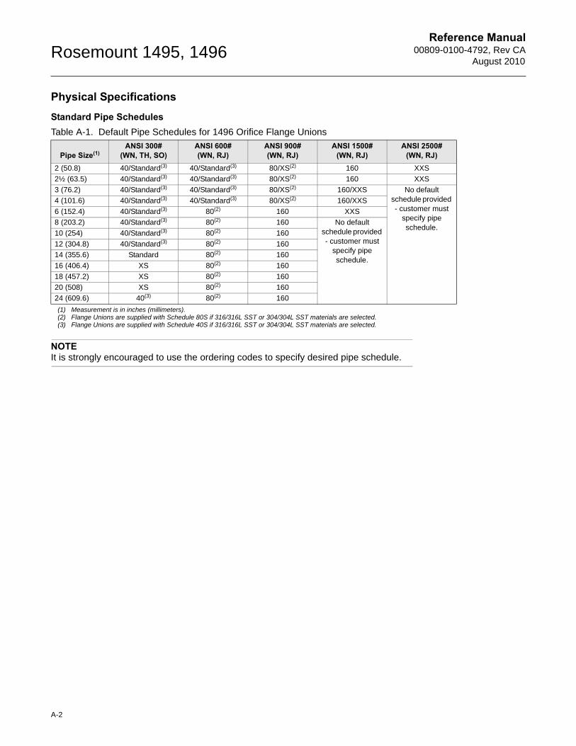
Physical SpecificationsStandard Pipe Schedules Table A-1. Default Pipe Schedules for 1496 Orifice Flange Unions
Pipe Size(1)
(1) Measurement is in inches (millimeters).
ANSI 300# (WN, TH, SO)
ANSI 600# (WN, RJ)
ANSI 900# (WN, RJ)
ANSI 1500# (WN, RJ)
ANSI 2500# (WN, RJ)
2 (50.8) 40/Standard(3) 40/Standard(3) 80/XS(2) 160 XXS
2½ (63.5) 40/Standard(3) 40/Standard(3) 80/XS(2) 160 XXS
3 (76.2) 40/Standard(3) 40/Standard(3) 80/XS(2) 160/XXS No default schedule provided - customer must
specify pipe schedule.
4 (101.6) 40/Standard(3) 40/Standard(3) 80/XS(2) 160/XXS
6 (152.4) 40/Standard(3) 80(2)
(2) Flange Unions are supplied with Schedule 80S if 316/316L SST or 304/304L SST materials are selected.
160 XXS
8 (203.2) 40/Standard(3) 80(2) 160 No default schedule provided - customer must
specify pipe schedule.
10 (254) 40/Standard(3) 80(2) 160
12 (304.8) 40/Standard(3) 80(2) 160
14 (355.6) Standard 80(2) 160
16 (406.4) XS 80(2) 160
18 (457.2) XS 80(2) 160
20 (508) XS 80(2) 160
24 (609.6) 40(3)
(3) Flange Unions are supplied with Schedule 40S if 316/316L SST or 304/304L SST materials are selected.
NOTEIt is strongly encouraged to use the ordering codes to specify desired pipe schedule.
80(2) 160
A-2
Reference Manual 00809-0100-4792, Rev CAAugust 2010
Rosemount 1495, 1496
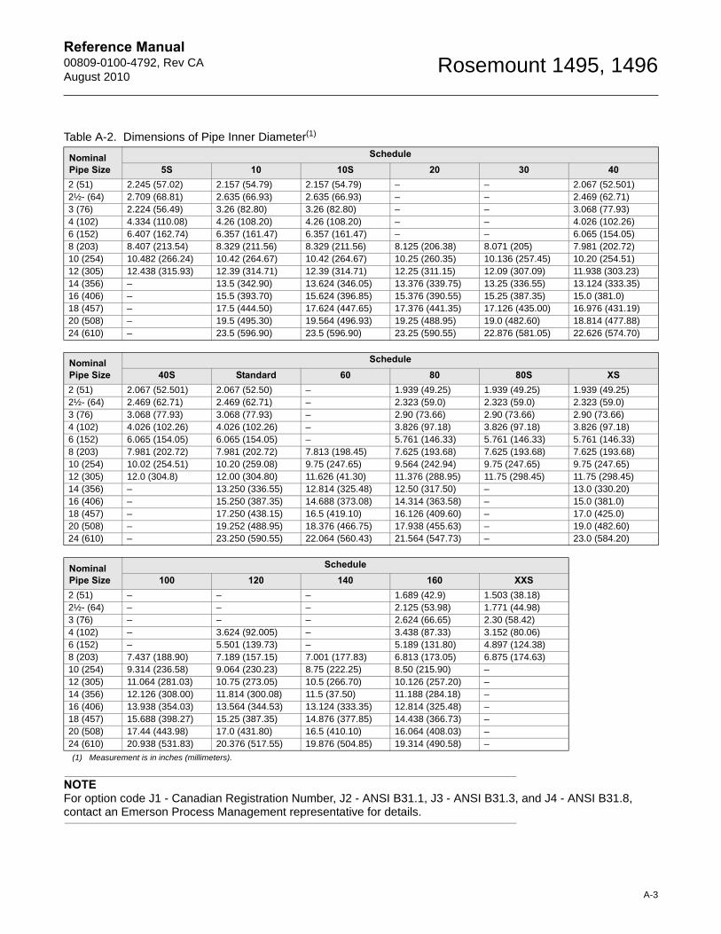
Table A-2. Dimensions of Pipe Inner Diameter(1)
Nominal Pipe Size
Schedule5S 10 10S 20 30 40
2 (51) 2.245 (57.02) 2.157 (54.79) 2.157 (54.79) – – 2.067 (52.501)2½- (64) 2.709 (68.81) 2.635 (66.93) 2.635 (66.93) – – 2.469 (62.71)3 (76) 2.224 (56.49) 3.26 (82.80) 3.26 (82.80) – – 3.068 (77.93)4 (102) 4.334 (110.08) 4.26 (108.20) 4.26 (108.20) – – 4.026 (102.26)6 (152) 6.407 (162.74) 6.357 (161.47) 6.357 (161.47) – – 6.065 (154.05)8 (203) 8.407 (213.54) 8.329 (211.56) 8.329 (211.56) 8.125 (206.38) 8.071 (205) 7.981 (202.72)10 (254) 10.482 (266.24) 10.42 (264.67) 10.42 (264.67) 10.25 (260.35) 10.136 (257.45) 10.20 (254.51)12 (305) 12.438 (315.93) 12.39 (314.71) 12.39 (314.71) 12.25 (311.15) 12.09 (307.09) 11.938 (303.23)14 (356) – 13.5 (342.90) 13.624 (346.05) 13.376 (339.75) 13.25 (336.55) 13.124 (333.35)16 (406) – 15.5 (393.70) 15.624 (396.85) 15.376 (390.55) 15.25 (387.35) 15.0 (381.0)18 (457) – 17.5 (444.50) 17.624 (447.65) 17.376 (441.35) 17.126 (435.00) 16.976 (431.19)20 (508) – 19.5 (495.30) 19.564 (496.93) 19.25 (488.95) 19.0 (482.60) 18.814 (477.88)24 (610) – 23.5 (596.90) 23.5 (596.90) 23.25 (590.55) 22.876 (581.05) 22.626 (574.70)
Nominal Pipe Size
Schedule40S Standard 60 80 80S XS
2 (51) 2.067 (52.501) 2.067 (52.50) – 1.939 (49.25) 1.939 (49.25) 1.939 (49.25)2½- (64) 2.469 (62.71) 2.469 (62.71) – 2.323 (59.0) 2.323 (59.0) 2.323 (59.0)3 (76) 3.068 (77.93) 3.068 (77.93) – 2.90 (73.66) 2.90 (73.66) 2.90 (73.66)4 (102) 4.026 (102.26) 4.026 (102.26) – 3.826 (97.18) 3.826 (97.18) 3.826 (97.18)6 (152) 6.065 (154.05) 6.065 (154.05) – 5.761 (146.33) 5.761 (146.33) 5.761 (146.33)8 (203) 7.981 (202.72) 7.981 (202.72) 7.813 (198.45) 7.625 (193.68) 7.625 (193.68) 7.625 (193.68)10 (254) 10.02 (254.51) 10.20 (259.08) 9.75 (247.65) 9.564 (242.94) 9.75 (247.65) 9.75 (247.65)12 (305) 12.0 (304.8) 12.00 (304.80) 11.626 (41.30) 11.376 (288.95) 11.75 (298.45) 11.75 (298.45)14 (356) – 13.250 (336.55) 12.814 (325.48) 12.50 (317.50) – 13.0 (330.20)16 (406) – 15.250 (387.35) 14.688 (373.08) 14.314 (363.58) – 15.0 (381.0)18 (457) – 17.250 (438.15) 16.5 (419.10) 16.126 (409.60) – 17.0 (425.0)20 (508) – 19.252 (488.95) 18.376 (466.75) 17.938 (455.63) – 19.0 (482.60)24 (610) – 23.250 (590.55) 22.064 (560.43) 21.564 (547.73) – 23.0 (584.20)
Nominal Pipe Size
Schedule100 120 140 160 XXS
2 (51) – – – 1.689 (42.9) 1.503 (38.18)2½- (64) – – – 2.125 (53.98) 1.771 (44.98)3 (76) – – – 2.624 (66.65) 2.30 (58.42)4 (102) – 3.624 (92.005) – 3.438 (87.33) 3.152 (80.06)6 (152) – 5.501 (139.73) – 5.189 (131.80) 4.897 (124.38)8 (203) 7.437 (188.90) 7.189 (157.15) 7.001 (177.83) 6.813 (173.05) 6.875 (174.63)10 (254) 9.314 (236.58) 9.064 (230.23) 8.75 (222.25) 8.50 (215.90) –12 (305) 11.064 (281.03) 10.75 (273.05) 10.5 (266.70) 10.126 (257.20) –14 (356) 12.126 (308.00) 11.814 (300.08) 11.5 (37.50) 11.188 (284.18) –16 (406) 13.938 (354.03) 13.564 (344.53) 13.124 (333.35) 12.814 (325.48) –18 (457) 15.688 (398.27) 15.25 (387.35) 14.876 (377.85) 14.438 (366.73) –20 (508) 17.44 (443.98) 17.0 (431.80) 16.5 (410.10) 16.064 (408.03) –24 (610) 20.938 (531.83) 20.376 (517.55) 19.876 (504.85) 19.314 (490.58) –
(1) Measurement is in inches (millimeters).
NOTEFor option code J1 - Canadian Registration Number, J2 - ANSI B31.1, J3 - ANSI B31.3, and J4 - ANSI B31.8, contact an Emerson Process Management representative for details.
A-3
Reference Manual00809-0100-4792, Rev CA
August 2010Rosemount 1495, 1496
A-4
Materials of Construction1495 Orifice Plate304/304L or 316/316L Stainless Steel ASTM A240; DIN 1.4571 (316Ti SST)(1); Alloy C-276 ASTM B575; or Alloy 400 ASTM B127.
Orifice Bore SizesStandard bore sizes are in 1/8-in. (3.2 mm) increments from ½-in. (12.7 mm) to 4-in. (101.6 mm) and in 1/4-in. (6.3 mm) increments from 41/4 to 6-in. (107.95 mm to 152.4 mm).
If required, Emerson Process Management can determine the orifice bore. Basic flow data is required at the time of order, see “Calculation Data Sheet” on page C-1.Bore tolerances are within AGA and ASME specifications. Available options allow the user to have the Rosemount 1495 sized for specific operating conditions. The “Orifice Plate Drawings” on page 3-6 specifies the physical parameters of the orifice from a detailed sizing calculation.
1496 Flange UnionsOrifice Flanges (ANSI B16.36): Carbon Steel ASTM A105 / A350; Stainless Steel ASTM A182; Alloy C-276 ASTM B564/575; or Alloy 400 ASTM B564/127; DIN 1.4571 (316Ti SST)(1); DIN 1.0460 (carbon steel)(1).
Flange Mounting Hardware• Studs: Carbon Steel ASTM A193 Grade B7M• Nuts: Carbon Steel ASTM A194 Gr 2H• Gaskets: Non-asbestos ring type, Durlon® 8500 Green, Klingersil C4400, or equivalent• Pipe Plugs: Match flange material
Pressure TapsPressure tap connections are ½ -in. (12.7 mm) NPT and 180° apart as standard. The tap hole
diameter is ¼-in. (6.35 mm) for 2-in. (51 mm) size, 3/8-in. (9.6 mm) for 2½ -in. (63.5 mm) size and
3-in. (76.2 mm), and ½-in. (12.7 mm) for 4-in. (101.6 mm) and larger sizes.
Return of Materials To expedite the return process outside the United States, contact the nearest sales representative.
Within the United States, call the Rosemount National Response Center using the 1-800-654-RSMT (7768) toll-free number. This center, available 24 hours a day, will assist you with any needed information or materials.
The center will ask for product model and serial numbers, and will provide a Return Material Authorization (RMA) number. The center will also ask for the name of the process material to which the product was last exposed.
The Rosemount National Response Center will detail the additional information and procedures necessary to return goods exposed to hazardous substances.
(1) May not be available in all world areas.
People who handle products exposed to a hazardous substance can avoid injury if they are informed and understand the hazard. If the product being returned was exposed to a hazardous substance as defined by OSHA, a copy of the required Material Safety Data Sheet (MSDS) for each hazardous substance identified must be included with the returned goods.
Reference Manual 00809-0100-4792, Rev CAAugust 2010
Rosemount 1495, 1496
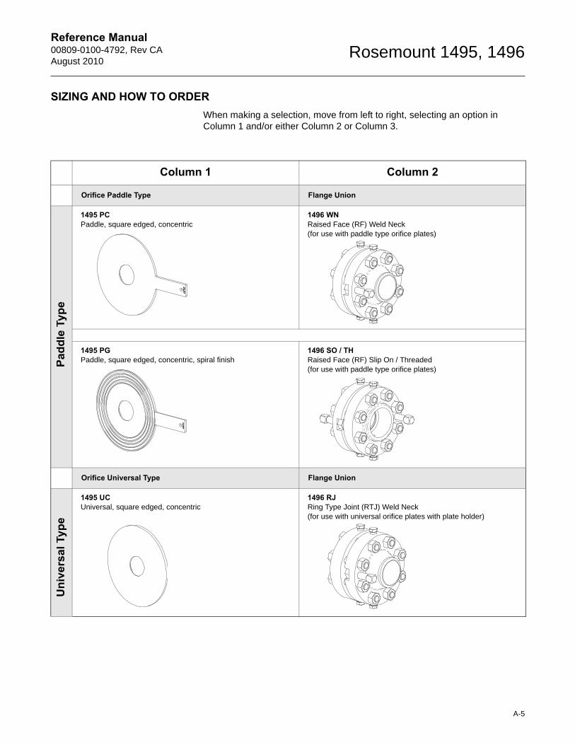
SIZING AND HOW TO ORDERWhen making a selection, move from left to right, selecting an option in Column 1 and/or either Column 2 or Column 3.
Column 1 Column 2
Orifice Paddle Type Flange Union
1495 PCPaddle, square edged, concentric
1496 WNRaised Face (RF) Weld Neck(for use with paddle type orifice plates)
1495 PGPaddle, square edged, concentric, spiral finish
1496 SO / THRaised Face (RF) Slip On / Threaded(for use with paddle type orifice plates)
Orifice Universal Type Flange Union
1495 UCUniversal, square edged, concentric
1496 RJRing Type Joint (RTJ) Weld Neck (for use with universal orifice plates with plate holder)
Padd
le T
ype
Uni
vers
al T
ype
A-5
Reference Manual00809-0100-4792, Rev CA
August 2010Rosemount 1495, 1496
A-6
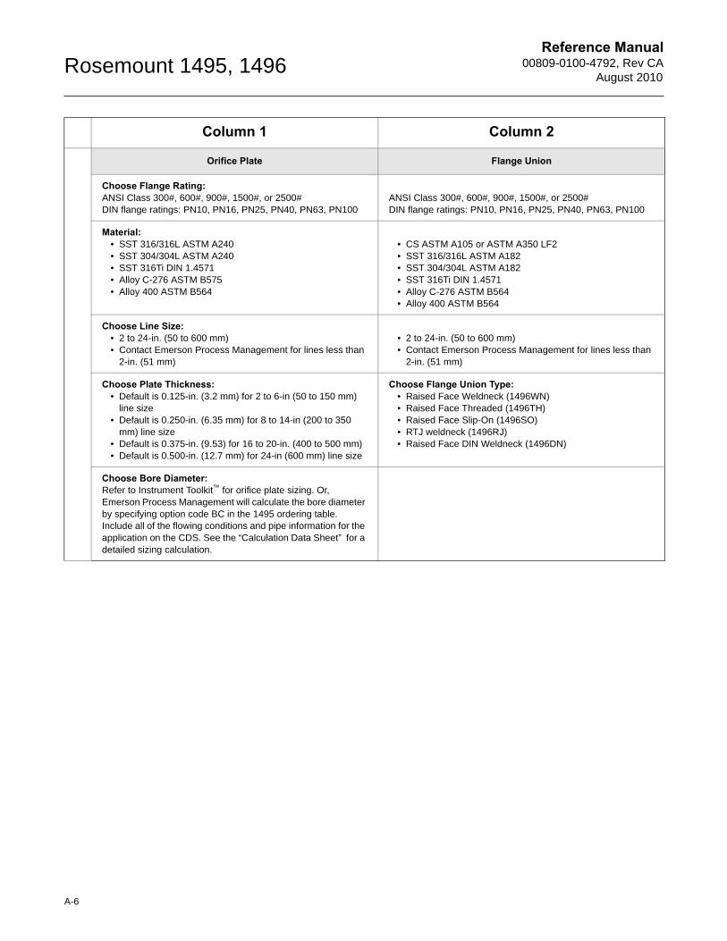
Orifice Plate Flange Union
Choose Flange Rating:ANSI Class 300#, 600#, 900#, 1500#, or 2500#DIN flange ratings: PN10, PN16, PN25, PN40, PN63, PN100
ANSI Class 300#, 600#, 900#, 1500#, or 2500#DIN flange ratings: PN10, PN16, PN25, PN40, PN63, PN100
Material:• SST 316/316L ASTM A240• SST 304/304L ASTM A240• SST 316Ti DIN 1.4571• Alloy C-276 ASTM B575• Alloy 400 ASTM B564
• CS ASTM A105 or ASTM A350 LF2• SST 316/316L ASTM A182• SST 304/304L ASTM A182• SST 316Ti DIN 1.4571• Alloy C-276 ASTM B564• Alloy 400 ASTM B564
Choose Line Size:• 2 to 24-in. (50 to 600 mm)• Contact Emerson Process Management for lines less than
2-in. (51 mm)
• 2 to 24-in. (50 to 600 mm)• Contact Emerson Process Management for lines less than
2-in. (51 mm)
Choose Plate Thickness:• Default is 0.125-in. (3.2 mm) for 2 to 6-in (50 to 150 mm)
line size• Default is 0.250-in. (6.35 mm) for 8 to 14-in (200 to 350
mm) line size• Default is 0.375-in. (9.53) for 16 to 20-in. (400 to 500 mm)• Default is 0.500-in. (12.7 mm) for 24-in (600 mm) line size
Choose Flange Union Type:• Raised Face Weldneck (1496WN)• Raised Face Threaded (1496TH)• Raised Face Slip-On (1496SO)• RTJ weldneck (1496RJ)• Raised Face DIN Weldneck (1496DN)
Choose Bore Diameter:Refer to Instrument Toolkit™ for orifice plate sizing. Or, Emerson Process Management will calculate the bore diameter by specifying option code BC in the 1495 ordering table. Include all of the flowing conditions and pipe information for the application on the CDS. See the “Calculation Data Sheet” for a detailed sizing calculation.
Column 1 Column 2
Reference Manual 00809-0100-4792, Rev CAAugust 2010
Rosemount 1495, 1496
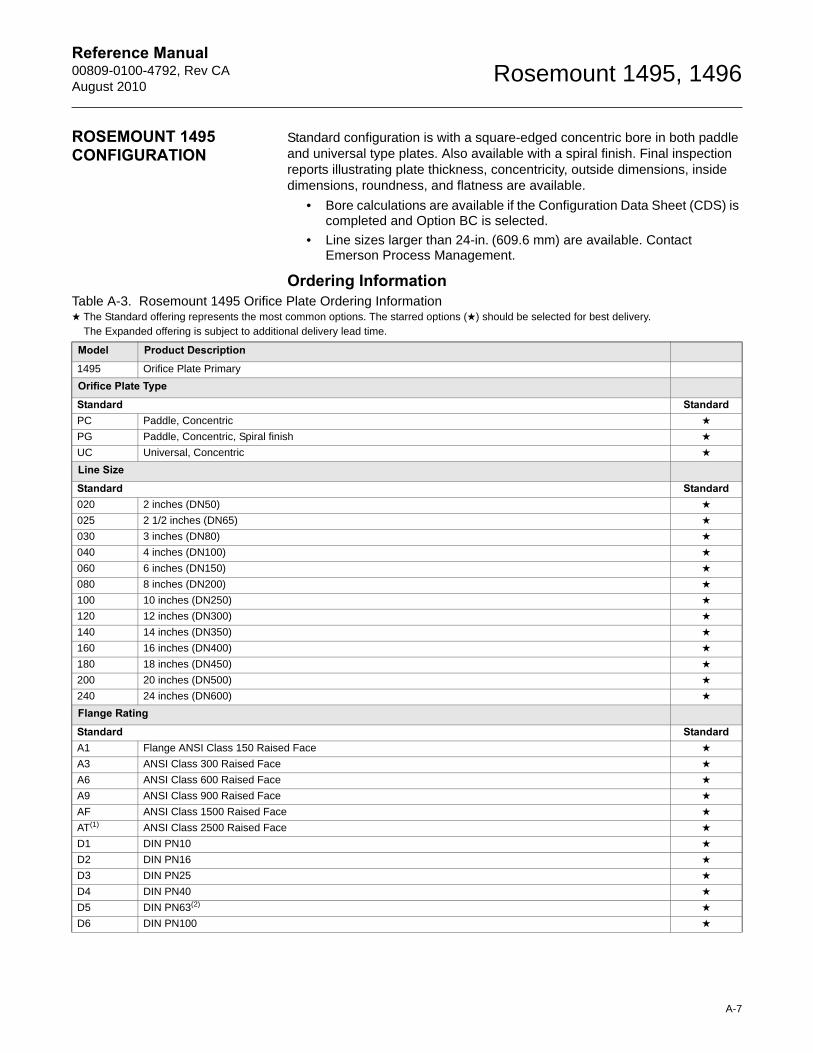
ROSEMOUNT 1495 CONFIGURATION
Standard configuration is with a square-edged concentric bore in both paddle and universal type plates. Also available with a spiral finish. Final inspection reports illustrating plate thickness, concentricity, outside dimensions, inside dimensions, roundness, and flatness are available.
• Bore calculations are available if the Configuration Data Sheet (CDS) is completed and Option BC is selected.
• Line sizes larger than 24-in. (609.6 mm) are available. Contact Emerson Process Management.
Ordering InformationTable A-3. Rosemount 1495 Orifice Plate Ordering Information★ The Standard offering represents the most common options. The starred options (★) should be selected for best delivery.__The Expanded offering is subject to additional delivery lead time.
Model Product Description
1495 Orifice Plate Primary
Orifice Plate Type
Standard StandardPC Paddle, Concentric ★
PG Paddle, Concentric, Spiral finish ★
UC Universal, Concentric ★
Line Size
Standard Standard020 2 inches (DN50) ★
025 2 1/2 inches (DN65) ★
030 3 inches (DN80) ★
040 4 inches (DN100) ★
060 6 inches (DN150) ★
080 8 inches (DN200) ★
100 10 inches (DN250) ★
120 12 inches (DN300) ★
140 14 inches (DN350) ★
160 16 inches (DN400) ★
180 18 inches (DN450) ★
200 20 inches (DN500) ★
240 24 inches (DN600) ★
Flange Rating
Standard StandardA1 Flange ANSI Class 150 Raised Face ★
A3 ANSI Class 300 Raised Face ★
A6 ANSI Class 600 Raised Face ★
A9 ANSI Class 900 Raised Face ★
AF ANSI Class 1500 Raised Face ★
AT(1) ANSI Class 2500 Raised Face ★
D1 DIN PN10 ★
D2 DIN PN16 ★
D3 DIN PN25 ★
D4 DIN PN40 ★
D5 DIN PN63(2) ★
D6 DIN PN100 ★
A-7

Reference Manual00809-0100-4792, Rev CA
August 2010Rosemount 1495, 1496
ExpandedR3 Flange ANSI Class 300 Ring Joint
R6 Flange ANSI Class 600 Ring Joint
R9 Flange ANSI Class 900 Ring Joint
RF Flange ANSI Class 1500 Ring Joint
RT Flange ANSI Class 2500 Ring Joint
Orifice Plate Material Type
Standard StandardS 316/316L Stainless Steel ★
T DIN 1.4571 (316Ti Stainless Steel) ★
L 304/304L Stainless Steel ★
ExpandedH Alloy C-276
M Alloy 400
Plate Thickness
Standard StandardA 0.125-in. (3.2 mm) – default for line size 2 to 6-in. (50 to 150 mm) ★
B 0.250-in. (6.35 mm) – default for line size 8 to 14-in. (200 to 350 mm) ★
C 0.375 in. (9.53 mm) - default for line size 16 to 20-in. (400 to 500 mm) ★
D 0.500-in. (12.7 mm) – default for line size 24-in. (600 mm) ★
E(3) Plate Thickness per DIN 19206 ★
Bore
Standard StandardXXXXX Bore (XXXXX = XX.XXX) ★
Options (Include with selected model number)
Bore CalculationStandard StandardBC Bore Calculation ★
Drain / Vent HoleStandard StandardDV(4) Drain / Vent Hole ★
Plate HolderStandard StandardPH(5) Plate Holder for RTJ Flanges ★
Alternate Bore TypeStandard StandardTC Conical Entrance Bore ★
TE(4) Eccentric Bore ★
TS(4) Segmental Bore ★
TQ Quandrant Edged Bore ★
RO(6) Restriction Orifice Plate ★
Alternate Pipe ScheduleStandard StandardFA(7) Schedule 5S ★
FB(7) Schedule 10 ★
FC(7) Schedule 10S ★
FD(7) Schedule 20 ★
Table A-3. Rosemount 1495 Orifice Plate Ordering Information★ The Standard offering represents the most common options. The starred options (★) should be selected for best delivery.__The Expanded offering is subject to additional delivery lead time.
A-8
Reference Manual 00809-0100-4792, Rev CAAugust 2010
Rosemount 1495, 1496
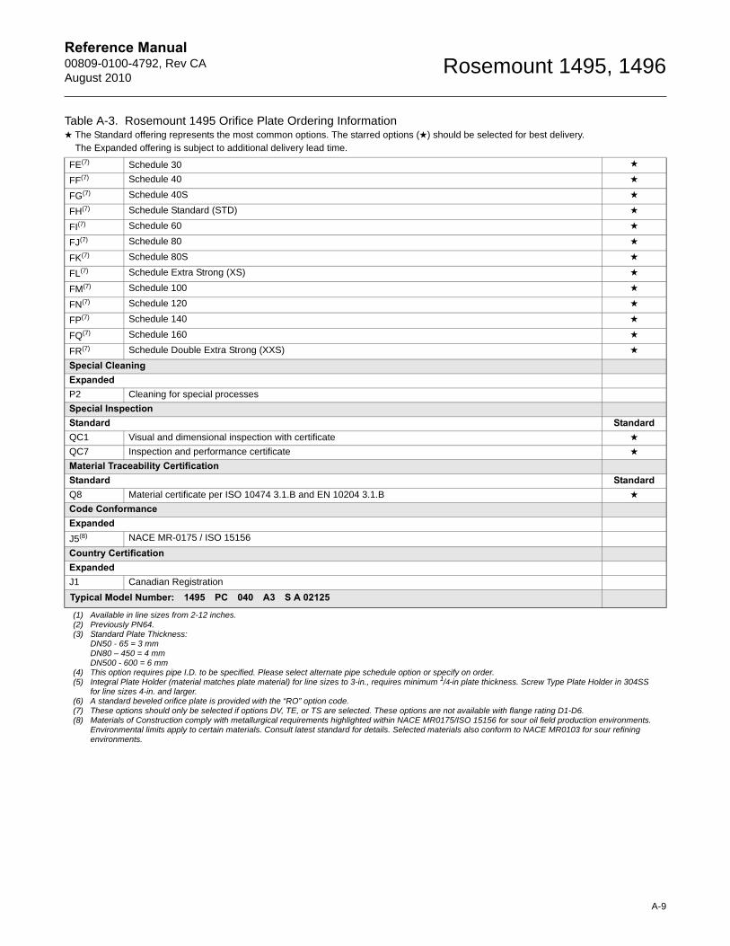
FE(7) Schedule 30 ★
FF(7) Schedule 40 ★
FG(7) Schedule 40S ★
FH(7) Schedule Standard (STD) ★
FI(7) Schedule 60 ★
FJ(7) Schedule 80 ★
FK(7) Schedule 80S ★
FL(7) Schedule Extra Strong (XS) ★
FM(7) Schedule 100 ★
FN(7) Schedule 120 ★
FP(7) Schedule 140 ★
FQ(7) Schedule 160 ★
FR(7) Schedule Double Extra Strong (XXS) ★
Special CleaningExpandedP2 Cleaning for special processes
Special InspectionStandard StandardQC1 Visual and dimensional inspection with certificate ★
QC7 Inspection and performance certificate ★
Material Traceability CertificationStandard StandardQ8 Material certificate per ISO 10474 3.1.B and EN 10204 3.1.B ★
Code ConformanceExpandedJ5(8) NACE MR-0175 / ISO 15156
Country CertificationExpandedJ1 Canadian Registration
Typical Model Number: 1495 PC 040 A3 S A 02125
(1) Available in line sizes from 2-12 inches.(2) Previously PN64.(3) Standard Plate Thickness:
DN50 - 65 = 3 mmDN80 – 450 = 4 mmDN500 - 600 = 6 mm
(4) This option requires pipe I.D. to be specified. Please select alternate pipe schedule option or specify on order.(5) Integral Plate Holder (material matches plate material) for line sizes to 3-in., requires minimum 1/4-in plate thickness. Screw Type Plate Holder in 304SS
for line sizes 4-in. and larger.(6) A standard beveled orifice plate is provided with the “RO” option code.(7) These options should only be selected if options DV, TE, or TS are selected. These options are not available with flange rating D1-D6. (8) Materials of Construction comply with metallurgical requirements highlighted within NACE MR0175/ISO 15156 for sour oil field production environments.
Environmental limits apply to certain materials. Consult latest standard for details. Selected materials also conform to NACE MR0103 for sour refining environments.
Table A-3. Rosemount 1495 Orifice Plate Ordering Information★ The Standard offering represents the most common options. The starred options (★) should be selected for best delivery.__The Expanded offering is subject to additional delivery lead time.
A-9
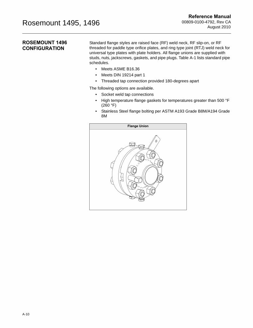
Reference Manual00809-0100-4792, Rev CA
August 2010Rosemount 1495, 1496
ROSEMOUNT 1496 CONFIGURATION
Standard flange styles are raised face (RF) weld neck, RF slip-on, or RF threaded for paddle type orifice plates, and ring type joint (RTJ) weld neck for universal type plates with plate holders. All flange unions are supplied with studs, nuts, jackscrews, gaskets, and pipe plugs. Table A-1 lists standard pipe schedules.
• Meets ASME B16.36
• Meets DIN 19214 part 1
• Threaded tap connection provided 180-degrees apart
The following options are available.
• Socket weld tap connections
• High temperature flange gaskets for temperatures greater than 500 °F (260 °F)
• Stainless Steel flange bolting per ASTM A193 Grade B8M/A194 Grade 8M
Flange Union
A-10
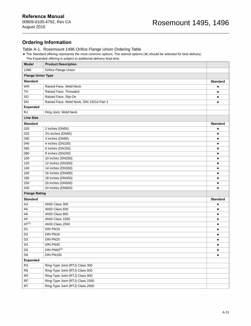
Reference Manual 00809-0100-4792, Rev CAAugust 2010
Rosemount 1495, 1496
Ordering InformationTable A-1. Rosemount 1496 Orifice Flange Union Ordering Table★ The Standard offering represents the most common options. The starred options (★) should be selected for best delivery.__The Expanded offering is subject to additional delivery lead time.
Model Product Description
1496 Orifice Flange Union
Flange Union Type
Standard StandardWN Raised Face, Weld Neck ★
TH Raised Face, Threaded ★
SO Raised Face, Slip-On ★
DN Raised Face, Weld Neck, DIN 19214 Part 1 ★
ExpandedRJ Ring Joint, Weld Neck
Line Size
Standard Standard020 2 inches (DN50) ★
025 2½-inches (DN65) ★
030 3 inches (DN80) ★
040 4 inches (DN100) ★
060 6 inches (DN150) ★
080 8 inches (DN200) ★
100 10 inches (DN250) ★
120 12 inches (DN300) ★
140 14 inches (DN350) ★
160 16 inches (DN400) ★
180 18 inches (DN450) ★
200 20 inches (DN500) ★
240 24 inches (DN600) ★
Flange Rating
Standard StandardA3 ANSI Class 300 ★
A6 ANSI Class 600 ★
A9 ANSI Class 900 ★
AF ANSI Class 1500 ★
AT(1) ANSI Class 2500 ★
D1 DIN PN10 ★
D2 DIN PN16 ★
D3 DIN PN25 ★
D4 DIN PN40 ★
D5 DIN PN63(2) ★
D6 DIN PN100 ★
ExpandedR3 Ring-Type Joint (RTJ) Class 300
R6 Ring-Type Joint (RTJ) Class 600
R9 Ring-Type Joint (RTJ) Class 900
RF Ring-Type Joint (RTJ) Class 1500
RT Ring-Type Joint (RTJ) Class 2500
A-11
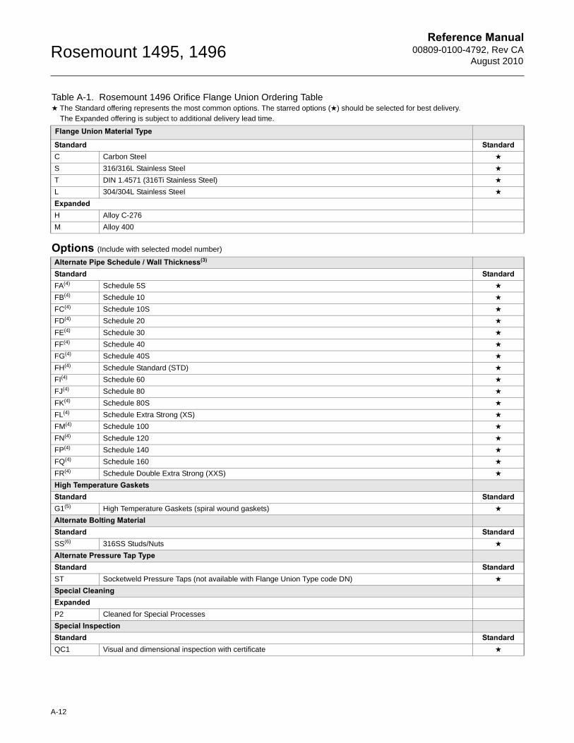
Reference Manual00809-0100-4792, Rev CA
August 2010Rosemount 1495, 1496
Flange Union Material Type
Standard StandardC Carbon Steel ★
S 316/316L Stainless Steel ★
T DIN 1.4571 (316Ti Stainless Steel) ★
L 304/304L Stainless Steel ★
ExpandedH Alloy C-276
M Alloy 400
Options (Include with selected model number)
Alternate Pipe Schedule / Wall Thickness(3)
Standard StandardFA(4) Schedule 5S ★
FB(4) Schedule 10 ★
FC(4) Schedule 10S ★
FD(4) Schedule 20 ★
FE(4) Schedule 30 ★
FF(4) Schedule 40 ★
FG(4) Schedule 40S ★
FH(4) Schedule Standard (STD) ★
FI(4) Schedule 60 ★
FJ(4) Schedule 80 ★
FK(4) Schedule 80S ★
FL(4) Schedule Extra Strong (XS) ★
FM(4) Schedule 100 ★
FN(4) Schedule 120 ★
FP(4) Schedule 140 ★
FQ(4) Schedule 160 ★
FR(4) Schedule Double Extra Strong (XXS) ★
High Temperature GasketsStandard StandardG1(5) High Temperature Gaskets (spiral wound gaskets) ★
Alternate Bolting MaterialStandard StandardSS(6) 316SS Studs/Nuts ★
Alternate Pressure Tap TypeStandard StandardST Socketweld Pressure Taps (not available with Flange Union Type code DN) ★
Special CleaningExpandedP2 Cleaned for Special Processes
Special InspectionStandard StandardQC1 Visual and dimensional inspection with certificate ★
Table A-1. Rosemount 1496 Orifice Flange Union Ordering Table★ The Standard offering represents the most common options. The starred options (★) should be selected for best delivery.__The Expanded offering is subject to additional delivery lead time.
A-12
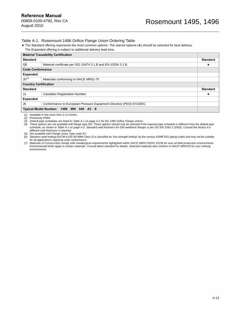
Reference Manual 00809-0100-4792, Rev CAAugust 2010
Rosemount 1495, 1496
Material Traceability CertificationStandard StandardQ8 Material certificate per ISO 10474 3.1.B and EN 10204 3.1.B ★
Code ConformanceExpandedJ5(7) Materials conforming to NACE MR01-75
Country CertificationStandard StandardJ1 Canadian Registration Number ★
ExpandedJ6 Conformance to European Pressure Equipment Directive (PED) 97/23/EC
Typical Model Number: 1496 WN 040 A3 S
(1) Available in line sizes from 2-12 inches.(2) Previously PN64.(3) Default pipe schedules are listed in Table A-1 on page A-2 for the 1496 Orifice Flange Unions.(4) These options are not available with flange type DN. These options should only be selected if the required pipe schedule is different from the default pipe
schedule, as shown in Table A-1 on page A-2. Standard wall thickness for DIN weldneck flanges is per ISO EN 1092-1 (2002). Consult the factory if a different wall thickness is required.
(5) Not available with Flange Union Type code RJ.(6) Stainless steel bolting (ASTM A193 GR B8M Class 2) is classified as “low strength bolting” by the various ASME B31 piping codes and may not be suitable
for all applications requiring code conformance.(7) Materials of Construction comply with metallurgical requirements highlighted within NACE MR0175/ISO 15156 for sour oil field production environments.
Environmental limits apply to certain materials. Consult latest standard for details. Selected materials also conform to NACE MR0103 for sour refining environments.
Table A-1. Rosemount 1496 Orifice Flange Union Ordering Table★ The Standard offering represents the most common options. The starred options (★) should be selected for best delivery.__The Expanded offering is subject to additional delivery lead time.
A-13

Reference Manual00809-0100-4792, Rev CA
August 2010Rosemount 1495, 1496
A-14
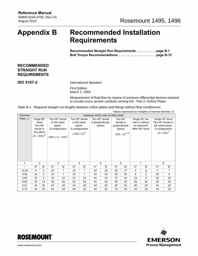
Reference Manual00809-0100-4792, Rev CAAugust 2010 Rosemount 1495, 1496
Appendix B Recommended Installation Requirements
Recommended Straight Run Requirements . . . . . . . . . . . page B-1Bolt Torque Recommendations . . . . . . . . . . . . . . . . . . . . . page B-12RECOMMENDED STRAIGHT RUN REQUIREMENTS
ISO 5167-2 International Standard
First EditionMarch 1, 2003
Measurement of fluid flow by means of pressure differential devices inserted in circular-cross section conduits running full - Part 2: Orifice Plates
Table B-1. Required straight run lengths between orifice plates and fittings without flow conditioners.Values expressed as multiples of internal diameter, D
Diameter Ratio,
Upstream (inlet) side of orifice plate
Single 90° bend
Two 90° bends in any plane
Two 90° bends in the same
plane: S-configuration
Two 90° bends in the same
plane: S-configuration
Two 90° bends in perpendicular
planes
Two 90° bends in
perpendicular planes
Single 90° tee with or without an extension
Mitre 90° bend
Single 45° bendTwo 45° bends in the same plane: S-configuration
1 2 3 4 5 6 7 8
-- Ae Bf Ae Bf Ae Bf Ae Bf Ae Bf Ae Bf Ae Bf
0.20 6 3 10 g 10 g 19 18 34 17 3 g 7 g
0.40 16 3 10 g 10 g 44 18 50 25 9 3 30 9
0.50 22 9 18 10 22 10 44 18 75 34 19 9 30 18
0.60 42 13 30 18 42 18 44 18 65 25 29 18 30 18
0.67 44 20 44 18 44 20 44 20 60 18 36 18 44 18
0.75 44 20 44 18 44 22 44 20 75 18 44 18 44 18
30D S 10D a10D S a 5D S a b S 2D a
S 30D a
www.rosemount.com

Reference Manual00809-0100-4792, Rev CA
August 2010Rosemount 1495, 1496
NOTE 1The minimum straight lengths required are the lengths between various fittings located upstream or downstream of the orifice plate and the orifice plate itself. Straight lengths shall be measured from the downstream end of the curved portion of the nearest (or only) bend or of the tee or the downstream end of the curved or conical portion of the reducer or the expander.
NOTE 2Most of the bends on which the lengths in this table are based had a radius of curvature equal to 1.5D.
a S is the separation between the two bends measured from the downstream end of the curved portion of the upstream end to the upstream end ofthe curved portion of the downstream bend.
b This is not a good upstream installation; a flow conditioner should be used where possible.c The installation of thermometer pockets or wells will not alter the required minimum upstream straight lengths for the other fittings.d A thermometer pocket or well of diameter between 0.03D and 0.13D may be installed provided that the value in Columns A and B are increased to 20
and 10 respectively. Such an installation is not, however, recommended.e Column A for each fitting gives lengths corresponding to “zero additional uncertainty” values (see 6.2.3).f Column B for each fitting gives lengths corresponding to “0.5% additional uncertainty” values (see 6.2.4).g The straight length in Column A gives zero additional uncertainty; data are not available for shorter straight lengths which could be used to give the
required straight lengths for Column B.h 95D is required for ReD > 2 x 10⁶ if S < 2D.
Diameter Ratio,
Upstream (inlet) side of orifice plate
Concentric reducer 2D to D over a length of
1.5D to 3D
Concentric reducer 0.5D to D over a length of D to 2D
Full bore ball valve or gate
valve fully open
Abrupt symmetrical reduction
Thermometer pocket or
well c of diameter0.03Dd
Fittings (columns 2 to 11) and the densitometer
1 9 10 11 12 13 14
-- Ae Bf Ae Bf Ae Bf Ae Bf Ae Bf Ae Bf
0.20 5 g 6 g 12 6 30 15 5 3 4 2
0.40 5 g 12 8 12 6 30 15 5 3 6 3
0.50 8 5 20 9 12 6 30 15 5 3 6 3
0.60 9 5 26 11 14 7 30 15 5 3 7 3.5
0.67 12 6 28 14 18 9 30 15 5 3 7 3.5
0.75 13 8 36 18 24 12 30 15 5 3 8 4
Table B-2. Permitted range of straight lengths between an orifice plate and a 19-tube bundle flow straightener (1998) downstream of fittings located at a distance, Lf, from the orifice plate
Values expressed as multiples of internal diameter, D
Diameter Ratio,
Single 90° bendb Two 90° bendsb in perpendicular planes(2D S)a
Single 90° tee
30 > Lf 18 Lf 30 30 > Lf 18 Lf 30 30 > Lf 18 Lf 30
1 2 3 4 5 6 7
-- Ac Bd Ac Bd Ac Bd Ac Bd Ac Bd Ac Bd
0.20 5 to 14.5 1 to ne 5 to 25 1 to ne 5 to 14.5 1 to ne 5 to 25 1 to ne 5 to 14.5 1 to ne 1 to 25 1 to ne
0.40 5 to 14.5 1 to ne 5 to 25 1 to ne 5 to 14.5 1 to ne 5 to 25 1 to ne 5 to 14.5 1 to ne 1 to 25 1 to ne
0.50 11.5 to 14.5
3 to ne 11.5 to 25
3 to ne 9.5 to 14.5
3 to ne 9 to 25 1 to ne 11 to 13 1 to ne 9 to 23 1 to ne
0.60 12 to 13 5 to ne 12 to 25 5 to ne 13.5 to 14.5
5 to ne 9 to 25 1 to ne fh 7 to ne 11 to 16 1 to ne
0.67 13 7 to ne 13 to 16.5
7 to ne 13 to 14.5
7 to ne 10 to 16 5 to ne f 8 to ne 11 to 13 6 to ne
0.75 14 8 to ne 14 to 16.5
8 to ne f 9.5 to ne 12 to 12.5
8 to ne f 9 to ne 12 to 14 7 to ne
Recom-mended
13 for 0.67
13 for 0.75
14 to 16.5 for 0.75
14 to 16.5 for 0.75
13.5 to 14.5 for 0.67
13.5 to 14.5 for 0.75
12 to 12.5 for 0.75
12 to 12.5 for 0.75
13 for 0.54
13 for 0.75
12 to 13 for 0.75
12 to 13 for 0.75
B-2
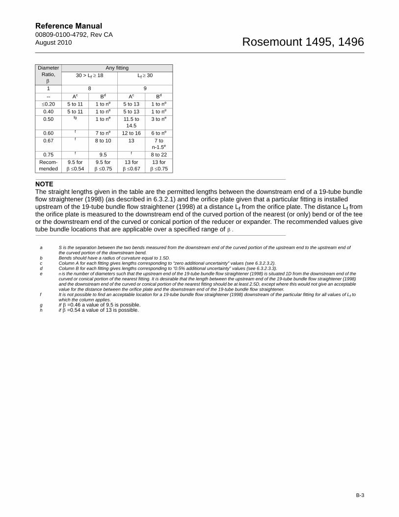
Reference Manual00809-0100-4792, Rev CAAugust 2010 Rosemount 1495, 1496
NOTEThe straight lengths given in the table are the permitted lengths between the downstream end of a 19-tube bundle flow straightener (1998) (as described in 6.3.2.1) and the orifice plate given that a particular fitting is installed upstream of the 19-tube bundle flow straightener (1998) at a distance Lf from the orifice plate. The distance Lf from the orifice plate is measured to the downstream end of the curved portion of the nearest (or only) bend or of the tee or the downstream end of the curved or conical portion of the reducer or expander. The recommended values give tube bundle locations that are applicable over a specified range of .
a S is the separation between the two bends measured from the downstream end of the curved portion of the upstream end to the upstream end ofthe curved portion of the downstream bend.
b Bends should have a radius of curvature equal to 1.5D.c Column A for each fitting gives lengths corresponding to “zero additional uncertainty” values (see 6.3.2.3.2).d Column B for each fitting gives lengths corresponding to “0.5% additional uncertainty” values (see 6.3.2.3.3).e n is the number of diameters such that the upstream end of the 19-tube bundle flow straightener (1998) is situated 1D from the downstream end of the
curved or conical portion of the nearest fitting. It is desirable that the length between the upstream end of the 19-tube bundle flow straightener (1998) and the downstream end of the curved or conical portion of the nearest fitting should be at least 2.5D, except where this would not give an acceptable value for the distance between the orifice plate and the downstream end of the 19-tube bundle flow straightener.
f It is not possible to find an acceptable location for a 19-tube bundle flow straightener (1998) downstream of the particular fitting for all values of Lf to which the column applies.
g If =0.46 a value of 9.5 is possible.h if =0.54 a value of 13 is possible.
Diameter Ratio,
Any fitting
30 > Lf 18 Lf 30
1 8 9
-- Ac Bd Ac Bd
0.20 5 to 11 1 to ne 5 to 13 1 to ne
0.40 5 to 11 1 to ne 5 to 13 1 to ne
0.50 fg 1 to ne 11.5 to 14.5
3 to ne
0.60 f 7 to ne 12 to 16 6 to ne
0.67 f 8 to 10 13 7 to n-1.5e
0.75 f 9.5 f 8 to 22
Recom-mended
9.5 for 0.54
9.5 for 0.75
13 for 0.67
13 for 0.75
B-3

Reference Manual00809-0100-4792, Rev CA
August 2010Rosemount 1495, 1496
Figure B-1. Examples of Installations With a 19-Tube Bundle Flow Straightener Downstream of a Single Bend
1 Position of any fitting placed at any distance upstream of the single bend.2 Position of previous fitting placed before straight length upstream of the single bend.
3D2D 13D± 0.25D
30D
3D2D
13D12D
30D18D
15D
1
2
B-4
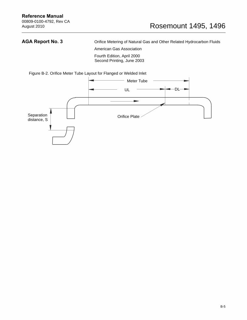
Reference Manual00809-0100-4792, Rev CAAugust 2010 Rosemount 1495, 1496
AGA Report No. 3 Orifice Metering of Natural Gas and Other Related Hydrocarbon Fluids
American Gas Association
Fourth Edition, April 2000Second Printing, June 2003
Figure B-2. Orifice Meter Tube Layout for Flanged or Welded Inlet
Meter Tube
UL DL
Orifice PlateSeparationdistance, S
B-5
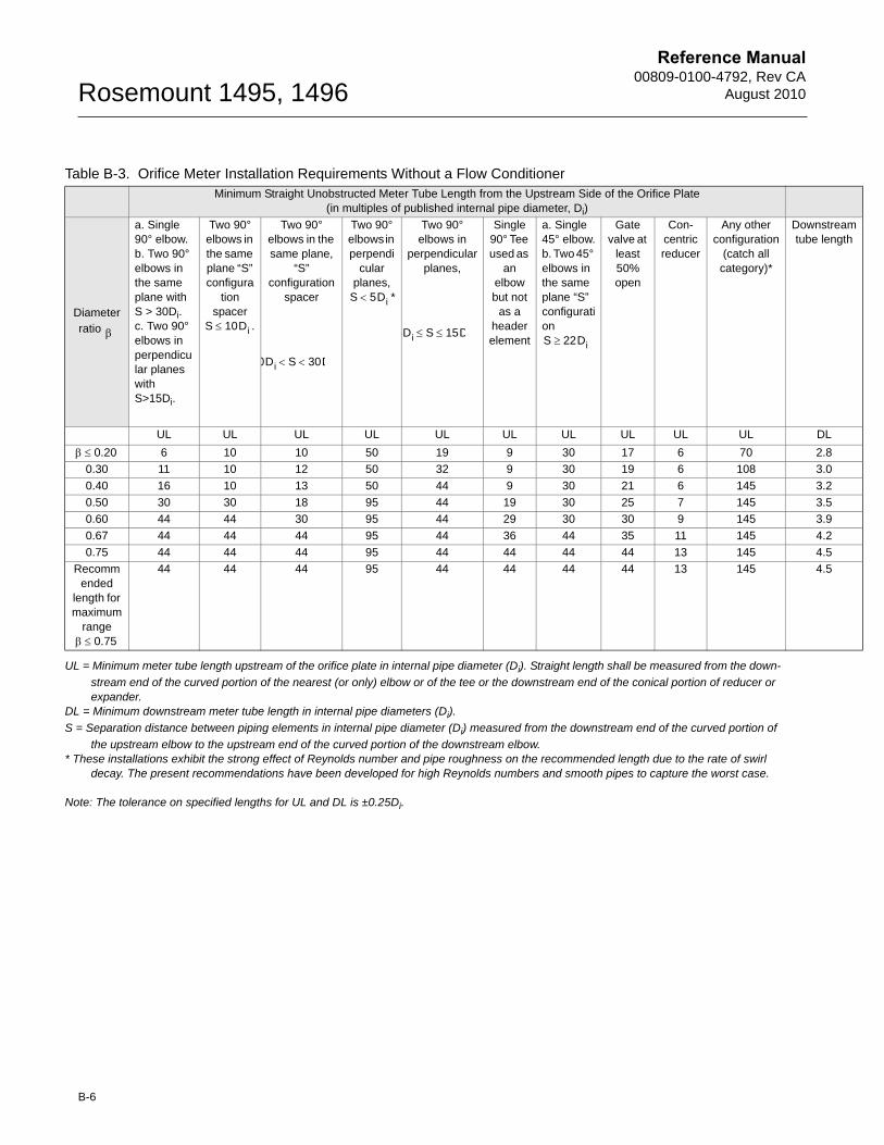
Reference Manual00809-0100-4792, Rev CA
August 2010Rosemount 1495, 1496
stream length
L
.8
.0
.2
.5
.9
.2
.5
.5
UL = Minimum meter tube length upstream of the orifice plate in internal pipe diameter (Di). Straight length shall be measured from the down-
stream end of the curved portion of the nearest (or only) elbow or of the tee or the downstream end of the conical portion of reducer or expander.
DL = Minimum downstream meter tube length in internal pipe diameters (Di).
S = Separation distance between piping elements in internal pipe diameter (Di) measured from the downstream end of the curved portion of
the upstream elbow to the upstream end of the curved portion of the downstream elbow.* These installations exhibit the strong effect of Reynolds number and pipe roughness on the recommended length due to the rate of swirl
decay. The present recommendations have been developed for high Reynolds numbers and smooth pipes to capture the worst case.
Note: The tolerance on specified lengths for UL and DL is ±0.25Di.
Table B-3. Orifice Meter Installation Requirements Without a Flow ConditionerMinimum Straight Unobstructed Meter Tube Length from the Upstream Side of the Orifice Plate
(in multiples of published internal pipe diameter, Di)
Diameter ratio
a. Single 90° elbow.b. Two 90° elbows in the same plane with S > 30Di. c. Two 90° elbows in perpendicular planes with S>15Di.
Two 90° elbows in the same plane “S” configura
tion spacer
.
Two 90° elbows in the same plane,
“S” configuration
spacer
Two 90° elbows in perpendi
cular planes,
*
Two 90° elbows in
perpendicular planes,
Single 90° Tee used as
an elbow but not
as a header element
a. Single 45° elbow.b. Two 45° elbows in the same plane “S” configuration
Gate valve at
least 50% open
Con-centric reducer
Any other configuration
(catch all category)*
Downtube
UL UL UL UL UL UL UL UL UL UL D
6 10 10 50 19 9 30 17 6 70 2
0.30 11 10 12 50 32 9 30 19 6 108 3
0.40 16 10 13 50 44 9 30 21 6 145 3
0.50 30 30 18 95 44 19 30 25 7 145 3
0.60 44 44 30 95 44 29 30 30 9 145 3
0.67 44 44 44 95 44 36 44 35 11 145 4
0.75 44 44 44 95 44 44 44 44 13 145 4
Recommended
length for maximum
range
44 44 44 95 44 44 44 44 13 145 4
S 10Di
0Di S 30D
S 5Di
5Di S 15D S 22Di
0.20
0.75
B-6
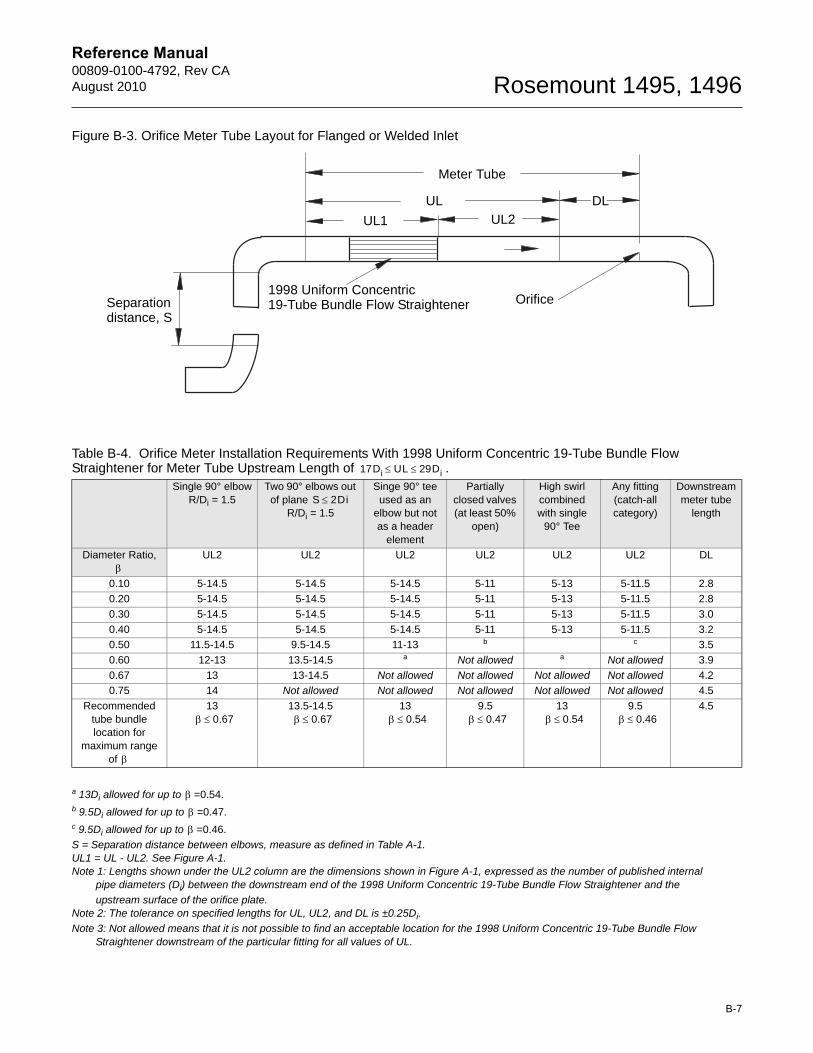
Reference Manual00809-0100-4792, Rev CAAugust 2010 Rosemount 1495, 1496
Figure B-3. Orifice Meter Tube Layout for Flanged or Welded Inlet
a 13Di allowed for up to =0.54.b 9.5Di allowed for up to =0.47.c 9.5Di allowed for up to =0.46.
S = Separation distance between elbows, measure as defined in Table A-1.UL1 = UL - UL2. See Figure A-1.Note 1: Lengths shown under the UL2 column are the dimensions shown in Figure A-1, expressed as the number of published internal
pipe diameters (Di) between the downstream end of the 1998 Uniform Concentric 19-Tube Bundle Flow Straightener and the
upstream surface of the orifice plate.Note 2: The tolerance on specified lengths for UL, UL2, and DL is ±0.25Di.
Note 3: Not allowed means that it is not possible to find an acceptable location for the 1998 Uniform Concentric 19-Tube Bundle Flow Straightener downstream of the particular fitting for all values of UL.
Table B-4. Orifice Meter Installation Requirements With 1998 Uniform Concentric 19-Tube Bundle Flow Straightener for Meter Tube Upstream Length of .
Single 90° elbowR/Di = 1.5
Two 90° elbows out of plane
R/Di = 1.5
Singe 90° tee used as an
elbow but not as a header
element
Partially closed valves (at least 50%
open)
High swirl combined with single
90° Tee
Any fitting (catch-all category)
Downstream meter tube
length
Diameter Ratio, UL2 UL2 UL2 UL2 UL2 UL2 DL
0.10 5-14.5 5-14.5 5-14.5 5-11 5-13 5-11.5 2.8
0.20 5-14.5 5-14.5 5-14.5 5-11 5-13 5-11.5 2.8
0.30 5-14.5 5-14.5 5-14.5 5-11 5-13 5-11.5 3.0
0.40 5-14.5 5-14.5 5-14.5 5-11 5-13 5-11.5 3.2
0.50 11.5-14.5 9.5-14.5 11-13 b c 3.5
0.60 12-13 13.5-14.5 a Not allowed a Not allowed 3.9
0.67 13 13-14.5 Not allowed Not allowed Not allowed Not allowed 4.2
0.75 14 Not allowed Not allowed Not allowed Not allowed Not allowed 4.5
Recommended tube bundle location for
maximum range of
13 13.5-14.5 13 9.5 13 9.5 4.5
Meter Tube
UL DL
UL1 UL2
Orifice1998 Uniform Concentric19-Tube Bundle Flow StraightenerSeparation
distance, S
17Di UL 29Di
S 2Di
0.67 0.67 0.54 0.47 0.54 0.46
B-7
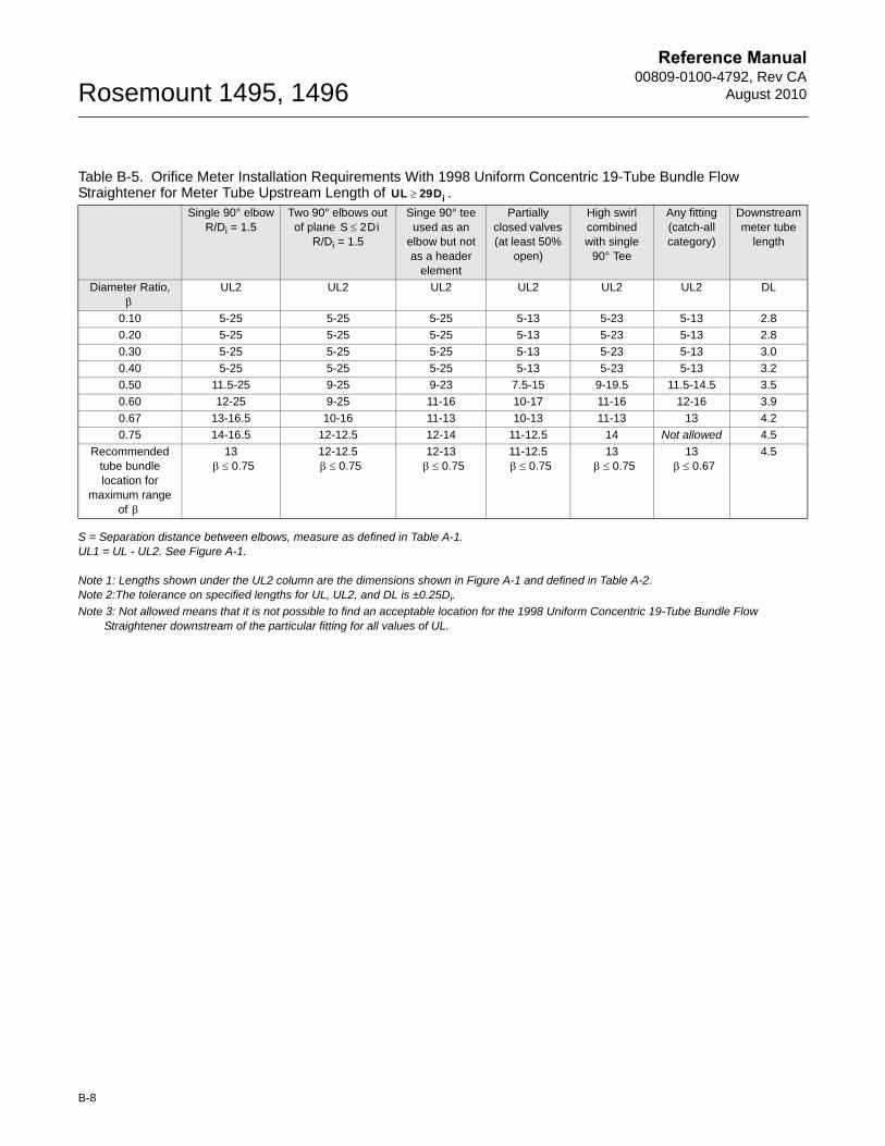
Reference Manual00809-0100-4792, Rev CA
August 2010Rosemount 1495, 1496
S = Separation distance between elbows, measure as defined in Table A-1.UL1 = UL - UL2. See Figure A-1.
Note 1: Lengths shown under the UL2 column are the dimensions shown in Figure A-1 and defined in Table A-2.Note 2:The tolerance on specified lengths for UL, UL2, and DL is ±0.25Di.
Note 3: Not allowed means that it is not possible to find an acceptable location for the 1998 Uniform Concentric 19-Tube Bundle Flow Straightener downstream of the particular fitting for all values of UL.
Table B-5. Orifice Meter Installation Requirements With 1998 Uniform Concentric 19-Tube Bundle Flow Straightener for Meter Tube Upstream Length of .
Single 90° elbowR/Di = 1.5
Two 90° elbows out of plane
R/Di = 1.5
Singe 90° tee used as an
elbow but not as a header
element
Partially closed valves (at least 50%
open)
High swirl combined with single
90° Tee
Any fitting (catch-all category)
Downstream meter tube
length
Diameter Ratio, UL2 UL2 UL2 UL2 UL2 UL2 DL
0.10 5-25 5-25 5-25 5-13 5-23 5-13 2.8
0.20 5-25 5-25 5-25 5-13 5-23 5-13 2.8
0.30 5-25 5-25 5-25 5-13 5-23 5-13 3.0
0.40 5-25 5-25 5-25 5-13 5-23 5-13 3.2
0.50 11.5-25 9-25 9-23 7.5-15 9-19.5 11.5-14.5 3.5
0.60 12-25 9-25 11-16 10-17 11-16 12-16 3.9
0.67 13-16.5 10-16 11-13 10-13 11-13 13 4.2
0.75 14-16.5 12-12.5 12-14 11-12.5 14 Not allowed 4.5
Recommended tube bundle location for
maximum range of
13 12-12.5 12-13 11-12.5 13 13 4.5
UL 29Di
S 2Di
0.75 0.75 0.75 0.75 0.75 0.67
B-8
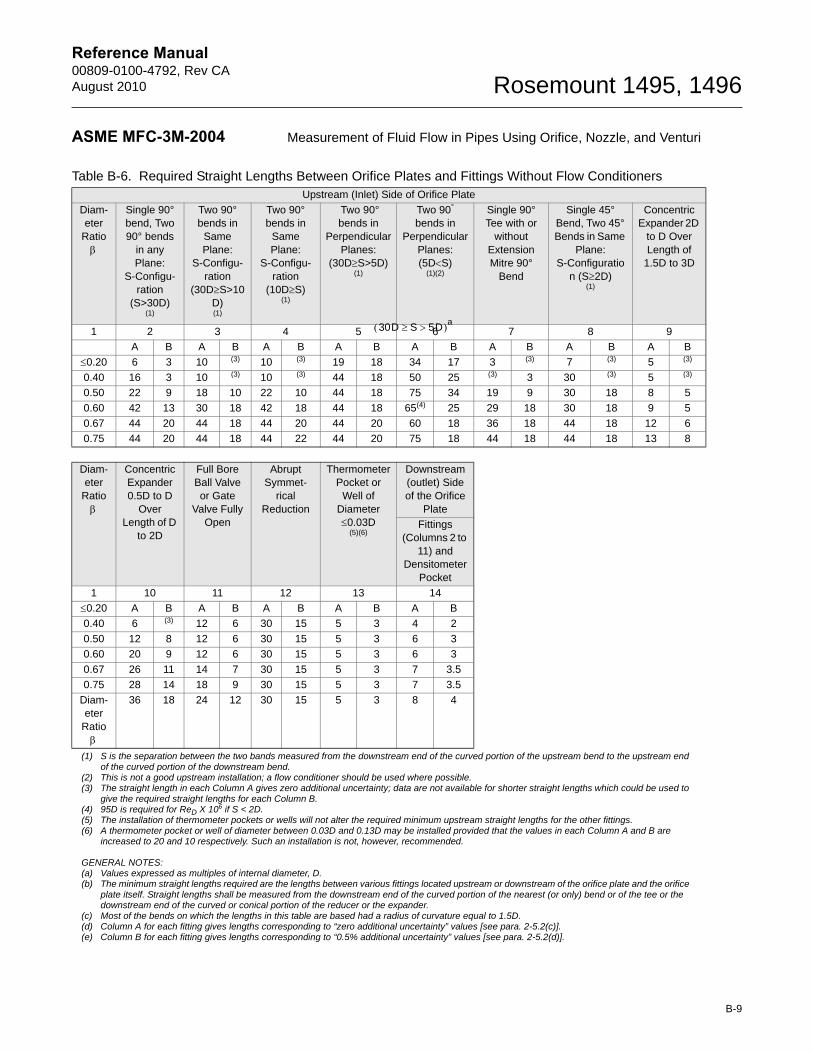
Reference Manual00809-0100-4792, Rev CAAugust 2010 Rosemount 1495, 1496
B-9
ASME MFC-3M-2004 Measurement of Fluid Flow in Pipes Using Orifice, Nozzle, and Venturi
Table B-6. Required Straight Lengths Between Orifice Plates and Fittings Without Flow ConditionersUpstream (Inlet) Side of Orifice Plate
Diam-eter
Ratio
Single 90° bend, Two 90° bends
in any Plane:
S-Configu-ration
(S>30D)(1)
Two 90° bends in
Same Plane:
S-Configu-ration
(30DS>10D)(1)
Two 90° bends in
Same Plane:
S-Configu-ration
(10DS)(1)
Two 90° bends in
Perpendicular Planes:
(30DS>5D)(1)
Two 90° bends in
Perpendicular Planes:(5DS)
(1)(2)
Single 90° Tee with or
without Extension Mitre 90°
Bend
Single 45° Bend, Two 45° Bends in Same
Plane: S-Configuratio
n (S2D)(1)
Concentric Expander 2D
to D Over Length of
1.5D to 3D
1 2 3 4 5 6 7 8 9
A B A B A B A B A B A B A B A B
0.20 6 3 10 (3) 10 (3) 19 18 34 17 3 (3) 7 (3) 5 (3)
0.40 16 3 10 (3) 10 (3) 44 18 50 25 (3) 3 30 (3) 5 (3)
0.50 22 9 18 10 22 10 44 18 75 34 19 9 30 18 8 5
0.60 42 13 30 18 42 18 44 18 65(4) 25 29 18 30 18 9 5
0.67 44 20 44 18 44 20 44 20 60 18 36 18 44 18 12 6
0.75 44 20 44 18 44 22 44 20 75 18 44 18 44 18 13 8
Diam-eter
Ratio
Concentric Expander 0.5D to D
Over Length of D
to 2D
Full Bore Ball Valve or Gate
Valve Fully Open
Abrupt Symmet-
rical Reduction
Thermometer Pocket or
Well of Diameter 0.03D
(5)(6)
Downstream (outlet) Side of the Orifice
Plate
Fittings (Columns 2 to
11) and Densitometer
1 10 11 12 13 14
0.20 A B A B A B A B A B
0.40 6 (3) 12 6 30 15 5 3 4 2
0.50 12 8 12 6 30 15 5 3 6 3
0.60 20 9 12 6 30 15 5 3 6 3
0.67 26 11 14 7 30 15 5 3 7 3.5
0.75 28 14 18 9 30 15 5 3 7 3.5
Diam-eter
Ratio
36 18 24 12 30 15 5 3 8 4
(1) S is the separation between the two bands measured from the downstream end of the curved portion of the upstream bend to the upstream end of the curved portion of the downstream bend.
(2) This is not a good upstream installation; a flow conditioner should be used where possible.(3) The straight length in each Column A gives zero additional uncertainty; data are not available for shorter straight lengths which could be used to
give the required straight lengths for each Column B.(4) 95D is required for ReD X 106 if S < 2D.(5) The installation of thermometer pockets or wells will not alter the required minimum upstream straight lengths for the other fittings.(6) A thermometer pocket or well of diameter between 0.03D and 0.13D may be installed provided that the values in each Column A and B are
increased to 20 and 10 respectively. Such an installation is not, however, recommended.
GENERAL NOTES:(a) Values expressed as multiples of internal diameter, D.(b) The minimum straight lengths required are the lengths between various fittings located upstream or downstream of the orifice plate and the orifice
plate itself. Straight lengths shall be measured from the downstream end of the curved portion of the nearest (or only) bend or of the tee or the downstream end of the curved or conical portion of the reducer or the expander.
(c) Most of the bends on which the lengths in this table are based had a radius of curvature equal to 1.5D.(d) Column A for each fitting gives lengths corresponding to “zero additional uncertainty” values [see para. 2-5.2(c)].(e) Column B for each fitting gives lengths corresponding to “0.5% additional uncertainty” values [see para. 2-5.2(d)].
30D S 5D a
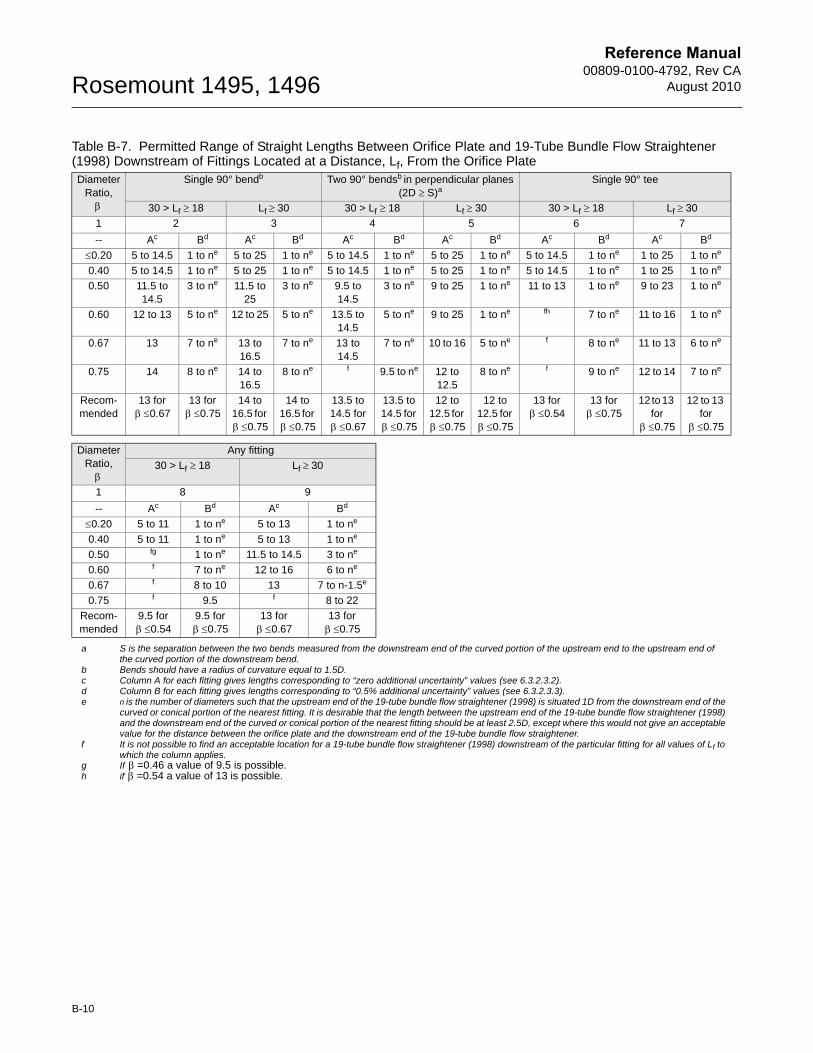
Reference Manual00809-0100-4792, Rev CA
August 2010Rosemount 1495, 1496
a S is the separation between the two bends measured from the downstream end of the curved portion of the upstream end to the upstream end ofthe curved portion of the downstream bend.
b Bends should have a radius of curvature equal to 1.5D.c Column A for each fitting gives lengths corresponding to “zero additional uncertainty” values (see 6.3.2.3.2).d Column B for each fitting gives lengths corresponding to “0.5% additional uncertainty” values (see 6.3.2.3.3).e n is the number of diameters such that the upstream end of the 19-tube bundle flow straightener (1998) is situated 1D from the downstream end of the
curved or conical portion of the nearest fitting. It is desirable that the length between the upstream end of the 19-tube bundle flow straightener (1998) and the downstream end of the curved or conical portion of the nearest fitting should be at least 2.5D, except where this would not give an acceptable value for the distance between the orifice plate and the downstream end of the 19-tube bundle flow straightener.
f It is not possible to find an acceptable location for a 19-tube bundle flow straightener (1998) downstream of the particular fitting for all values of Lf to which the column applies.
g If =0.46 a value of 9.5 is possible.h if =0.54 a value of 13 is possible.
Table B-7. Permitted Range of Straight Lengths Between Orifice Plate and 19-Tube Bundle Flow Straightener (1998) Downstream of Fittings Located at a Distance, Lf, From the Orifice PlateDiameter
Ratio,Single 90° bendb Two 90° bendsb in perpendicular planes
(2D S)aSingle 90° tee
30 > Lf 18 Lf 30 30 > Lf 18 Lf 30 30 > Lf 18 Lf 30
1 2 3 4 5 6 7
-- Ac Bd Ac Bd Ac Bd Ac Bd Ac Bd Ac Bd
0.20 5 to 14.5 1 to ne 5 to 25 1 to ne 5 to 14.5 1 to ne 5 to 25 1 to ne 5 to 14.5 1 to ne 1 to 25 1 to ne
0.40 5 to 14.5 1 to ne 5 to 25 1 to ne 5 to 14.5 1 to ne 5 to 25 1 to ne 5 to 14.5 1 to ne 1 to 25 1 to ne
0.50 11.5 to 14.5
3 to ne 11.5 to 25
3 to ne 9.5 to 14.5
3 to ne 9 to 25 1 to ne 11 to 13 1 to ne 9 to 23 1 to ne
0.60 12 to 13 5 to ne 12 to 25 5 to ne 13.5 to 14.5
5 to ne 9 to 25 1 to ne fh 7 to ne 11 to 16 1 to ne
0.67 13 7 to ne 13 to 16.5
7 to ne 13 to 14.5
7 to ne 10 to 16 5 to ne f 8 to ne 11 to 13 6 to ne
0.75 14 8 to ne 14 to 16.5
8 to ne f 9.5 to ne 12 to 12.5
8 to ne f 9 to ne 12 to 14 7 to ne
Recom-mended
13 for 0.67
13 for 0.75
14 to 16.5 for 0.75
14 to 16.5 for 0.75
13.5 to 14.5 for 0.67
13.5 to 14.5 for 0.75
12 to 12.5 for 0.75
12 to 12.5 for 0.75
13 for 0.54
13 for 0.75
12 to 13 for 0.75
12 to 13 for 0.75
Diameter Ratio,
Any fitting
30 > Lf 18 Lf 30
1 8 9
-- Ac Bd Ac Bd
0.20 5 to 11 1 to ne 5 to 13 1 to ne
0.40 5 to 11 1 to ne 5 to 13 1 to ne
0.50 fg 1 to ne 11.5 to 14.5 3 to ne
0.60 f 7 to ne 12 to 16 6 to ne
0.67 f 8 to 10 13 7 to n-1.5e
0.75 f 9.5 f 8 to 22
Recom-mended
9.5 for 0.54
9.5 for 0.75
13 for 0.67
13 for 0.75
B-10
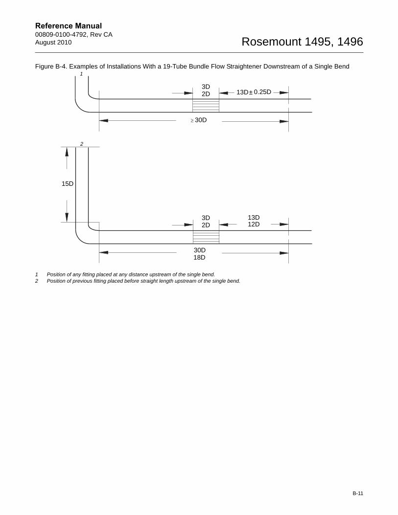
Reference Manual00809-0100-4792, Rev CAAugust 2010 Rosemount 1495, 1496
Figure B-4. Examples of Installations With a 19-Tube Bundle Flow Straightener Downstream of a Single Bend
1 Position of any fitting placed at any distance upstream of the single bend.2 Position of previous fitting placed before straight length upstream of the single bend.
3D2D 13D± 0.25D
30D
3D2D
13D12D
30D18D
15D
1
2
B-11
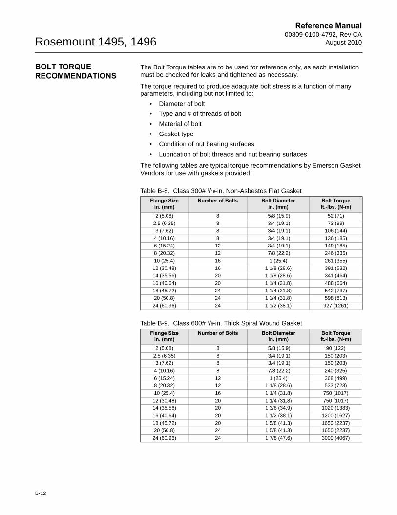
Reference Manual00809-0100-4792, Rev CA
August 2010Rosemount 1495, 1496
BOLT TORQUE RECOMMENDATIONS
The Bolt Torque tables are to be used for reference only, as each installation must be checked for leaks and tightened as necessary.
The torque required to produce adaquate bolt stress is a function of many parameters, including but not limited to:
• Diameter of bolt
• Type and # of threads of bolt
• Material of bolt
• Gasket type
• Condition of nut bearing surfaces
• Lubrication of bolt threads and nut bearing surfaces
The following tables are typical torque recommendations by Emerson Gasket Vendors for use with gaskets provided:
Table B-8. Class 300# 1/16-in. Non-Asbestos Flat Gasket
Flange Sizein. (mm)
Number of Bolts Bolt Diameterin. (mm)
Bolt Torqueft.-lbs. (N-m)
2 (5.08) 8 5/8 (15.9) 52 (71)
2.5 (6.35) 8 3/4 (19.1) 73 (99)
3 (7.62) 8 3/4 (19.1) 106 (144)
4 (10.16) 8 3/4 (19.1) 136 (185)
6 (15.24) 12 3/4 (19.1) 149 (185)
8 (20.32) 12 7/8 (22.2) 246 (335)
10 (25.4) 16 1 (25.4) 261 (355)
12 (30.48) 16 1 1/8 (28.6) 391 (532)
14 (35.56) 20 1 1/8 (28.6) 341 (464)
16 (40.64) 20 1 1/4 (31.8) 488 (664)
18 (45.72) 24 1 1/4 (31.8) 542 (737)
20 (50.8) 24 1 1/4 (31.8) 598 (813)
24 (60.96) 24 1 1/2 (38.1) 927 (1261)
Table B-9. Class 600# 1/8-in. Thick Spiral Wound Gasket
Flange Sizein. (mm)
Number of Bolts Bolt Diameterin. (mm)
Bolt Torqueft.-lbs. (N-m)
2 (5.08) 8 5/8 (15.9) 90 (122)
2.5 (6.35) 8 3/4 (19.1) 150 (203)
3 (7.62) 8 3/4 (19.1) 150 (203)
4 (10.16) 8 7/8 (22.2) 240 (325)
6 (15.24) 12 1 (25.4) 368 (499)
8 (20.32) 12 1 1/8 (28.6) 533 (723)
10 (25.4) 16 1 1/4 (31.8) 750 (1017)
12 (30.48) 20 1 1/4 (31.8) 750 (1017)
14 (35.56) 20 1 3/8 (34.9) 1020 (1383)
16 (40.64) 20 1 1/2 (38.1) 1200 (1627)
18 (45.72) 20 1 5/8 (41.3) 1650 (2237)
20 (50.8) 24 1 5/8 (41.3) 1650 (2237)
24 (60.96) 24 1 7/8 (47.6) 3000 (4067)
B-12
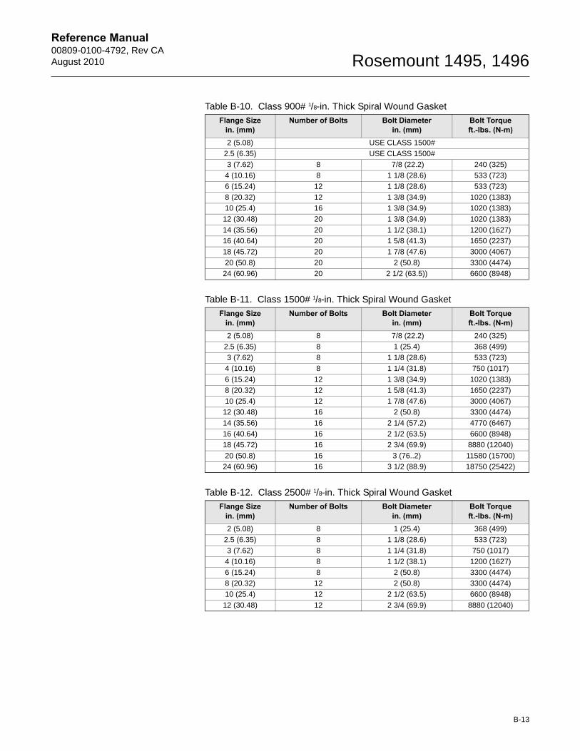
Reference Manual00809-0100-4792, Rev CAAugust 2010 Rosemount 1495, 1496
Table B-10. Class 900# 1/8-in. Thick Spiral Wound Gasket
Flange Sizein. (mm)
Number of Bolts Bolt Diameterin. (mm)
Bolt Torqueft.-lbs. (N-m)
2 (5.08) USE CLASS 1500#
2.5 (6.35) USE CLASS 1500#
3 (7.62) 8 7/8 (22.2) 240 (325)
4 (10.16) 8 1 1/8 (28.6) 533 (723)
6 (15.24) 12 1 1/8 (28.6) 533 (723)
8 (20.32) 12 1 3/8 (34.9) 1020 (1383)
10 (25.4) 16 1 3/8 (34.9) 1020 (1383)
12 (30.48) 20 1 3/8 (34.9) 1020 (1383)
14 (35.56) 20 1 1/2 (38.1) 1200 (1627)
16 (40.64) 20 1 5/8 (41.3) 1650 (2237)
18 (45.72) 20 1 7/8 (47.6) 3000 (4067)
20 (50.8) 20 2 (50.8) 3300 (4474)
24 (60.96) 20 2 1/2 (63.5)) 6600 (8948)
Table B-11. Class 1500# 1/8-in. Thick Spiral Wound Gasket
Flange Sizein. (mm)
Number of Bolts Bolt Diameterin. (mm)
Bolt Torqueft.-lbs. (N-m)
2 (5.08) 8 7/8 (22.2) 240 (325)
2.5 (6.35) 8 1 (25.4) 368 (499)
3 (7.62) 8 1 1/8 (28.6) 533 (723)
4 (10.16) 8 1 1/4 (31.8) 750 (1017)
6 (15.24) 12 1 3/8 (34.9) 1020 (1383)
8 (20.32) 12 1 5/8 (41.3) 1650 (2237)
10 (25.4) 12 1 7/8 (47.6) 3000 (4067)
12 (30.48) 16 2 (50.8) 3300 (4474)
14 (35.56) 16 2 1/4 (57.2) 4770 (6467)
16 (40.64) 16 2 1/2 (63.5) 6600 (8948)
18 (45.72) 16 2 3/4 (69.9) 8880 (12040)
20 (50.8) 16 3 (76..2) 11580 (15700)
24 (60.96) 16 3 1/2 (88.9) 18750 (25422)
Table B-12. Class 2500# 1/8-in. Thick Spiral Wound Gasket
Flange Sizein. (mm)
Number of Bolts Bolt Diameterin. (mm)
Bolt Torqueft.-lbs. (N-m)
2 (5.08) 8 1 (25.4) 368 (499)
2.5 (6.35) 8 1 1/8 (28.6) 533 (723)
3 (7.62) 8 1 1/4 (31.8) 750 (1017)
4 (10.16) 8 1 1/2 (38.1) 1200 (1627)
6 (15.24) 8 2 (50.8) 3300 (4474)
8 (20.32) 12 2 (50.8) 3300 (4474)
10 (25.4) 12 2 1/2 (63.5) 6600 (8948)
12 (30.48) 12 2 3/4 (69.9) 8880 (12040)
B-13

Reference Manual00809-0100-4792, Rev CA
August 2010Rosemount 1495, 1496
B-14
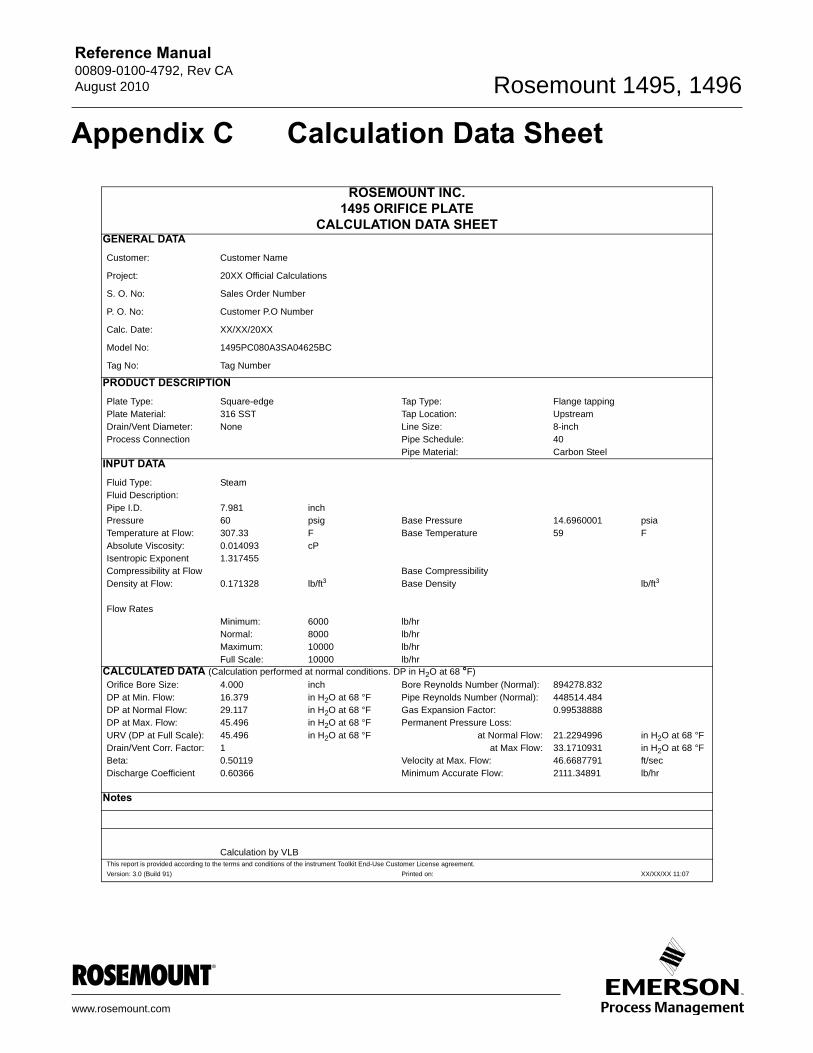
Reference Manual 00809-0100-4792, Rev CAAugust 2010 Rosemount 1495, 1496
Appendix C Calculation Data Sheet
ROSEMOUNT INC.1495 ORIFICE PLATE
CALCULATION DATA SHEETGENERAL DATACustomer: Customer Name
Project: 20XX Official Calculations
S. O. No: Sales Order Number
P. O. No: Customer P.O Number
Calc. Date: XX/XX/20XX
Model No: 1495PC080A3SA04625BC
Tag No: Tag Number
PRODUCT DESCRIPTIONPlate Type: Square-edge Tap Type: Flange tappingPlate Material: 316 SST Tap Location: UpstreamDrain/Vent Diameter: None Line Size: 8-inchProcess Connection Pipe Schedule: 40
Pipe Material: Carbon SteelINPUT DATA
Fluid Type: SteamFluid Description:Pipe I.D. 7.981 inchPressure 60 psig Base Pressure 14.6960001 psiaTemperature at Flow: 307.33 F Base Temperature 59 FAbsolute Viscosity: 0.014093 cPIsentropic Exponent 1.317455Compressibility at Flow Base CompressibilityDensity at Flow: 0.171328 lb/ft3 Base Density lb/ft3
Flow RatesMinimum: 6000 lb/hrNormal: 8000 lb/hrMaximum: 10000 lb/hrFull Scale: 10000 lb/hr
CALCULATED DATA (Calculation performed at normal conditions. DP in H2O at 68 °F)
Orifice Bore Size: 4.000 inch Bore Reynolds Number (Normal): 894278.832DP at Min. Flow: 16.379 in H2O at 68 °F Pipe Reynolds Number (Normal): 448514.484DP at Normal Flow: 29.117 in H2O at 68 °F Gas Expansion Factor: 0.99538888DP at Max. Flow: 45.496 in H2O at 68 °F Permanent Pressure Loss:URV (DP at Full Scale): 45.496 in H2O at 68 °F at Normal Flow: 21.2294996 in H2O at 68 °FDrain/Vent Corr. Factor: 1 at Max Flow: 33.1710931 in H2O at 68 °FBeta: 0.50119 Velocity at Max. Flow: 46.6687791 ft/secDischarge Coefficient 0.60366 Minimum Accurate Flow: 2111.34891 lb/hr
Notes
Calculation by VLBThis report is provided according to the terms and conditions of the instrument Toolkit End-Use Customer License agreement.
Version: 3.0 (Build 91) Printed on: XX/XX/XX 11:07
www.rosemount.com

Reference Manual00809-0100-4792, Rev CA
August 2010Rosemount 1495, 1496
C-2
NOTES


Reference Manual00809-0100-4792, Rev CA
August 2010
00809-0100-4792 Rev CA, 8/10
Standard Terms and Conditions of Sale can be found at www.rosemount.com\terms_of_saleThe Emerson logo is a trademark and service mark of Emerson Electric Co.Rosemount and the Rosemount logotype are registered trademarks of Rosemount Inc.PlantWeb is a registered trademark of one of the Emerson Process Management group of companies.All other marks are the property of their respective owners.
© 2010 Rosemount Inc. All rights reserved.
Emerson Process ManagementRosemount Measurement8200 Market BoulevardChanhassen, MN 55317 USAT (U.S.) 1-800-999-9307T (International) (952) 906-8888F (952) 949-7001
www.rosemount.com
Emerson Process ManagementShared Services Ltd.Heath PlaceBognor RegisWest Sussex PO22 9SHEnglandT 44 (1243) 863 121F 44 (1243) 867 554
Emerson Process Management Asia Pacific Private Limited1 Pandan CrescentSingapore 128461T (65) 6777 8211F (65) 6777 [email protected]