INSTALLATION, OPERATION &...
32
INSTALLATION, OPERATION & MAINTENANCE Unit Coolers & Product Coolers
Transcript of INSTALLATION, OPERATION &...

INSTALLATION, OPERATION & MAINTENANCE
Unit Coolers & Product Coolers

TABLE OF CONTENTS
Installation and Operation Mounting Piping Wiring Evacuation DefrostAdditional System Information Refrigerant Piping Effects of Space Infiltration Effects of Unbalance Voltage on Motor Performance Drive (Product Coolers) Adjusting CFM (Product Coolers) ECBlue FansMaintenance TXV Installation and Troubleshooting Warranty AppendixThrow Cone - A SeriesThrow Cone - BOC Series
33444488899910111221232627

3
Unit is designed to be relocated as required if the need arises.
I. MOUNTING
Check equipment for shipping damage. If damage has occurred, a claim should be made with the trans-portation company. The local Century representative should be advised of the nature of the damage.
A. A, BALV, BOC, XBOC, EPIC & PFE SERIES UNIT COOLERS These units are shipped in the upright position. Remove top and sides of crate. Leave unit on skid in shipping position to do necessary electrical work and assemble expansion valve to coil. The shipping skid may be used to support unit while installing.The unit evaporators are designed to be mounted di-rectly to ceiling or suspended by rods. The top of the evaporator must be closed and sealed to the ceiling or suspended to provide sufficient clearance so it is readily accessible for cleaning. Ample space should be allowed at each end for room to adjust expansion valve or service electrical controls if required. Fan side of unit must be kept clear for proper air distri-bution.
After unit is securely fastened in position, shipping legs may be removed from unit.
The Epic series unit coolers are designed to have fan and end panels that are hinged with lift off ability, quick connect fan wiring, and a hinged drain pan. The fan panels make for quick service and cleaning of the coil. The Epic series also offers ECblue fans, refer to ECblue fan section for more details.
B. FH SERIES UNIT COOLERS The FH Series evaporators are shipped in the invert-ed position.
Remove top and sides of crate or box. Leave unit on skid in shipping position to do necessary electrical work and assemble expansion valve to coil. Turn unit to mounting position and remove skid. Take neces-sary precautions not to damage the drain pan.The unit evaporator is designed to be mounted directly to ceiling or suspended by rods. The top of the evaporator must be closed and sealed to the ceiling or suspended to provide sufficient clearance so it is readily accessible for cleaning. Do not mount unit with less than 15 inches between coil face and wall. Ample space should be allowed at each end for room to adjust expansion valve or service electrical controls if required. Fan side of unit must be kept clear for proper air distribution.
C. FV SERIES UNIT COOLERSThe FV Series evaporators are shipped in the invert-ed position.
Remove top and sides of crate. Leave unit on ship-ping skid to do necessary electrical work and as-semble expansion valve to coil. Remove bolts from skid, turn unit to mounting position and place back on skid, taking necessary precautions not to damage unit.
The unit evaporator is designed to be mounted di-rectly to the ceiling or suspended from rods. The top of the evaporator must be closed and sealed to the ceiling or suspended to provide sufficient clearance so it is readily accessible for cleaning. Unit is pitched with the hangers for proper condensate drainage; therefore, unit must be mounted level with the top of the hangers. Unit is a blow-through type with air entering at the bottom and discharging out both sides. Ample space at each end for room to adjust expansion valve or service electrical controls is required. For proper air distribution, both sides and bottom of unit must be kept clear
D. HPC/VPC PRODUCT COOLERSHPC/VPC units are designed for floor and/or sus-
NOTE: Unit must be mounted level for proper condensate draining.
NOTE: Reference unit submittal drawing for service clearances. If not available,
contact factory.
Installation & Operation

4
pended platform mounting, and located within the conditioned space. Install units level, locate so that the inlet and outlet air flow is unobstructed. Position units away from walls a distance equal to the height of the blower section for proper air flow and service. It is very important that the entire unit be installed level to prevent unit distortion and to insure proper condensate drainage.
E. WIBR SERIES UNIT COOLERThese units are shipped in the upright position. Remove top and sides of crate. Leave unit on skid in shipping position to do necessary electrical work and assemble expansion valve to coil. The shipping skid may be used to support unit while installing.The unit evaporators are designed to be mounted di-rectly to ceiling or suspended by rods. The top of the evaporator must be closed and sealed to the ceiling or suspended to provide sufficient clearance so it is readily accessible for cleaning. Ample space should be allowed at each end for room to adjust expansion valve or service electrical controls if required. Fan side of unit must be kept clear for proper air distri-bution.
Drain pan must be adjusted for maximum slope.1. Loosen all drain pan bolts. 2. Raise the end opposite of the drain to the top of adjustment slot. 3. Make sure drain end is at the bottom of the adjustment slot.4. Tighten all drain pan bolts.
II. PIPINGAll Century evaporators are designed for use with remote condensing units. All connecting piping must be installed by qualified personnel in accordance with applicable local and national codes. All piping, traps, risers and line sizes should be in accordance with good piping practices for proper operation.The drain line piping located inside the refriger-ated space should be kept as short as possible and pitched a minimum of 1/2 inch per foot. If room is held below freezing, drain line must be wrapped with heat tape and insulated. Each unit should be individually trapped before connection to a common drain.
III. WIRINGPower wiring must be adequately sized for minimum circuit ampacity and voltage as shown on the name-plate. All internal wiring is completed at the factory. A wiring diagram is furnished with each unit show-ing field connections and internal wiring. Access to internal connections may be made by removing end panel opposite expansion valve end of unit. All power must be turned off before removing any access panels. All wiring should be done in strict ac-cordance with local and national electrical codes.
IV. EVACUATION With refrigerant piping complete and leak tested equipment is ready to evacuate. A quality vacuum pump capable of 350 micron vacuum is necessary for adequate and dependable system evacuation.
VI. DefrostI. GENERAL SET-UPA time clock is used to initiate and terminate a de-frost period. They are used for air, electric, and hot gas defrost systems. All types utilize the same type of initiation where pins on a rotating clock mechani-cally actuate the timer to initiate the defrost period. The pins can be place for any hour of the day or night. There should be at least 4 pins installed for start-up to ensure the coil does not ice over during the commissioning period when doors are open to high temperatures and humidity. Once product is brought into the cooled space, the frost load will have to be monitored in order to determine when the defrost periods should initiate.
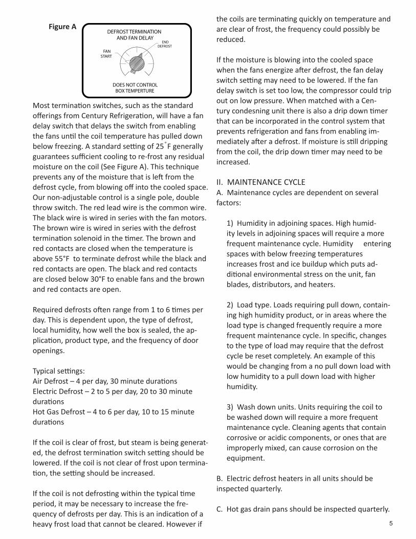
All types of defrost can have a timed termination. However, for electric and hot gas defrost it is general practice to also use a separate termination switch to bring the freezer unit out of defrost sooner. By looking at coil temperature it can be assumed that the coil is clear of frost when it is approximately 50˚F to 60˚F (See Figure A). By terminating when needed, energy consumption can be drastically reduced and problems associated with prolonged heat cycles like steaming can be prevented.
NOTE: Residual moisture in a refrigeration system can cause corrosion, expansion
valve freeze-up and oil sludge.
5
Most termination switches, such as the standard offerings from Century Refrigeration, will have a fan delay switch that delays the switch from enabling the fans until the coil temperature has pulled down below freezing. A standard setting of 25˚F generally guarantees sufficient cooling to re-frost any residual moisture on the coil (See Figure A). This technique prevents any of the moisture that is left from the defrost cycle, from blowing off into the cooled space. Our non-adjustable control is a single pole, double throw switch. The red lead wire is the common wire. The black wire is wired in series with the fan motors. The brown wire is wired in series with the defrost termination solenoid in the timer. The brown and red contacts are closed when the temperature is above 55°F to terminate defrost while the black and red contacts are open. The black and red contacts are closed below 30°F to enable fans and the brown and red contacts are open.
Required defrosts often range from 1 to 6 times per day. This is dependent upon, the type of defrost, local humidity, how well the box is sealed, the ap-plication, product type, and the frequency of door openings.
Typical settings:Air Defrost – 4 per day, 30 minute durationsElectric Defrost – 2 to 5 per day, 20 to 30 minute durationsHot Gas Defrost – 4 to 6 per day, 10 to 15 minute durations
If the coil is clear of frost, but steam is being generat-ed, the defrost termination switch setting should be lowered. If the coil is not clear of frost upon termina-tion, the setting should be increased.
If the coil is not defrosting within the typical time period, it may be necessary to increase the fre-quency of defrosts per day. This is an indication of a heavy frost load that cannot be cleared. However if
the coils are terminating quickly on temperature and are clear of frost, the frequency could possibly be reduced.
If the moisture is blowing into the cooled space when the fans energize after defrost, the fan delay switch setting may need to be lowered. If the fan delay switch is set too low, the compressor could trip out on low pressure. When matched with a Cen-tury condesning unit there is also a drip down timer that can be incorporated in the control system that prevents refrigeration and fans from enabling im-mediately after a defrost. If moisture is still dripping from the coil, the drip down timer may need to be increased.
II. MAINTENANCE CYCLEA. Maintenance cycles are dependent on several factors:
1) Humidity in adjoining spaces. High humid-ity levels in adjoining spaces will require a more frequent maintenance cycle. Humidity entering spaces with below freezing temperatures increases frost and ice buildup which puts ad-ditional environmental stress on the unit, fan blades, distributors, and heaters.
2) Load type. Loads requiring pull down, contain-ing high humidity product, or in areas where the load type is changed frequently require a more frequent maintenance cycle. In specific, changes to the type of load may require that the defrost cycle be reset completely. An example of this would be changing from a no pull down load with low humidity to a pull down load with higher humidity.
3) Wash down units. Units requiring the coil to be washed down will require a more frequent maintenance cycle. Cleaning agents that contain corrosive or acidic components, or ones that are improperly mixed, can cause corrosion on the equipment.
B. Electric defrost heaters in all units should be inspected quarterly.
C. Hot gas drain pans should be inspected quarterly.
FANSTART
ENDDEFROST
DEFROST TERMINATIONAND FAN DELAY
DOES NOT CONTROLBOX TEMPERTURE
Figure A

6
III. Maintenance GuidelinesA. Check and record the evaporator fan and defrost heater (where applicable) circuit volt/amp readings against the baseline that has been established.
B. Electric defrost only: If the readings do not match baseline on the heater circuit the individual heaters should be amped to see which heaters have failed. Once the heater has been identified it should be re-placed. It is recommended to replace 460V unit heat-ers in pairs as they are two 230V heaters in series.
C. Visually check the wiring connections for corro-sion, signs of overheating, or other mechanical issues throughout the defrost heater (if equipped), evapora-tor fan circuits, and control circuits including at the main fuse blocks, contactors, and inside the evapora-tor itself.
D. Check the wiring connections for tightness through-out the circuits.
E. Check the contactors to make sure the contacts are not pitted. Replace if necessary.
F. Check to make sure there are no areas in the evapo-rator where excessive ice is building up. If there is a sheet or ball of ice building on any surface it is consid-ered excessive.
G. Electric defrost only: Check the heaters to ensure that they are secure in their clips and that the heater boot is not damaged. Tighten any loose clips. Replace the heaters if there is damage to the boot.
H. Electric defrost only: Check to ensure that the heaters do not rub against or run into any piping wire bundles, brackets or other sharp or angular items that may cause the heater to rub through and short out.
I. Electric defrost only: Check to ensure that all wiring is situated so that it will not come into contact with heater elements during any stage of the defrost cycle. The heaters can burn through wiring that is allowed to come into direct contact with the sheath.
J. Observe the entire defrost cycle and adjust as nec-essary in order to ensure that defrosting is complete, drip down time is adequate, and that the coil is frosted completely before the fans re-energize. A coil that is properly frosted will have frost over all or the majority of the u-bends on both ends of the coil. If at least 80% of the u-bends are not frosted there may be residual water on the coil and it can be blown into the space when the fans come on.
IV. General Heater Operation: Electric defrost onlyA. When a defrost heater is energized it will expand as it heats.
B. After defrost the heater will cool and shrink back to its original size.
C. The rate of expansion and contraction is affected by the ambient conditions that the heater is subjected to. This expansion and contraction makes it vital to ensure that the heaters do not rub against anything sharp or angular and that they do not expand directly into items that will prevent their natural motion.
V. Common issuesA. The most common indication that there is a prob-lem with defrost is obvious ice buildup on the coil. Site personnel must be taught to report ice buildup as soon as it is observed. Allowing ice to build up excessively will compound any original issues and cause further
Warning! Excessive ice buildup can cause a variety of problems by placing mechanical stress on the coils, heaters, wiring, distributors, valves, and sheet metal components. Ice accumulations should be removed from all surfaces
during the routine maintenance cycle at a minimum. Ice accumulation can crush
tube resulting in refrigeration leaks.
NOTE: On electric defrost units the heat/cool cycle of heaters can increase the speed of corrosion by concentrating
the cleaning agent on the heater when it heats up during the defrost cycle. This
evaporates the water and leaves the chemicals in the cleaning agent as a dried
coating on the heater.

7
damage to heaters, distributors, and eventually to the coil and housing. Remove excessive ice buildup as soon as possible.
B. Electric defrost only: When a heater fails that area is no longer able to defrost properly. Through sub-sequent defrost cycles, frost and then ice will build around the site of the inactive heater. As this ice area builds it will entrap other heaters. When these other heaters become entrapped they can be damaged when they go into defrost. The ice prevents their natural motion during expansion. The heater will build up heat and melt the ice surrounding it over time but damage would also occur during this process. Subsequently, when defrost has ended, the heaters will prematurely freeze in the ice pack which will prevent them from contracting easily. This can cause severe damage to the heater including pulling the heater apart. When these heaters fail the icing and consequently the damage will spread to other areas of the coil. If this is allowed to continue the coil will become encased in ice which can damage or destroy the unit.
C. Electric defrost only: Units equipped with spring type defrost clips help to limit problems due to icing but are not a substitute for correct defrost setup and maintenance. If the defrost does not clear the coil suf-ficiently or if a heater goes out during normal use the resulting ice buildup will eventually encase and trap the spring rendering it ineffective. The clamp hold-ing the heater to the clip and the clip itself must also be properly secured and checked for tightness during maintenance to ensure that the heater does not slide in the clamp.
D. Electric defrost only: If the heaters are exposed to corrosives either by being washed down or by being in a space containing corrosives in the atmosphere the heater sheath can be compromised. Intergranular corrosion leads to signs of cracking and pitting on the sheath. Powdery deposits may develop on the sheath as well as the corrosives are deposited and then dry on the heater or the corrosives leach material out of the heater sheath itself. Heater failures caused by corro-sion normally occur in the coil pack and the heater will show obvious signs of cracking and pitting including having chunks of heater missing. Additional signs of corrosion can be seen on the cabinet, fin, and cop-per tubing. White rust on galvanized components is normal, however red rust indicates that iron is being
leached out of the metal. Oxides on the aluminum fin pack indicate the presence of corrosives in the envi-ronment.
E. Electric defrost only: Short circuits can cause dam-age to heaters. This is identified by striping on the sheath perpendicular to the heater. This can best be explained by saying the heater sheath looks like a hotdog with grill marks on it. The grill marks are where a short circuit has melted part of the coil fin onto the heater sheath. Any heaters showing this pattern should be replaced.F. Electric defrost only: If the hot part of two heat-ers come in contact during defrost they will cause a hotspot which weakens the heater sheath. After the sheath is weakened it will eventually stress fracture and break. This can be identified by a half moon sec-tion of the heater being missing. The internal element of the heater and the heater packing will often be visible.
G. Loose wiring connections can be identified by blis-tered or melted wiring insulation at the terminal block or point of connection. Note that loose connections not only damage the wiring but can also lead to pitting on the contacts at the contactor. If any loose wiring is found also check the contactor associated with that wiring.
H. Power problems can be identified by catastrophic failure of heaters and motors. This often blows heaters apart and can melt the surrounding fin and tubing or can blow through windings in motor. Corner grounded delta wiring configurations can cause catastrophic fail-ures due to the higher than normal voltage to ground. If the site power is corner grounded delta the unit will have to be specially wired and fused for that power configuration. Voltage spikes and dips (brownouts) can damage the heaters and fan motors causing premature failure. If site power is not “clean” or voltage issues are probable the use of phase monitors is suggested. Power issues can burn out the control boards on ECM motors.
I. Hot gas only: If hot gas coils have tubes damaged by ice buildup and those tubes are abandoned that tube section will no longer defrost. This will lead to excessive ice buildup in the associated area. It may be possible to add auxiliary electric heat to rectify this without having to replace the entire coil.

8
Additional System InformationI. REFRIGERANT PIPINGGood equipment performance depends to a large extent on correct refrigerant line sizing. Friction losses, oil return, and piping cost must all be con-sidered in determining the best sizes for discharge, liquid, and suction.
Detailed data in ASHRAE Data Books should be con-sulted for actual conditions found in specific applica-tions.
Century Refrigeration does not warrant the ade-quacy of this data for any particular job, as field and installation conditions are not within our control.
Circuit capacity will be the actual compressor capac-ity at operating conditions. It could be necessary to provide a double suction riser for any circuit having a vertical lift from the evaporator and variable refriger-ant flow (compressor unloading or hot gas bypass back to the suction side of the compressor.)
Equivalent length of lines will be the actual length plus allowance for valves, fittings, etc. On normal air conditioning installations, it can be assumed that the equivalent length will be approximately two times the actual length.
Line configuration requires the actual piping layout to determine valves, elbows, risers, etc. This is also the time to determine if oil traps and dual risers are necessary.
It is also necessary to provide suction line traps if this vertical rise exceeds 10 to 12 feet. A suction line trap is nothing more than an “S” bend which will trap oil and form a seal when the compressor is run-ning in the unloaded condition.All horizontal lines are to slope approximately 1 inch downward per 10 feet in the direction of flow.
A. LIQUID LINEThe liquid line from the receiver to the expansion valve is usually sized for a pressure drop equivalent to (approximately) 1°F. (The liquid line from the condenser to the receiver is usually sized for a liquid velocity of 100 FPM to allow vapor generated in the
receiver to return to the condenser.) Excessive liquid line pressure drops may cause some of the liquid to flash into vapor before entering the expansion valve, reducing system capacity. Liquid lines are not as criti-cal as suction lines as oil will remain in solution with liquid refrigerant.
B. LIQUID LINE SOLENOID PLACEMENTThe liquid line solenoid valve is best placed as close to the expansion valve as possible. When a system pumps down, the liquid refrigerant in the evaporator is mostly evaporated and the refrigerant is pumped to the condenser and receiver where it is stored dur-ing the off cycle. When the liquid line solenoid is placed on the condensing unit, the entire liquid line from the solenoid valve to the expansion valve must also be pumped down. A small problem is that this can lengthen the pump down period. A much larger concern is that the condenser and receiver do not have the storage capacity for this additional refriger-ant. If they are not sufficient in size, they will fill up with liquid until high pressure is built and the com-pressor trips the manual reset high pressure safety. A good practice is to install the liquid line solenoid just outside the room so that maintenance does not have to be performed in the refrigerated space. Most systems can handle long line sets in excess of 50’, but smaller systems should be looked at closely to ensure the condenser and receiver will have suf-ficient storage capacity.
C. SUCTION LINEReduced suction pressure due to excessive suction line pressure drop will reduce the density of the suction gas in a reciprocating (fixed displacement) compressor. This means less weight of refrigerant pumped, resulting in reduced compressor capacity.It is a generally accepted practice to size suction lines for a pressure drop approximately equivalent to 2°F to obtain the optimum compromise between piping cost, oil return, and friction loss.
II. EFFECTS OF SPACE INFILTRATIONRefrigerated spaces are heavily insulated, sealed, and controlled for traffic to prevent heat and moisture gain from outside of the space. When these requirements are not met, the load on the re-

9
frigerating equipment will be higher than designed. In many cases the system will simply run longer than necessary to handle the heat load. Unfortunately, this is an expensive waste of energy. Sometimes, the load exceeds what the equipment was designed to handle and room temperature cannot be met. When this happens, either the excess infiltration must be corrected or additional refrigeration equipment must be added.
Infiltration can be detected by frost build up in the room. It can be a light frost on anything in the room including the walls, doors, ceiling, freezer unit cabi-netry, etc. Infiltration is very obvious when it forms stalactites or stalagmites. The outside humidity levels will have an effect on the amount of frost and ice that accumulates in the room. III. EFFECTS OF UNBALANCED VOLTAGE ON MOTOR PERFORMANCEAlternating current polyphase motors will operate successfully under running conditions at rated load when the voltage unbalance at the motor termi-nals does not exceed 1 percent. Performance will not necessarily be the same as when the motor is operating with an unbalanced voltage at the motor terminals.
A relatively small unbalance in voltage will cause a considerable increase in temperature rise. In the phase with the highest current, the percentage in-crease in temperature rise will be approximately two times the square of the percentage voltage unbal-ance. The increase in losses, and consequently, the increase in average heating of the whole winding will be slightly lower than the winding with the highest current.
If nuisance trip outs or repeated trip outs of a motor are experienced and diagnosis of the motor shows no faults, phase unbalance is a likely cause.To illustrate the severity of this condition, an ap-proximate 3.5 percent voltage unbalance will cause an approximate 25 percent increase in temperature rise.The percent of voltage unbalance is equal to 100 times the maximum voltage deviation from the aver-
age voltage divided by the average voltage.
IV. DRIVE (PRODUCT COOLERS) Check for proper rotation of the blower pulley. Check the amperage of the motor under operating conditions. This should not exceed the nameplate amps shown on the motor serial plate or unit name-plate. After approximately two weeks of operation, the belts will have nearly acquired their permanent stretch. After this interval, the belt tension should be checked again and proper adjustment made. Bearings are self-aligning, ball bearing selected for an average service life in excess of 200,000 hours. Bearings are sealed, and lubricated at the factory. Should additional lubrication be required care must be taken not to damage bearing seals.
V. ADJUSTING CFM (PRODUCT COOL-ERS) All HPC/VPC units have adjustable belt drives. Initial fan speed is established at the factory, based on specifications furnished with the order. Should it be necessary to change fan speed in the field, care should be taken not to overload the motor.
NOTE: All units have bypass air capability. This is to limit the coil face velocity to 550 FPM for wet coil applications and 700 FPM
for dry coil applications.

10
VI. ECBlue FansUpon arrival check the fans for low vibration and quiet operation. Transportation damage (e.g. cracks, dents, or damaged electrical cables) or improper use could potentially lead to failure. Fans should also be checked for the direction of rotation. An arrow indicating the direction of rotation is located on the fan blade, impeller base plate, or on the fan housing.Make sure fasteners are tightened to the specified torque, listed in Table 1. For troubleshooting refer to the connection diagram, Diagram 1, and faults list, Table 2.
WARNING: Before servicing it is recommended to wait at least three minutes after main supply has been switched off before opening
the controller housing.
Table 1
Diagram 2
Table 2
11
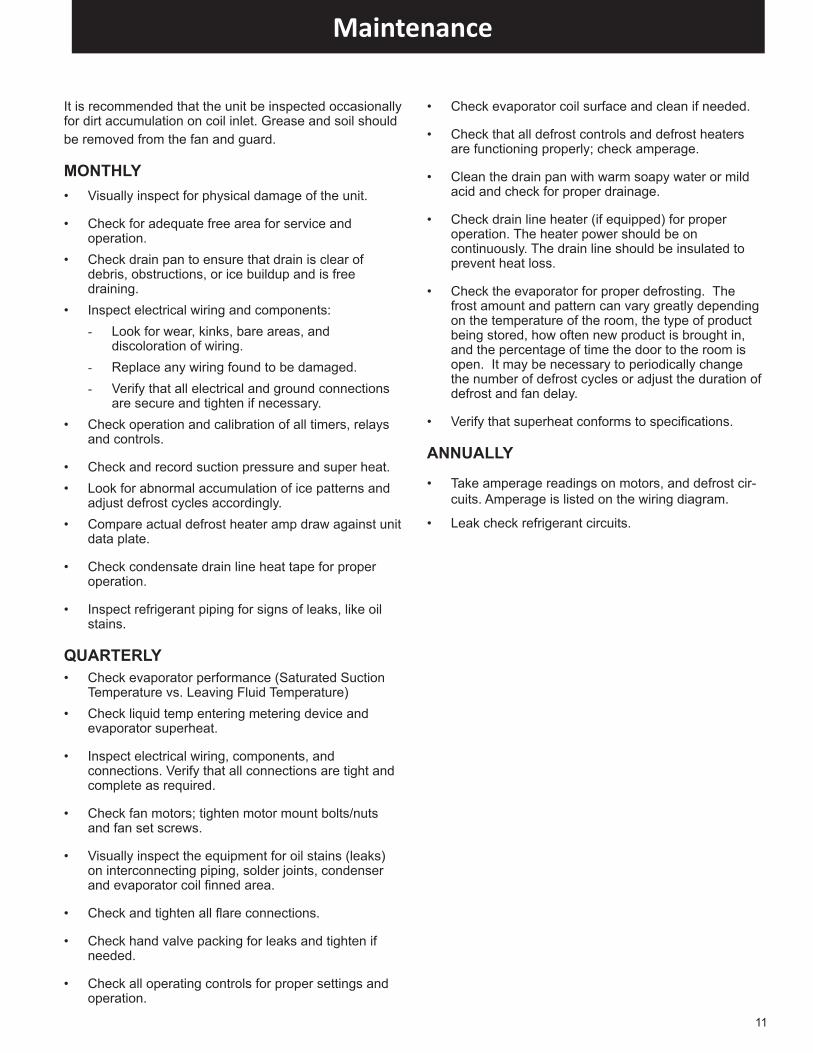
It is recommended that the unit be inspected occasionally for dirt accumulation on coil inlet. Grease and soil should be removed from the fan and guard.
MONTHLY• Visually inspect for physical damage of the unit.
• Check for adequate free area for service and operation.
• Check drain pan to ensure that drain is clear of debris, obstructions, or ice buildup and is free draining.
• Inspect electrical wiring and components: - Look for wear, kinks, bare areas, and
discoloration of wiring. - Replace any wiring found to be damaged. - Verify that all electrical and ground connections
are secure and tighten if necessary. • Check operation and calibration of all timers, relays
and controls.
• Check and record suction pressure and super heat.• Look for abnormal accumulation of ice patterns and
adjust defrost cycles accordingly.• Compare actual defrost heater amp draw against unit
data plate.
• Check condensate drain line heat tape for proper operation.
• Inspect refrigerant piping for signs of leaks, like oil stains.
QUARTERLY• Check evaporator performance (Saturated Suction
Temperature vs. Leaving Fluid Temperature)• Check liquid temp entering metering device and
evaporator superheat.
• Inspect electrical wiring, components, and connections. Verify that all connections are tight and complete as required.
• Check fan motors; tighten motor mount bolts/nuts and fan set screws.
• Visually inspect the equipment for oil stains (leaks) on interconnecting piping, solder joints, condenser and evaporator coil finned area.
• Check and tighten all flare connections.
• Check hand valve packing for leaks and tighten if needed.
• Check all operating controls for proper settings and operation.
• Check evaporator coil surface and clean if needed.
• Check that all defrost controls and defrost heaters are functioning properly; check amperage.
• Clean the drain pan with warm soapy water or mild acid and check for proper drainage.
• Check drain line heater (if equipped) for proper operation. The heater power should be on continuously. The drain line should be insulated to prevent heat loss.
• Check the evaporator for proper defrosting. The frost amount and pattern can vary greatly depending on the temperature of the room, the type of product being stored, how often new product is brought in, and the percentage of time the door to the room is open. It may be necessary to periodically change the number of defrost cycles or adjust the duration of defrost and fan delay.
• Verify that superheat conforms to specifications.
ANNUALLY
• Take amperage readings on motors, and defrost cir-cuits. Amperage is listed on the wiring diagram.
• Leak check refrigerant circuits.
Maintenance
12
InstallationFor peak performance, it is important to select a Sporlan Thermostatic Expansion Valve (TEV) with correct capacity, selective charge, external or internal equalizer, etc. See Bulletins 10-9 and 10-10 for complete application information. Equally important is the proper installation, which can determine the success or failure of the entire system.
Valve LocationTEVs may be mounted in any position, but they should be installed as close to the evaporator as possible. If a refrigerant distributor is used with the expansion valve, best performance is obtained if the distrib-utor is mounted directly to the valve outlet. If the distributor cannot be mounted directly to the valve outlet, the distance between the valve outlet and distributor should not exceed 24 inches or refrigerant distribu-tion problems may occur. Also, the tube connecting the valve outlet and distributor can be sized smaller to maintain refrigerant velocity and better distribution. Elbows located between the expansion valve and distributor will hinder proper distribution and are not recommended.
Best distribution is usually obtained if the expansion valve feeds vertically up or down into the distributor. System manufacturers, however, have successfully applied distribu-tors in other orientations. See Bulletin 20-10 for application and selection information on refrigerant distributors.
While not always convenient or possible, valve Types BI, F, FB, and O are easier to service if mounted in a vertical and upright position. If mounted in a horizontal position, the internal parts must be carefully reassembled to prevent damage to them. Also, some consideration should be taken in mounting larger sized expansion valves. They must be adequately supported since system vibration and the weight of the valve may cause valve connections to fracture.
If a hand valve is located on the outlet side of the TEV it should have a full sized port. No restrictions should appear between the TEV and the evaporator, except a refrig-erant distributor if one is used.
Sporlan TEVs having Selective Charges C, Z, L, or X may be installed and operated in most locations. The amount of thermostatic charge and the bulb size are such that the bulb retains control despite a colder valve body or diaphragm case. The exception is when the element is subjected to sub-zero temperatures for extended periods of time
during an off-cycle. In this case, start-up may be prolonged until the bulb and element are warmed sufficiently to open the valve.
To minimize the possibility of charge migration, the Sporlan MOP type charges (CP series and ZP series) and GA series should be installed so the diaphragm case is warmer than the bulb. Special non-condens-able charges without MOP and double diaphragm hydraulic elements with MOP are available for system manufacturers to overcome this potential problem.
Occasionally, TEVs are located in corrosive atmospheric conditions that can damage the valve and/or the element assembly. Due to this possibility, the valve must be protected with appropriate materials to prevent premature failure. Consult specialists in protective coatings.
Precautions:When the evaporator and TEV are located above the receiver, there is a static pressure loss in the liquid line. This is due to the weight of the column of liquid refrigerant, and this weight may be interpreted in terms of pressure loss in pounds per square inch as shown in Table 3, Bulletin 10-9. If the vertical lift is great enough, vapor or flash gas will form in the liquid line causing a serious reduction in the capacity of the TEV.
When an appreciable vertical lift is unavoidable, precautions should be taken to prevent the accompanying pressure loss from producing liquid line vapor. This can be accomplished by providing enough subcooling to the liquid refrigerant, either in the condenser or after the liquid leaves the receiver. Subcooling is determined by subtracting the actual liquid tempera-ture from the condensing temperature (corresponding to the condensing pressure). A subcooling calculation example is provided in the “subcooling” section of Bulletin 10-9.
Liquid subcooling is provided by the following methods:
1. In the condenser
2. Suction – liquid heat exchanger
3. Special devices
Method 1 – will provide sufficient subcooling for the simple short-coupled system that has only moderate liquid line pressure drop.
Method 2 – will usually not provide more than 20°F subcooling on air conditioning
systems operating at normal head pressures. The amount of subcooling will depend on the design and size of the heat exchanger and on the operating suction and discharge pressures.
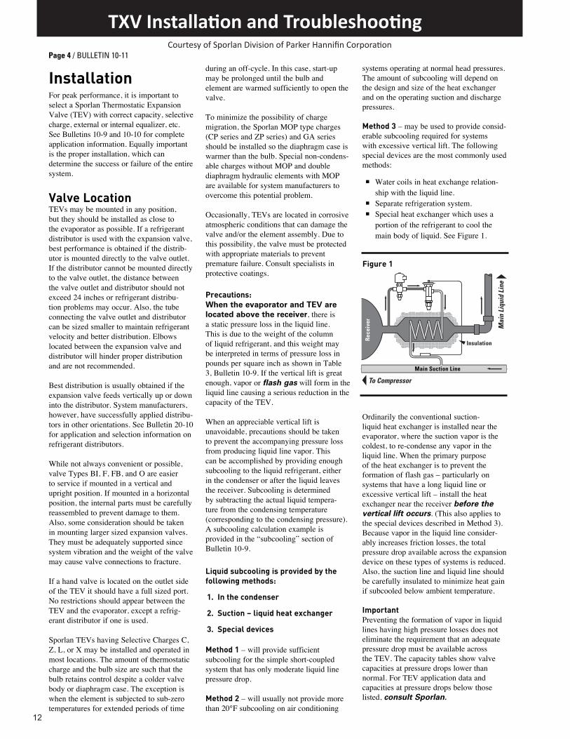
Method 3 – may be used to provide consid-erable subcooling required for systems with excessive vertical lift. The following special devices are the most commonly used methods:
n Water coils in heat exchange relation-ship with the liquid line.
n Separate refrigeration system.n Special heat exchanger which uses a
portion of the refrigerant to cool themain body of liquid. See Figure 1.
Ordinarily the conventional suction-liquid heat exchanger is installed near the evaporator, where the suction vapor is the coldest, to re-condense any vapor in the liquid line. When the primary purpose of the heat exchanger is to prevent the formation of flash gas – particularly on systems that have a long liquid line or excessive vertical lift – install the heat exchanger near the receiver before the vertical lift occurs. (This also applies to the special devices described in Method 3). Because vapor in the liquid line consider-ably increases friction losses, the total pressure drop available across the expansion device on these types of systems is reduced. Also, the suction line and liquid line should be carefully insulated to minimize heat gain if subcooled below ambient temperature.
ImportantPreventing the formation of vapor in liquid lines having high pressure losses does not eliminate the requirement that an adequate pressure drop must be available across the TEV. The capacity tables show valve capacities at pressure drops lower than normal. For TEV application data and capacities at pressure drops below those listed, consult Sporlan.
Page 4 / BULLETIN 10-11
To Compressor
Mai
n Li
quid
Lin
e
Insulation
Main Suction LineRe
ceiv
er
Figure 1
TXV Installation and TroubleshootingCourtesy of Sporlan Division of Parker Hannifin Corporation
13
Solder TechniquesIt is not necessary to disassemble solder type valves when soldering to the connecting lines. Any of the commonly used types of solders, e.g., 95-5, Sil-Fos, Easy-Flo, Phos-Copper, Stay Brite 8 or equivalents may be used for copper to copper connections. When soldering a brass refrigerant distributor to the valve, appropriate solders for these connections, such as 95-5, Easy-Flo, Stay Brite 8 or equivalents must be used. It is important however, regardless of the solder used, to direct the flame away from the valve body and avoid excessive heat on the diaphragm, Figure 2. As an extra precaution, a wet cloth may be wrapped around the body and element during the soldering operation. This precaution will prevent overheating the valve body which could damage the superheat spring and result in flood back problems. In addition, the Type O, EBF/SBF, (E)BQ/SBQ, BBI, CBBI, (E)R/SR, RC and EBS valve contain synthetic parts which can be damaged due to overheating, resulting in poor valve performance.
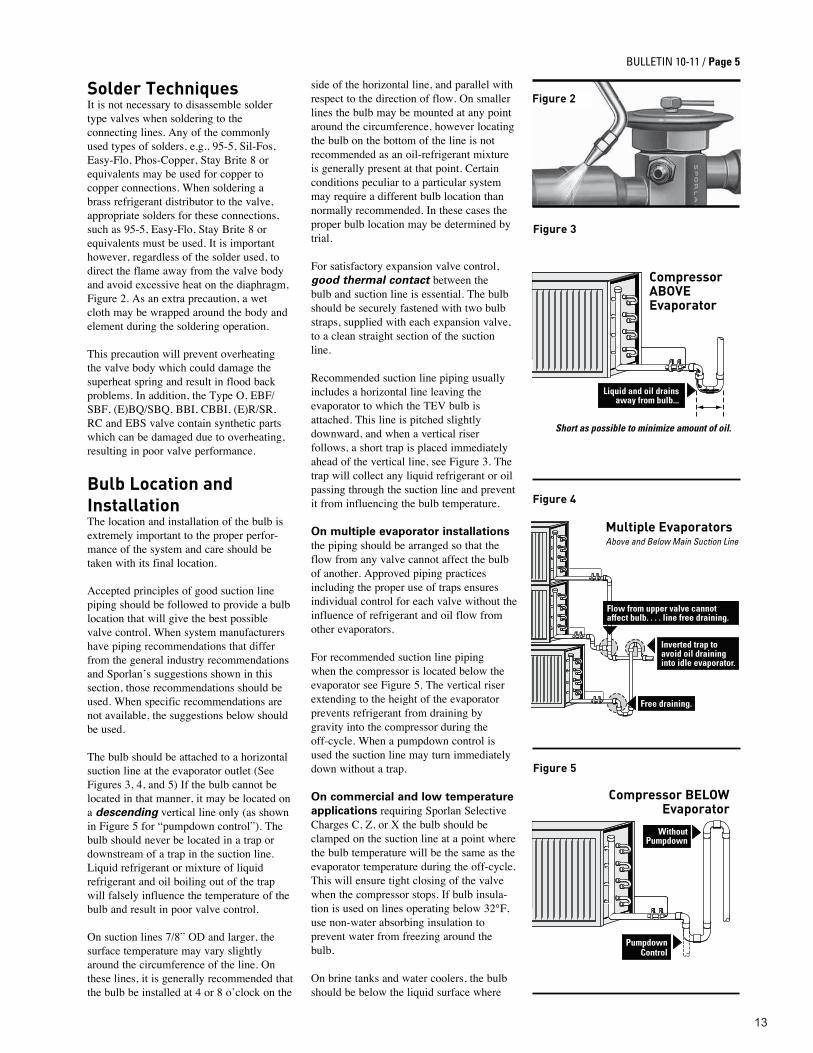
Bulb Location and InstallationThe location and installation of the bulb is extremely important to the proper perfor-mance of the system and care should be taken with its final location. Accepted principles of good suction line piping should be followed to provide a bulb location that will give the best possible valve control. When system manufacturers have piping recommendations that differ from the general industry recommendations and Sporlan’s suggestions shown in this section, those recommendations should be used. When specific recommendations are not available, the suggestions below should be used. The bulb should be attached to a horizontal suction line at the evaporator outlet (See Figures 3, 4, and 5) If the bulb cannot be located in that manner, it may be located on a descending vertical line only (as shown in Figure 5 for “pumpdown control”). The bulb should never be located in a trap or downstream of a trap in the suction line. Liquid refrigerant or mixture of liquid refrigerant and oil boiling out of the trap will falsely influence the temperature of the bulb and result in poor valve control. On suction lines 7/8” OD and larger, the surface temperature may vary slightly around the circumference of the line. On these lines, it is generally recommended that the bulb be installed at 4 or 8 o’clock on the
side of the horizontal line, and parallel with respect to the direction of flow. On smaller lines the bulb may be mounted at any point around the circumference, however locating the bulb on the bottom of the line is not recommended as an oil-refrigerant mixture is generally present at that point. Certain conditions peculiar to a particular system may require a different bulb location than normally recommended. In these cases the proper bulb location may be determined by trial. For satisfactory expansion valve control, good thermal contact between the bulb and suction line is essential. The bulb should be securely fastened with two bulb straps, supplied with each expansion valve, to a clean straight section of the suction line. Recommended suction line piping usually includes a horizontal line leaving the evaporator to which the TEV bulb is attached. This line is pitched slightly downward, and when a vertical riser follows, a short trap is placed immediately ahead of the vertical line, see Figure 3. The trap will collect any liquid refrigerant or oil passing through the suction line and prevent it from influencing the bulb temperature. On multiple evaporator installations the piping should be arranged so that the flow from any valve cannot affect the bulb of another. Approved piping practices including the proper use of traps ensures individual control for each valve without the influence of refrigerant and oil flow from other evaporators. For recommended suction line piping when the compressor is located below the evaporator see Figure 5. The vertical riser extending to the height of the evaporator prevents refrigerant from draining by gravity into the compressor during the off-cycle. When a pumpdown control is used the suction line may turn immediately down without a trap. On commercial and low temperature applications requiring Sporlan Selective Charges C, Z, or X the bulb should be clamped on the suction line at a point where the bulb temperature will be the same as the evaporator temperature during the off-cycle. This will ensure tight closing of the valve when the compressor stops. If bulb insula-tion is used on lines operating below 32°F, use non-water absorbing insulation to prevent water from freezing around the bulb. On brine tanks and water coolers, the bulb should be below the liquid surface where
Figure 2
CompressorABOVEEvaporator
Short as possible to minimize amount of oil.
Liquid and oil drainsaway from bulb...
Multiple EvaporatorsAbove and Below Main Suction Line
Flow from upper valve cannotaffect bulb. . . . line free draining.
Inverted trap toavoid oil draininginto idle evaporator.
Free draining.
Figure 4
Figure 5
Compressor BELOWEvaporator
PumpdownControl
WithoutPumpdown
Figure 3
BULLETIN 10-11 / Page 5

14
it will be at the same temperature as the evaporator during the off-cycle. When locating the bulb in a brine tank, paint it and the capillary tubing with pitch or other corrosion resistant paint.
If, for practical reasons, the bulb must be located where its temperature will be higher than the evaporator during the off-cycle, a solenoid valve must be used ahead of the TEV.
On air conditioning applications having TEVs equipped with CP series or GA series elements, the bulb may be located inside or outside the cooled space or duct. The valve body should not be located in the air stream leaving the evaporator. Avoid locating the bulb in the return air stream unless it is well insulated.
External Equalizer ConnectionFor a complete explanation of when an externally equalized valve should be used, refer to “equalization method,” Bulletin 10-9. Valves supplied with an external equalizer will not operate unless this connection is made.
The equalizer connection should be made at a point that will most accurately reflect the pressure existing in the suction line at the bulb location. See Figure 6. Generally, the connection is immediately downstream of the bulb. However, equipment manufac-turers sometimes locate them in return bends or suction headers that are compat-ible with their specific design requirements. The difference between the pressure at the equalizer connection and the suction pressure at the bulb location should not exceed reasonable pressure drop values. The values shown in Table 1 of Bulletin 10-9 can be used as a guide in determining the value.
If any evaporator pressure or temperature control valves are located in the suction line at or near the evaporator outlet, the equalizer must be connected on the evaporator side of these valves.
TABLE 2
Maximum Dehydration Temperatures - Degrees F
REFRIGERANTThermostatic Charge
L C Z X GA P Type, ZP Series12, 134a 190 190 250
210–
25022, 407C 160 160 185 250404A, 502, 507 150 150 170 –717 (Ammonia) 150 190 235 – – –410A – – – – 250* 250*
* Bulb temperature cannot exceed 160°F.
External EqualizerConnection
It must be connected - NEVER CAPPED!Must be free of crimps, solder, etc.
Figure 6
Figure 7
Page 6 / BULLETIN 10-11
Driers, Strainers, and AccessoriesMost Sporlan TEVs are equipped with built-in screens of varying mesh sizes depending on the valve size and type. These strainers are effective only in removing particles of scale, solder, etc. which could obstruct the closure of the pin and seat.
Moisture and smaller particles of foreign materials are equally harmful to the system and must be removed for peak system performance. Field experience has proven that, without a doubt, most expansion valve failures are due to the presence of dirt, sludge, and moisture in the system. Furthermore, the performance and life of other system components are also seriously affected by these foreign materials. The Sporlan Catch-All Filter-Drier® removes dirt, moisture, acids, and sludge, and ensures the circulation of clean, dry refrig-erant through the system at all times. For all refrigeration and air conditioning applications we recommend that a Sporlan Catch-All Filter-Drier be installed in the liquid line ahead of the TEV. See Bulletin 40-10 for complete Catch-All Filter-Drier specifications.
Further system protection is easily and inexpensively provided with the installa-tion of a Sporlan See-All®. The See-All is a combination liquid and moisture indicator
that visually indicates if there is a shortage of refrigerant in the liquid line, or if the moisture content of the refrigerant is at a dangerous level. See Bulletin 70-10 for complete See-All specifications.
Test Pressures and Dehydration TemperaturesInert dry gases such as nitrogen, helium or CO2 are often used for leak detection.
CAUTION: Inert gases must be added to the system carefully through a pressure regulator. Unregulated gas pressure can seriously damage the system and endanger human life. Never use oxygen or explosive gases. Excessive test pressures can shorten the life of the TEV diaphragm. Table 1 lists the maximum pressure that can safely be applied with the expansion valve connected to the evaporator. These maximum pressures are well above the minimum field leak test pressures for low sides, listed by the ANSI/ASHRAE Standard 15-2001 or latest revision.
The external equalizer line should be disconnected if there is any possibility of exceeding the recommended maximum pressures listed below.
TABLE 1
Maximum Low Side Test PressuresVALVE TYPE psig
(B)I, X, NI, F, FB, (E)BF/SBF, RI, G, EG, C, S, EBS, Small O, (E)Q/SQ, (E)BQ/SBQ, BBI, CBBI, RC, (E)R/SR 450
D, P, H, Large O 425A, M, V, W 400BBI, CBBI, RC, (E)R/SR, (E)BQ/SBQ - R410A ONLY 700

15
If elevated temperatures are used to assist in dehydrating the system, the TEV should not be exposed to temperatures exceeding those shown in Table 2.
Table 2 refers to the maximum dehydration temperatures when the bulb and valve body are subjected to the same temperature. On L, C, Z, and X charges, 250°F maximum valve body temperature is permissible if the bulb temperature does not exceed those shown in the table.
Expansion Valve AdjustmentEach Sporlan TEV is thoroughly tested and set at the factory before shipment. This factory superheat setting will be correct and no further adjustment is required for the majority of applications. However, there are many factors which can affect the performance of a TEV. These factors are independently variable and all of them cannot be compensated for in the design of a valve. When the application or operating conditions require a different valve setting due to one or more of the factors listed below, the valve may be adjusted to obtain the required operating superheat. Therefore, an adjusting stem is provided on all standard valves. The valve should be set with the system as near as possible to design conditions.
Factors which affect valve performance and may make it necessary to adjust the valve are:
1. Low temperature difference (TDs) between the refrigerant and the air
2. TEV bulb location
3. Balance between compressor and evaporator
4. Ratio of load to TEV capacity
5. Condenser capacity
6. Operation of several fixtures on multiple installation
7. Seasonal variation in head pressure caused by extreme changes in ambient air temperature.
Note: Valve Types F, (E)BF/SBF, (E)R/SR, RC, (E)Q/SQ, (E)BQ/SBQ, Q, A, M, V, K, and W have non-rising adjusting stems and a change in adjustment does not change the stem position. When setting valves on multi-evaporator refrigeration systems with pressure or temperature sensitive evaporator control valves, the following procedure is recommended:
1. Evaporator Pressure Regulating Valve (ORI Type): the ORI valve is set first at the minimum load condition. Then, if necessary, the expansion valve is adjusted to the desired superheat setting while under the normal operating load condition.
2. Temperature Sensitive Evaporator Regulating Valves (CDS Type): The CDS valve is forced into a fully open position first. Then the expansion valve is adjusted to the desired superheat setting at full load condition. Finally, the controller for the CDS is set to the desired temperature. Contact Sporlan, or the case manufacturer, for additional details on setting the CDS controller.
When the adjustment is completed on the TEV, always tighten the adjusting stem packing nut and replace the seal cap tightly. Many expansion valves are made non-adjustable for use on Original Equipment Manufacturer’s units, particu-larly those valves used on residential air conditioning and heat pump systems. These valves are set at a superheat predetermined by the manufacturer’s laboratory tests and cannot be adjusted in the field. Some non-adjustable models are modifi-cations of standard adjustable type valves. This is done by using a solid bottom cap instead of one equipped with an adjusting stem and seal cap. These valves can be identified by an N preceding the standard valve designation. Adjustable bottom cap assemblies are available for converting most non-adjustable valves to the adjustable type. However, this is rarely required. If symptoms indicate that a valve adjustment is needed, carefully check the other possible causes of incorrect superheat, pages 8 through 12, before attempting an adjustment.
How to Determine Superheat Correctly
1. Measure the temperature of the suction line at the bulb location.
2. Obtain the suction pressure that exists in the suction line at the bulb location by either of the following methods:
a. If the valve is externally equalized, a gauge in the external equalizer line will indicate the desired pressure directly and accurately.
b. Read the gauge pressure at the suction valve of the compressor. To the pressure add the estimated pressure drop through the suction line between bulb location and compressor suction valve. The
sum of the gauge reading and the estimated pressure drop will equal the approximate suction line pressure at the bulb.
3. Convert the pressure obtained in 2a or 2b above to saturated evaporator temperature by using a temperature-pressure chart.
4. Subtract the two temperatures obtained in 1 and 3 – the difference is superheat.
Figure 8 illustrates a typical example of superheat measurement on an air conditioning system using Refrigerant 22. The temperature of the suction line at the bulb location is read at 52°F. The suction pressure at the compressor is 66 psig and the estimated suction line pressure drop is 2 psi …66 psig + 2 psig = 68 psig at the bulb, which is equivalent to a 40°F saturation temperature. (Use dew point temperature for refrigerant blends.) 40°F subtracted from 52°F = 12°F superheat. Note: Refrigerated case manufacturers frequently use a “temperature difference” method to approximate superheat. This procedure consists of measuring the temper-ature of a location on the evaporator which is representative of saturated vapor tempera-ture; and, then subtracting that temperature from the outlet evaporator temperature which is measured at the bulb location. While this method of reading “superheat” is acceptable on those manufacturer’s cases where the pressure drop through the evaporator is low, Sporlan does not recommend the “temperature difference” method for other types of systems.
How to Change the Superheat Setting Note: There are some valve bodies (G, EG, C, S, EBS and EMC) that have a packing nut around the adjust-ment stem. It may be necessary to loosen the packing nut slightly to turn the adjusting stem. Do not forget to retighten the nut after the superheat is set.
BULLETIN 10-11 / Page 7
What's YourSuperheat?
OBTAIN SUCTION PRESSURE68 PSIG (at bulb)
Temperaturehere reads
524012
SUPERHEAT
Figure 8

16
To reduce the superheat, turn the adjusting stem counter-clockwise. To increase the superheat, turn the adjusting stem clockwise. When adjusting the valve, make no more than one turn of the stem at a time and observe the change in superheat closely to prevent over-shooting the desired setting. As much as 30 minutes may be required for the new balance to take place after an adjustment is made. If in doubt about the correct superheat setting for a particular system, consult the equipment manufacturer. As a general rule, the proper superheat setting will depend on the amount of temperature difference (TD) between refrigerant temperature and the temperature of the air or other substance being cooled. Where high TD’s exist, such as on air conditioning applications, the superheat setting can be made as high as 15°F without noticeable loss in evaporator capacity. Where low TD’s exist, such as in low temperature blower coil applica-tions, a superheat setting of 10°F or below is usually recommended for maximum evaporator capacity. It is these applications that the TEV will more than likely need to be adjusted. For the correct valve setting on factory built equipment, manufacturers’ recommenda-tions should be followed. Some manufac-turers specify the superheat directly; others may recommend valve adjustment to a given suction pressure at certain operating conditions, or until a certain frost line is observed. Such recommendations, however they are stated, represent the results of extensive laboratory testing to determine the best possible operation.
Field Servicing The TEV is erroneously considered by some to be a mysterious and complex device. As a result, many valves are needlessly replaced when the cause of the system malfunction is not immediately recognized. Actually the TEV performs only one very simple function – it keeps the evaporator supplied with enough refrigerant to satisfy all load conditions. It is not a temperature control, suction pressure control, a control to vary the compressor’s running time, or a humidity control. How effective the valve performs is easily determined by measuring the superheat as outlined in Figure 8. Observing the frost on the suction line, or considering only the suction pressure may be misleading. Checking the superheat is the first step in a simple and systematic analysis of TEV performance.
n If not enough refrigerant is being fed to the evaporator—the superheat will be high.
n If too much refrigerant is being fed to the evaporator — the superheat will be low.
Although these symptoms may be attributed to improper TEV control, more frequently the origin of the trouble lies elsewhere. Note: TEVs with permanent bleed ports (BP) or Rapid Pressure Balancer (RPB) construc-tion are applied on many air conditioning and refrigeration systems by original equipment manufacturers. Each application is tested and approved by the manufacturer. The primary function of these devices is to equalize high-to-low side pressures during the off cycle on systems equipped with low starting torque compressors. However, some BP type valves are applied to allow small amounts of liquid refrigerant to pass for compressor motor cooling. The specific function of the feature on a given unit must be determined from the system manufacturer. Once that is determined, it is easier to troubleshoot the system. The primary cause of difficulty with either the BP or RPB feature is dirt and other foreign materials that restrict or plug them. And if the system purpose intended for either feature is not being satisfied, the valve probably needs cleaning or replacing.
As stated in Bulletin 10-9, the RPB type valve is not to be applied on systems using high starting torque compressors or “hard-start” electrical components, on outdoor coils of heat pumps, or on any refrigeration system, and it should not be used to replace BP type valves that are applied on those types of systems. On systems other than those described above, the RPB type valve can replace the BP type valve when necessary. Usually it is advisable to replace a valve with one of the same specification unless advised differ-ently. Consult with the system manufacturer for assistance.
THE CAUSE MAY BE: 1. Moisture — Water or a mixture
of water and oil frozen in the valve port or working parts of the valve will prevent proper operation. This is a common source of trouble on expansion valves. Since the valve is the first cold spot in the system, moisture will freeze and block the valve open, closed, or any position in between. If the valve is frozen in the intermediate position so that flow is restricted, the superheat will be high.
Remedy — Install a Sporlan Catch-All Filter-Drier in the liquid line for removal of moisture from the refrigerant and oil. See Bulletin 40-10.
To determine a safe level of moisture in the system, install a Sporlan See•All Moisture and Liquid Indicator. See Bulletin 70-10.
Excessive moisture has a damaging effect on all system components regardless of the evaporating temperature. Moisture must be removed for trouble-free performance.
2. Dirt or foreign material — Contaminants such as copper oxide scale, metal chips, oil breakdown sludge, etc. will restrict the flow of refrigerant when it collects in strainers or other liquid line accessories. This produces a shortage of refrigerant at the TEV port. Conventional strainers frequently allow the material to pass through the screen and obstruct the flow at the valve port. If a See•All is installed downstream of the restriction, bubbles will be visible. This should not be confused, however, with a refrig-erant shortage or excessive liquid line pressure loss which are also indicated by bubbles in the See•All.
Remedy — Locate and remove the foreign material creating the restric-tion. Install a Sporlan Catch-All Filter-Drier to provide effective filtration of the refrigerant. See Bulletin 40-10.
3. Wax — Certain systems are contami-nated with small amounts of wax which will precipitate at low tempera-tures in systems with Refrigerants 22 or 502. Since the TEV represents the first cold point in the refrigeration cycle, wax is most likely to form at the valve port.
It is sometimes difficult to observe the wax in a valve because it may exist in solid form only at very low temperatures. By the time the valve
Page 8 / BULLETIN 10-11
Complaint “A”“Valve does not feed enough refrigerant.”
SYMPTOMS: n Load temperature (air or water
leaving evaporator) too high. n Superheat too high. n Suction pressure lower than
normal with compressor unloaders locked out or hot gas bypass shut off.*
17
BULLETIN 10-11 / Page 9
has been taken apart, the temperature has increased enough to cause the wax to melt and thus become difficult to detect. When wax is suspected, it can usually be detected on the pin and seat by packing the valve in dry ice while disassembling.
Remedy — Clean the valve with solvent before reassembling the valve. The Sporlan HH style Catch-All Filter-Driers have a special activated charcoal desiccant that is designed to remove wax in the liquid line before it causes trouble. Therefore, to prevent wax problems, use these HH style driers (e.g., C-415-S-HH) on all low temperature systems using Refrigerants 22 or 502.
4. Refrigerant shortage — See•All or sightglass in the liquid line will show bubbles when the system is short of refrigerant charge. Before adding more refrigerant however, be sure the bubbles are not produced by other causes (See Paragraphs A-2 and A-5).
A lack of refrigerant charge may also be detected by a hissing sound at the TEV. Some systems not equipped with a liquid line sightglass will have test cocks or other devices for checking the refrigerant level in the receiver.
Remedy — Add enough refrigerant to obtain desired result.
5. Gas in the liquid line — As explained in Paragraphs A-2 and A-4, liquid line vapor can be produced by a partially plugged strainer or drier and by a shortage of refrigerant charge. In addition, gas in the liquid line can be caused by air or other non-condensable gases in the system or by excessive pressure losses in the liquid line as a result of:
n Long or undersized line. n Liquid line vertical lift.
Remedy — Verify the correct liquid line size for the equivalent length and system tonnage. Consult liquid line sizing data published in many manufacturers’ catalogs and in textbooks. If undersized, repipe with the correct size.
Determine amount of vertical lift, and obtain the resulting pressure loss from Table 3, Bulletin 10-9. Using the subcooling calculation example
provided in the “subcooling” section of Bulletin 10-9, find required subcooling necessary to prevent gasification with the existing pressure losses. Provide the necessary subcooling by using one of the methods described on Page 4.
6. Misapplication of internally equalized valve or incorrect location of external equalizer — If the pressure drop through the evaporator exceeds the predetermined values shown in Table 1, Bulletin 10-9, an externally equalized valve must be used. When an externally equalized valve is used, the equalizer connection should be made at a point in the suction line that will reflect the pressure existing in the line at the bulb location.
Remedy — Replace internally equalized valve with one having an external equalizer.
If external equalizer is installed incorrectly, change to correct location. See Page 6.
7. Insufficient pressure drop across valve — One of the factors that influence expansion valve capacity is the pressure drop that exists between the inlet and outlet. Anything contrib-uting to a reduction in this pressure drop will reduce valve capacity. Abnormally low condensing pressures, excessive liquid line pressure losses (even with adequate subcooling), undersized distributor nozzle or distrib-utor tubes may also be responsible for a very low net pressure drop across the valve port.
Remedy — Remove source of pressure loss, or install valve with adequate capacity at the reduced pressure drop. If inlet pressure to valve is low due to low condensing pressure, raise pressure.
If the refrigerant distributor nozzle is undersized replace with correct size. See Bulletin 20-10.
8. Dead thermostatic element or wrong thermostatic charge — If the element has partially or completely lost its thermostatic charge, the valve will be unable to feed sufficient refrig-erant or will remain closed. A wrong charge may cause insufficient feed also.
Remedy — Replace the element if it is dead. If charge is incorrect, replace with proper selective charge. See Bulletin 10-9.
9. Charge migration (CP series, ZP series, and VGA charges only) — In order for valves with these charges to maintain control at the bulb, the bulb must be kept at a lower temperature than the element (diaphragm case). If the thermostatic charge does migrate to the element because of a lower element temperature, the valve will throttle.
Detection — Warm the element with a cloth saturated with hot water. If this produces more refrigerant feed and reduces the superheat to normal, charge migration is responsible for the starved evaporator.
Causes — n Insufficient pressure drop between
the valve outlet and bulb location, possibly due to an oversized distrib-utor nozzle or no nozzle at all.
n Excessive pushrod leakage, which allows the leaking refrigerant to cool the diaphragm case before passing into the equalizer line. This is a rare occurrence and should be carefully checked before arriving at this conclusion.
n Cold location of TEV, or condensate drippage on the diaphragm case.
Remedies — n Install distributor nozzle correctly
sized in accordance with nozzle sizing procedure given in Sporlan Bulletin 20-10.
n On valves with packed pushrod construction, remove element and tighten the pushrod packing nuts.
n Relocate the TEV away from cold outlet air, or condensate drippage.
10. Undersized valve
Remedy — Install valve sized in accordance with procedure given in Bulletin 10-9, or Bulletin 10-10.
11. High Superheat adjustment Remedy — Turn the adjusting stem
counter clockwise until the correct superheat is indicated.
12. Feed-back from another valve — Review instructions for Bulb Location and Installation, Page 5.
* When system has some form of capacity reduction — cylinder unloaders or hot gas bypass, a low suction pressure will not exist. Therefore, when checking TEV performance, a better analysis is possible when these devices are locked out or shut off so the suction pressure will respond to variations in load or valve feed.

18
Remedy — Check the bulb tempera-ture and calculate the superheat. If superheat is normal but too little refrigerant is flowing through the evaporator, check the piping for possible refrigerant flow from another evaporator affecting the bulb. Re-pipe if necessary. See Figure 4.
13. High pressure drop through evaporator
Remedy — Check the pressure at the evaporator inlet and outlet with gauges. If pressure difference is greater than the values shown in Table 1, Bulletin 10-9, use an externally equalized valve.
14. Restricted, plugged, or capped external equalizer — If the pressure under the diaphragm builds up due to pushrod leakage and cannot escape through the external equalizer line, the valve will remain closed.
Remedy — Check the external equalizer line to be sure it is open or not capped.
THE CAUSE MAY BE: 1. Moisture — Water or a mixture of
water and oil frozen in the valve port or working parts of the valve will prevent proper operation. This is the most common source of trouble on TEVs. Since the valve is the first cold spot in the system, moisture will freeze and block the valve open, closed, or any position in between. If the valve is held in the open position by ice, liquid flood-back will occur.
Remedy — Install a Sporlan Catch-All Filter-Drier in the liquid line for removal of moisture from the refrigerant and oil. See Bulletin 40-10.
For additional protection, install a Sporlan See•All Moisture and Liquid Indicator for a positive indication of when a safe moisture level is reached. See Bulletin 70-10.
2. Dirt or foreign material — Contaminants such as copper oxide
scale, metal chips, oil breakdown sludge, etc. may pass through ordinary strainers and lodge at the TEV port and prevent the valve from closing.
Remedy — Disassemble the valve and remove all foreign material from the internal parts. Install a Sporlan Catch-All Filter-Drier in the liquid line. The Catch-All filters out the smallest particles of foreign material that might interfere with the operation of any system component.
3. Expansion valve seat leak — When the valve port does not seat tightly, refrigerant will pass through during the off-cycle and fill the evaporator with refrigerant. If the seat leak is severe, the valve will feed too much refrigerant during the operating cycle as well. (Not applicable to valves with permanent bleed ports or RPB feature.)
Remedy — If the valve seat is leaking, a gurgling or hissing sound can usually be heard during the off-cycle. Also, a sightglass or See•All in the liquid line may indicate continued refrigerant flow for a long period after the compressor has stopped. Make certain however, that the bubbles are not the result of back-flow through a vertical liquid line.
Disassemble the valve to be certain that dirt or foreign material is not respon-sible (see B-2). If the pin and seat are worn or damaged and an internal parts kit is available, replace the parts. When parts are not available, the valve must be replaced.
4. Oversized valve — Check valve ratings considering all the factors which affect its capacity. See Page 16, Bulletin 10-9, or Page 3, Bulletin 10-10.
Remedy — Install correctly sized valve.
5. Incorrect bulb installation — The bulb should be securely fastened to a straight, clean, section of the suction line using two bulb straps for good thermal contact. Also, the temperature of the bulb should not be influenced by ambient temperature — an external heat source such as a steam pipe or heating coil.
Remedy — Install bulb correctly. See Bulb Location and Installation, Page 5.
6. Low superheat adjustment Remedy — Turn the adjusting stem
clockwise until the correct superheat is indicated. See Page 7.
7. Incorrect thermostatic charge
Remedy — Select and install the correct selective charge. See Bulletin 10-9.
8. Incorrectly located external equalizer
Remedy — Relocate external
equalizer or the connection between evaporator and any other temperature or pressure sensitive evaporator control valve near bulb location. See Page 6 for recommendations.
9. Inefficient compressor — If the compressor is inefficient or for some other reason lacks capacity, the suction pressure will operate higher than normal. This may or may not be accompanied by low superheats.
Remedy — Consult with compressor manufacturer.
THE CAUSE MAY BE: 1. Refrigerant drainage — Drainage
of refrigerant from the evaporator (during the off-cycle) when installed at a higher level than the compressor.
Remedy — Install a trap-riser to top of evaporator or use pump-down control. See Figure 5.
2. Compressor or suction line in cold location — During the period when the system is not in operation, liquid refrig-erant will condense at the coldest point in the system. Liquid will condense in the compressor or suction line, if they are located in an ambient temperature below that of the evaporator during the off-cycle. Upon re-starting, this liquid will slug the compressor.
Remedy — Keep compressor or suction line warm during the off-cycle. Some compressors are equipped with crankcase heaters for this purpose. Another corrective measure is to install
Page 10 / BULLETIN 10-11
Complaint “B” “Valve feeds too much refrigerant.”
SYMPTOMS: n Liquid returns to compressor. n Superheat is low. n Suction pressure is normal or
higher than normal.
Complaint “C”“Valve feeds too much
refrigerant at start-up only.”
SYMPTOMS: n Liquid returns to compressor. n No superheat. n Suction pressure higher than
normal.

19
BULLETIN 10-11 / Page 11
a suction line solenoid valve that is de-energized during the off-cycle.
3. Restricted or plugged external equalizer — A momentary flood can occur when the load increases suddenly, such as at start-up because the higher suction pressure cannot reach the underside of the diaphragm and help close the valve. If the pressure under the diaphragm increases due to any pressure leakage around the pushrods, the valve will eventually throttle.
Remedy — Remove the restriction or plugged portion of the external equalizer.
4. Liquid line solenoid valve seat leak or interrupted pumpdown — Liquid refrigerant can continue to feed the TEV and/or remain in evaporator upon shut-down causing flood-back to the compressor upon start-up.
Remedy — Disassemble and clean solenoid valve and/or replace damaged internal parts if seat leakage is the problem. If the pumpdown cycle isn’t completed before the compressor cycles off, or the thermostat calls for cooling and reopens the liquid line solenoid before the evaporator has been properly evacuated, check the low pressure cut-off setting or the electrical controls for possible causes.
THE CAUSE MAY BE: 1. Unequal circuit loading
(Multi-circuit evaporators and parallel evaporators connected to a single refrigerant distributor) — When each circuit is not subjected to the same heat load, the lightly loaded circuits will allow unevaporated refrigerant or low temperature vapor
to enter the suction line and throttle the valve. This will cause normally loaded circuits to be deprived of their share of refrigerant. The net result is a loss of refrigerated evaporator surface.
Remedy — Make necessary modifica-tions which will allow each evaporator circuit to receive the same percentage of the total load. See Bulletin 20-10 for application information on multi-circuit evaporators using a refrigerant distributor.
2. Poor refrigerant distribution (Multi-circuit evaporators and parallel evaporators connected to a single refrigerant distributor) — If the refrigerant distribution is faulty, the circuits receiving the largest portion of refrigerant will have the controlling influence on the TEV. The result is the same as in paragraph D-1.
Remedy — Correct refrigerant distri-bution. See Bulletin 20-10 for complete information on Refrigerant Distributors.
3. Low load— Low evaporator load may be caused by insufficient air over the coil as a result of an undersized blower, dirty air filters, or an obstruc-tion in the air stream. In addition, frost formation on the coil or low entering air temperatures will reduce the evaporator load.
Remedy — Correct the condition responsible.
4. Flow from one coil affecting TEV bulb of another (Multiple evaporator systems only) — The temperature of the bulb may be falsely influenced by flow from another evaporator usually because of incorrect piping.
Remedy — Correct the piping. See Figure 4, Page 5.
5. Improper compressor-evaporator balance — If the compressor is too large for the load and evaporator capacity, the low suction pressure which results will cause poor system performance.
Remedy — Consult with the manufac-turer or consulting engineer, or the ASHRAE Handbook on component balancing. If necessary, change or correct the improperly sized
component. Hot gas bypass may be used to balance properly.
6. Evaporator oil-logged — Poor heat transfer occurs and unpredict-able performance takes place. If erratic performance is observed over a period of time, and other causes are omitted from consideration, review the amount of oil in the system. Turbulent compressor oil level with little or no return to the compressor sump indicates oil problems.
Remedy — Remove excessive oil from evaporator and connecting piping. Many times the evaporator tempera-ture will be too low for the oil to be removed. Therefore, the system must be allowed to warm sufficiently to get cold oil to drain. Analyze system components for possible causes of oil problem before restarting the system. Consult with the compressor manufac-turer for specific details on their compressor.
THE CAUSE MAY BE: 1. System characteristics — Certain
design characteristics of the system may have an effect on the system’s tendency to hunt or cycle. As an example, after the valve admits refrig-erant to the evaporator inlet, there is a time delay before the bulb senses the effect at the evaporator outlet. This time delay is dependent on evaporator length, tube size, and load. Generally, there is more likelihood for hunting to occur when this time interval is long. Other influencing factors are circuit arrangement, load per circuit, and temperature difference.
Remedy — When hunting is moderate particularly with no floodback, the effect on the system is insignificant and corrections are not necessary. If hunting is severe with floodback to the compressor, check the possible remedies shown in the following paragraphs.
Complaint “D”“Valve doesn’t feed properly.”
SYMPTOMS: n Poor system performance. n Superheat normal or lower
than normal. n Suction pressure lower than
normal with compressor unloaders locked out or hot gas bypass shut off.*
Complaint “E”“System hunts or cycles.”
SYMPTOMS: n Suction pressure fluctuates* n Superheat fluctuates. n Valve does not feed enough,
and then too much refrigerant.
* When system has some form of capacity reduction — cylinder unloaders or hot gas bypass, a low suction pressure will not exist. Therefore, when checking TEV performance, a better analysis is possible when these devices are locked out or shut off so the suction pressure will respond to variations in load or valve feed.

20
2. Valve size — An over-sized valve usually aggravates hunting. Carefully check the valve rating considering all the factors affecting its capacity. See Bulletin 10-9, or Bulletin 10-10.
Remedy — Replace valve with one correctly sized. On multiple circuit evaporators using a refrigerant distrib-utor, the capacity of the valve can be reduced, within certain limits, by installing a smaller distributor nozzle. See Bulletin 20-10.
3. Bulb location — If the bulb is located in a suction line trap, its tempera-ture will be affected by liquid oil and refrigerant alternately collecting and evaporating at this point. This condition frequently results in severe hunting.
Remedy — As a temporary measure relocate the bulb away from the trap, and any turbulent areas created by elbows, tees, etc. Also remove the bulb from the air stream or insulate. Re-pipe if necessary. Sometimes another position around the circumfer-ence of the suction line will minimize hunting. Follow the Bulb Location and Installation instructions given on Page 5 for the best TEV control.
4. Refrigerant and load distribution — In addition to the effects of poor distribution explained in paragraphs D-1 and D-2, hunting also frequently results. This is caused by liquid refrigerant from the overfed circuits occasionally reaching the bulb of the valve.
Remedy — Correct the faulty distri-bution.
5. Superheat adjustment — All Sporlan TEVs are preset at the factory to give the best performance on the average system. A valve should not be adjusted unnecessarily, but occasion-ally another setting may prove to be better.
Remedy — Turn the adjusting stem clockwise a turn at a time. If the hunting stops or is reduced, turn the adjusting stem counter clockwise a turn at a time to obtain the lowest superheat with stable operation.
6. Moisture — As ice forms in a TEV from excessive moisture, a very erratic hunt may result.
Remedy — Remove the moisture with the installation of a Sporlan Catch-All Filter-Drier. A safe moisture level can
be determined by installing a Sporlan See•All.
THE CAUSE MAY BE: 1. No refrigerant being fed to
evaporator. See Section A on Pages 8 & 9.
2. Too much refrigerant being fed to evaporator. See Section B on Page 10.
3. Too much refrigerant being fed to evaporator at start-up only. See Section C on Page 10.
4. Refrigerant control is erratic. See Section D on Page11.
5. System is hunting or cycling. See Section E on Page11.
6. The TEV has been physically abused in an effort to make the valve work properly. This is usually the result of a mistaken analysis. It is frequently assumed that if a valve does not feed properly, it is stuck (either opened or closed). Beating the valve body with a hammer will only distort the body and make it impossible for the valve to work once the real cause is determined.
If a valve “sticks,” it is usually due to moisture freezing in the port, dirt and other foreign material restricting or plugging the internal parts, wax forming on the internal parts at low temperatures, or the valve has been physically abused so it cannot function.
Remedy — Inspect the valve and its internal parts, including the inlet strainer. If plugged or restricted in any way, clean the parts thoroughly, oil the parts with a good grade of refrigerant oil, and reassemble the parts. Complete details on this subject are found on Pages 13 through 14.
If the valve is beyond normal cleaning processes, or if it is physically damaged in any way, replace the valve with its proper replacement model.
Field Assembly InstructionsNote: These Field Assembly Instructions apply in part to all Sporlan TEVs. See Figure 9 for an “exploded” view of those models that can be completely disassem-bled. When a TEV is to be disassembled for inspection and cleaning, or for replacement of the thermostatic element or the internal parts, the following information should be reviewed for assistance.
Types F dated approximately C84 or earlier and Types I, BI, NI, RI, FB manufactured prior to 1994 do not have replaceable elements nor internal parts kits, but can be disassembled for inspection and cleaning. Type F dated D84 or later, Type S valves dated B69 or later, Type C valves dated C70 or later, and ALL Type G, X, (E)BF/SBF and EBS valves employ packless pushrod construction and internal parts are NOT available for use with them. However, their elements can be replaced and they can be disassembled for inspec-tion and cleaning. Due to the single pushrod construction of the Type (E)BF/SBF and EBS valves, only the bottom cap assembly, pin guide, and superheat spring may be removed for inspection and cleaning.
Early production of the Type F valve with the replaceable element requires a 15/16” thin jaw, open end type element wrench such as a Bonney 1230. Subsequent produc-tion of the Type F valve and all Types BBI, CBBI, RC, (E)R/SR, (E)Q/SQ, (E)BQ/SBQ, (E)BF/SBF, I, BI, NI, RI, and FB valves require a 1” thin jaw, open end type element wrench such as the one available from Sporlan wholesalers. An open end wrench is necessary because of limited space between the body and element of these valves. Precautions must be taken in removing the KT-43 element (F) so the element, body, or connections are not damaged by the wrenches.
While standard open end or adjustable wrenches fit the other element sizes, the thin jaw type wrenches are also available for the other element sizes: Bonney 1236 (1-1/8”) for KT-53 elements, Bonney 1240 (1-1/4”) for KT-83 elements, Bonney 1248 for KT-33 elements, and Bonney 1252 for KT-63 and 7 elements.
Replaceable elements and internal parts kits are available for current valves with packed pushrod construction:Types P, H, M, D, and A.
Replaceable elements for Types O, V, W, and U are also available. However, special
Page 12 / BULLETIN 10-11
Complaint “F”“System won’t perform properly.”
SYMPTOM: n Cannot get valve to react or
regulate at all.

21
Bulletin# RAE-WARR-0816Page 1 of 2 (Important information on page 2)
DIVISIONS RAE CORPORATION
4492 Hunt St. • Pryor, OK 74361 • (918) 825-7222 • Fax (918) 825-6366
C O I L S
RAE Corporation Express Limited and Extended Express Limited WarrantyThe Express Limited Warranty and Extended Express Limited Warranty are only available to customers if the Start Up Warranty Checklist and Warranty Registration Card is completed and returned to RAE Corp. service department. The Start Up Warranty Checklist must be; (1) completed at the time of start up, (2) dated and signed by the technician, and (3) forwarded with the warranty registration card to the RAE Corp. service department for warranty validation within 10 days after startup. The Start Up Warranty Checklist and Warranty registration Card are included with each product sold.
1. Express Limited WarrantySubject to the terms, limitations, and disclaimer provisions set forth herein, RAE Corp. warrants to the original Purchaser that products manufactured by RAE Corp. shall be free from defects in material and workmanship under normal use and service. This limited warranty, which covers material and workmanship, has a limited duration which is as follows: the limited warranty commences on the date that RAE Corp. issues its invoice to the Purchaser for the equipment, and extends thereafter until the limited warranty expiration date. The limited warranty expiration date is the earlier of the following: eighteen (18) months from and after the issuance of RAE’s invoice to the Purchaser, or twelve (12) months from and after the start-up of the equipment that is the subject of the invoice.This warranty is issued only to the original Purchaser, is not transferable, applies only to a unit installed within the United States of America, its territories or possessions and Canada and is in lieu of all other warranties expressed or implied. RAE Corp. neither assumes, nor authorizes any other person to issue or assume for RAE Corp., any obligations or liabilities not herein stated.It is agreed that in the event of breach of any of the express warranties described herein, the liability of RAE Corp. shall be limited to RAE Corp. repairing or replacing the non-conforming goods. RAE Corp. will repair or replace, free of cost to Purchase-User, F.O.B. RAE Corp. factory, any part or parts that in RAE Corp.’s judgment is defective. Upon RAE Corp. authorization, the said part or parts should be returned to RAE Corp., transportation prepaid by purchaser, for inspection and judgment. RAE Corp. assumes no responsibility for the expense of labor or materials necessary to remove a defective part or install repaired or new
2. Extended Express Limited WarrantyA four-year Extended Express Limited Warranty (“Extended Warranty”) may be purchased at the time of purchase. The warranty runs until an additional 4 years after expiration of the Express Limited Warranty. The Extended Warranty must be purchased prior to the startup date. RAE Corp., at its sole discretion, may authorize the purchase of an extended warranty after the unit is initially started, based on approval of the provided startup documentation. The Extended Warranty is limited to the original purchaser and may not be transferred to subsequent purchasers.
3. General Disclaimers and Limitations on WarrantyRAE CORP. DISCLAIMS, AND MAKES NO WARRANTY OF MERCHANTABILITY AND NO WARRANTY OF FITNESS FOR ANY PARTICULAR PURPOSE, NOR DOES IT MAKE ANY WARRANTY, EXPRESS OR IMPLIED, OF ANY NATURE WHATSOEVER WITH RESPECT TO PRODUCTS SOLD BY RAE CORP. OR THE USE THEREOF EXCEPT AS IS SPECIFICALLY SET FORTH ON THE FACE HEREOF. THIS WARRANTY, WHICH IS GIVEN EXPRESSLY AND IN LIEU OF ALL OTHER WARRANTIES, EXPRESS OR IMPLIED CONSTITUTES THE ONLY WARRANTY MADE BY THE SELLER. THIS LIMITED WARRANTY DOES NOT COVER OR PROTECT AGAINST THE CONSEQUENCES OR EFFECTS OF ANY MISUSE, NEGLECT, OR USE OF THE EQUIPMENT OUTSIDE OF THE PURPOSES OR PARAMETERS FOR WHICH THE EQUIPMENT WAS DESIGNED.RAE CORP. SHALL IN NO EVENT BE LIABLE FOR DIRECT, INDIRECT, SPECIAL, INCIDENTAL, CONSEQUENTIAL OR PENAL DAMAGES. RAE CORP. MAKES NO WARRANTY OF ANY KIND, EITHER EXPRESS OR IMPLIED, TO ‘CONSUMERS’ AS THAT TERM IS DEFINED IN SEC. 101 OF PUBLIC LAW 93-637, THE MAGNUSON-MOSS WARRANTY-FEDERAL TRADE COMMISSION IMPROVEMENT ACT.RAE CORP. SHALL NOT BE LIABLE FOR ANY DAMAGE OR DELAYS OCCURRING IN TRANSIT, FOR ANY DEFAULT OR DELAYS IN PERFORMANCE CAUSED BY ANY CONTINGENCY BEYOND ITS CONTROL INCLUDING WAR, GOVERNMENT RESTRICTIONS OR RESTRAINTS, STRIKES, SHORT OR REDUCED SUPPLY OF RAW MATERIALS, FIRE, FLOOD OR OTHER ACTS OF GOD, NOR FOR DAMAGE OR LOSS OF ANY PRODUCTS, REFRIGERANT, PROPERTY, LOSS OF INCOME OR PROFIT DUE TO MALFUNCTIONING OF SAID UNIT.ANY AND ALL CONTROVERSIES, ISSUES, CLAIMS OR DISPUTES RELATING TO THIS PURCHASE AND SALE TRANSACTION, INCLUDING BUT NOT LIMITED TO, ANY CONTROVERSIES, ISSUES, CLAIMS AND DISPUTES CONCERNING THE INTERPRETATION OR ENFORCEMENT OF ANY WARRANTY ( OR ANY LIMITATION OR OTHER ASPECT THEREOF), SHALL BE GOVERNED BY OKLAHOMA LAW.

22
Bulletin# RAE-WARR-0816Page 2 of 2
4. Specific Limitations to WarrantyParts OnlyThis warranty is limited to repair or replacement of defective parts only and does not include labor. RAE Corp., at its sole discretion, may preauthorize the inclusion of labor expense. No claim for labor charges will be allowed without a written preauthorization from RAE Corp.’s service department. Prior written approval from RAE Corp. is required, in the event RAE Corp. has authorized the customer to purchase replacement parts for any warranted parts; and, such replacement parts must be obtained directly from a manufacturer’s representative or RAE Corp. Claims for replacement parts obtained locally will be disallowed unless accompanied by a RAE Corp. purchase order for such replacement parts. Orders for warranty replacement parts will be shipped ground transportation prepaid using the most appropriate transportation method. Any premium transportation service will be at the cost of the requestor.Export EquipmentEquipment exported outside the United States will be covered under the same parts only warranty as non exported equipment; provided that, all warranty transactions must take place within the territorial United States. Parts covered under warranty must be paid for in advance of any parts shipment. The customer will be reimbursed upon return of the warranty part and after the part has been inspected and determined defective. All exporting paperwork and shipping costs, including crating, will be the responsibility of the party ordering the part.Initial InspectionRAE Corp. will not be responsible for shipping damage, or for parts lost in transit, or for any claims of concealed damage. It is the responsibility of the receiving party to thoroughly inspect the equipment upon delivery for damage, refrigerant leaks or dry nitrogen pressure loss in transit, and to verify that any loose parts have been included in the shipment. The bill of lading will indicate if parts are shipped loose in the unit. If shipping damage has occurred, or loose parts are missing, the receiving party must resolve the issue through the claim process with the company responsible for transporting the equipment.RefrigerantRefrigerant is excluded from the warranty. RAE Corp., at its sole discretion, may preauthorize the inclusion of refrigerant. No payment will be made for any leak that occurs at a threaded, mechanical joint (defined as flare joints, pipe thread joints or rotolock joints). It is the responsibility of the Contractor to check these joints upon arrival of the equipment or prior to charging the system. Any claim for refrigerant reimbursement must be pre-authorized by RAE Corp.’s service department and a purchase order
5. DOA Warranty ProblemsIn the event of a DOA problem, the purchaser must notify and contact the RAE Corp. service department or the selling representative and provide the unit Model Number, Serial Number, complete problem description and estimate for repair. If repairs are authorized by RAE Corp., the RAE Corp. service department may:
A. Authorize the job site contractor to make the repairs.B. Select a different contractor to make the repairs.C. Dispatch a factory technician to make the repairs. If field repairs are authorized, a RAE Corporation purchase order will
be issued in the amount of the approved repair cost (including parts, material and labor), and repairs can be performed. Upon completion of repairs, the contractor is to send the invoice referencing the purchase order number to the service department with supporting documentation, including a service report and parts/material invoices. No back charges or service billings will be accepted without prior authorization by the service department.
A DOA problem is a defect in material or workmanship that prevents a successful start up of the unit. The problem will be
6. Compressor ReplacementsIn the event a compressor fails, RAE Corp. service department must be notified by telephone or e-mail within 24 hours of discovering the compressor failure for the compressor to be covered by warranty. The customer must provide RAE Corp. service department with the Unit Model Number, Unit Serial Number, Compressor Model Number, and Compressor Serial Number before any replacement will be provided. RAE Corp. reserves the right to determine the source of the replacement compressor. The failed compressor body core must be returned to the re-manufacturer or the wholesale house as determined by RAE Corp. service department before the compressor will be replaced pursuant to this warranty. If the core is not returned, the customer will be invoiced for the compressor and the
7. Notice to RAE CorporationTo contact and/or notify RAE Corporation Service Department the following contact information must be used:
Address: 4492 Hunt St., Pryor, OK 74361Office Phone: 918-825-7222After Hours Emergency Cell Phone: 918-633-2838Fax: 918-825-6366Email: [email protected]
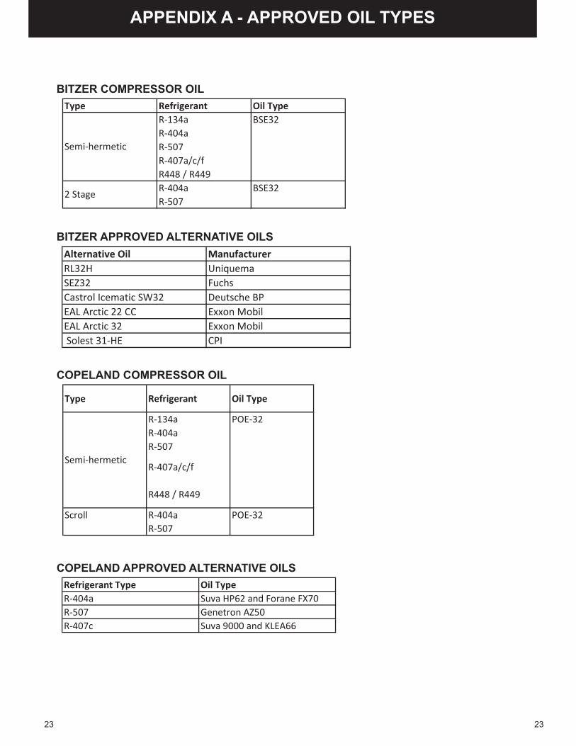
2323
BITZER COMPRESSOR OIL
COPELAND APPROVED ALTERNATIVE OILS
COPELAND COMPRESSOR OIL
BITZER APPROVED ALTERNATIVE OILSAlternative Oil ManufacturerRL32H UniquemaSEZ32 FuchsCastrol Icematic SW32 Deutsche BPEAL Arctic 22 CC Exxon MobilEAL Arctic 32 Exxon Mobil Solest 31-HE CPI
Type Refrigerant Oil TypeR-134aR-404aR-507R-407a/c/fR448 / R449R-404aR-507
BSE32
BSE32
Semi-hermetic
2 Stage
Type Refrigerant Oil Type
R-134aR-404aR-507
R-407a/c/f
R448 / R449
R-404aR-507
POE-32
Semi-hermetic
Scroll POE-32
Refrigerant Type Oil TypeR-404a Suva HP62 and Forane FX70R-507 Genetron AZ50R-407c Suva 9000 and KLEA66
APPENDIX A - APPROVED OIL TYPES

24
APPENDIX B - TEMPERATURE PRESSURE CHARTS
°F R-404a R-507 R-407a R-407c R-407f R-448a R-449a R-134a R-410a R-22-40 4 5 1 -2 0 0 0 -7 11 1-38 5 6 0 -2 1 1 1 -7 12 1-36 6 8 1 1 1 2 2 -6 13 2-34 7 9 1 0 2 3 3 -6 15 3-32 8 10 2 1 3 3 3 -5 16 4-30 10 11 3 2 4 4 4 -5 18 5-28 11 12 4 3 5 5 5 -4 19 6-26 12 13 5 3 6 6 6 -4 21 7-24 13 15 6 4 7 8 8 -3 23 8-22 15 16 7 5 9 9 9 -2 25 9-20 16 18 8 6 10 10 10 -2 26 10-18 17 19 10 8 11 11 11 -1 28 11-16 19 21 11 9 12 12 12 0 30 13-14 20 22 12 10 14 14 14 0 32 14-12 22 24 13 11 15 15 15 1 34 15-10 24 26 15 12 16 16 16 2 36 17-8 25 27 16 14 18 18 18 3 39 18-6 27 29 18 15 19 19 19 4 41 19-4 29 31 19 16 21 21 21 5 43 21-2 31 33 21 18 23 23 23 5 46 220 33 35 23 19 24 24 24 6 48 242 35 37 24 21 26 26 26 7 51 264 37 39 26 23 28 28 28 9 54 276 39 41 28 24 30 30 30 10 57 298 41 43 30 26 32 32 32 11 59 3110 43 46 32 28 34 34 34 12 62 3312 45 48 34 30 36 36 36 13 65 3514 48 51 36 32 38 38 38 14 69 3716 50 53 38 34 40 40 40 16 72 3918 53 56 40 36 43 42 42 17 75 4120 55 58 42 38 45 45 44 18 79 4322 58 61 45 40 48 47 47 20 82 4524 61 64 47 42 50 49 49 21 86 4826 63 67 50 45 53 52 52 23 90 5028 66 70 52 47 55 55 54 24 93 5230 69 73 55 50 58 57 57 26 97 5532 72 76 58 52 61 60 60 28 101 5834 75 79 60 55 64 63 63 30 106 6036 79 82 63 57 67 66 66 31 110 6338 82 86 66 60 70 69 69 33 114 6640 85 89 69 63 73 72 72 35 119 6942 89 93 73 66 77 75 75 37 123 7244 92 96 76 69 80 79 78 39 128 7546 96 100 79 72 84 82 82 41 133 7848 100 104 83 76 87 85 85 43 138 81
For blend refrigerants the Dew Point is used for 50°F and below.
˚F
Pressure in PSIG

25
APPENDIX B - TEMPERATURE PRESSURE CHARTS
°F R-404a R-507 R-407a R-407c R-407f R-448a R-449a R-134a R-410a R-2250 104 108 86 79 91 89 89 45 143 8452 109 112 108 101 114 112 110 48 148 8754 113 116 112 105 118 116 114 50 154 9156 117 120 116 109 123 120 118 52 159 9458 121 125 120 113 127 124 122 55 165 9860 126 129 125 117 132 129 127 57 171 10262 130 134 129 122 136 134 131 60 177 10564 135 138 134 126 141 138 136 63 183 10966 139 143 139 131 146 143 141 65 189 11368 144 148 143 135 151 148 146 68 195 11770 149 153 148 140 156 153 150 71 202 12172 154 158 153 145 162 158 156 74 208 12674 159 163 159 150 167 163 161 77 215 13076 164 169 164 155 173 169 166 80 222 13478 169 174 169 160 178 174 172 83 229 13980 175 180 175 165 184 180 177 87 237 14482 180 185 180 171 190 186 183 90 244 14884 186 191 186 176 196 192 189 93 252 15386 192 197 192 182 202 198 194 97 259 15888 198 203 198 188 209 204 201 101 267 16390 204 209 204 194 215 210 207 104 275 16892 210 216 211 200 222 216 213 108 284 17494 216 222 217 206 228 223 219 112 292 17996 223 229 224 212 235 230 226 116 301 18598 230 235 230 218 242 236 233 120 310 190100 236 242 237 225 249 243 240 124 319 196102 243 249 244 232 257 250 247 128 328 202104 250 256 251 238 264 257 254 133 337 208106 257 264 258 245 272 265 261 137 347 214108 265 271 266 253 279 272 268 142 356 220110 272 279 273 260 287 280 276 146 366 226112 280 287 281 267 295 288 284 151 377 233114 287 295 289 275 303 296 291 156 387 239116 295 303 297 282 312 304 299 161 398 246118 303 311 305 290 320 312 308 166 408 253120 312 319 313 298 329 320 316 171 419 260122 320 328 322 306 338 329 324 176 431 267124 328 337 331 314 347 338 333 182 442 274126 337 345 339 323 356 347 342 187 454 282128 346 355 348 331 365 356 351 193 466 289130 355 364 357 340 375 365 360 199 478 297132 364 373 367 349 385 374 369 205 490 305134 374 383 376 358 395 384 378 211 503 313136 383 393 386 367 405 393 388 217 516 321138 393 403 396 377 415 403 398 223 529 329140 403 413 406 386 425 413 408 229 543 337
For blend refrigerants the Dew Point is used for 50°F and below.
Pressure in PSIG
˚F
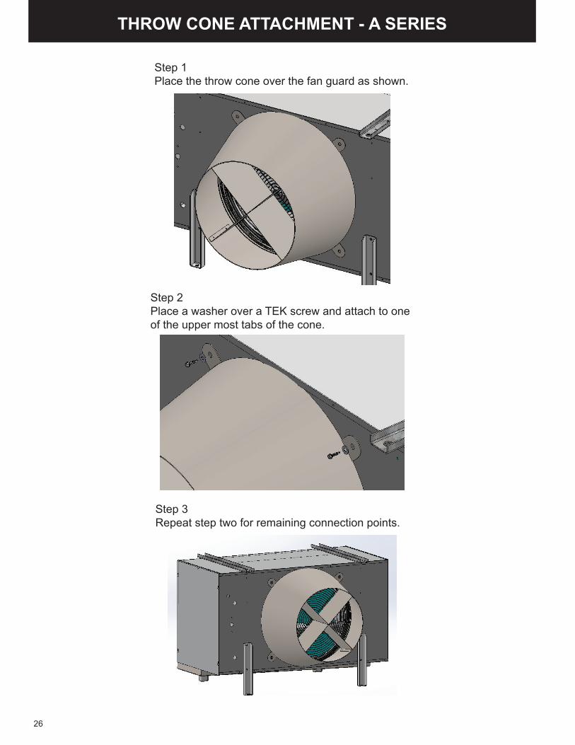
THROW CONE ATTACHMENT - A SERIES
Step 1Place the throw cone over the fan guard as shown.
Step 2Place a washer over a TEK screw and attach to one of the upper most tabs of the cone.
Step 3Repeat step two for remaining connection points.
26

THROW CONE ATTACHMENT - BOC SERIES
Step 1Remove the screws from the fan guard.
Step 2Place the throw cone over the fan guard.
27
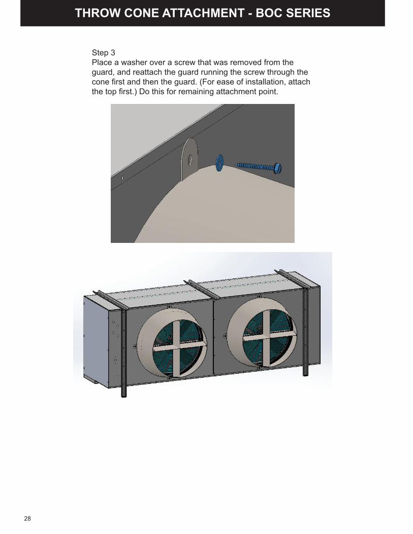
THROW CONE ATTACHMENT - BOC SERIES
Step 3Place a washer over a screw that was removed from the guard, and reattach the guard running the screw through the cone first and then the guard. (For ease of installation, attach the top first.) Do this for remaining attachment point.
28

29

30
31
Bulletin #C-IOM-UC-0418
4492 Hunt St. - Pryor, OK 74361 - (918) 825-7222 - Fax (800) 264-5329
www.century-refrigeration.com
We reserve the right to change or revise specifi cations and product design in connection with any feature of our products.
Such changes do not entitle the buyer to corresponding changes, improvements, additions or replacement for
equipment previously sold or shipped.
ALL CENTURY REFRIGERATION EQUIPMENT MUST BE STARTED AND SERVICED BY QUALIFIED
REFRIGERATION SERVICE PERSONNEL.