Installation, Operation & Maintenance Manual€¦ · Sundyne Centrifugal Pumps Sundyne API pumps...
110
Installation, Operation & Maintenance Manual Sundyne Pumps Model: LMV-801S ` SA-07-11-92, Rev Orig Oct 2015
Transcript of Installation, Operation & Maintenance Manual€¦ · Sundyne Centrifugal Pumps Sundyne API pumps...
Installation, Operation& Maintenance Manual
Sundyne Pumps
Model:LMV-801S
`
SA-07-11-92, Rev OrigOct 2015
http://www.sundyne.com
Copyright
All rights reserved. No part of this publication may be reproduced, stored in a retrieval system or transmitted in any form or by anymeans, electronic, mechanical, photocopying, recording or otherwise without the prior permission of Sundyne LLC.© 2015 Sundyne LLC
Warranty
Sundyne LLC warrants to Buyer for a period of twelve (12) months from the date of being placed in service (but not to exceedeighteen (18) months after the date of shipment) that the equipment at the time of shipment will be free from defects of design,material and workmanship. If any defects or malperformance occur during the warranty period, Sundyne’s sole obligation shall belimited to alteration, repair or replacement at Sundyne’s expense, F.O.B. Factory, of parts or equipment, which upon return toSundyne and upon Sundyne’s examination prove to be defective. Equipment and accessories not manufactured by Sundyne arewarranted only to the extent of and by the original manufacturers’ warranty. Sundyne shall not be liable for damage or wear toequipment caused by abnormal conditions, vibration, failure to properly prime or to operate equipment without flow or caused bycorrosives, abrasives or foreign objects. THE FOREGOING WARRANTY IS EXCLUSIVE AND IN LIEU OF ALL OTHERWARRANTIES, WHETHER EXPRESSED OR IMPLIED INCLUDING ANY WARRANTY OF MERCHANTABILITY OR FITNESSFOR ANY PARTICULAR PURPOSE. In no event shall Sundyne be liable for consequential or incidental damages

Sundyne LLC i http://www.sundyne.comSA-07-11-92, Rev Orig October 2015
EUROPEAN UNION MACHINERY DIRECTIVE(CE Mark System)(where applicable)
This document incorporates information relevant to the Machinery Directive 2006/42/EC. It should beread prior to the use of any of our equipment. Individual maintenance manuals which also conform to theEU Directive should be read when dealing with specific models.
EUROPEAN UNION ATEX DIRECTIVE
This document incorporates information relevant to the ATEX Directive 94/9/EC (Directive on equipment andprotective systems intended for use in potentially explosive atmospheres). It should be read prior to the useof any our equipment.
Compliance to the Directive is based on Atmospheres having pressures ranging from 0.8 to 1.1 bar andtemperatures ranging from –20 C to + 60 C.
As indicated in the ATEX Directive 94/9/EC, It is the responsibility of the user of the pump to indicate to HMDSealless Pumps the Zone and Corresponding group (Dust or Gas) that the pump is to be installed within.
Service
Americas
Sundyne LLC Tel: +1-303-425-080014845 W. 64th Avenue Fax: +1=303-425-0896Arvada, CO 80007 Email: [email protected]
Web: www.sundyne.com
Europe
HMD Sealless Pumps Ltd Tel: +44 (0) 1323 452000Hampden Park Industrial Estate, Fax: +44 (0) 1323 503369Eastbourne Email: [email protected] Sussex Web: www.sundyne.comBN22 9ANEngland
Customer Service 24 Hour 07966 525269

Sundyne LLC ii http://www.sundyne.comSA-07-11-92, Rev Orig October 2015

Sundyne LLC iii http://www.sundyne.comSA-07-11-92, Rev Orig October 2015
Revisions
October 2015 Original Release

Sundyne LLC iv http://www.sundyne.comSA-07-11-92, Rev Orig October 2015
ContentsContents............................................. iv
INTRODUCTION.................................. 1
Sundyne Centrifugal Pumps...........................1
Text Symbols....................................................2Equivalent Terms...........................................3Units...............................................................3
Equipment and Safety Precautions................4Wearing Personal Protective Equipment.......4Lifting .............................................................4Using Forklifts ................................................4Ensuring Electrical Safety..............................5Testing Equipment.........................................5Magnets .........................................................5Using Chemicals ............................................5Protection from Falling...................................5Preventative Machine Guards .......................5
Pre-Commission Checklist..............................6Familiarizing Yourself with the Pump ............6Driver Instructions..........................................6Verifying Auxiliaries .......................................6Checking Driver Rotation...............................6Piping Connections........................................6
General ..............................................................7Application or Use..........................................7
Temperature Classification - (ATEX Directive94/9/EC) .............................................................7
INSTALLATION................................... 9
Inspection .........................................................9
Storing Your Pump Short-Term......................9
Storing Your Pump Long-Term ......................9
Installation Guidelines...................................10Location .......................................................10Foundations .................................................10
Electrical Installation & Grounding ..............11
Suction and Discharge Piping ......................12Pitfalls to Avoid On Suction Pipework .........14
Net Positive Suction Head (NPSH) .............14Discharge Pipework.....................................15
Protection Systems .......................................16Power Control Monitor (PCM) .....................16Temperature Sensor....................................16Differential Pressure Switches ....................16Liquid Sensing Probe ..................................17Secondary Containment or Control .............17VapourView®...............................................17
Precautions ....................................................19Installation Considerations ..........................19
Commissioning ..............................................21General ........................................................21Venting ........................................................21Direction of Rotation ....................................21
START UP ......................................... 22
Start-Up Procedures......................................22Run-In ..........................................................22Start Up .......................................................22
Operating Guidelines ....................................23Precautions..................................................23
Controlling the Pump During Startup..........26Single Operation..........................................26Parallel Operation........................................26
OPERATION & CONTROL................ 27
Operation of Sundyne Pumps ......................27Suction Conditions.......................................27Minimum Flow Conditions ...........................27Entrained Gases..........................................27System Head Curve ....................................27Parallel Operation........................................28
Servicing.........................................................29Maintenance Schedule ................................29Vibration Levels ...........................................29Dismantling..................................................29
Fault Finding ..................................................30Flowcharts ...................................................30
Pump Diagnostics..........................................35
Sundyne LLC v http://www.sundyne.comSA-07-11-92, Rev Orig October 2015
Maintenance ...................................................37General Safety.............................................37Tools Required.............................................38Lifting Points ................................................39
DISASSEMBLY OF PUMP ................ 40
Disassembly - Stage 1 -Removal of Pumpfrom Pipe Work...............................................41
Disassembly - Stage 2 - Motor and MotorSupport (Close Coupled)...............................43
Disassembly - Stage 3 – Magnet Drive Unit 50
Disassembly - Stage 4 – Casing andDiffusers..........................................................62
ASSEMBLY OF PUMP...................... 64
Assembly - Stage 1 – Casing and Diffuser ..65
Assembly - Stage 2 – Magnet Drive Unit .....67
Assembly - Stage 3 – Motor & Motor Support(Close Coupled) .............................................84
Assembly - Stage 4 – Re-Install Pump.........92
REPLACEMENT OF BUSHES &THRUST PAD .................................... 94
Quick Reference Torque Settings ................98
Pump Parts List............................................100
LMV801S Pump Cross Section (NoSecondary Containment) ............................102
Index................................................ 103

Instruction and Operation Manual
SA-07-11-92, Rev Orig 1 October 2015
INTRODUCTION
Sundyne Centrifugal Pumps
Sundyne API pumps provide high-energyperformance and competitive efficiencies in acompact unit that is easy to maintain. Sundynepumps are single stage and are closely coupled(OH4). Designed to increase the pressure of acontinuous flow of fluid by applying centrifugalaction, Sundyne pumps are most commonlyused in HPI, CPI, and Boiler Feed applications.Commonly applied in refineries, petrochemicalplants, and power generation plants, Sundynepumps are used in high-head, low-to-mediumflow processes.
This manual presents installation, servicing,troubleshooting, maintenance, and spare partsinformation for the latest Sundyne LMV 801Scentrifugal pump. It is important that the manualis read thoroughly before installing andoperating the pump. Images provided in thismanual are based on typical configurations.Refer to the drawings provided with the order forthe actual configuration. Questions regardingparts, service or operation should be directed to
your Authorized Service Center or a listedSundyne location.
Note: Parenthetical numbers included in thetext correspond to item numbers on theillustrated figures. The item numberserves as a location identifier and not apart number. The correct spare partcan be ordered referencing the itemand serial numbers. From there thecorrect part number can be obtained.
Whilst every care is taken to ensure that theinformation is correct, no liability can beaccepted by Sundyne or HMD Sealless Pumpsfor loss, damage or injury caused by errors in oromission from the information given.
Sundyne LLC RESERVES THE RIGHT TOCHANGE THEIR RECOMMENDATIONSWITHOUT PRIOR NOTICE ORCONSULTATION.

Instruction and Operation Manual
SA-07-11-92, Rev Orig 2 October 2015
Text Symbols
In accordance with general safety and handling,OSHA 1910.145, BS EN 809 and other localdirectives, the following warning symbols andsigns are used in this manual.
DANGER: Text accompanied by thissymbol indicates failure to avoid hazardsidentified with this symbol will result indeath.
WARNING: Text accompanied by thissymbol indicates that failure to recognizethese hazards could result in injury oreven death.
ELECTRICAL HAZARD: Textaccompanied by this symbol indicatesthat failure to follow directions couldresult in electrical damage to equipmentor electrical shock.
RECOMMENDED: Text accompanied bythis symbol indicates recommendedusage.
REMINDER: Text accompanied by thissymbol indicates a reminder to performan action.
EQUIPMENT USE ALERT: Textaccompanied by this symbol indicatesthat failure to follow directions couldresult in damage to equipment.
RECOMMENDED TOOL: Textaccompanied by this symbol identifiesthe tool required for the operation.

Instruction and Operation Manual
SA-07-11-92, Rev Orig 3 October 2015
To assist in global understanding the following equivalent terminology is used: -
Used in this manual Also known as
Alignment Pad Support Gasket
Bush Radial Bearing or Journal Bearing
Bearing Assembly Power Frame
Containment Shell Shroud
Gasket Joint
Spanner Wrench
Fit Install
Grounding Earthing
Check Valve Non Return Valve
Both Metric and equivalent US units are shown in this manual where appropriate.
Conversion factors between units are: -
°C to °F multiply by 1.8 and add 32
mm to inches divide by 25.4
Nm to lbf-ft divide by 1.356
ml to US Fl.oz divide by 29.6
Equivalent Terms
Units
Instruction and Operation Manual
SA-07-11-92, Rev Orig 4 October 2015
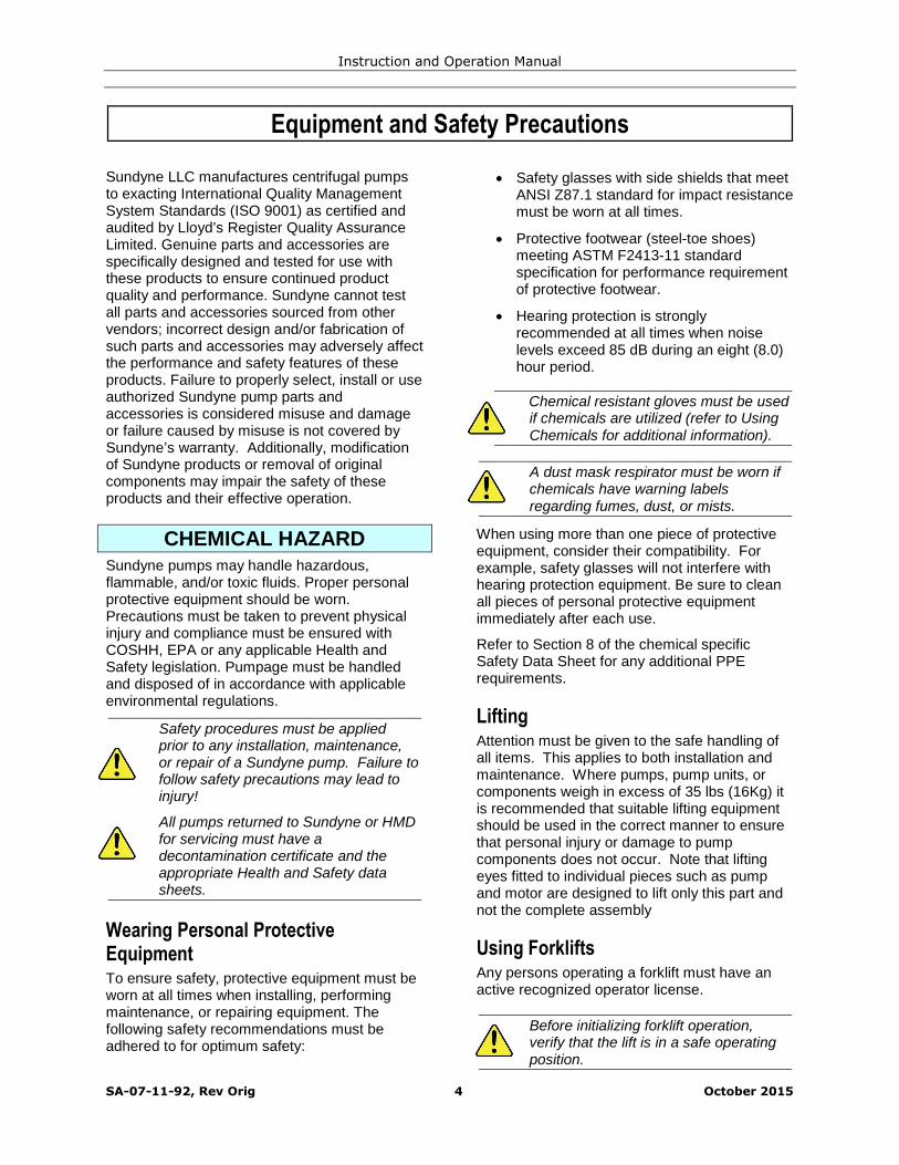
Equipment and Safety Precautions
Sundyne LLC manufactures centrifugal pumpsto exacting International Quality ManagementSystem Standards (ISO 9001) as certified andaudited by Lloyd’s Register Quality AssuranceLimited. Genuine parts and accessories arespecifically designed and tested for use withthese products to ensure continued productquality and performance. Sundyne cannot testall parts and accessories sourced from othervendors; incorrect design and/or fabrication ofsuch parts and accessories may adversely affectthe performance and safety features of theseproducts. Failure to properly select, install or useauthorized Sundyne pump parts andaccessories is considered misuse and damageor failure caused by misuse is not covered bySundyne’s warranty. Additionally, modificationof Sundyne products or removal of originalcomponents may impair the safety of theseproducts and their effective operation.
CHEMICAL HAZARDSundyne pumps may handle hazardous,flammable, and/or toxic fluids. Proper personalprotective equipment should be worn.Precautions must be taken to prevent physicalinjury and compliance must be ensured withCOSHH, EPA or any applicable Health andSafety legislation. Pumpage must be handledand disposed of in accordance with applicableenvironmental regulations.
Safety procedures must be appliedprior to any installation, maintenance,or repair of a Sundyne pump. Failure tofollow safety precautions may lead toinjury!
All pumps returned to Sundyne or HMDfor servicing must have adecontamination certificate and theappropriate Health and Safety datasheets.
Wearing Personal ProtectiveEquipmentTo ensure safety, protective equipment must beworn at all times when installing, performingmaintenance, or repairing equipment. Thefollowing safety recommendations must beadhered to for optimum safety:
Safety glasses with side shields that meetANSI Z87.1 standard for impact resistancemust be worn at all times.
Protective footwear (steel-toe shoes)meeting ASTM F2413-11 standardspecification for performance requirementof protective footwear.
Hearing protection is stronglyrecommended at all times when noiselevels exceed 85 dB during an eight (8.0)hour period.
Chemical resistant gloves must be usedif chemicals are utilized (refer to UsingChemicals for additional information).
A dust mask respirator must be worn ifchemicals have warning labelsregarding fumes, dust, or mists.
When using more than one piece of protectiveequipment, consider their compatibility. Forexample, safety glasses will not interfere withhearing protection equipment. Be sure to cleanall pieces of personal protective equipmentimmediately after each use.
Refer to Section 8 of the chemical specificSafety Data Sheet for any additional PPErequirements.
LiftingAttention must be given to the safe handling ofall items. This applies to both installation andmaintenance. Where pumps, pump units, orcomponents weigh in excess of 35 lbs (16Kg) itis recommended that suitable lifting equipmentshould be used in the correct manner to ensurethat personal injury or damage to pumpcomponents does not occur. Note that liftingeyes fitted to individual pieces such as pumpand motor are designed to lift only this part andnot the complete assembly
Using ForkliftsAny persons operating a forklift must have anactive recognized operator license.
Before initializing forklift operation,verify that the lift is in a safe operatingposition.
Instruction and Operation Manual
SA-07-11-92, Rev Orig 5 October 2015
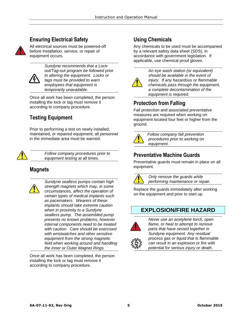
Ensuring Electrical SafetyAll electrical sources must be powered-offbefore installation, service, or repair ofequipment occurs.
Sundyne recommends that a Lock-out/Tag-out program be followed priorto altering the equipment. Locks ortags must be provided to warnemployees that equipment istemporarily unavailable.
Once all work has been completed, the personinstalling the lock or tag must remove itaccording to company procedure.
Testing Equipment
Prior to performing a test on newly installed,maintained, or repaired equipment; all personnelin the immediate area must be warned.
Follow company procedures prior toequipment testing at all times.
Magnets
Sundyne sealless pumps contain highstrength magnets which may, in somecircumstances, affect the operation ofcertain types of medical implants suchas pacemakers. Wearers of theseimplants should take extreme cautionwhen in proximity to a Sundynesealless pump. The assembled pumppresents no known problems, howeverinternal components need to be treatedwith caution. Care should be exercisedwith wristwatches and other sensitiveequipment from the strong magneticfield when working around and handlingthe Inner or Outer Magnet Rings.
Once all work has been completed, the personinstalling the lock or tag must remove itaccording to company procedure.
Using ChemicalsAny chemicals to be used must be accompaniedby a relevant safety data sheet (SDS), inaccordance with government legislation. Ifapplicable, use chemical proof gloves.
An eye wash station (or equivalent)should be available in the event ofinjury. If any hazardous or flammablechemicals pass through the equipment,a complete decontamination of theequipment is required.
Protection from FallingFall protection and associated preventativemeasures are required when working onequipment located four feet or higher from theground.
Follow company fall preventionprocedures prior to working onequipment.
Preventative Machine GuardsPreventative guards must remain in place on allequipment.
Only remove the guards whileperforming maintenance or repair.
Replace the guards immediately after workingon the equipment and prior to start up.
EXPLOSION/FIRE HAZARD
Never use an acetylene torch, openflame, or heat to attempt to removeparts that have seized together inSundyne equipment. Any residualprocess gas or liquid that is flammablecan result in an explosion or fire withpotential for serious injury or death.

Instruction and Operation Manual
SA-07-11-92, Rev Orig 6 October 2015
Pre-Commission Checklist
Familiarizing Yourself with the PumpBefore servicing and starting up the Sundynepump, carefully review all information on theproduct, including:
Specification sheets
Outline drawings
Performance curves
Instruction and related manuals
System P&ID/Process Flow Diagram(Clients equipment)
Control system and operationalphilosophy/narrative (Client)
Familiarize yourself with the pump configurationbefore starting and operating the pump.
Driver InstructionsCarefully follow all installation and startinginstructions provided by the driver manufacturer.This information is included in the final datapackage.
Verifying AuxiliariesBefore start up, verify that the followingauxiliaries are met:
Check the utility connections
Verify that the auxiliary piping conformsto Sundyne standards, as indicated inthe detailed specifications
Verify all switch and instrumentconnections
Verify that all switch and instrumentsettings are set to normal operatingstandards
Calibrate all measurement equipment,such as flow meters, ampere meters,and pressure meters, etc.
Checking Driver RotationVerify that the direction of the driver rotates inthe same direction as the arrow stamped or caston the pump casing.
Do not run pump dry
Piping ConnectionsVerify that the following bolted or threadedconnections are tight:
Pump flange bolts
Is a check valve in the discharge line?
Note: A start-up bypass line upstream ofthe check valve is recommendedwhenever feasible
Looking down
Rotation of the driver must be counter-clockwise.
View Looking Down
Impeller and DriverShaft Rotation
Vent
Three InchSuction
Two InchDischarge
Instruction and Operation Manual
SA-07-11-92, Rev Orig 7 October 2015
General
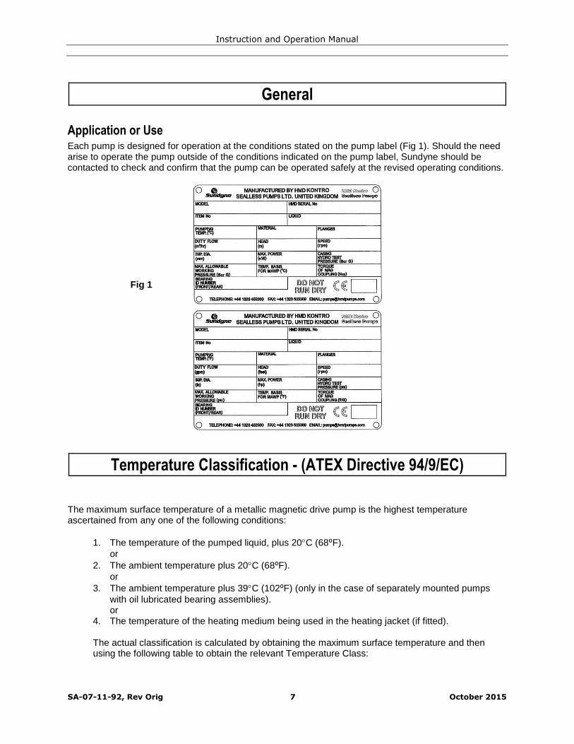
Application or UseEach pump is designed for operation at the conditions stated on the pump label (Fig 1). Should the needarise to operate the pump outside of the conditions indicated on the pump label, Sundyne should becontacted to check and confirm that the pump can be operated safely at the revised operating conditions.
Temperature Classification - (ATEX Directive 94/9/EC)
The maximum surface temperature of a metallic magnetic drive pump is the highest temperatureascertained from any one of the following conditions:
1. The temperature of the pumped liquid, plus 20C (68⁰F).or
2. The ambient temperature plus 20C (68⁰F).or
3. The ambient temperature plus 39C (102⁰F) (only in the case of separately mounted pumpswith oil lubricated bearing assemblies).or
4. The temperature of the heating medium being used in the heating jacket (if fitted).
The actual classification is calculated by obtaining the maximum surface temperature and thenusing the following table to obtain the relevant Temperature Class:
Fig 1

Instruction and Operation Manual
SA-07-11-92, Rev Orig 8 October 2015
Table 1
TemperatureClass
Maximum SurfaceTemperature (C)
Maximum SurfaceTemperature (F)
T1 450 842
T2 300 572
T3 200 392
T4 135 275
T5 100 212
T6 85 185
Example:The pump is pumping a liquid with a temperature of 120C (248⁰F). The pump is close coupledand therefore does not have an external oil lubricated bearings. The maximum ambienttemperature in which the pump may operate is 30C (86⁰F)
Condition 1 equates to 120C + 20C = 140C (284⁰F).
Condition 2 equates to 30C + 20C = 50C (122⁰F).Condition 3 does not apply.Condition 4 does not apply.
Thus the maximum surface temperature of the pump is 140C which equates to a temperatureclassification of T3.
The maximum surface temperature of a plastic lined non-metallic magnetic drive pump or aZeroLoss shell pump is the highest temperature ascertained from any one of the followingconditions:
1. The temperature of the pumped liquid, plus 10C (50⁰F).or
2. The ambient temperature plus 10C (50⁰F).or
3. The ambient temperature plus 39C (102⁰F)(only in the case of separately mounted pumpswith oil lubricated bearing assemblies).

Instruction and Operation Manual
SA-07-11-92, Rev Orig 9 October 2015
INSTALLATION
Inspection
Inspect the shipping container for any damagesustained during shipment. If damage is found,note the nature and extent before unpacking. Aphotograph is helpful in any claims to be madeagainst the shipper; also, inform Sundyne or thelocal authorized distributor. Check thenameplate data against the shipping papers andagainst your purchase order to ensure that thecorrect pump is supplied.
After unpacking check to see that the suctionand discharge flanges are sealed. If the sealshave come loose, examine the pump to ensureno packing material or dirt is in the casing. Itmay be necessary to remove the pump casing tocheck. Refer to the Dismantling Instructions ifrequired.
Inspect the suction and discharge flanges to becertain that they are free from scratches or nicksand that they are clean. The gasket seatingsurfaces in particular should be cleanedcarefully.
Ensure that a copy of this manual is in the handsof the installation personnel and that they haveread it thoroughly before proceeding further.
The input shaft on the pump should turnfreely on the pump, however it shouldnot be turned excessively when thepump is dry. Excessive rotation of theshaft when the pump is dry may resultin damage to the bearings. If the inputshaft does turn freely, and if rotation is“not smooth,” damage may haveoccurred during shipping.
Storing Your Pump Short-Term
If your Sundyne pump is not to be installedimmediately but within the next 6 months,protect it from exposure to moisture and dust.The pump should be left undisturbed in itstransportation packaging and stored in a dryarea and not subjected to vibration.If removal from the packaging is necessary, thepump should be stored covered in a clean, dry
area protected from physical damage andvibration. All flanged and threaded connectionsshould remain capped.
Note: Observe the storage instructionsprovided by the driver manufacturer.
Storing Your Pump Long-Term
In addition to the precautions in the short-termsection above, additional precautions arerequired for long-term storage.
If your Sundyne pump will not be operated for aperiod of time exceeding six months from thedate of shipment, long-term storage conditionsmust be met. Sundyne should be informed at
the time of order that long term storage isanticipated so that special packagingarrangements can be made. These will consistof:
The pump will be packed in a woodencrate.
The pump will be packed with bags ofsilica gel and covered with tar paper.

Instruction and Operation Manual
SA-07-11-92, Rev Orig 10 October 2015
All machined surfaces will be greased (ifappropriate).
All flanges and threaded connectionswill be capped.
It is recommended that the pump should be leftin its transportation packaging and stored in adry area and not subjected to any vibration,which may cause brinelling of the electricalmotor and pump bearings. At suitable intervals,during a period of storage, the pump rotorshould be turned by hand.After long term storage, when the pump isinstalled, the grease and oil lubricated
assemblies should have the lubricants cleanedout and replaced. Refer to the section 7.2.1 forfurther details. This precaution is necessarybecause lubricants can deteriorate after a periodof time.Prior to installation it is recommended that thepump is inspected by a Sundyne engineer andthat the commissioning is similarly supervised.
Note: Sundyne does not accept liability forequipment damaged during the storageperiod. Sundyne does not guaranteethe quality of equipment during andafter the storage period.
Note: Any inspection fees are the soleresponsibility of the purchaser.
Installation Guidelines
LocationCentrifugal pumps should be installed as closeas is practical to the source of liquid supply andpreferably below the liquid level in the supplyvessel.
Pumps installed on systems requiring suctionlifts need special consideration and Sundyneshould be consulted.
Pump units must be installed to ensure thatadequate space is available for access andmaintenance.
Sundyne supplies certified drawings showingfoundation details and the space necessary tocarry out routine inspection and maintenancewith every pump; extra drawings are available ata moderate cost on request.
FoundationsFoundations may consist of any structure heavyenough to afford permanent rigid support to thefull area of the pump base and to absorb anynormal strains or shock. Concrete foundationsbuilt up from solid ground are the mostsatisfactory.
The pump base in the case of close coupled, orthe base plate in the case of separately mountedpumps should be bolted securely in position withsuitable foundation bolts.
When a pump unit is mounted on steelwork orother such structures, care must be taken toensure that the baseplate is not subject todistortion or vibration.
Where possible the pump units should bemounted over or as near as possible to mainsupporting members.
It may be necessary to mount pump unitsresiliently if there is the possibility of excessvibration. If in doubt, contact Sundyne or theauthorized distributor.
Misalignment should be corrected by shims.Grouting may be necessary to preventmovement of the pump and stop theaccumulation of chemical or hydrocarbon underthe pump base. The pump should be leveled byshimming under the base prior to grouting thechannels that are to be filled with grout throughthe access holes. The nuts on the foundationbolts should not be tightened until the grout hasset for at least 48 hours. Fig. 2.
Recommended Long-Term StorageProcedures

Instruction and Operation Manual
SA-07-11-92, Rev Orig 11 October 2015
Electrical Installation & Grounding
Electrical connection of the pump motor, to a suitably rated power supply shall be carried out byelectrically skilled persons or staff. Care should be taken to ensure that the motor electrical connectionwill not overload the power supply. Provision shall be made to enable electrical isolation of theequipment.
Pumps that have been supplied in accordance to the ATEX Directive (94/9/EC) will be identified by alabel with the following symbol on it:
Such units are supplied with an M8 grounding stud, saddle washer, shake-proof washer and locking nutlocated on the Coupling Housing (Item 43.43). Once the unit has been installed and levelled, this shall bewired to ground with a suitable grounding cable, Fig 3, by electrically skilled persons or staff.
To further protect the integrity of the unit, an additional grounding connection can be made to the motor.
Fig. 3 Typical GroundingArrangement via M8Grounding Stud
Fig. 2

Instruction and Operation Manual
SA-07-11-92, Rev Orig 12 October 2015
Suction and Discharge Piping
Good practice dictates that there should be a minimum straight length of pipe on the suction flange of thepump equal to ten times the suction pipe diameter. This is to allow the liquid to flow into the pump casingwithout turbulence. (Fig. 4)
In addition, it is also good practice to use suction pipeline at least one to two sizes larger than the pumpnozzle and reduce the pipe diameter at the pump flange. When doing so, insure the eccentric reducer isinstalled as shown with sloped side facing down (Fig. 4).
Ensure that the inside diameter of the suction pipe matches the nozzle openings as accurately aspossible in order not to strain the pump casing. On no account lever the suction pipe flange to align it tothe pump suction nozzle flange. The flange bolts should slip in to the aligned flange holes withoutstraining the pipework.
Apply proper support to suction and discharge piping with proprietary pipe hangers or supports to keepthe strain off the pump casing. (Fig. 5)
10 x Pipe Minimum
Fig. 4
Fig. 5
EccentricReducer

Instruction and Operation Manual
SA-07-11-92, Rev Orig 13 October 2015
Ensure that all joints in the suction pipework are airtight.
Install suction piping, elbows, eccentric reducers (flat side up as in Fig 6) and all other fittings so that noair pockets can be created within the suction system.
Position of eccentric reducer when liquid is below pump centerline. (Fig. 6)
Position of eccentric reducer when liquid is above pump centerline. (Fig. 7)
Mount valves from the suction pipework with the stems horizontal or vertically down to avoid air pockets.(Fig. 8)
10 x Pipe Minimum
Fig. 6
10 x Pipe Minimum
Fig. 7
10 x Pipe Minimum
Fig. 8

Instruction and Operation Manual
SA-07-11-92, Rev Orig 14 October 2015
Pitfalls to Avoid On Suction PipeworkAvoid the use of valves that have high friction loss.
Avoid the use of in-line filters (with the exception of the commissioning period)
Avoid pipework layouts that promote vortices at the liquid level in the supply vessel.
Avoid the use of multiple spring type check valves.
Avoid flow meters.
Avoid at all costs a pipework system that may allow the pump to run dry.
Avoid using more than one pump feeding at the same time from a common suction pipeline.
Avoid any operating conditions that reduce the NET POSITIVE SUCTION HEAD (See section coveringNPSH).
Net Positive Suction Head (NPSH)
Liquids cannot be towed or dragged down a pipe; liquids can only be pushed along a pipe. The push theliquid needs to flow in to the pump can only be supplied by some external energy source such as theabsolute pressure in the surface of the liquid in the vessel and the head of the liquid over the center lineof the pump.
A system that has insufficient NPSH available will cause the pump to cavitate. The general effects ofcavitation are noise, erosion of metal surfaces and vibration of the system. The latter situation will resultin the magnetic coupling overheating and the product-lubricated bearings will wear rapidly. Cavitationstarts when the pressure at the pump suction falls near to the value of the vapor pressure of the pumpliquid and this varies with temperature.
At the time the pump is selected, the NPSH available will have been calculated as per the followingmethod: -
NSPH available = Ps-Vp+Hs+Vs-HfWhere:Ps = Absolute pressure in suction vesselVp = Vapour pressure of liquidHs = Total static headHf = Friction losses in suction line
Vs = Velocity Head =G
V
2
2
In the above equation, all parameters must be converted to meters head of liquid before the liquidcalculation is carried out. The pump should be selected so that the NPSH available is a minimum of 0.5m(1.6 ft) greater than the NPSH required by the pump.
No subsequent alteration should be made to the pipework system without considering the effect that it willhave on the NPSH available.
Fig. 9
Hs
Hf
Ps
Vp
Instruction and Operation Manual
SA-07-11-92, Rev Orig 15 October 2015
Discharge PipeworkThe discharge pipework and its related equipment does not normally have as great an influence on pumpperformance as the suction pipework. There are, however, some points to watch with discharge pipeworkto ensure efficient pump operation.
In a manner similar to the suction pipework, provision must be made to support the discharge pipeworkand any other equipment.
The discharge pipework is normally more extensive than the suction system, so there are increasedamounts of pipe strain being transferred to the pump and this must be avoided.
Where possible, there should be a straight length of pipe immediately on the discharge nozzle followed bya suitable valve and between the valve and the discharge flange there should be a pressure gauge tohelp monitor the pump's performance.
Should a check valve be fitted in the pump discharge line, provision should be made to vent the spacebetween the pump and the check valve or the pump will not prime.
It cannot be stressed enough, how important it is to have pressure gauges on both the suction and thedischarge sides of the pump.
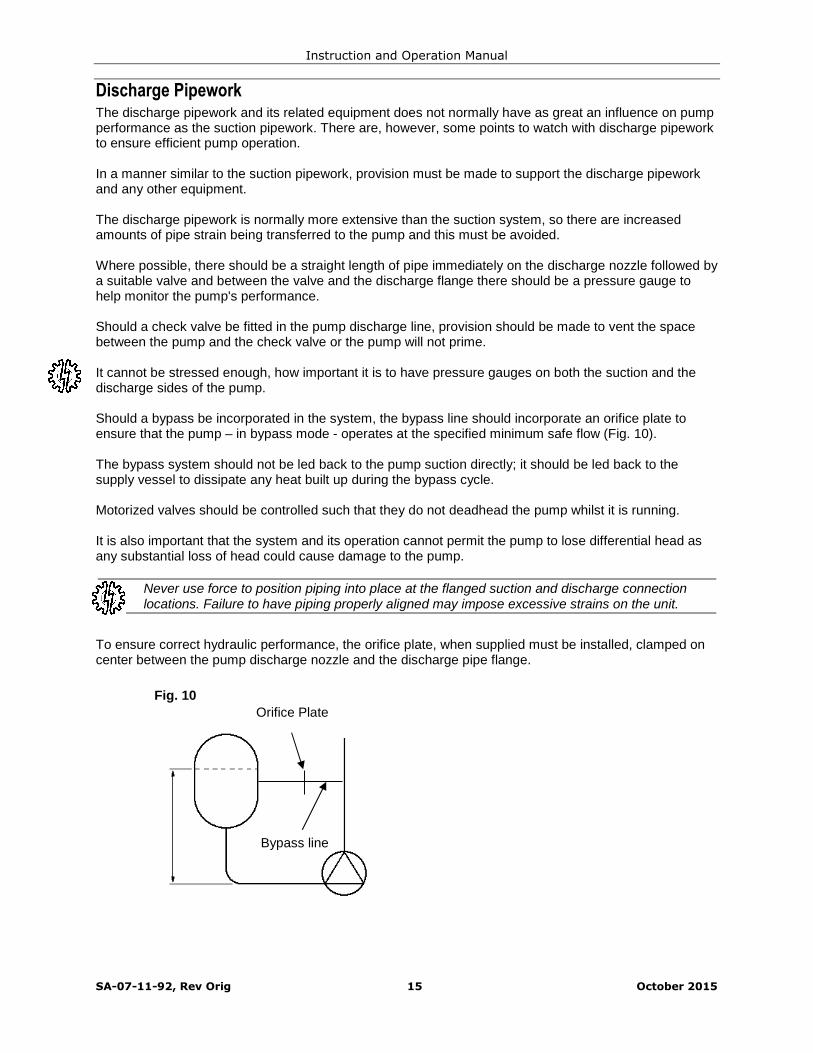
Should a bypass be incorporated in the system, the bypass line should incorporate an orifice plate toensure that the pump – in bypass mode - operates at the specified minimum safe flow (Fig. 10).
The bypass system should not be led back to the pump suction directly; it should be led back to thesupply vessel to dissipate any heat built up during the bypass cycle.
Motorized valves should be controlled such that they do not deadhead the pump whilst it is running.
It is also important that the system and its operation cannot permit the pump to lose differential head asany substantial loss of head could cause damage to the pump.
Never use force to position piping into place at the flanged suction and discharge connectionlocations. Failure to have piping properly aligned may impose excessive strains on the unit.
To ensure correct hydraulic performance, the orifice plate, when supplied must be installed, clamped oncenter between the pump discharge nozzle and the discharge pipe flange.
Bypass line
Fig. 10
Orifice Plate
Instruction and Operation Manual
SA-07-11-92, Rev Orig 16 October 2015
Protection Systems
To minimize the effect of process or system malfunction the LMV 801S Sealless Pump can be providedwith various fail safe devices to increase plant security.
The type of instrumentation or safety devices offered depends on the properties of the process liquid, theapplication and plant operating procedures.
It is rare, that all of the protection methods illustrated are needed and the number or type of protectivedevice fitted is often a matter of client experience and preference.
Power Control Monitor (PCM)Protects Against
Dry Running Pump Seizure Cavitation Motor Faults Closed Valve
Motor power monitoring can provide good pump protection against low flow or dry running. Being remotefrom the pump head the power sensor is not affected by the liquid handled and is, therefore, more reliablethan differential pressure or flow switches.
Temperature SensorProtects Against
Dry Running Closed Head and Minimum Flow Internal/External Bearing Wear Pump Seizure Severe Cavitation Process Overheating
The containment shell provides pressure retention of the liquid cooling the pump bearings. Thetemperature sensor monitors the temperature of the outside diameter of the containment shell detectingtemperature movements in response to operational change. The temperature sensing device, therefore,provides an optimum, inexpensive form of continuous pump protection. Normally an over temperature cutout and/or alarm is required, but low and high trips can be provided for liquids which can freeze atambient air temperatures.
Differential Pressure SwitchesProtects Against
Dry running Minimum/Maximum Flow and Closed Head Severe Cavitation Pump Seizure
It is essential that sealless pumps are not run dry otherwise rapid bearing wear and heat buildup willoccur. Differential pressure switches are reliable and economic forms of dry running protection. Thesefailsafe devices are particularly suited to applications where the risk of suction starvation is high. Theswitch contacts are wired into the motor control circuit to provide a pump cut-out in the event of a drop inpump differential pressure.

Instruction and Operation Manual
SA-07-11-92, Rev Orig 17 October 2015
Liquid Sensing ProbeProtects Against
Internal Liquid Leakage Starting the pump dry
This instrumentation is usually installed in conjunction with a pressure tight coupling housing. An earlywarning of internal leakage is given before dangerous quantities of spillage can fill the housing. Anotheruse for the liquid sensing probe is to ensure that the pump is primed with liquid before it can be started.When used for this, the liquid sensing probe is mounted at the pump discharge flange.
Secondary Containment or ControlProtects Against
Leakage to Atmosphere Hazardous Emissions
Where a requirement for secondary containment or control exists, a sealed coupling housing is used toprovide secondary pressure retention, to contain or control fluid leakage. The sealed coupling housing ispressure tested to the same hydraulic pressure rating as the pump liquid end. The drive shaft is fitted witha sealing system to suit.
The sealed coupling housing can be configured with optional flanged, top vent and drain vent ports toenable connection to different sensors and to enable the safe disposal and flushing of a system, in theunlikely event of a primary containment breach.Although not always required, the pressure tight housing is desirable for very toxic or flammablechemicals.
The sealed coupling housing can be specified with a variety of sensors, varying in sensitivity from; theLiquid Sensing Probe (refer to previous section), a pressure switch or a gas or vapor detector. Thesesensors along with the shaft sealing system are configured to either prevent or limit any liquid or vaporescaping the primary pressure boundary from entering the power frame and its bearings.
If you require further information on secondary containment or control options, or pump protection devicesplease contact Sundyne/HMD or your local agent.
VapourView®Protects Against
Dry Running Gas or Vapour Related Process Upsets Gas in System or Vapourisation Pump Seizure
VapourView® is a patent protected instrument that sits outside the primary pressure boundary and usesultrasonic technology to monitor the presence of gas or vapour in the containment shell. In addition toprotecting the operation of the magnetic drive pump the VapourView® instrument provides vitalinformation to an end-user on the condition of the process liquid.
It is strongly recommended, that as a minimum, power sensing protection with a Power ControlMonitor is used to ensure long and safe operation of your sealless pump. This is particularlyrelevant to pumps being used in potentially explosive atmospheres.
For guidance on the availability of protection systems for a specific pump range, please refer to Fig. 11and Table 2.
If you have a specific requirement, contact Sundyne/HMD to discuss the available options in more detail.

Instruction and Operation Manual
SA-07-11-92, Rev Orig 18 October 2015
Table 2: Availability of Instrumentation
Model Prefix PowerControlMonitor
TemperatureSensingDevice
DifferentialPressureSwitches1
PressureTightCouplingHousing
LiquidSensingProbe
SecondaryContainmentor Control
VapourView
LMV 801S
Note: Any instrumentation installed in a Potentially Explosive Atmosphere should be ATEX certified.
1 In some cases the connection of DP switch is made into suction and discharge piping and not the pump casing.
Fig. 11: Protection Systems (Typical)
DifferentialPressure (DP)Switch
PowerControlMonitor
LiquidLevelProbe
TemperatureSensingDevice
VapourView
Instruction and Operation Manual
SA-07-11-92, Rev Orig 19 October 2015
Precautions
Installation ConsiderationsA significant proportion of all pump problems occur during the commissioning period. There are a numberof reasons for these problems and usually they are not as a result of poor materials, bad workmanship ordesign of the pump.
Normally, the problems encountered during commissioning are due to:
Debris left in the system during the construction period Unexpected system characteristics Incorrect pump selection
Every effort should be made to ensure that debris is removed from the pipework and related equipmentprior to installing the pump.
The pump should not be installed until all pipework has been flushed to remove washers, nuts, weldingslag, welding rod, studs, pieces of gasket material, pieces of rag, shot etc.
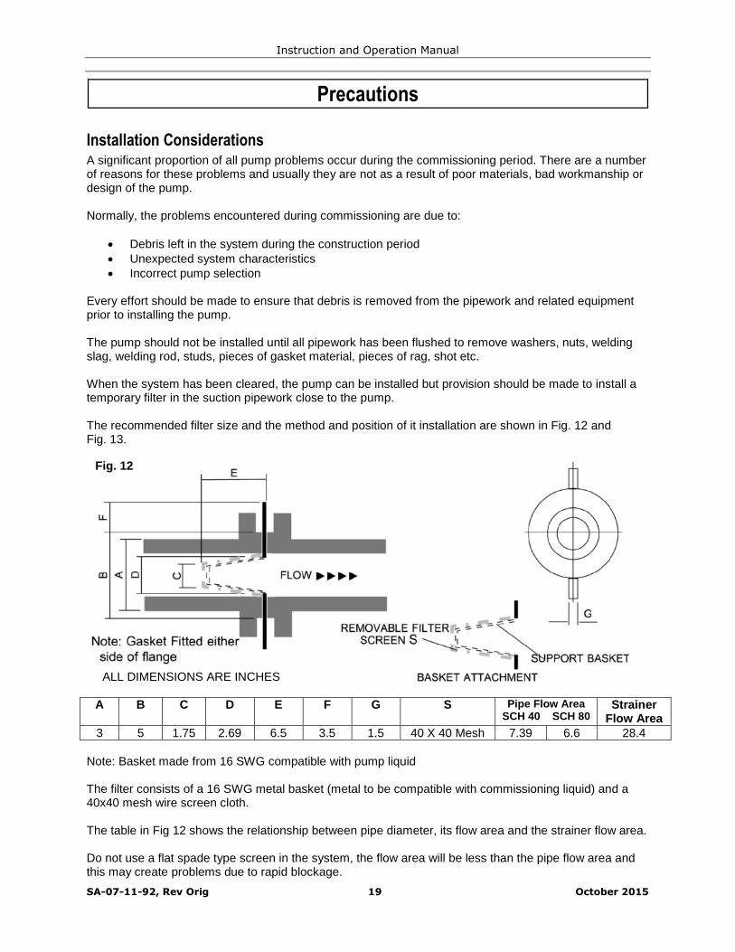
When the system has been cleared, the pump can be installed but provision should be made to install atemporary filter in the suction pipework close to the pump.
The recommended filter size and the method and position of it installation are shown in Fig. 12 andFig. 13.
A B C D E F G S Pipe Flow AreaSCH 40 SCH 80
StrainerFlow Area
3 5 1.75 2.69 6.5 3.5 1.5 40 X 40 Mesh 7.39 6.6 28.4
Note: Basket made from 16 SWG compatible with pump liquid
The filter consists of a 16 SWG metal basket (metal to be compatible with commissioning liquid) and a40x40 mesh wire screen cloth.
The table in Fig 12 shows the relationship between pipe diameter, its flow area and the strainer flow area.
Do not use a flat spade type screen in the system, the flow area will be less than the pipe flow area andthis may create problems due to rapid blockage.
Fig. 12
ALL DIMENSIONS ARE INCHES

Instruction and Operation Manual
SA-07-11-92, Rev Orig 20 October 2015
Fig. 13 shows how the temporary filter is installed in the system. It is important that all the gauges (PG1,PG2 and PG3) are installed; PG2 and PG3 will indicate if the filter is blocking and PG2 and PG1 willmonitor the differential head across the pump to check that the pump is achieving duty.
After commissioning, gauges PG1 and PG2 should be installed permanently as they afford excellentcontinuing checks on the pump’s performance.
The gauges should be calibrated in the same units and measure absolute pressure.
All pipework and related equipment should be checked to ensure it is installed correctly and is leak free.
Fig. 13. Pressure Gage and Temporary FilterInstallation
PG3 PG2 PG1
TemporaryFilter

Instruction and Operation Manual
SA-07-11-92, Rev Orig 21 October 2015
Commissioning
GeneralThe LMV-801S pump is a vertical in-line typepumps and is normally close coupled to thedrive motor. Prior to initial start-up, specialattention must be given to both checking thedirection of rotation and to venting any trappedair from the pumps.
The LMV-801S pump must never be run againsta closed discharge valve.
VentingPurposeInternal rotating parts are supported by plainbearings that are lubricated with the liquid beingpumped. It is imperative that all internal bearingsare immersed in the pumped liquid before thepump is run for the first time after installation ormaintenance. Proper venting of the pump willensure all bearings are flooded and ready forstart-up.
MethodThe following method for venting can be usedfor the LMV-801S pumps.
Open both suction and discharge lines toflood pump
Wait 5 minutes Open the vent line to purge air, close vent
line Wait 5 minutes
Open vent line a second time to purgeremaining air, close vent line
Pump is now ready for direction of rotationcheck.
On pump startup, check that dischargehead is within expected operating range. Ifdischarge head is lower than expected, ventpump once more.
Direction of RotationEnsure pump is full of liquid prior to checkingdirection of rotation – Never run the pump dry,even briefly to check rotation.
Fill pump with liquid and vent as above Connect motor terminals to power supply Remove motor cowl to observe motor fan Check direction of rotation labelling on pump Briefly energize motor to check direction is
correct If direction is wrong, swap over two phases
on the terminal block Re-check direction Replace motor cowl
Pump is now ready for start-up providing theproper venting procedure has been carried out.Refer to section for Pump Operation.
Instruction and Operation Manual
SA-07-11-92, Rev Orig 22 October 2015
START UPStart-Up Procedures
Run-InIf the pump is to be run under conditions whichare considerably different from those conditionslisted on the spec sheet (such as a change inspecific gravity, suction pressure, flow rate, etc.)the factory should be consulted to ensure thatthe run-in conditions are compatible with thepump.
Start UpClose all drains; open the suction and dischargevalves fully and allow the pump to fill with liquid.Open the vent line and allow gas to ventappropriately, prior to starting the pump. Allowpump to vent until all gas has escaped and onlyliquid flows. Refer to the section Venting for therecommended procedure.
Do not energize the motor until the pump hasbeen completely filled with liquid.
Check that the motor rotates in the samedirection as the indicating arrow.
!! WARNING !! Under NO circumstancesshould the pump be run in the reversedirection!!
Close down the discharge valve so that it isabout one quarter open. This is done to preventexcessive loading of the pump or driver whenstarting.
The LMV-801S pump must never be runagainst a closed discharge valve.
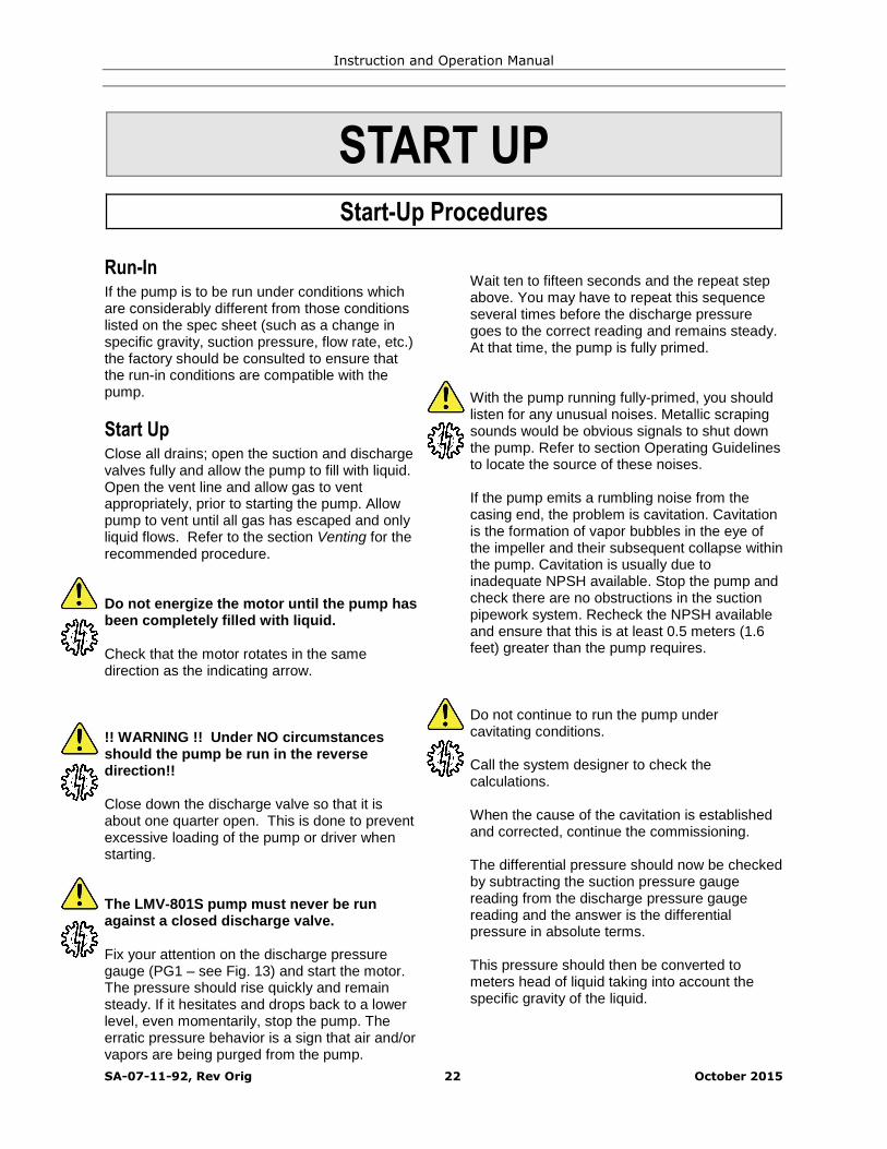
Fix your attention on the discharge pressuregauge (PG1 – see Fig. 13) and start the motor.The pressure should rise quickly and remainsteady. If it hesitates and drops back to a lowerlevel, even momentarily, stop the pump. Theerratic pressure behavior is a sign that air and/orvapors are being purged from the pump.
Wait ten to fifteen seconds and the repeat stepabove. You may have to repeat this sequenceseveral times before the discharge pressuregoes to the correct reading and remains steady.At that time, the pump is fully primed.
With the pump running fully-primed, you shouldlisten for any unusual noises. Metallic scrapingsounds would be obvious signals to shut downthe pump. Refer to section Operating Guidelinesto locate the source of these noises.
If the pump emits a rumbling noise from thecasing end, the problem is cavitation. Cavitationis the formation of vapor bubbles in the eye ofthe impeller and their subsequent collapse withinthe pump. Cavitation is usually due toinadequate NPSH available. Stop the pump andcheck there are no obstructions in the suctionpipework system. Recheck the NPSH availableand ensure that this is at least 0.5 meters (1.6feet) greater than the pump requires.
Do not continue to run the pump undercavitating conditions.
Call the system designer to check thecalculations.
When the cause of the cavitation is establishedand corrected, continue the commissioning.
The differential pressure should now be checkedby subtracting the suction pressure gaugereading from the discharge pressure gaugereading and the answer is the differentialpressure in absolute terms.
This pressure should then be converted tometers head of liquid taking into account thespecific gravity of the liquid.
Instruction and Operation Manual
SA-07-11-92, Rev Orig 23 October 2015
When the head has been calculated, it shouldbe compared with that stamped on the pumpnameplate. Any variation should be investigated.
All of these startup steps and checks can bemade in a relatively short time. The onlyremaining requirement is to monitor for particlesor debris content in the pumped liquid over aperiod of time. Some systems will only requiretwenty-four hours of monitoring whilst othersmay need much more. The actual time requireddepends on the pumped liquid & the processconditions.
Check the pressure drop across the start-upfilter (PG3-PG2) continually. Under NOcircumstances should PG2 be allowed to drop tothe point where the NPSH available at thesuction flange drops below required level. Thedanger pressure should be known beforecommissioning. (Fig. 13) is system related.
When the pressure drop (PG3-PG2) increases,the temporary screen is becoming clogged withparticles and should be cleaned out. This willrequire closing down the discharge and suctionvalves to isolate the pump and screen. After thestrainer has been cleaned and re-installed, thepump will have to be primed just as on initialstart-up. (Fig. 13).
Examine the debris and/or particles removedfrom the strainer each time it is cleaned. Thestrainer contents should be foreign matter to theprocess and it will take longer and longer for thestrainer to clog up. If no new debris shows up fora reasonable period of time then the temporarystrainer and pressure gauge PG3 can beremoved. (Fig. 13).
If the temporary strainer keeps clogging up at arelatively even pace and the clogging material isprocess-orientated particles, such asundissolved crystals, “high boiler” compounds orother entrained particles which are expected tocontinue forming in the pumped liquid, somepermanent modification to the pumping systemmay be required.
If the temporary filter continues to becomeclogged, it is encouraged to review the problemwith Sundyne/HMD. To be of greatestassistance to you at the time we would like toknow: -
a) The chemical composition of the solidsb) The percentage weight concentrationc) The size of the largest particles involvedd) The relative hardness of these solids
The more we know about the problem, the betterour chances of suggesting a permanent solutionto the problem.
Operating Guidelines
PrecautionsThe simple precautions required under operatingconditions are as follows: -
DO NOT RUN THE PUMP DRYDry running the pump will cause the pump shaftbearings to lose lubrication flow resulting inpremature wear and failure, which can occur inminutes. To guard against this a Power ControlMonitor (PCM) can be supplied by Sundyne/HMD.
DO NOT RUN THE PUMP CONTINUOUSLYWITH THE DISCHARGE VALVE CLOSEDThe power required by the impeller does notdecrease to zero, as the flow reduces to zero.
Consequently the power delivered to theimpeller heats the pumped liquid which canoverheat and vaporize. If the liquid vaporizes,then lubrication of the bearings will be lostcausing premature wear and failure.
DO NOT ALLOW THE PUMP TO CAVITATEPiping changes, process temperature, changesin the level of liquid in the suction supply tankcan change the NPSH available resulting incavitation. Cavitation will damage any pumpseverely in a short period of time.

Instruction and Operation Manual
SA-07-11-92, Rev Orig 24 October 2015
PUMPS IN PARALLELShould two pumps be supplied to operate inparallel, to meet a specific duty. It is essentialthat extreme care be taken in controlling the flowrate of any one of the two pumps in theeventuality that the second pump is stopped.Without careful control of the flow rate of theoperating pump, then this pump will experiencea very low system resistance and as a result willoperate at a significantly higher flow rate thanthat specified, leading to bearing failure and/orcavitation problems.
INSUFFICIENT AND EXCESSIVE FLOWThe pump should not be operated below itsspecified minimum safe flow rate due toexcessive loads and increased heat input intothe pumped liquid, leading to bearing failure.
The pump should not be operated at flow ratessignificantly in excess of those specified. Thiswill lead to high bearing loads, low differentialhead and cavitation resulting in subsequentpump damage. Sundyne/HMD should beconsulted for advice on maximum flow limits.
SUCTION TANKIt is essential that good practice be observed inthe design of suction pipework and vessels toensure sufficient submersion of the pipework ismaintained and that air entrainment and vorticesare not present.
OVER PRESSUREIt is essential that the pumping system is notover pressurized and that the dischargepressure of the pump does not exceed thedesign rating of the equipment.
HIGH TEMPERATUREIt is essential that the temperature of the system,to which the pump is connected, is monitoredaccurately and that the pump does notexperience temperature excursions that exceedthe rating of the equipment.
The continuous operating temperature forpumps with a ZeroLoss shell is 120°C.
THERMAL SHOCKPumps should not be subject to thermal shockunless specifically designed for this, becausethis may lead to premature failure of the internalbearings. In general pumps should not beheated or cooled at a rate greater than 10ºC perminute.
JACKETSIf the pump has been fitted with heating jacketsor trace heating it is essential that this jacket beheated to its operating temperature and that thepump has been given sufficient time to increasethe product temperature to the correct valueprior to starting the pump.
LOW AMBIENT TEMPERATURECare should be taken when starting pumps afterthey have been subject to excessively lowambient temperature, due to the possibility offrost forming on the outer magnet ring androlling element-bearing races. This could besufficient to prevent the pump starting andleading to motor overload or magnet couplingdisengagement & subsequent damage.
NON RETURN VALVESCare should be exercised in the fitting of non-return valves to discharge pipework as this mayprevent correct venting of the pump prior to startup.
STAND BY PUMPSThese should be primed fully then left with theline valves closed to prevent process debrisaccumulating and causing blockages.
APPLICATIONSThe equipment should only be used for theapplication(s) for which it was supplied. Use ofthis equipment on applications with asignificantly different specific gravity, vaporpressure or specific heat could lead to pumpfailure.
MOTORSThe equipment should only be used with themotor specified at time of order. The motorframe size should not be changed without priorapproval from Sundyne/HMD.
REMOVAL OF PROTECTION DEVICESNo protection device such as conditionmonitoring equipment, or guards supplied bySundyne/HMD should be removed from theequipment without prior approval.
MODIFICATION TO PARTSThe user should, under no circumstances,modify parts or use parts other than thosemanufactured by Sundyne/HMD. Sundyne/HMD

Instruction and Operation Manual
SA-07-11-92, Rev Orig 25 October 2015
employ rigorous design, Quality and inspectiontechniques and the use of unapprovedcomponents may invalidate warranty conditionsand seriously compromise safety.
SOLIDSIt is essential that this pump is not operated withthe solids greater than that specified at time oforder as this could lead to blockage of internalflow passages and the wearing of components.
DEBRISSuction strainers should be used duringcommissioning of new plant to ensure thatcommissioning debris does not enter the suctionof the pump.
FILTER SYSTEMSIf filter systems and cooling flow pipe valves arefitted it is essential that:
The filter is cleaned regularly to ensuresufficient flow is present.
All valves are open and no restrictionsto flow are placed in the cooling loop.
VENTINGThe pump and associated pipework should befully vented prior to running to ensure no gas ispresent at the suction of the pump.
COMMISSIONINGCare should be exercised in commissioning apump with a significantly higher specific gravityliquid (>20%) than that specified for the product.If in doubt consult Sundyne/HMD.
ROUTINE STARTING OF THE PUMPThis should be carried out with the pump primedfully, the suction line valve open fully and thedischarge line valve approximately one quarteropen.
MOUNTINGPumps and base plates must be located inaccordance with Sundyne/HMD’srecommendations. It is essential that thesecomponents be securely mounted to preventmovement.
COUPLINGSCare should be exercised in aligning the pumpdrive shaft coupling to ensure that runout isminimized with the pump at operatingtemperature.
DIRECTIONIt is essential that the pump is only run in thedirection specified by Sundyne/HMD. Failure todo this may result in excessive heating of theproduct and subsequent damage to the pump.
VIBRATIONResonance of the pump assembly duringoperation should be avoided. Pump assemblyresonance may result from structural pipingvibrations or be due to the rotational frequencyof the pump and motor (see also sectionVibration Levels).
NOZZLE LOADSPumps should not be subject to excessivenozzle loads as this may lead to casing failuresand misalignment of couplings. For themaximum allowable nozzle loads for a specificpump model contact Sundyne/HMD.
LUBRICATIONPump lubrication shall use the correct grade ofoil at the scheduled intervals. Care shall betaken to prevent contaminants and moisturefrom entering the oil and causing prematurebearing failure.
PUMP DRIVE END BEARINGSOn separate motor units the bearings are eithergrease or oil lubricated as standard. Re-lubrication should be carried out every1500/2000 hours with Shell Alvania RA Grease(Aeroshell 7 Grease for sub-zero service). Oillubricated bearing assemblies, use CastrolHyspin AWS 68 Oil, or approved equivalent,which should be changed every 4000 hours ormore frequent intervals in hot conditions.
MOTOR BEARINGSThe motor bearings shall be greased inaccordance with the bearing re-lubricationinstructions issued by the motor manufacturer.
Instruction and Operation Manual
SA-07-11-92, Rev Orig 26 October 2015
Controlling the Pump During Startup
To ensure control of the pump during start up,follow the start-up procedures for your desiredconfiguration.
Start the pump with the suction valve open whilethrottling the discharge valve. This will ensurethat the pump will reach the design flowoperating point.
If the process fluid is near its vapor pressure,open the supply vessel seal cavity vent so thatthe pump can fill with liquid.
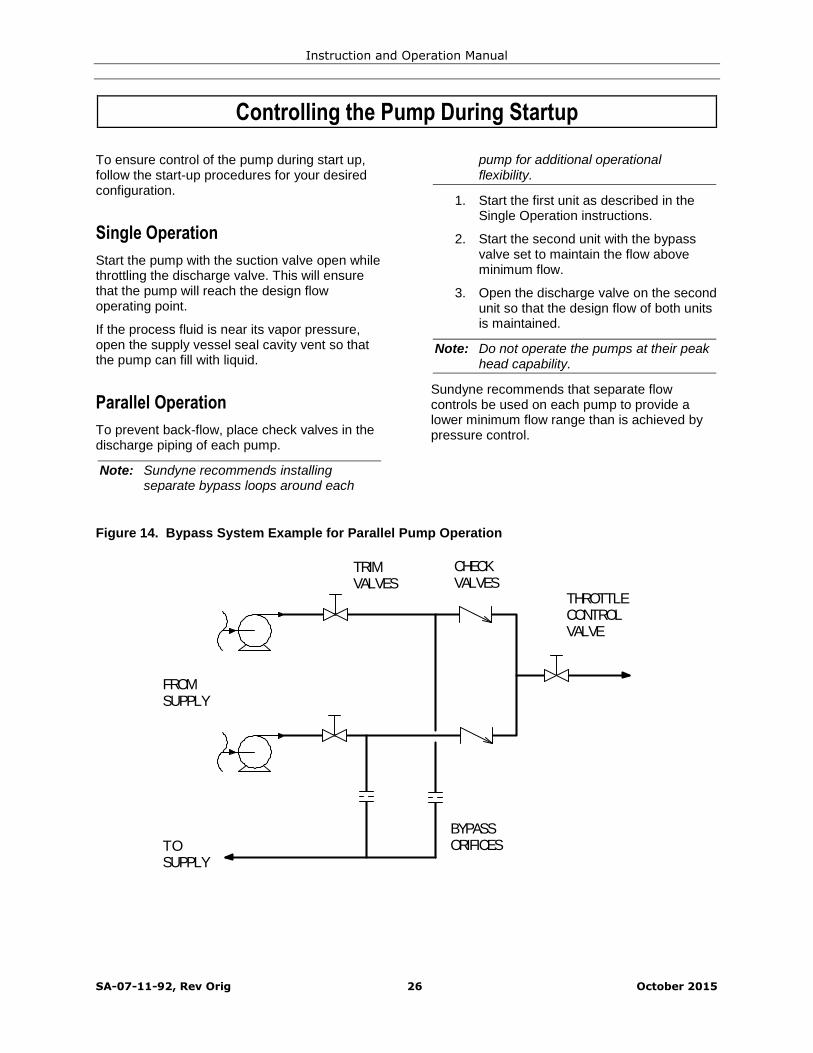
To prevent back-flow, place check valves in thedischarge piping of each pump.
Note: Sundyne recommends installingseparate bypass loops around each
pump for additional operationalflexibility.
1. Start the first unit as described in theSingle Operation instructions.
2. Start the second unit with the bypassvalve set to maintain the flow aboveminimum flow.
3. Open the discharge valve on the secondunit so that the design flow of both unitsis maintained.
Note: Do not operate the pumps at their peakhead capability.
Sundyne recommends that separate flowcontrols be used on each pump to provide alower minimum flow range than is achieved bypressure control.
Figure 14. Bypass System Example for Parallel Pump Operation
BYPASSORIFICES
FROMSUPPLY
TOSUPPLY
THROTTLECONTROLVALVE
TRIMVALVES
CHECKVALVES
Single Operation
Parallel Operation

Instruction and Operation Manual
SA-07-11-92, Rev Orig 27 October 2015
OPERATION & CONTROL
Operation of Sundyne Pumps
Under normal operation, several factors must betaken into consideration to ensure successfulpump operation. Experienced pump operatorswill be aware of jeopardizing factors and theireffects.
Improper flow of liquid into the impeller is themost common operational abuse of centrifugalpumps. Two conditions must exist to preventturbulence at the eye of the impeller.
Proper suction piping, see suction pipingsection.
Liquid reaching the impeller eye musthave enough vapor pressure to preventthe fluid from flashing to a gas in theimpeller. If this condition occurs, it willcause cavitation, which can damage theimpeller and inducer. When centrifugalpumps cavitate the noise sounds like thepump is “pumping gravel”. In high speed,single stage pumps, this sound may notbe discernable. Cavitation can beprevented by maintaining suction pressureat a high enough level and suctiontemperatures low enough to maintain Net
Positive Suction Head (NPSHa) availablegreater than Net Positive Suction Head
(NPSHr) required by the pumps.
Vibration and noise will occur during operation ofcentrifugal pumps if either of two conditionsexist:
Internal flow separations
Recirculation at low flow conditions
If the operator is noticing excessive noise orvibration, operation must be suspended until thecause is determined and corrected. Continueduse may cause damage to the pump.Resonance in the discharge line can accentuate
noise, vibration, and damage to the pump,primarily when a control valve is located anexcessive distance downstream from the pump.
The head and capacity of centrifugal pumps willbe reduced by gas that is drawn in with theliquid. Under normal operating conditions,centrifugal pumps can tolerate up to 2% of gas(by volume). Entrained gases can causedamage to mechanical seals with the exceptionof double seals. If you have entrained gas,contact Sundyne for further instruction.
The point of intersection between the systemcurve and the pump characteristic curvedetermines the flow or operation for thecentrifugal pump. For steady flow to occur, thesystem curve must intersect the pumpcharacteristic curve at a significant angle. Thefollowing diagram gives examples of satisfactoryand unsatisfactory angles of intersection.
Figure 15. Typical Operation
Suction Conditions
Minimum Flow Conditions
Entrained Gases
System Head Curve
A
B

Instruction and Operation Manual
SA-07-11-92, Rev Orig 28 October 2015
Note: In Figure 15, the curve for pump A hasa significant angle of intersection withsystem curves D and E. The systemcurve D could represent a system withthe control valve wide open while curveE could represent the same system butwith the throttle valve closed to reduceflow from flow 1 to flow 2. Pump curveB, on the other hand, will provide onlyflow 2, even with the control valve wideopen (curve D). When the control valveis partially closed to create systemcurve E, the curve E and lower pumpcurve B are practically parallel. The lackof a significant angle of intersectionmeans that the system is unstable,pump flow is likely to fluctuateerratically and not respond to controlvalve position.
Maximizing control is critical when operatingcentrifugal pumps in parallel. One pump canoverpower the other in regards to head at alower total flow. If a simple, unrestricted manifold(Figure 16) connects two pumps at thedischarge head, the discharge head of onepump is imposed on the other.
Figure 17. Parallel Operation
In Figure 17, two pumps operating in parallel willnever have exactly the same performancecurves. At the design point (Q1), with the valveopen, both pumps are operating at the sameflow and head. However, as the system curvechanges with the valve positioning (Q2), pump Acan produce a higher head than pump B. In thiscase pump B will stop flowing altogether,causing it to operate in an unstable minimumflow condition.
Since pump B would effectively be deadheaded,the fluid in it would heat up and boil. Duringinternal boiling, it could encounter liquid sluggingand probable damage to the pump. Properselection of a control system can prevent thissituation.
Figure 16. Parallel Units Common ValveParallel Operation
Instruction and Operation Manual
SA-07-11-92, Rev Orig 29 October 2015
Servicing
Maintenance ScheduleThe timing for maintenance of theSundyne/HMD Sealless pump is establishedprimarily by the liquid end bearing bush system.The time span is longer than for a “cannedmotor” pump because it has over four times thebearing bush wear allowance. It will outlastmechanical seals because it is more tolerant ofsolids and because the pressure x surfacevelocity (PV) values of the bearing bush systemare much lower than the PV values of seal facesin the mechanical seal. Despite theseconservative design advantages, the bearingbush system can develop some wear over aperiod of time, depending on the application.It is possible to avoid the effects of excessivebearing bush wear by the use of plannedmaintenance based on experience on theparticular application involved. This will avoidbreakdown situations arising due to unmonitored
wear causing pump failure by contact betweenother rotating and stationary parts of the pumpliquid end. It is suggested that after initialcommissioning, the pump should be inspectedafter six months to establish the futuremaintenance periods by comparison of therunning clearances with the “as new”dimensions.
Vibration LevelsAn indication as to the condition of pump can beascertained by recording the vibration level ofthe pump and comparing them to level thatwould be expected when the unit is new. Thefollowing table indicates typical levels ofvibration that can be expected during operationat the conditions indicated on the pumpnameplate:-
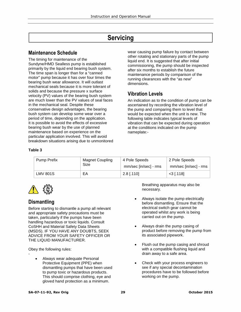
Table 3
Pump Prefix Magnet CouplingSize
4 Pole Speeds
mm/sec [in/sec] - rms
2 Pole Speeds
mm/sec [in/sec] - rms
LMV 801S EA 2.8 [.110] <3 [.118]
DismantlingBefore starting to dismantle a pump all relevantand appropriate safety precautions must betaken, particularly if the pumps have beenhandling hazardous or toxic liquids. ConsultCoSHH and Material Safety Data Sheets(MSDS). IF YOU HAVE ANY DOUBTS, SEEKADVICE FROM YOUR SAFETY OFFICER ORTHE LIQUID MANUFACTURER.
Obey the following rules:-
Always wear adequate PersonalProtective Equipment (PPE) whendismantling pumps that have been usedto pump toxic or hazardous products.This should comprise clothing, eye andgloved hand protection as a minimum.
Breathing apparatus may also benecessary.
Always isolate the pump electricallybefore dismantling. Ensure that theelectrical switch gear cannot beoperated whilst any work is beingcarried out on the pump.
Always drain the pump casing ofproduct before removing the pump fromits associated pipework.
Flush out the pump casing and shroudwith a compatible flushing liquid anddrain away to a safe area.
Check with your process engineers tosee if any special decontaminationprocedures have to be followed beforeworking on the pump.

Instruction and Operation Manual
SA-07-11-92, Rev Orig 30 October 2015
All pumps returned to HMD for factoryservicing must be decontaminated andlabelled in accordance with theSundyne/HMD Return MaterialAuthorization (RMA) procedure.
These safety precautions are to be taken inaddition to any formal safety proceduresspecified by your Company and do notsupersede, change or absolve you form yourstatutory duties under current Governmentlegislation. Our recommendations are based onour current experience. If in doubt or you needto know our latest recommendations – you mustcontact Sundyne/HMD Sealless Pumps.
Fault Finding
FlowchartsThis section is intended to highlight possiblepump problems caused by system designinadequacies or incorrect operation.
Because the sealless pump impeller is notcoupled directly to the electric motor, it isinherently quiet so that any increase in noise is agood indication that there is a problem.
Should it be necessary to dismantle a pump,please read through the dismantling instructionscarefully (see section Dismantling).
No special tools1 are required to dismantle aSundyne/HMD Sealless Pump and no specialskills are required as the pump is simple indesign and robust in construction.
Refurbishing is by replacement and no attemptshould be made to repair pump components bywelding and re-machining.
Clearances between the rotating components inthe pump are comparatively large, so care mustbe taken not to scrap components beforechecking that the clearances are excessive.
In the event that the magnetic coupling is pulledout of step, then the motor must be stoppedIMMEDIATELY because continuation of runningwill damage the magnets.
For further information on fault symptoms,causes and remedies consult the Fault Treeflowcharts in the following pages. (Section FaultFinding).

Instruction and Operation Manual
SA-07-11-92, Rev Orig 31 October 2015
Flow Chart 1
PUMP FAILURE
MAGNET COUPLINGPULLED OUT OF STEP
ROTATE BYHAND
HEAVY(LOCK)
LIGHT
CHECK THEDIRECTION OF
ROTATION
ROTATIONCORRECT
ROTATIONIN-CORRECT
CHANGE TWO OF THETHREE PHASESPRIME
PRIMINGIMPOSSIBLE
PRIMINGNORMAL
LEAKAGE OF FOOT AVALVE
LEAKAGE FROMSUCTION PIPING
CHECK SHUT OFFPRESSURE WITH
DISCHARGE VALVECLOSED
SHUT OFFPRESSURE
NORMAL
SHUT OFF PRESSUREDEFICIENT
GRADUALLY OPENDISCHARGE VALVE
IMPELLER OR NECKRING DAMAGED
RINGS WORN OR AIRTRAPPED
SUCTIONHEAD TOO
LOW
FOREIGNMATTER
BUILD UP INSUCTIONPIPE OF
FOOT VALVE
LIQUID LEVELIN SUCTION
VESSEL TOOLOW
HIGHFRICTIONLOSS IN
SUCTIONPIPING
FOREIGNMATTER
BUILD UP INCASING ORIMPELLER
VAPOURPRESSUREOF PUMPEDLIQUID HIGH
AIR BEINGSUCKED
FROMSUCTION
LINE
CAVITATIONIN SUCTION
PIPE
LOWER THANEXPECTED
HIGHER THANEXPECTED
SYSTEMHEAD TOO
HIGH
DEFECTIVEDISCHARGEOR CHECKVALVE NOTOPENING
FOREIGNMATTER
BLOCKINGDISCHARGE
PIPE
CAVITATIONIN
DISCHARGEPIPE
CONTACTBETWEEN
OUTERMAGNET
RING ANDSHROUD
CONTACTBETWEEN
INNERMAGNET
RING ANDSHROUND
PUMPBEARINGS
LOCKED DUETO BUILD UPOR FOREIGN
MATTER
FOREIGNMATTER
BUILD UP INCASING ORIMPELLER
PRESSUREEQUAL TO SHUT-OFF PRESSURE
SHARP FALL INDISCHARGE PRESSURE
OBSERVE THE SUCTIONGAUGE READING
Instruction and Operation Manual
SA-07-11-92, Rev Orig 32 October 2015
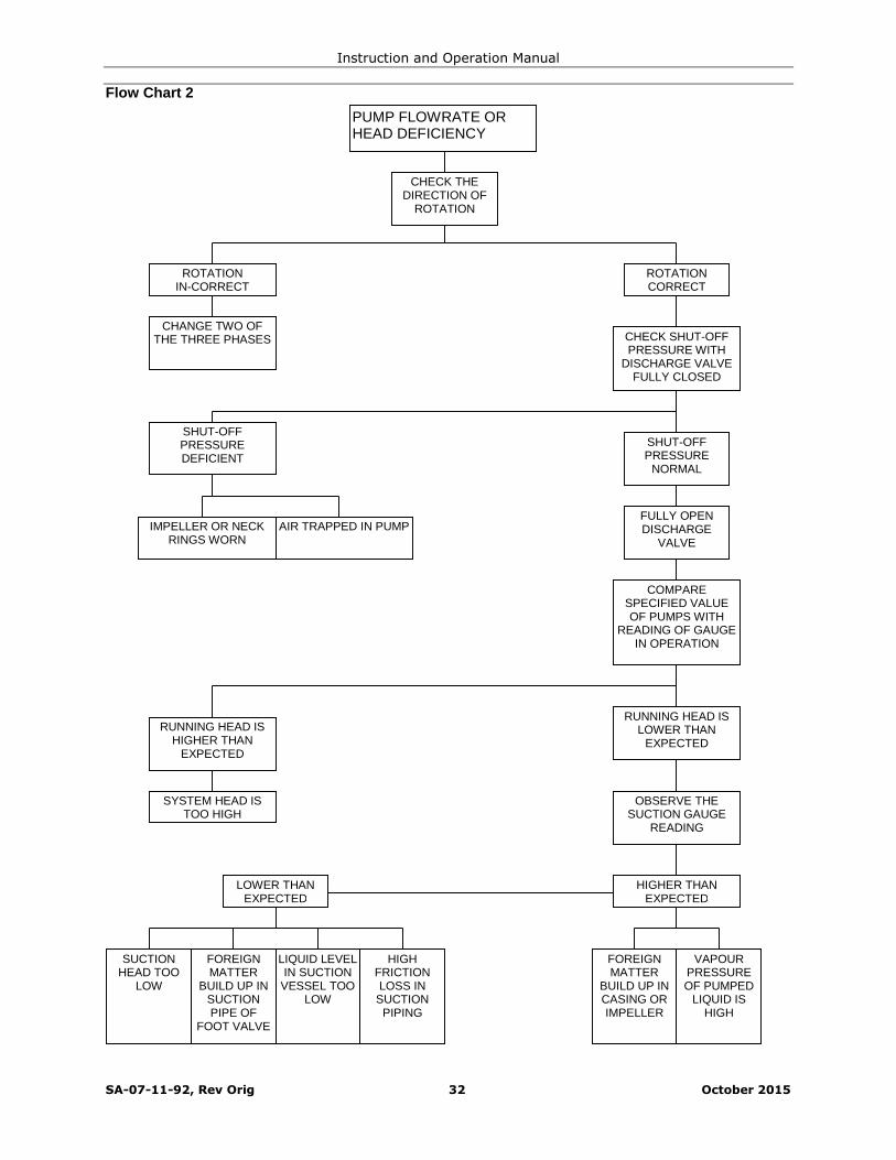
Flow Chart 2
PUMP FLOWRATE ORHEAD DEFICIENCY
CHECK SHUT-OFFPRESSURE WITH
DISCHARGE VALVEFULLY CLOSED
CHECK THEDIRECTION OF
ROTATION
ROTATIONCORRECT
ROTATIONIN-CORRECT
CHANGE TWO OFTHE THREE PHASES
SHUT-OFFPRESSUREDEFICIENT
SHUT-OFFPRESSURE
NORMAL
FULLY OPENDISCHARGE
VALVE
COMPARESPECIFIED VALUEOF PUMPS WITH
READING OF GAUGEIN OPERATION
RUNNING HEAD ISLOWER THAN
EXPECTED
OBSERVE THESUCTION GAUGE
READING
IMPELLER OR NECKRINGS WORN
AIR TRAPPED IN PUMP
RUNNING HEAD ISHIGHER THAN
EXPECTED
SYSTEM HEAD ISTOO HIGH
SUCTIONHEAD TOO
LOW
FOREIGNMATTER
BUILD UP INSUCTIONPIPE OF
FOOT VALVE
LIQUID LEVELIN SUCTION
VESSEL TOOLOW
HIGHFRICTIONLOSS IN
SUCTIONPIPING
FOREIGNMATTER
BUILD UP INCASING ORIMPELLER
VAPOURPRESSUREOF PUMPED
LIQUID ISHIGH
LOWER THANEXPECTED
HIGHER THANEXPECTED

Instruction and Operation Manual
SA-07-11-92, Rev Orig 33 October 2015
Flow Chart 3MOTOR CURRENT HIGH
MEASURE CURRENTWITH DISCHARGE
VALVE FULLYCLOSED
CHECK THEDIRECTION OF
ROTATION
ROTATIONCORRECT
ROTATIONIN-CORRECT
CHANGE TWO OFTHE THREE PHASES
ABNORMAL
OVER RATE OFFLOW
HEAVY RESISTANCEIS FELT WHEN
ROTATED MANUALLY
SPECIFIC GRAVITY ORVISCOSITY OF
PUMPED LIQUID ISHIGH
PUMP BEARINGSDAMAGED
DIS-ASSEMBLE
ANDREPLACE
DEFECTIVEPARTS
MOTORROTOR
DAMAGEDREQUIRING
NEW MOTOR
DIS-ASSEMBLE
AND REMOVEFOREIGNMATTER
ADJUSTRATE OF
FLOW
FOREIGN MATTERBUILD UP IN PUMP
NORMAL

Instruction and Operation Manual
SA-07-11-92, Rev Orig 34 October 2015
Flow Chart 4 EXCESSIVE NOISE ANDVIBRATION
LOCATE SOURCE OFNOISE ANDVIBRATION
CHECK THEDIRECTION OF
ROTATION
ROTATIONCORRECT
ROTATIONIN-CORRECT
CHANGE TWO OFTHE THREE PHASES
INSIDE THEPUMP
FROMFOUNDATION OR
PIPING
CHECK THESUCTION GAUGE
READING
BEARINGSDAMAGED
BEARINGSWORN
FOREIGNMATTERBUILD UPIN PUMP
RESONANCEOF PUMP
FOUNDATION
HIGHERTHAN
EXPECTED
LOWERTHAN
EXPECTED
CAVITATION WATERHAMMER
OUTERMAGNET
RING NOTSECURED TODRIVE SHAFTCORRECTLY
BEARINGSWORN ORCOUPLING
MIS-ALIGNED

Instruction and Operation Manual
SA-07-11-92, Rev Orig 35 October 2015
Pump Diagnostics
Several system factors may affect theperformance of the pump. These factors are:
Temperature
Specific gravity
Suction pressure
Driver Speed
Flow rate
Control characteristics
These factors as well as internal problems mustbe considered when analyzing pump systemperformance. The following table givesdiagnostic information that can be useful whenanalyzing gearbox and pump performanceproblems
Table 4. Pump Diagnostics
Situation/Symptom Possible Cause Investigative/Corrective Action
No flow, no pressure atstart-up.
Pump not completely filled with liquid. Bleed all vapor or air from vent.
Allow more cool-down time if pumping lowtemperature fluid.
Check suction line for air leak if suctionpressure is lower than atmospheric.
NPSH actually lower than NPSH requirement listed onspecification sheet.
Suction line blocked – check suction screenand valve.
Excessive pressure drop through suctionpiping.
Flow restricted by vapor pockets in high pointsof suction line.
Suction tank level or pressure too low.
Entrained air or vapor in pumped fluid.
NPSH reduced by presence of more volatilefluid in process fluid.
Failure of drive component, such as interconnectingshaft or impeller key, or item missing from assembly.
Disassemble and inspect.
Reverse direction of rotation. Direction of driver shaft rotation must be asshown by arrow on pump casing. Note: Impellerand driver rotate in the same direction.
Insufficient total head. Flow too high. Check total head and flow rate againstperformance curve.
Wrong direction of driver shaft rotation. (It is possiblefor the pump to develop greater than 50 percentdesign total head in this condition).
Direction of driver shaft rotation must be asshown by arrow on pump casing. Note: Impellerand driver rotate in the same direction.
NPSH actually lower than NPSH requirement listed onspecification sheet.
Refer to solutions listed under “No flow, nopressure at start-up”.
Flow too low, causing overheating of fluid resulting ininternal boiling and unstable pump operation.
Increase through-flow rate.
Bypass part of pump discharge to supply tank.
Diffuser discharge throat partially plugged orimpeller damaged by passage of a solid particle.
Clean these areas of all obstructions and restoresurfaces to a smooth polished finish free of allcorrosion pitting. Edge of diffuser throat must besharp.
Instruction and Operation Manual
SA-07-11-92, Rev Orig 36 October 2015
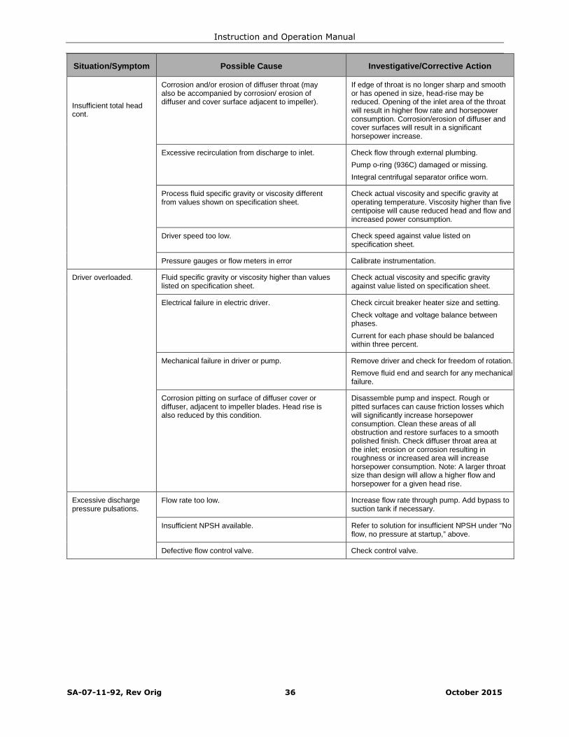
Situation/Symptom Possible Cause Investigative/Corrective Action
Insufficient total headcont.
Corrosion and/or erosion of diffuser throat (mayalso be accompanied by corrosion/ erosion ofdiffuser and cover surface adjacent to impeller).
If edge of throat is no longer sharp and smoothor has opened in size, head-rise may bereduced. Opening of the inlet area of the throatwill result in higher flow rate and horsepowerconsumption. Corrosion/erosion of diffuser andcover surfaces will result in a significanthorsepower increase.
Excessive recirculation from discharge to inlet. Check flow through external plumbing.
Pump o-ring (936C) damaged or missing.
Integral centrifugal separator orifice worn.
Process fluid specific gravity or viscosity differentfrom values shown on specification sheet.
Check actual viscosity and specific gravity atoperating temperature. Viscosity higher than fivecentipoise will cause reduced head and flow andincreased power consumption.
Driver speed too low. Check speed against value listed onspecification sheet.
Pressure gauges or flow meters in error Calibrate instrumentation.
Driver overloaded. Fluid specific gravity or viscosity higher than valueslisted on specification sheet.
Check actual viscosity and specific gravityagainst value listed on specification sheet.
Electrical failure in electric driver. Check circuit breaker heater size and setting.
Check voltage and voltage balance betweenphases.
Current for each phase should be balancedwithin three percent.
Mechanical failure in driver or pump. Remove driver and check for freedom of rotation.
Remove fluid end and search for any mechanicalfailure.
Corrosion pitting on surface of diffuser cover ordiffuser, adjacent to impeller blades. Head rise isalso reduced by this condition.
Disassemble pump and inspect. Rough orpitted surfaces can cause friction losses whichwill significantly increase horsepowerconsumption. Clean these areas of allobstruction and restore surfaces to a smoothpolished finish. Check diffuser throat area atthe inlet; erosion or corrosion resulting inroughness or increased area will increasehorsepower consumption. Note: A larger throatsize than design will allow a higher flow andhorsepower for a given head rise.
Excessive dischargepressure pulsations.
Flow rate too low. Increase flow rate through pump. Add bypass tosuction tank if necessary.
Insufficient NPSH available. Refer to solution for insufficient NPSH under “Noflow, no pressure at startup,” above.
Defective flow control valve. Check control valve.
Instruction and Operation Manual
SA-07-11-92, Rev Orig 37 October 2015
Maintenance
Before disassembling a pump all relevant and appropriate safety precautions must be taken.SEEK ADVICE FROM YOUR SAFETY REPRESENTATIVE OR THE MANUFACTURER IF YOUHAVE ANY DOUBTS.
Care should be taken in assembling magnetic components due to their attraction with ferrousmaterials. Also particular care should be exercised when inserting or withdrawing the InnerMagnet Ring into or out of the Containment Shell contained within the Coupling Housing, due tothe axial pull of the Outer Magnet Ring.
General Safety

Instruction and Operation Manual
SA-07-11-92, Rev Orig 38 October 2015
The table of tools shown below is fully comprehensive and allows for complete strip-down and re-build ofpump.
Tool List
Hexagon Bit Socket
and / or
Hexagon Key
3/16”
7/32”
¼”
5/16”
3/8”
½”
8 mm (IEC Motors)
Socket
and / or
Spanner
¾” (Deep)
1-1/8” (Deep)
1-1/4”
50 mm
17 AF (IEC 90 Motor)
19 AF (IEC 100 to 132 Motor)
24 AF (IEC 160 to 225 Motor)
Torque Wrenches For torque settings from 25 Nm (18 lbf-ft) to 300Nm (220 lbf-ft)
General tools required
Ratchet
Extension bar
Soft mallet
Eye Bolts 5/16" x 3
Eye Bolt 1/2" UNC x 3
Eye Bolt 5/8” UNC x 2
Eye Bolt M16 x 2 (IEC Motors)
Lifting Equipment x 2
Pry bar x 2
Dial Test Indicator complete with magnetic base
Loctite 242 Threadlocker (or similar)
Anti-seize compound
Steel Discs Ø3.50 X 1.0 thick [Ø90mm X 25 mm thick] x 2 (forReplacement of Bushes and Thrust Pad)
Tools Required

Instruction and Operation Manual
SA-07-11-92, Rev Orig 39 October 2015
Lifting Lugs are intended to lift the entire pump assembly. Never use the lifting lugs to stand apump up from a horizontal position. The lugs are intended for a vertical lifting direction only. Eyebolts attached to the motor are intended for lifting the motor only.
Quantity Weight Capacity2 Up to 1650 lbs (750 kg)4 Over 1650 lbs (750 kg)
Sundyne recommends the use of swivel hoist rings for the handling of parts and assemblies asdemonstrated in the following section. Use of other lifting devices may result in harm to the useror damage to equipment.
Quantity Size3 5/16-183 ½-13 UNC2 5/8-11 UNC
Lifting Points
LiftingLugs
Swivel Hoist Ring
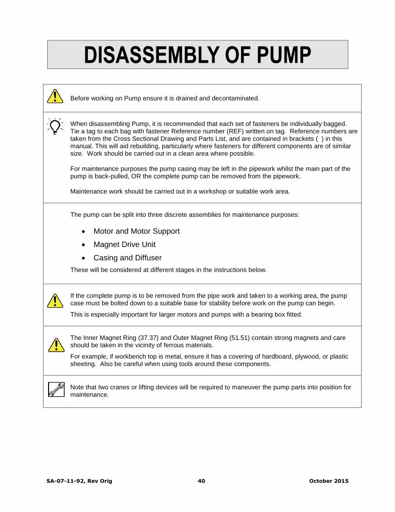
SA-07-11-92, Rev Orig 40 October 2015
DISASSEMBLY OF PUMP
Before working on Pump ensure it is drained and decontaminated.
When disassembling Pump, it is recommended that each set of fasteners be individually bagged.Tie a tag to each bag with fastener Reference number (REF) written on tag. Reference numbers aretaken from the Cross Sectional Drawing and Parts List, and are contained in brackets ( ) in thismanual. This will aid rebuilding, particularly where fasteners for different components are of similarsize. Work should be carried out in a clean area where possible.
For maintenance purposes the pump casing may be left in the pipework whilst the main part of thepump is back-pulled, OR the complete pump can be removed from the pipework.
Maintenance work should be carried out in a workshop or suitable work area.
The pump can be split into three discrete assemblies for maintenance purposes:
Motor and Motor Support
Magnet Drive Unit
Casing and Diffuser
These will be considered at different stages in the instructions below.
If the complete pump is to be removed from the pipe work and taken to a working area, the pumpcase must be bolted down to a suitable base for stability before work on the pump can begin.
This is especially important for larger motors and pumps with a bearing box fitted.
The Inner Magnet Ring (37.37) and Outer Magnet Ring (51.51) contain strong magnets and careshould be taken in the vicinity of ferrous materials.
For example, if workbench top is metal, ensure it has a covering of hardboard, plywood, or plasticsheeting. Also be careful when using tools around these components.
Note that two cranes or lifting devices will be required to maneuver the pump parts into position formaintenance.
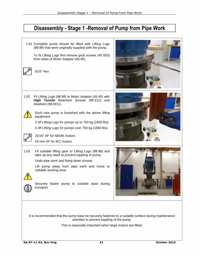
Disassembly Stage 1 – Removal of Pump from Pipe Work
SA-07-11-92, Rev Orig 41 October 2015
Disassembly - Stage 1 -Removal of Pump from Pipe Work
1.01 Complete pump should be lifted with Lifting Lugs(98.98) that were originally supplied with the pump.
To fit Lifting Lugs first remove grub screws (45.S53)from webs of Motor Adaptor (45.45).
5/16” Hex
1.02 Fit Lifting Lugs (98.98) to Motor Adaptor (45.45) withHigh Tensile Retention Screws (98.S11) andWashers (98.W11).
Each new pump is furnished with the above liftingequipment.
2 off Lifting Lugs for pumps up to 750 kg (1650 lbs).
4 off Lifting Lugs for pumps over 750 kg (1650 lbs).
15/16” AF for NEMA motors
24 mm AF for IEC motors
1.03 Fit suitable lifting gear to Lifting Lugs (98.98) andtake up any slack to prevent toppling of pump.
Undo pipe work and fixing down screws.
Lift pump away from pipe work and move tosuitable working area.
Securely fasten pump to suitable base duringtransport.
It is recommended that the pump base be securely fastened to a suitable surface during maintenanceactivities to prevent toppling of the pump.
This is especially important when large motors are fitted.

Disassembly Stage 1 – Removal of Pump from Pipe Work
SA-07-11-92, Rev Orig 42 October 2015
1.04 Remove Retention Screws (98.S11), Washers(98.W11) and Lifting Lugs (98.98) from MotorAdaptor (45.45).
15/16” AF for NEMA motors
24 mm AF for IEC motors
1.05 Image shows a complete pump ready fordisassembly.
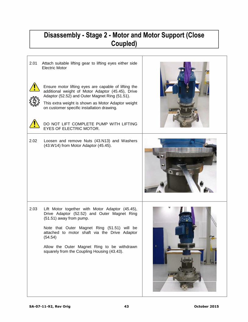
SA-07-11-92, Rev Orig 43 October 2015
Disassembly - Stage 2 - Motor and Motor Support (CloseCoupled)
2.01 Attach suitable lifting gear to lifting eyes either sideElectric Motor
Ensure motor lifting eyes are capable of lifting theadditional weight of Motor Adaptor (45.45), DriveAdaptor (52.52) and Outer Magnet Ring (51.51).
This extra weight is shown as Motor Adaptor weighton customer specific installation drawing.
DO NOT LIFT COMPLETE PUMP WITH LIFTINGEYES OF ELECTRIC MOTOR.
2.02 Loosen and remove Nuts (43.N13) and Washers(43.W14) from Motor Adaptor (45.45).
2.03 Lift Motor together with Motor Adaptor (45.45),Drive Adaptor (52.52) and Outer Magnet Ring(51.51) away from pump.
Note that Outer Magnet Ring (51.51) will beattached to motor shaft via the Drive Adaptor(54.54)
Allow the Outer Magnet Ring to be withdrawnsquarely from the Coupling Housing (43.43).

Disassembly – Stage 2 – Motor and Motor Support
SA-07-11-92, Rev Orig 44 October 2015
2.04 Fit 2 off Eye Bolts to tapped holes in webs of MotorAdaptor (45.45).
These Eye Bolts should be positioned in betweenthe Lifting Eyes of electric motor and on the sameside as the motor terminal box.
5/16” Eye Bolts for NEMA Motors
M16 Eye Bolts for IEC Motors
2.05 Use a second lifting device and attach lifting gear toeye bolts on Motor Adaptor (45.45).
Lift motor assembly into a horizontal position.
Lower assembly onto a wooden pallet or similar sothat motor is resting on pallet whilst Motor Adaptoroverhangs the edge by a minimal amount.
2.06 There is no need to dismantle the assemblyfurther unless inspection or replacement ofparts is required.
Move to Stage 3 if assembly is in good order.
A run-out check of the Outer Magnet Ring (51.51)should be performed to ensure it is within limits.
Set magnetic base on mounting face of MotorAdaptor (45.45) and check run-out of bump ring withDial Test Indicator.
Maximum allowable run-out is 0.25 mm (0.010”)
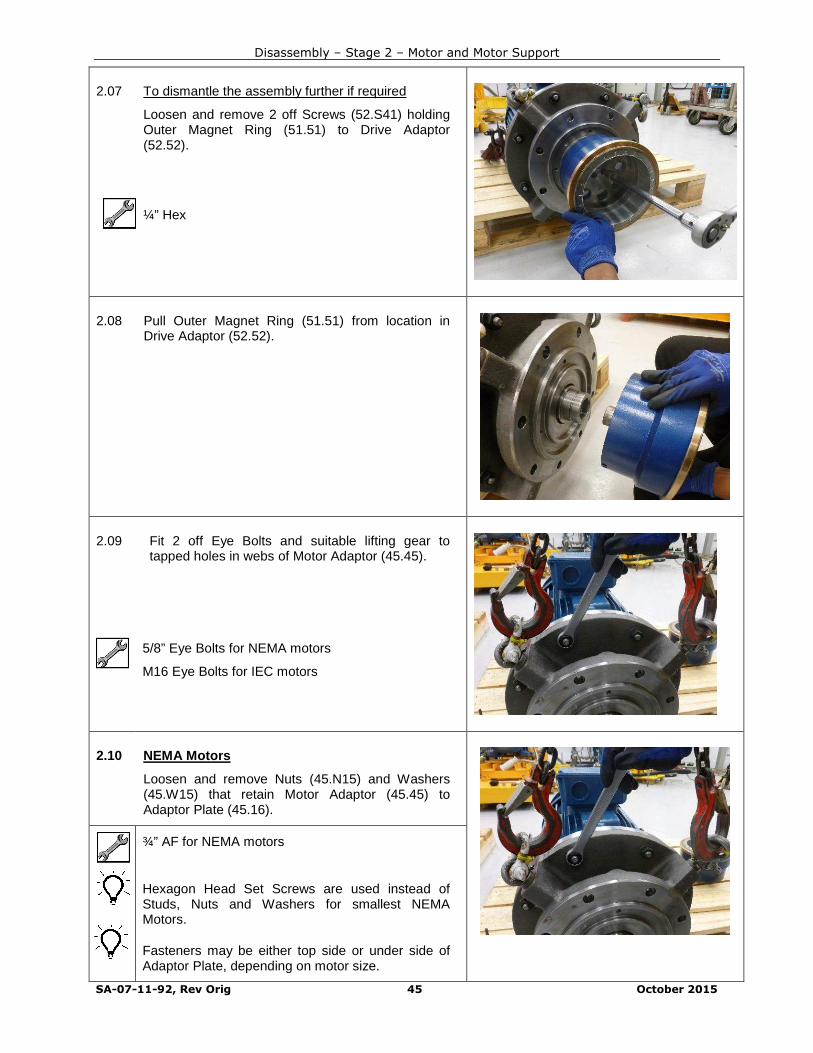
Disassembly – Stage 2 – Motor and Motor Support
SA-07-11-92, Rev Orig 45 October 2015
2.07 To dismantle the assembly further if required
Loosen and remove 2 off Screws (52.S41) holdingOuter Magnet Ring (51.51) to Drive Adaptor(52.52).
¼” Hex
2.08 Pull Outer Magnet Ring (51.51) from location inDrive Adaptor (52.52).
2.09 Fit 2 off Eye Bolts and suitable lifting gear totapped holes in webs of Motor Adaptor (45.45).
5/8” Eye Bolts for NEMA motors
M16 Eye Bolts for IEC motors
2.10 NEMA Motors
Loosen and remove Nuts (45.N15) and Washers(45.W15) that retain Motor Adaptor (45.45) toAdaptor Plate (45.16).
¾” AF for NEMA motors
Hexagon Head Set Screws are used instead ofStuds, Nuts and Washers for smallest NEMAMotors.
Fasteners may be either top side or under side ofAdaptor Plate, depending on motor size.
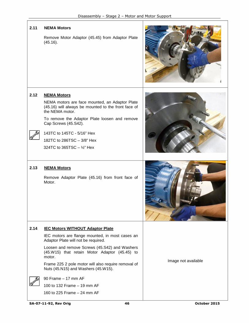
Disassembly – Stage 2 – Motor and Motor Support
SA-07-11-92, Rev Orig 46 October 2015
2.11 NEMA Motors
Remove Motor Adaptor (45.45) from Adaptor Plate(45.16).
2.12 NEMA Motors
NEMA motors are face mounted, an Adaptor Plate(45.16) will always be mounted to the front face ofthe NEMA motor.
To remove the Adaptor Plate loosen and removeCap Screws (45.S42).
143TC to 145TC - 5/16” Hex
182TC to 286TSC – 3/8” Hex
324TC to 365TSC – ½” Hex
2.13 NEMA Motors
Remove Adaptor Plate (45.16) from front face ofMotor.
2.14 IEC Motors WITHOUT Adaptor Plate
IEC motors are flange mounted, in most cases anAdaptor Plate will not be required.
Loosen and remove Screws (45.S42) and Washers(45.W15) that retain Motor Adaptor (45.45) tomotor.
Frame 225 2 pole motor will also require removal ofNuts (45.N15) and Washers (45.W15).
Image not available
90 Frame – 17 mm AF
100 to 132 Frame – 19 mm AF
160 to 225 Frame – 24 mm AF
Disassembly – Stage 2 – Motor and Motor Support
SA-07-11-92, Rev Orig 47 October 2015
2.15 IEC Motors WITHOUT Adaptor Plate
Remove Motor Adaptor (45.45) from Motor.
Image not available
2.16 IEC Motors WITH Adaptor Plate
A separate Adaptor Plate (45.16) is only requiredfor the largest motors.
Loosen and remove Nuts (45.N15) and Washers(45.W15) that retain Motor Adaptor (45.45) toAdaptor Plate (45.16). Image not available
15/16” AF
2.17 IEC Motors WITH Adaptor Plate
Remove Motor Adaptor (45.45) from Adaptor Plate(45.16).
Image not available
2.18 IEC Motors WITH Adaptor Plate
Loosen and remove Screws (45.S42) and Washers(45.W15) that retain Adaptor Plate (45.16) to Motor.
Image not available

Disassembly – Stage 2 – Motor and Motor Support
SA-07-11-92, Rev Orig 48 October 2015
2.19 IEC Motors WITH Adaptor Plate
Remove Adaptor Plate (45.16) from Motor.
Image not available

Disassembly – Stage 2 – Motor and Motor Support
SA-07-11-92, Rev Orig 49 October 2015
2.20 Remove Draw Screws (52.S42) from DriveAdaptor (52.52).
IEC Motors – 8 mm Hex
NEMA 143TC to 215TC – 7/32” Hex
NEMA 254TC to 365TSC – 5/16” Hex
A large screw driver or similar tool can be usedbehind the flange between one of the screws andthe Drive Adaptor body to prevent the Drive Adaptorfrom turning.
2.21 Fit removed Draw Screws (52.S42) into tappedholes in front face of Drive Adaptor (52.52) andtighten down onto taper ring to push ring free fromtaper.
Image not available
2.22 Once taper ring has been loosened the DriveAdaptor (52.52) can be pulled free from the motorshaft.
2.23 Finally, remove taper ring from motor shaft.
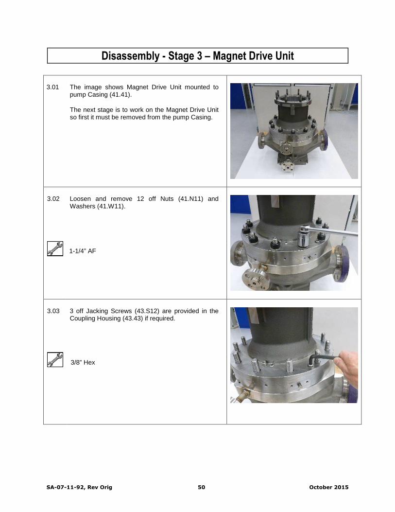
SA-07-11-92, Rev Orig 50 October 2015
Disassembly - Stage 3 – Magnet Drive Unit
3.01 The image shows Magnet Drive Unit mounted topump Casing (41.41).
The next stage is to work on the Magnet Drive Unitso first it must be removed from the pump Casing.
3.02 Loosen and remove 12 off Nuts (41.N11) andWashers (41.W11).
1-1/4” AF
3.03 3 off Jacking Screws (43.S12) are provided in theCoupling Housing (43.43) if required.
3/8” Hex

Disassembly – Stage 3 – Magnet Drive Unit
SA-07-11-92, Rev Orig 51 October 2015
3.04 Fit 2 off Eye Bolts to tapped holes in outside of topflange of Coupling Housing (43.43)
Attach suitable lifting gear to Eye Bolts andwithdraw Magnet Drive Unit from pump Casing(41.41).
(Image shows optional inducer fitted to impeller)
½” Eye Bolt
3.05 Fit 1 off Eye Bolt to tapped hole in outside of bottomflange of Coupling Housing (43.43.
Use a second lifting device to raise the MagnetDrive Unit into a horizontal position.
(Image shows optional inducer fitted to impeller)
½” Eye Bolt
3.06 Remove 2 off Jacking Screws (16.S51) fromAdaptor Ring (16.16) and replace with 2 off EyeBolts.
Lift front of Magnet Drive Unit into the verticalposition and set down on a suitable workingsurface.
2 x Eye Bolts 5/8”
CAUTION – Assembly is stable but top heavy

Disassembly – Stage 3 – Magnet Drive Unit
SA-07-11-92, Rev Orig 52 October 2015
3.07 Remove 12 off Cap Screws (43.S55) from AdaptorRing (16.16).
5/16” Hexagon
3.08 Lift away Adaptor Ring (16.16).
Lifting gear can be used BUT be careful not totopple unit if ring is reluctant to become free.
Alternatively remove Eye Bolts and re-fit JackingScrews (16.S51), Adaptor Ring may be lifted byhand after jacking free.
3.09 Remove O-ring (14.OR2) from front shoulder ofCasing Plate (14.14) and discard.
O-ring may have been left in Diffuser (33.33) whenMagnet Drive was lifted from Casing (41.41).
Find O-ring and discard.
3.10 Remove O-ring (14.OR3) from groove in outsidediameter of Casing Plate (14.14) and discard.

Disassembly – Stage 3 – Magnet Drive Unit
SA-07-11-92, Rev Orig 53 October 2015
3.11 Remove Gasket (20.17) from shoulder ofContainment Shell (20.20) and discard.
Gasket may have been left in Adaptor Ring (16.16).
Find Gasket and discard.
3-12 Remove 3 off Cap Screws (20.S41) from CasingPlate (14.14).
Some sizes of Impeller (06.06) may cover or partlycover Screws. If this is the case, remove Impeller toaccess the Screws and then replace but do not fullytighten (see later for Impeller removal)
7/32" or 1/4" Hex
3.13 If required, fit 2 off Screws removed from CasingPlate (14.14) into recessed tapped holes in face ofCasing Plate in order to jack Casing Plate free fromContainment Shell (20.20).
3.14 Fit 2 off Eye Bolts to tapped holes in outsidediameter of Casing Plate (14.14).
Lift Casing Plate (14.14) complete with rotatingassembly away from Containment Shell (20.20)
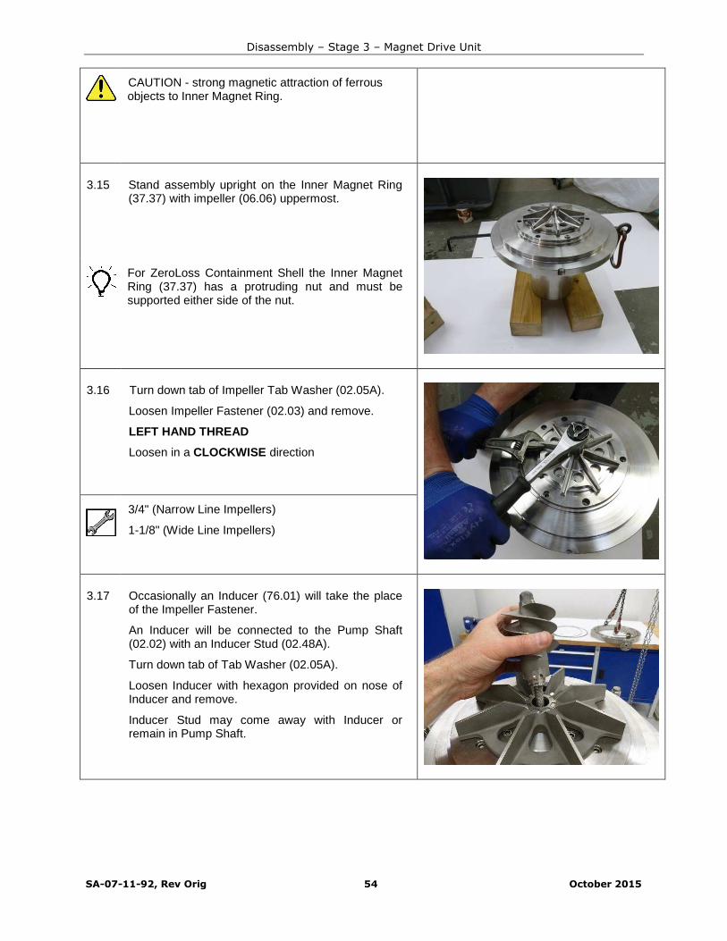
Disassembly – Stage 3 – Magnet Drive Unit
SA-07-11-92, Rev Orig 54 October 2015
CAUTION - strong magnetic attraction of ferrousobjects to Inner Magnet Ring.
3.15 Stand assembly upright on the Inner Magnet Ring(37.37) with impeller (06.06) uppermost.
For ZeroLoss Containment Shell the Inner MagnetRing (37.37) has a protruding nut and must besupported either side of the nut.
3.16 Turn down tab of Impeller Tab Washer (02.05A).
Loosen Impeller Fastener (02.03) and remove.
LEFT HAND THREAD
Loosen in a CLOCKWISE direction
3/4" (Narrow Line Impellers)
1-1/8" (Wide Line Impellers)
3.17 Occasionally an Inducer (76.01) will take the placeof the Impeller Fastener.
An Inducer will be connected to the Pump Shaft(02.02) with an Inducer Stud (02.48A).
Turn down tab of Tab Washer (02.05A).
Loosen Inducer with hexagon provided on nose ofInducer and remove.
Inducer Stud may come away with Inducer orremain in Pump Shaft.

Disassembly – Stage 3 – Magnet Drive Unit
SA-07-11-92, Rev Orig 55 October 2015
3.18 Remove Tab Washer (02.05A) and Impeller (06.06)from Pump Shaft (02.02).
3.19 Remove 3 off Screws (14.S45) from Casing PlateCover (14.40).
7/32" or 1/4" Hex
3.20 Fit 2 off Screws (14.S45) to recessed tapped holesprovided and lift away Casing Plate Cover (14.40).
Screws (14.S45) can also be used to jack CasingPlate Cover if required.
3.21 Fit 2 off Screws (14.S45) from Casing Plate Coverto tapped holes provided in back of Thrust WasherHolder (07.07).
Lift Thrust Washer Holder away from Pump Shaft(02.02)

Disassembly – Stage 3 – Magnet Drive Unit
SA-07-11-92, Rev Orig 56 October 2015
Note that Front Thrust Washer (07.07A) is locatedin back of Thrust Washer Holder (07.07) and maydrop out of its location when the Thrust WasherHolder is removed.
Care must be taken to avoid damage to ThrustWasher which is made of Silicon Carbide.
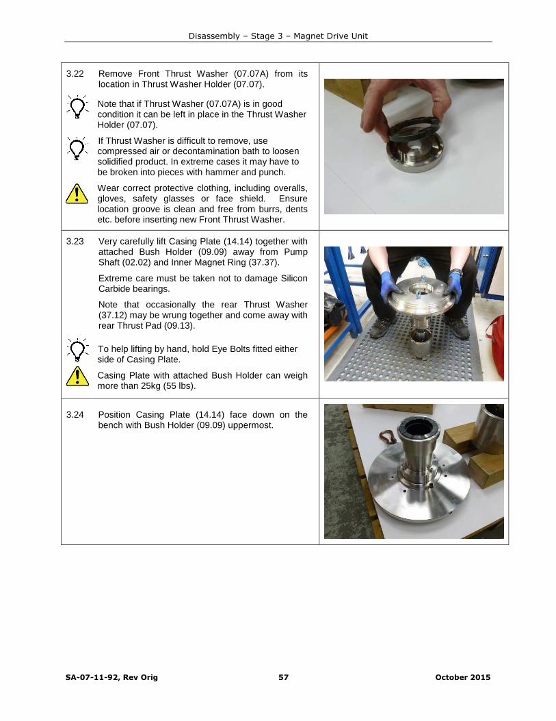
Disassembly – Stage 3 – Magnet Drive Unit
SA-07-11-92, Rev Orig 57 October 2015
3.22 Remove Front Thrust Washer (07.07A) from itslocation in Thrust Washer Holder (07.07).
Note that if Thrust Washer (07.07A) is in goodcondition it can be left in place in the Thrust WasherHolder (07.07).
If Thrust Washer is difficult to remove, usecompressed air or decontamination bath to loosensolidified product. In extreme cases it may have tobe broken into pieces with hammer and punch.
Wear correct protective clothing, including overalls,gloves, safety glasses or face shield. Ensurelocation groove is clean and free from burrs, dentsetc. before inserting new Front Thrust Washer.
3.23 Very carefully lift Casing Plate (14.14) together withattached Bush Holder (09.09) away from PumpShaft (02.02) and Inner Magnet Ring (37.37).
Extreme care must be taken not to damage SiliconCarbide bearings.
Note that occasionally the rear Thrust Washer(37.12) may be wrung together and come away withrear Thrust Pad (09.13).
To help lifting by hand, hold Eye Bolts fitted eitherside of Casing Plate.
Casing Plate with attached Bush Holder can weighmore than 25kg (55 lbs).
3.24 Position Casing Plate (14.14) face down on thebench with Bush Holder (09.09) uppermost.

Disassembly – Stage 3 – Magnet Drive Unit
SA-07-11-92, Rev Orig 58 October 2015
3.25 Remove 4 off Bush Holder Screws (14.S41).
Fit 2 off Screws to tapped holes for jacking ifrequired.
Only two of the tapped holes will have correctthread for the screws.
3/16" Hex
3.26 Remove Bush Holder (09.09) from Casing Plate(14.14).
Only store Bush Holder on its side, or if storedvertically ensure Silicon Carbide bearing rests onsoft protective matting surface.
For changing Silicon Carbide Bushes andThrust Pad refer to appropriate section shownon Contents page at the beginning of thismanual.
If Bushes and Thrust Pad are not worn or damagedthey can be left in place.
3.27 Wedge rags inside Inner Magnet Ring (37.37) andup to Back Thrust Washer (37.12) to preventThrust Washer from falling out during handling.
The Inner Magnet Ring contains strong magnetsand care should be taken near ferrous materials.
For example, if workbench top is metal ensure ithas a covering of hardboard, plywood, or plasticsheeting. Also be careful when using tools aroundthis component.

Disassembly – Stage 3 – Magnet Drive Unit
SA-07-11-92, Rev Orig 59 October 2015
3.28 Turn over Inner Magnet Ring (37.37) and hold in avice with soft jaws fitted. Turn assembly clockwiseuntil key (02.K31) locks against jaw before fullytightening vice.
Turn down tab on Coupling Washer (02.05) andloosen but do not remove Coupling Nut (02.36).
LEFT HAND THREAD
Loosen in a CLOCKWISE direction
50mm AF
3.29 Stand Inner Magnet Ring (37.37) on its side onprotective surface and remove Coupling Nut (02.36)and Tab Washer (02.05).
Drift out Shaft (02.02) with a soft mallet.
Support Pump Shaft as it comes free from itslocation to protect Silicon Carbide Sleeves (02.86)and Thrust Washer (37.12).
3.30 Remove Back Thrust Washer (37.12) from InnerMagnet Ring (37.37).
Note that if Back Thrust Washer (37.12) is in goodcondition it can be left in place in the Inner MagnetRing (37.37).
If difficult to remove, use compressed air ordecontamination bath to loosen solidified product.In extreme cases it may have to be broken intopieces with hammer and punch.
Wear correct protective clothing, including overalls,gloves, safety glasses or face shield. Ensurelocation groove is clean and free from burrs, dentsetc. before inserting new Front Thrust Washerwhen re-building.

Disassembly – Stage 3 – Magnet Drive Unit
SA-07-11-92, Rev Orig 60 October 2015
3.31 If the Back Thrust Washer (37.12) has beenremoved then also remove and discard AlignmentPad (37.39) from Inner Magnet Ring (37.37).
3.32 Hold main body of Pump Shaft (02.02) in a vicewith soft jaws.
Grip the Silicon Carbide Sleeve (08.86) with bothhands and pull Sleeve from Pump Shaft (02.02).
Image not availableA sharp pulling action may be required to overcomefriction of the locating O-rings (02.OR1) in the boreof the Sleeve.
Wear appropriate gloves and eye protection asSilicon Carbide is brittle and can produce sharpedges when broken.
If Shaft Sleeves (02.86) are not worn or damagedthey can be left in place.
3.33 ALTERNATIVE METHOD
Carefully grip Silicon Carbide Sleeve (02.86) in softjaws of a bench vice.
Use a soft mallet to drift Pump Shaft (02.02) fromSleeve.
Support Shaft as it exits Sleeve.
Soft jaws with fibre faces must be used to avoidcracking Silicon Carbide Sleeves.
Over-tightening the vice will break the Sleeve.
Eye protection must be worn in case SiliconCarbide fractures or splinters.

Disassembly – Stage 3 – Magnet Drive Unit
SA-07-11-92, Rev Orig 61 October 2015
3.34 Remove O-Rings (02.OR1) from their grooves onboth ends of Shaft and discard.
Put all parts disassembled so far in clean, dry, safeplace until rest of Pump has been stripped.
Magnet Drive Unit is now completely disassembled

SA-07-11-92, Rev Orig 62 October 2015
Disassembly - Stage 4 – Casing and Diffusers
Casing with Diffuser fitted, ready for disassembly
Image not available
4.01 Fit 3 off Eye Bolts to tapped holes in top face ofDiffuser (33.33).
Attach suitable lifting gear and lift Diffuser frompump Casing (41.41).
3 x Eye Bolts 3/16”
4.02 ALTERNATIVE METHOD
If a large diameter impeller is fitted there may notbe enough wall thickness for eye bolt holes inDiffuser (33.33).
If this is the case use a 3 leg puller (with reverselegs) through the eye of the Diffuser to enableextraction from the Casing (41.41).

Disassembly – Stage 4 – Casing and Diffusers
SA-07-11-92, Rev Orig 63 October 2015
4.03 Remove O-Ring (33.OR2) from Diffuser (33.33)and discard.
4.04 Remove O-Ring (41.OR1) from bottom face ofCasing (41.41) and discard.
4.05 High head hydraulics are fitted with a ConeExtension in the side wall of pump Casing (41.41)positioned in line with the discharge nozzle.
Removal of Cone Extension is only required forinspection or replacement purposes.
To remove Cone Extension, push in one end andthe other end will slide out. Remove completelyfrom cavity.
A Soft Mallet may be required to aid removal.
4.06 Two pins (41.49B) in the bottom face of Casing(41.41) can be left in place unless they aredamaged in which case they will need to be pulledout.

SA-07-11-92, Rev Orig 64 October 2015
ASSEMBLY OF PUMPTo prevent leaks, ensure all Jacking Screws used to disassemble the Pump are either removed orwithdrawn to their original position during assembly.
Make sure all machined surfaces are clean and free from debris, bumps, bruises and scratches.
Note that small errors of alignment near the motor are magnified further away from the motor wherethe Outer Magnet Ring (51.51) will be running with close clearances to other components.
Dress any surface damage with a stone.
When tightening fasteners, refer to the Torque Settings table located at the end of the manual forthe correct torque requriements.
Refer to Sectional Drawing and Parts List supplied with pump documents for componentidentification. Numbers below in parenthesis refer to item numbers shown on the Parts List.
The pump can be split into three discrete assemblies for maintenance purposes:
Motor and Motor Support
Magnet Drive Unit
Casing and Diffuser
These will be considered at different stages in the instructions below.
The Inner Magnet Ring (37.37) and Outer Magnet Ring (51.51) contain strong magnets and careshould be taken in the vicinity of ferrous materials.
For example, if workbench top is metal, ensure it has a covering of hardboard, plywood, or plasticsheeting. Also be careful when using tools around these components.
Note that two cranes or lifting devices will be required to maneuver the pump parts into position formaintenance.

SA-07-11-92, Rev Orig 65 October 2015
Assembly - Stage 1 – Casing and Diffuser
1.01 Fit new pins (41.49B) to bottom face of Casing(41.41) if required.
Hammer
Punch
1.02 Ensure machined cone in Cone Extension is cleanand free of debris.
Replace Cone Extension into cavity in wall ofCasing (41.41) and ensure it is flush with Casingbore.
Ensure Cone Extension is correct way round sothat discharge hole in Cone Extension lines up withdischarge hole in Diffuser when Diffuser is fitted.
1.03 Fit new O-Ring (33.OR2) up to shoulder on Diffuser(33.33).

SA-07-11-92, Rev Orig 66 October 2015
1.04 Fit new O-Ring (14.OR1) in bottom corner of boreof Casing (41.41).
Stretch O-Ring by hand before fitting to ensure it ispushed up to Casing inside diameter.
This will prevent it getting pinched when theDiffuser (33.33) is fitted.
1.05 Fit 3 off Eye Bolts to tapped holes in top face ofDiffuser (33.33) and fit suitable lifting gear.
Attach suitable lifting gear to Eye Bolts.
Line up with holes in face of Diffuser (33.33) withpins in Casing (41.41) and lower Diffuser carefullyinto Casing.
5/16” UNC Eye Bolts (3 off)
Pins are not equi-spaced to ensure discharge ofDiffuser (33.33) will be aligned with discharge ofCasing (41.41).
1.06 ALTERNATIVE METHOD
If a large diameter impeller is fitted there may notbe enough wall thickness for eye bolt holes inDiffuser (33.33).
If this is the case use a 3 leg puller (with reverselegs) through the eye of the Diffuser to enable theDiffuser to be lowered into Casing (41.41).
Casing and Diffuser are now complete

SA-07-11-92, Rev Orig 67 October 2015
Assembly - Stage 2 – Magnet Drive Unit
2.01 Hold main body of shaft in vice fitted with soft jaws.
Fit O-Rings (02.OR1) into their grooves on bothends of Pump Shaft (02.02).
Ensure Pump Shaft centre hole and cross-holes areclear of sludge or solidified product.
2.02 Fit new Shaft Sleeves (02.86).
Note that a firm rotating and pushing action will beneeded to fit Sleeve over O-Rings.
If Kalrez® or similar type O-Rings are less pliablethan standard Viton® type O-Rings, Sleeves maytherefore need to be fitted with care using a handoperated or small pneumatic press.
Use a suitable lubricant compatible with thepumped liquid in the bore of the Sleeve to aidassembly (if permitted).
Wear appropriate gloves and eye protection assilicon carbide is brittle and can produce sharpedges when broken.
2.03 Fit new Alignment Pad (37.39) to Inner MagnetRing (37.37) and ensure Alignment Pad locatescorrectly over Thrust Washer Drive Pin (37.49).
Ensure location groove is clean and free from burrs,dents etc. before inserting new Alignment Pad and
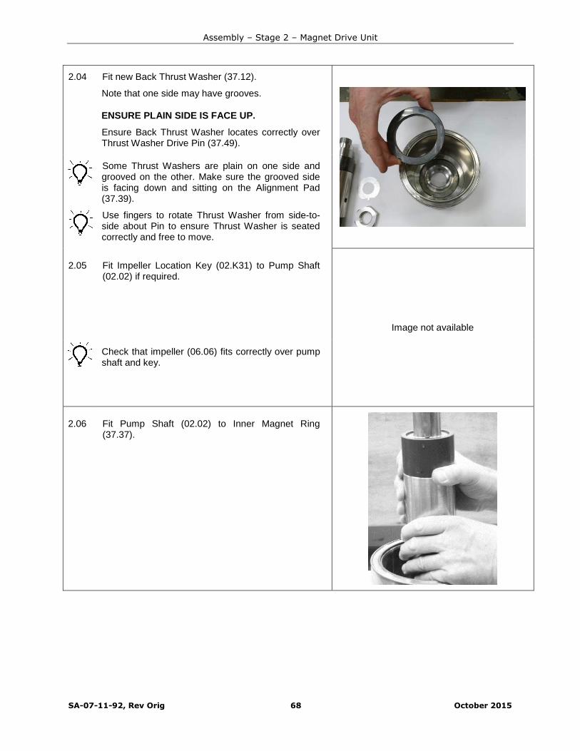
Assembly – Stage 2 – Magnet Drive Unit
SA-07-11-92, Rev Orig 68 October 2015
2.04 Fit new Back Thrust Washer (37.12).
Note that one side may have grooves.
ENSURE PLAIN SIDE IS FACE UP.
Ensure Back Thrust Washer locates correctly overThrust Washer Drive Pin (37.49).
Some Thrust Washers are plain on one side andgrooved on the other. Make sure the grooved sideis facing down and sitting on the Alignment Pad(37.39).
Use fingers to rotate Thrust Washer from side-to-side about Pin to ensure Thrust Washer is seatedcorrectly and free to move.
2.05 Fit Impeller Location Key (02.K31) to Pump Shaft(02.02) if required.
Image not available
Check that impeller (06.06) fits correctly over pumpshaft and key.
2.06 Fit Pump Shaft (02.02) to Inner Magnet Ring(37.37).
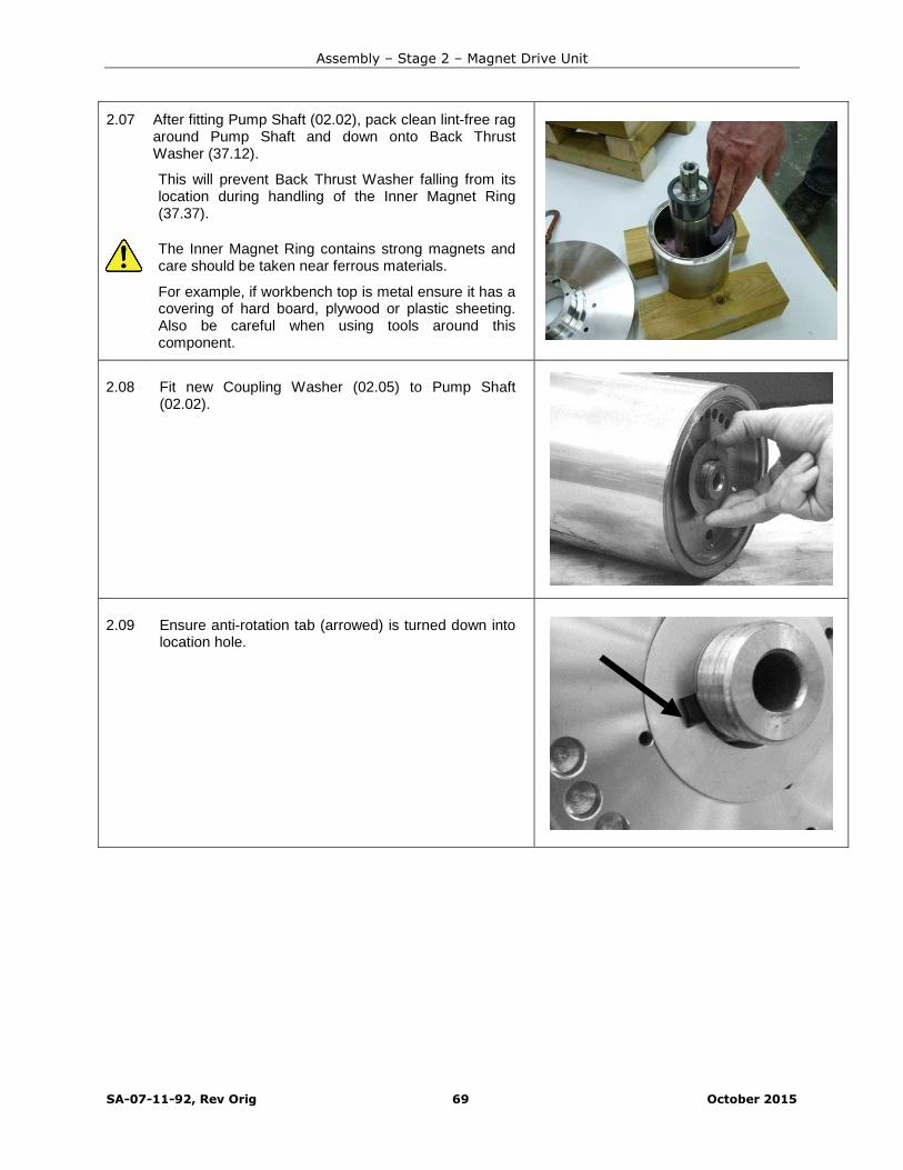
Assembly – Stage 2 – Magnet Drive Unit
SA-07-11-92, Rev Orig 69 October 2015
2.07 After fitting Pump Shaft (02.02), pack clean lint-free ragaround Pump Shaft and down onto Back ThrustWasher (37.12).
This will prevent Back Thrust Washer falling from itslocation during handling of the Inner Magnet Ring(37.37).
The Inner Magnet Ring contains strong magnets andcare should be taken near ferrous materials.
For example, if workbench top is metal ensure it has acovering of hard board, plywood or plastic sheeting.Also be careful when using tools around thiscomponent.
2.08 Fit new Coupling Washer (02.05) to Pump Shaft(02.02).
2.09 Ensure anti-rotation tab (arrowed) is turned down intolocation hole.

Assembly – Stage 2 – Magnet Drive Unit
SA-07-11-92, Rev Orig 70 October 2015
2.10 Fit Coupling Nut (02.36) to Pump Shaft (02.02).
Tighten finger tight.
EFT HAND THREAD
Tighten in an ANTI-CLOCKWISE direction
2.11 Turn over Inner Magnet Ring (37.37) and hold in avice with soft jaws fitted. Turn assembly anti-clockwiseuntil key (02.K31) locks against jaw before fullytightening vice.
Tighten Coupling Nut (02.36).
LEFT HAND THREAD
Tighten in an ANTI-CLOCKWISE direction
50mm AF
100 Nm (74 lbf-ft)
2.12 Use pry bar to turn up section of Coupling Washer(02.05) onto Coupling Nut (02.36).
2.13 Remove Pump Shaft with IMR attached from vice andplace on low level work surface.
Remove rag that was previously pushed betweenPump Shaft (02.02) and Inner Magnet Ring (37.37).

Assembly – Stage 2 – Magnet Drive Unit
SA-07-11-92, Rev Orig 71 October 2015
For ZeroLoss Containment Shell (20.20) the InnerMagnet Ring (37.37) must be supported either side ofthe protruding nut.
2.14 Fit Bush Holder (09.09) to Casing Plate (14.14) andalign off-set retention holes.
Fit Bush Holder retention Screws (14.S41) and tightenevenly by hand.
3/16" Hex
Fully tighten by hand.
2.15 Very carefully lower Casing Plate (14.14) completewith Bush Holder (09.09) over Pump Shaft (02.02).
Extreme care must be taken not to damage SiliconCarbide bearings as Bush Holder slides over PumpShaft.
Casing Plate with attached Bush Holder can weighmore that 25 kg (55 lbs).
2.16 Fit new Thrust Washer (07.07A) if required to ThrustWasher Holder (07.07).
Ensure it locates correctly over Thrust WasherLocation Pin (07.49).
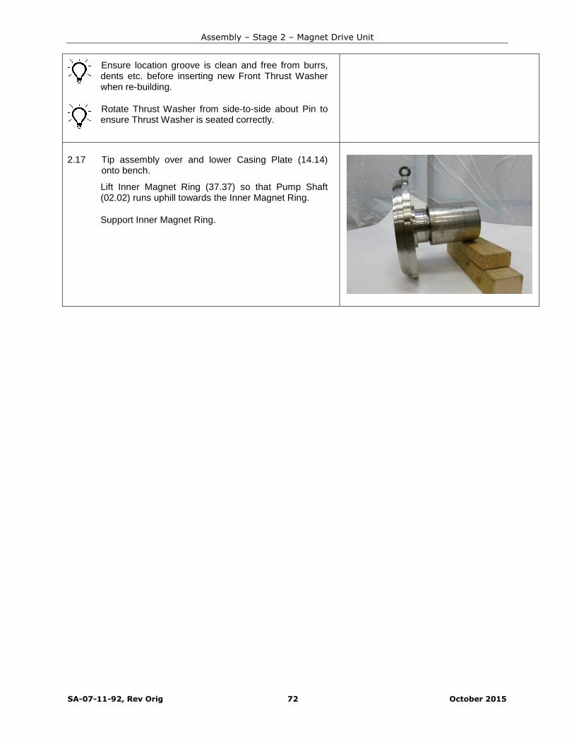
Assembly – Stage 2 – Magnet Drive Unit
SA-07-11-92, Rev Orig 72 October 2015
Ensure location groove is clean and free from burrs,dents etc. before inserting new Front Thrust Washerwhen re-building.
Rotate Thrust Washer from side-to-side about Pin toensure Thrust Washer is seated correctly.
2.17 Tip assembly over and lower Casing Plate (14.14)onto bench.
Lift Inner Magnet Ring (37.37) so that Pump Shaft(02.02) runs uphill towards the Inner Magnet Ring.
Support Inner Magnet Ring.
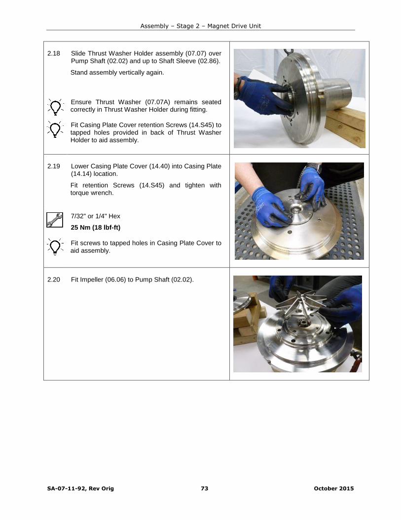
Assembly – Stage 2 – Magnet Drive Unit
SA-07-11-92, Rev Orig 73 October 2015
2.18 Slide Thrust Washer Holder assembly (07.07) overPump Shaft (02.02) and up to Shaft Sleeve (02.86).
Stand assembly vertically again.
Ensure Thrust Washer (07.07A) remains seatedcorrectly in Thrust Washer Holder during fitting.
Fit Casing Plate Cover retention Screws (14.S45) totapped holes provided in back of Thrust WasherHolder to aid assembly.
2.19 Lower Casing Plate Cover (14.40) into Casing Plate(14.14) location.
Fit retention Screws (14.S45) and tighten withtorque wrench.
7/32" or 1/4" Hex
25 Nm (18 lbf-ft)
Fit screws to tapped holes in Casing Plate Cover toaid assembly.
2.20 Fit Impeller (06.06) to Pump Shaft (02.02).

Assembly – Stage 2 – Magnet Drive Unit
SA-07-11-92, Rev Orig 74 October 2015
2.21 NO INDUCER OPTION
Fit Impeller Tab Washer (02.05A) and ImpellerFastener (02.03).
LEFT HAND THREAD
Do not fully tighten at this stage.
2.22 INDUCER OPTION
Occasionally an Inducer (76.01) will be fitted inplace of the Impeller Fastener.
Fit Stud (02.48A) into Inducer (76.01) and tightenuntil Stud bottoms in hole.
Fit Inducer together with Stud and Tab Washer(02.05A) to retain Impeller (06.06) to Pump Shaft(02.02).
LEFT HAND THREAD
Do not fully tighten at this stage.
2.23 Stand Coupling Housing (43.43) vertically on benchwith large flange uppermost.
Image not available
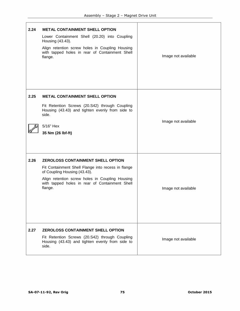
Assembly – Stage 2 – Magnet Drive Unit
SA-07-11-92, Rev Orig 75 October 2015
2.24 METAL CONTAINMENT SHELL OPTION
Lower Containment Shell (20.20) into CouplingHousing (43.43).
Align retention screw holes in Coupling Housingwith tapped holes in rear of Containment Shellflange. Image not available
2.25 METAL CONTAINMENT SHELL OPTION
Fit Retention Screws (20.S42) through CouplingHousing (43.43) and tighten evenly from side toside.
Image not available5/16” Hex
35 Nm (26 lbf-ft)
2.26 ZEROLOSS CONTAINMENT SHELL OPTION
Fit Containment Shell Flange into recess in flangeof Coupling Housing (43.43).
Align retention screw holes in Coupling Housingwith tapped holes in rear of Containment Shellflange. Image not available
2.27 ZEROLOSS CONTAINMENT SHELL OPTION
Fit Retention Screws (20.S42) through CouplingHousing (43.43) and tighten evenly from side toside.
Image not available
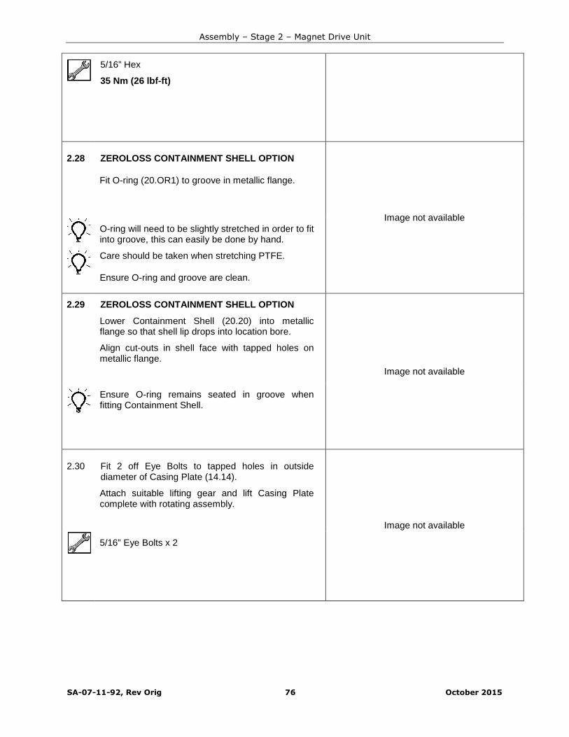
Assembly – Stage 2 – Magnet Drive Unit
SA-07-11-92, Rev Orig 76 October 2015
5/16” Hex
35 Nm (26 lbf-ft)
2.28 ZEROLOSS CONTAINMENT SHELL OPTION
Fit O-ring (20.OR1) to groove in metallic flange.
Image not availableO-ring will need to be slightly stretched in order to fitinto groove, this can easily be done by hand.
Care should be taken when stretching PTFE.
Ensure O-ring and groove are clean.
2.29 ZEROLOSS CONTAINMENT SHELL OPTION
Lower Containment Shell (20.20) into metallicflange so that shell lip drops into location bore.
Align cut-outs in shell face with tapped holes onmetallic flange.
Image not available
Ensure O-ring remains seated in groove whenfitting Containment Shell.
2.30 Fit 2 off Eye Bolts to tapped holes in outsidediameter of Casing Plate (14.14).
Attach suitable lifting gear and lift Casing Platecomplete with rotating assembly.
Image not available
5/16” Eye Bolts x 2
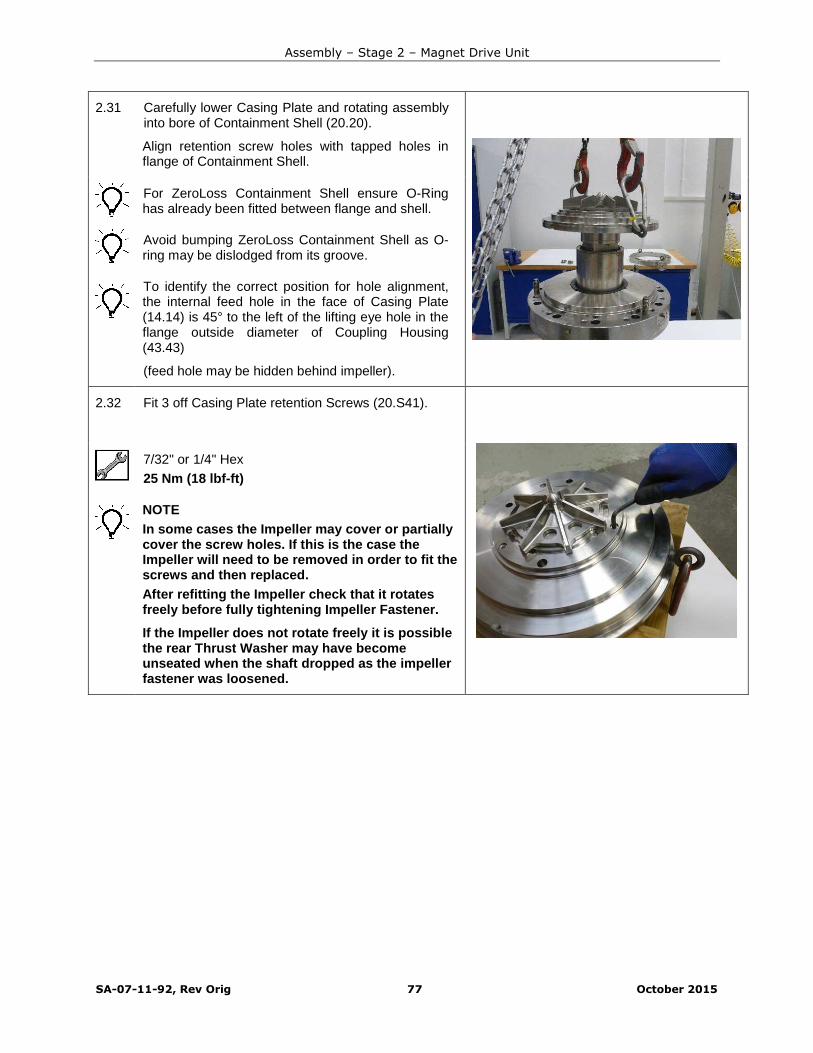
Assembly – Stage 2 – Magnet Drive Unit
SA-07-11-92, Rev Orig 77 October 2015
2.31 Carefully lower Casing Plate and rotating assemblyinto bore of Containment Shell (20.20).
Align retention screw holes with tapped holes inflange of Containment Shell.
For ZeroLoss Containment Shell ensure O-Ringhas already been fitted between flange and shell.
Avoid bumping ZeroLoss Containment Shell as O-ring may be dislodged from its groove.
To identify the correct position for hole alignment,the internal feed hole in the face of Casing Plate(14.14) is 45° to the left of the lifting eye hole in theflange outside diameter of Coupling Housing(43.43)
(feed hole may be hidden behind impeller).
2.32 Fit 3 off Casing Plate retention Screws (20.S41).
7/32" or 1/4" Hex
25 Nm (18 lbf-ft)
NOTE
In some cases the Impeller may cover or partiallycover the screw holes. If this is the case theImpeller will need to be removed in order to fit thescrews and then replaced.
After refitting the Impeller check that it rotatesfreely before fully tightening Impeller Fastener.
If the Impeller does not rotate freely it is possiblethe rear Thrust Washer may have becomeunseated when the shaft dropped as the impellerfastener was loosened.
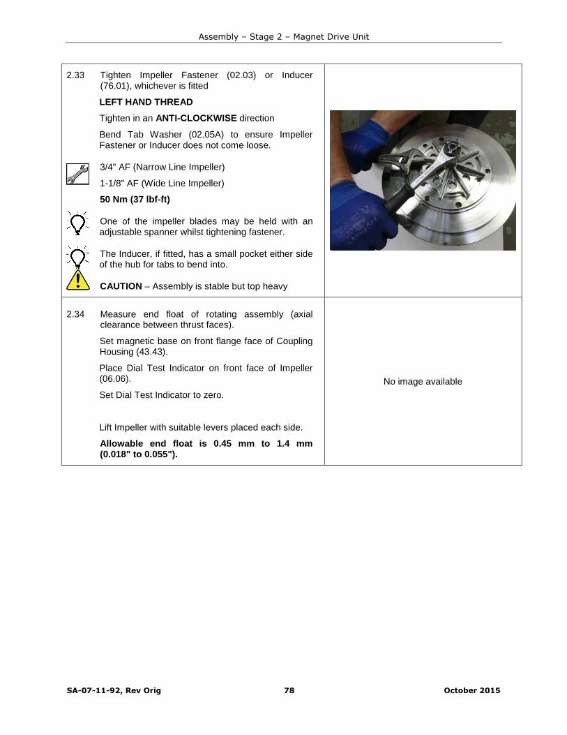
Assembly – Stage 2 – Magnet Drive Unit
SA-07-11-92, Rev Orig 78 October 2015
2.33 Tighten Impeller Fastener (02.03) or Inducer(76.01), whichever is fitted
LEFT HAND THREAD
Tighten in an ANTI-CLOCKWISE direction
Bend Tab Washer (02.05A) to ensure ImpellerFastener or Inducer does not come loose.
3/4" AF (Narrow Line Impeller)
1-1/8" AF (Wide Line Impeller)
50 Nm (37 lbf-ft)
One of the impeller blades may be held with anadjustable spanner whilst tightening fastener.
The Inducer, if fitted, has a small pocket either sideof the hub for tabs to bend into.
CAUTION – Assembly is stable but top heavy
2.34 Measure end float of rotating assembly (axialclearance between thrust faces).
Set magnetic base on front flange face of CouplingHousing (43.43).
Place Dial Test Indicator on front face of Impeller(06.06).
Set Dial Test Indicator to zero.
Lift Impeller with suitable levers placed each side.
Allowable end float is 0.45 mm to 1.4 mm(0.018" to 0.055").
No image available

Assembly – Stage 2 – Magnet Drive Unit
SA-07-11-92, Rev Orig 79 October 2015
2.35 Fit new Gasket (20.17) up to shoulder on flange ofContainment Shell (20.20).
Ensure Gasket seating face is free from dents andscratches etc.
Ensure Gasket lies within the diameter of seatingface or it may be damaged when Adaptor Ring(16.16) is fitted.
2.36 Fit new O-ring (14.OR3) into groove in outsidediameter of Casing Plate (14.14).
2.37 Fit new O-ring (14.OR2) up to FIRST shoulder onfront of Casing Plate (14.14).
Check O-ring is fitted on SMALLEST diameter ofCasing Plate.

Assembly – Stage 2 – Magnet Drive Unit
SA-07-11-92, Rev Orig 80 October 2015
2.38 Replace Jacking Screws (16.S51) with Eye Bolts.
Attach suitable lifting gear and lower Adaptor Ring(16.16) over Casing Plate (14.14) and up to frontface of Coupling Housing (43.43).
5/16” Eye Bolts x 2
Soft Mallet
Position so that vent hole in outer diameter ofCasing Plate lines up with vent flange on AdaptorRing.
Adaptor Ring will need to be tapped on with a softMallet due to friction of O-ring (14.OR3).
Be careful not to pinch Gasket (20.17).
2.39 Fit 12 off Retention Screws (43.S55) and tightenevenly from side to side.
1/2” Hex
125 Nm (92 lbf-ft)
Gasket (20.17) is fully seated when there is nolonger a gap between Adaptor Ring (16.16) andCoupling Housing (43.43).
CAUTION – Assembly is stable but top heavy.
2.40 Attach suitable lifting gear to eye Bolts alreadyfitted to Adaptor Ring (16.16).
Lift Magnet Drive Unit into the vertical position.
5/16” Eye Bolts x 2
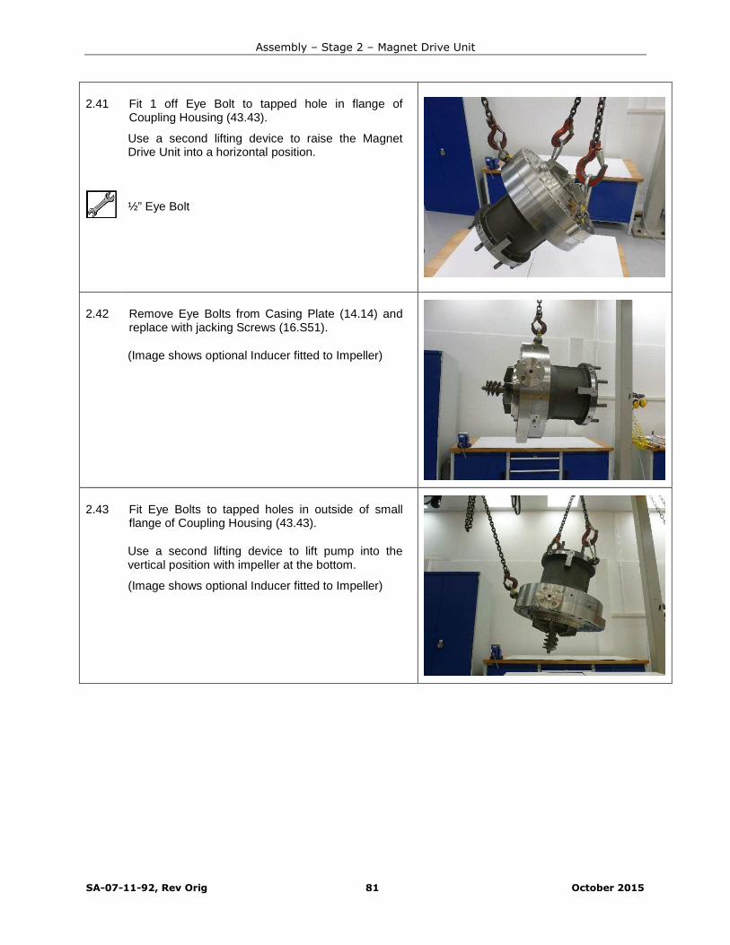
Assembly – Stage 2 – Magnet Drive Unit
SA-07-11-92, Rev Orig 81 October 2015
2.41 Fit 1 off Eye Bolt to tapped hole in flange ofCoupling Housing (43.43).
Use a second lifting device to raise the MagnetDrive Unit into a horizontal position.
½” Eye Bolt
2.42 Remove Eye Bolts from Casing Plate (14.14) andreplace with jacking Screws (16.S51).
(Image shows optional Inducer fitted to Impeller)
2.43 Fit Eye Bolts to tapped holes in outside of smallflange of Coupling Housing (43.43).
Use a second lifting device to lift pump into thevertical position with impeller at the bottom.
(Image shows optional Inducer fitted to Impeller)
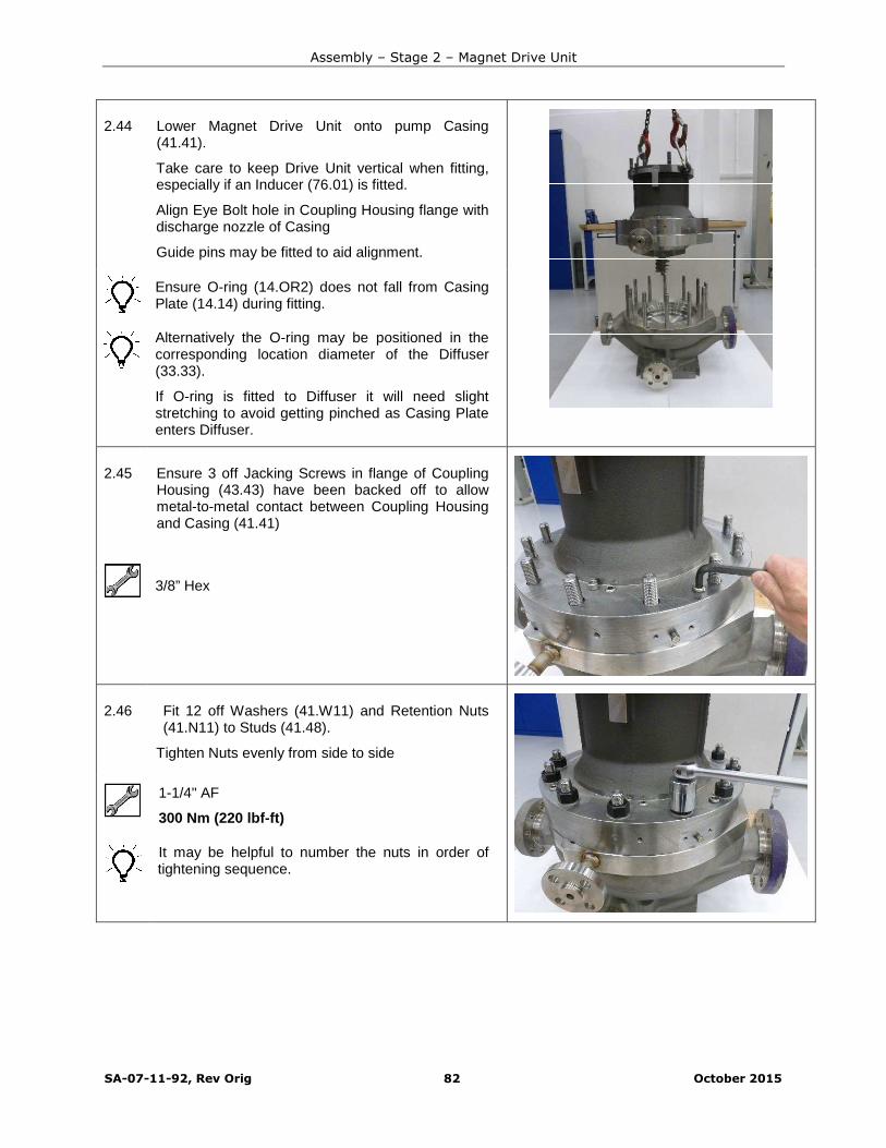
Assembly – Stage 2 – Magnet Drive Unit
SA-07-11-92, Rev Orig 82 October 2015
2.44 Lower Magnet Drive Unit onto pump Casing(41.41).
Take care to keep Drive Unit vertical when fitting,especially if an Inducer (76.01) is fitted.
Align Eye Bolt hole in Coupling Housing flange withdischarge nozzle of Casing
Guide pins may be fitted to aid alignment.
Ensure O-ring (14.OR2) does not fall from CasingPlate (14.14) during fitting.
Alternatively the O-ring may be positioned in thecorresponding location diameter of the Diffuser(33.33).
If O-ring is fitted to Diffuser it will need slightstretching to avoid getting pinched as Casing Plateenters Diffuser.
2.45 Ensure 3 off Jacking Screws in flange of CouplingHousing (43.43) have been backed off to allowmetal-to-metal contact between Coupling Housingand Casing (41.41)
3/8” Hex
2.46 Fit 12 off Washers (41.W11) and Retention Nuts(41.N11) to Studs (41.48).
Tighten Nuts evenly from side to side
1-1/4" AF
300 Nm (220 lbf-ft)
It may be helpful to number the nuts in order oftightening sequence.
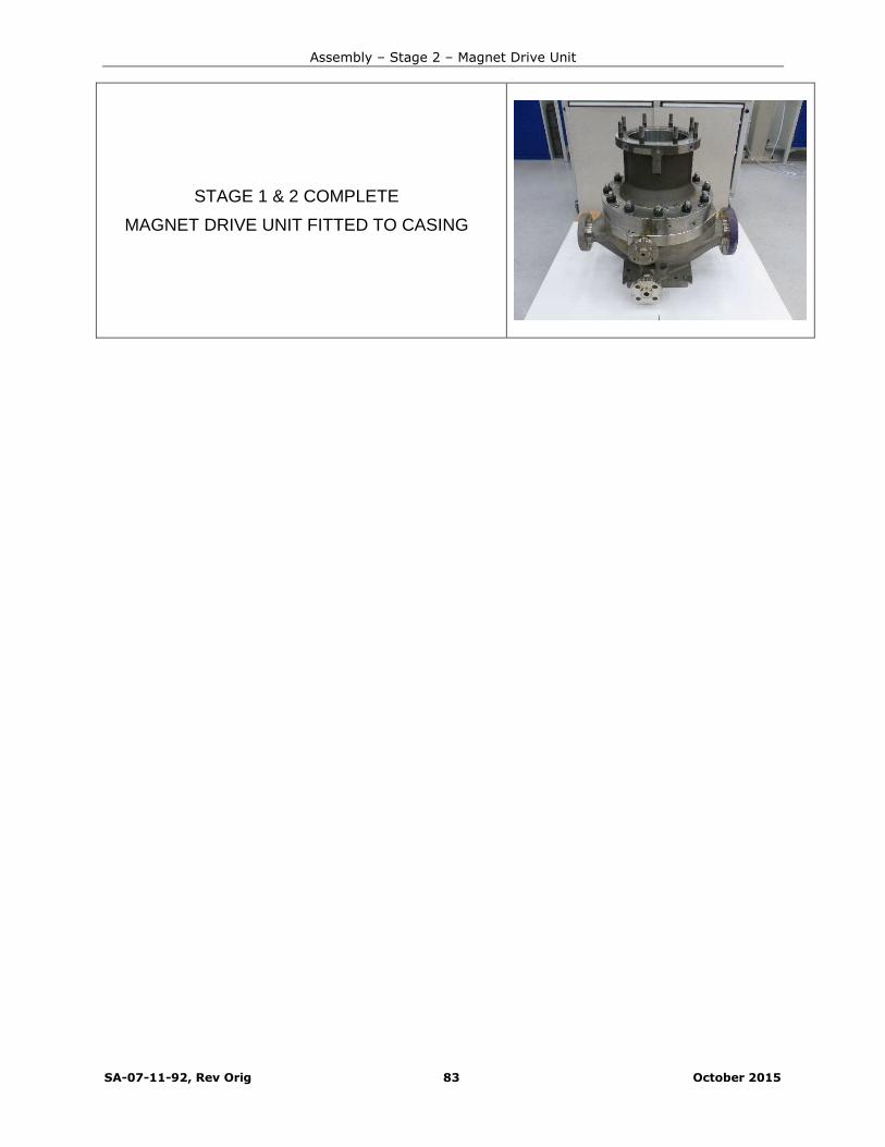
Assembly – Stage 2 – Magnet Drive Unit
SA-07-11-92, Rev Orig 83 October 2015
STAGE 1 & 2 COMPLETE
MAGNET DRIVE UNIT FITTED TO CASING

SA-07-11-92, Rev Orig 84 October 2015
Assembly - Stage 3 – Motor & Motor Support (Close Coupled)
3.01 Fit taper ring part of Drive Adaptor (52.52) overmotor shaft.
Ensure taper is correct way round to match taper onDrive Adaptor body.
Apply anti-seize compound to bore of taper ring.
3.02 Fit Drive Adaptor to motor shaft.
Push Drive Adaptor (52.52) on to motor shaft.
Shaft end must bottom out in bore of Drive Adaptorfor correct axial positioning.
Use a soft mallet to tap the end of Adaptor toensure shaft has bottomed.
Apply anti-seize compound to motor shaft.
3.03 Fit Draw Screws (52.S42) and tighten evenly todraw taper ring towards flange.
This will cause Drive Adaptor to grip motor shaft.
Leave final tightening for next step.
IEC Motors – 8 mm Hex
NEMA 143TC to 215TC – 7/32” Hex
NEMA 254TC to 365TSC – 5/16” Hex
Apply anti-seize compound to thread of DrawScrews.
A large screw driver or similar tool can be usedbehind the flange between one of the screws andthe Drive Adaptor body to prevent the Drive Adaptorfrom turning

Assembly – Stage 3 – Motor & Motor Support
SA-07-11-92, Rev Orig 85 October 2015
3.04 Attach magnetic base to front face of motor tocheck run-out of Drive Adaptor (52.52).
Set Dial Test Indicator to run in front bore which isthe location for Outer Magnet Ring (51.51).
Tighten Retention Screws (52.S42) in a sequencethat will keep run-out within limits.
Maximum allowable run-out 0.075 mm(0.003”)
IEC 90 to 250 – 8 mm Hex – 75 Nm (55 lbf-ft)
143TC to 215TC – 7/32” Hex – 35 Nm (26 lbf-ft)
254TC to 365 TSC – 5/16” Hex – 60 Nm (44 lbf-ft)
3.05 Fit 2 off Eye Bolts and suitable lifting gear to tappedholes in any two adjacent webs of Motor Adaptor(45.45).
2 x 5/8” Eye Bolts for NEMA Motors
2 x M16 Eye Bolts for IEC motors
3.06 NEMA Motors
NEMA motors are face mounted, an Adaptor Plate(45.16) will always be mounted to the front face ofthe NEMA motor.
Fit Adaptor Plate (45.16) to front face of motor.
3.07 NEMA Motors
Fit retention Screws (45.S42) and tighten downevenly from side to side.
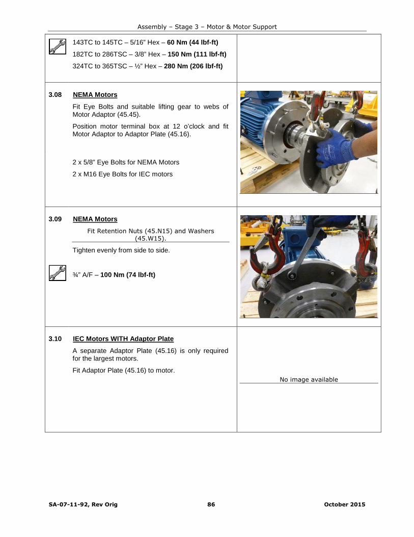
Assembly – Stage 3 – Motor & Motor Support
SA-07-11-92, Rev Orig 86 October 2015
143TC to 145TC – 5/16” Hex – 60 Nm (44 lbf-ft)
182TC to 286TSC – 3/8” Hex – 150 Nm (111 lbf-ft)
324TC to 365TSC – ½” Hex – 280 Nm (206 lbf-ft)
3.08 NEMA Motors
Fit Eye Bolts and suitable lifting gear to webs ofMotor Adaptor (45.45).
Position motor terminal box at 12 o’clock and fitMotor Adaptor to Adaptor Plate (45.16).
2 x 5/8” Eye Bolts for NEMA Motors
2 x M16 Eye Bolts for IEC motors
3.09 NEMA Motors
Fit Retention Nuts (45.N15) and Washers(45.W15).
Tighten evenly from side to side.
¾” A/F – 100 Nm (74 lbf-ft)
3.10 IEC Motors WITH Adaptor Plate
A separate Adaptor Plate (45.16) is only requiredfor the largest motors.
Fit Adaptor Plate (45.16) to motor.
No image available

Assembly – Stage 3 – Motor & Motor Support
SA-07-11-92, Rev Orig 87 October 2015
3.11 IEC Motors WITH Adaptor Plate
Fit retention Screws (45.S42) and Washers(45.W15).
Tighten down evenly from side to side.
250 Frame motor with require addition of Nuts(45.N15) and Washers (45.W15).
No image available
24 mm AF
185 Nm (136 lbf-ft)
3.12 IEC Motors WITH Adaptor Plate
Fit 2 off Eye Bolts and suitable lifting gear to anyadjacent webs of Motor Adaptor (45.45).
Position motor terminal box at 12 o’clock.
Fit Motor Adaptor to Adaptor Plate (45.16).
M16 Eye Bolts x 2
3.13 IEC Motors WITH Adaptor Plate
Fit Retention Nuts (45.N15) and Washers(45.W15).
Tighten evenly from side to side.
15/16” AF
200 Nm (147 lbf-ft)
3.14 IEC Motors WITHOUT Adaptor Plate
IEC motors are flange mounted, in most cases anAdaptor Plate will not be required.
Fit 2 off Eye Bolts and suitable lifting gear to anyadjacent webs of Motor Adaptor (45.45).
Position motor terminal box at 12 o’clock.
Fit Motor Adaptor (45.45) directly to motor flange.
No image available
M16 Eye Bolts x 2
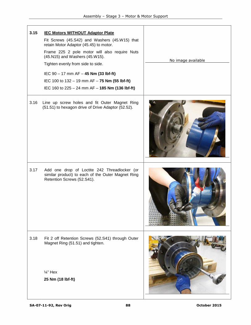
Assembly – Stage 3 – Motor & Motor Support
SA-07-11-92, Rev Orig 88 October 2015
3.15 IEC Motors WITHOUT Adaptor Plate
Fit Screws (45.S42) and Washers (45.W15) thatretain Motor Adaptor (45.45) to motor.
Frame 225 2 pole motor will also require Nuts(45.N15) and Washers (45.W15).
Tighten evenly from side to side.No image available
IEC 90 – 17 mm AF – 45 Nm (33 lbf-ft)
IEC 100 to 132 – 19 mm AF – 75 Nm (55 lbf-ft)
IEC 160 to 225 – 24 mm AF – 185 Nm (136 lbf-ft)
3.16 Line up screw holes and fit Outer Magnet Ring(51.51) to hexagon drive of Drive Adaptor (52.52).
3.17 Add one drop of Loctite 242 Threadlocker (orsimilar product) to each of the Outer Magnet RingRetention Screws (52.S41).
3.18 Fit 2 off Retention Screws (52.S41) through OuterMagnet Ring (51.51) and tighten.
¼” Hex
25 Nm (18 lbf-ft)
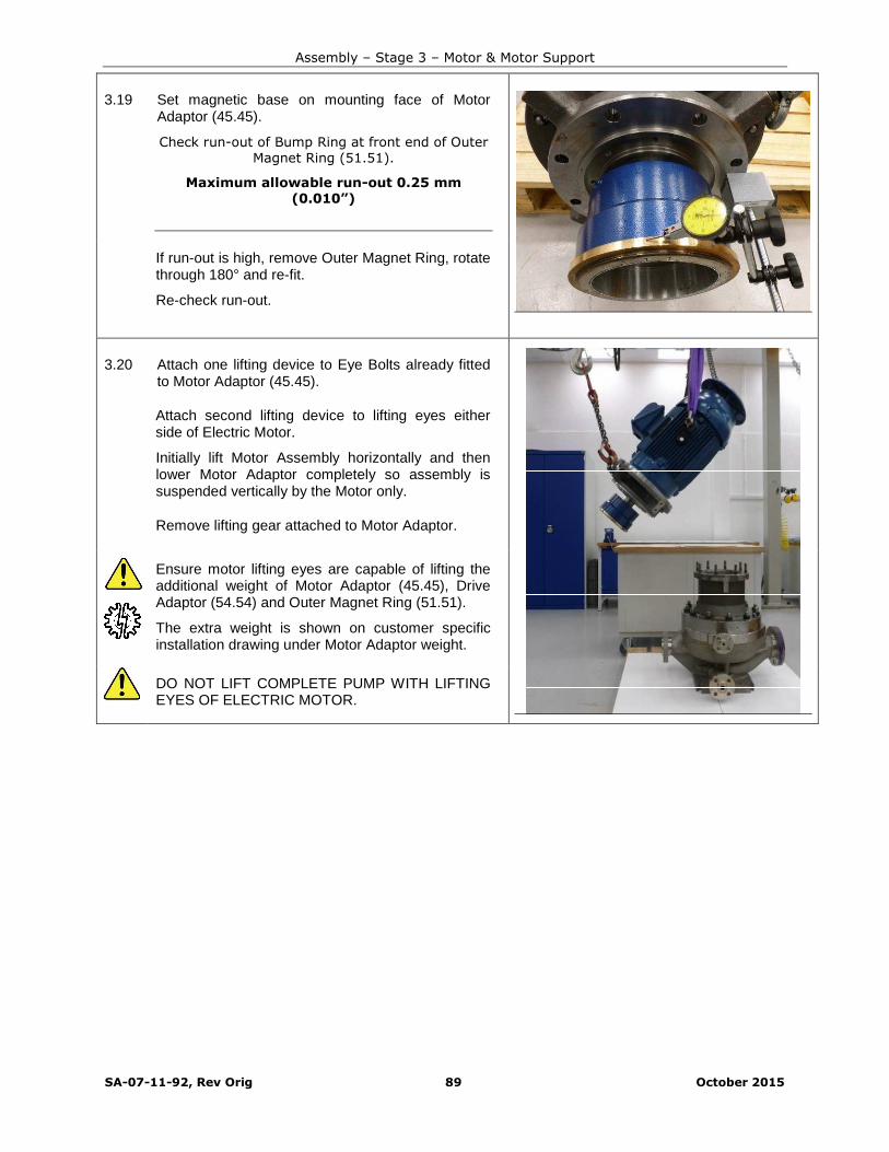
Assembly – Stage 3 – Motor & Motor Support
SA-07-11-92, Rev Orig 89 October 2015
3.19 Set magnetic base on mounting face of MotorAdaptor (45.45).
Check run-out of Bump Ring at front end of OuterMagnet Ring (51.51).
Maximum allowable run-out 0.25 mm(0.010”)
If run-out is high, remove Outer Magnet Ring, rotatethrough 180° and re-fit.
Re-check run-out.
3.20 Attach one lifting device to Eye Bolts already fittedto Motor Adaptor (45.45).
Attach second lifting device to lifting eyes eitherside of Electric Motor.
Initially lift Motor Assembly horizontally and thenlower Motor Adaptor completely so assembly issuspended vertically by the Motor only.
Remove lifting gear attached to Motor Adaptor.
Ensure motor lifting eyes are capable of lifting theadditional weight of Motor Adaptor (45.45), DriveAdaptor (54.54) and Outer Magnet Ring (51.51).
The extra weight is shown on customer specificinstallation drawing under Motor Adaptor weight.
DO NOT LIFT COMPLETE PUMP WITH LIFTINGEYES OF ELECTRIC MOTOR.
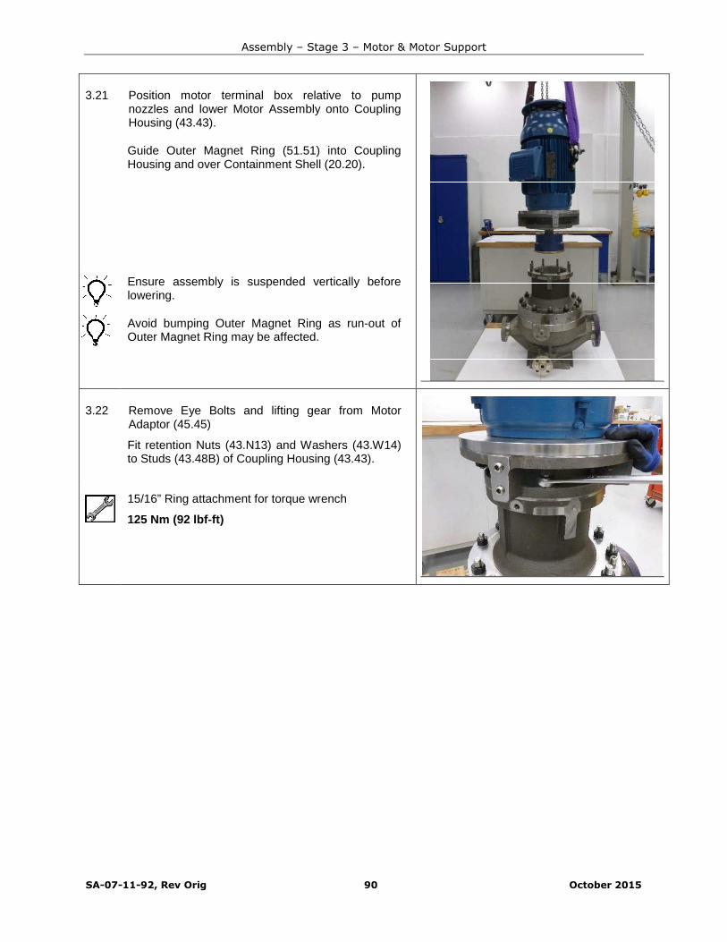
Assembly – Stage 3 – Motor & Motor Support
SA-07-11-92, Rev Orig 90 October 2015
3.21 Position motor terminal box relative to pumpnozzles and lower Motor Assembly onto CouplingHousing (43.43).
Guide Outer Magnet Ring (51.51) into CouplingHousing and over Containment Shell (20.20).
Ensure assembly is suspended vertically beforelowering.
Avoid bumping Outer Magnet Ring as run-out ofOuter Magnet Ring may be affected.
3.22 Remove Eye Bolts and lifting gear from MotorAdaptor (45.45)
Fit retention Nuts (43.N13) and Washers (43.W14)to Studs (43.48B) of Coupling Housing (43.43).
15/16” Ring attachment for torque wrench
125 Nm (92 lbf-ft)
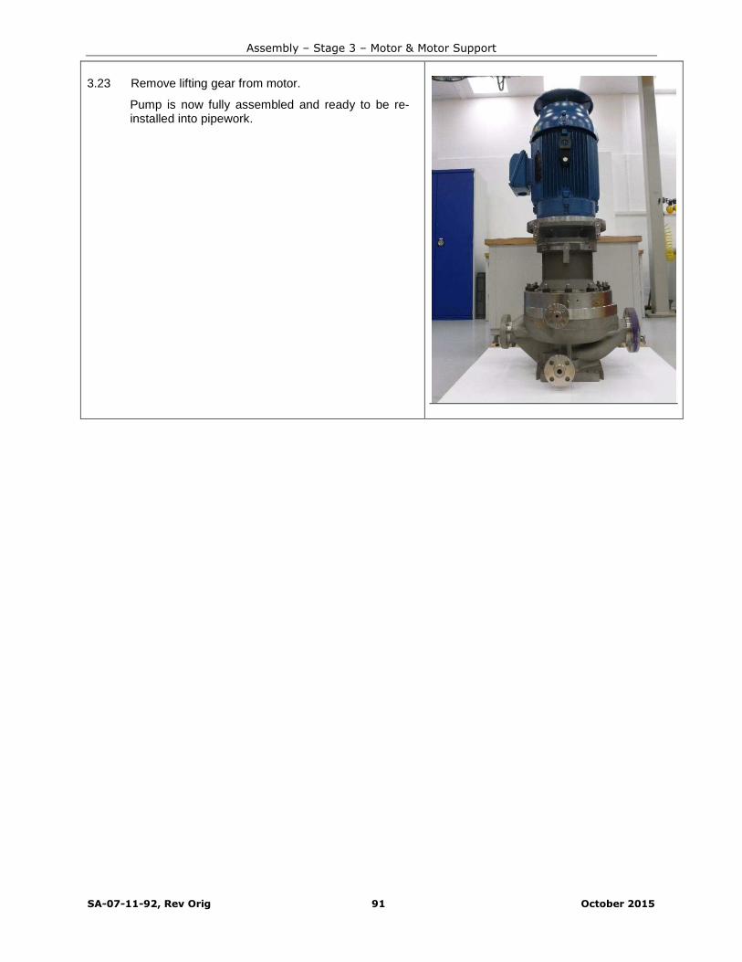
Assembly – Stage 3 – Motor & Motor Support
SA-07-11-92, Rev Orig 91 October 2015
3.23 Remove lifting gear from motor.
Pump is now fully assembled and ready to be re-installed into pipework.

SA-07-11-92, Rev Orig 92 October 2015
Assembly - Stage 4 – Re-Install Pump
4.01 Fit lifting lugs (98.98) to motor Adaptor (45.45) withHigh Tensile Retention Screws (98.S11) andWashers (98.W11).
Each new pump is furnished with the above liftingequipment.
2 off Lifting Lugs for pumps up to 750 kg (1650 lbs).
4 off Lifting Lugs for pumps over 750 kg (1650 lbs).
Lifting Lugs are only certified to the weight markedwhen used with Retention Screws supplied.
15/16” AF for NEMA motors
24 mm AF for IEC motors
125 Nm (92 lbf-ft) (NEMA & IEC)
4.02 Complete pump should be lifted with Lifting Lugs(98.98) that were originally supplied with the pump.
Fit suitable lifting gear to Lifting Lugs (98.98) andtake up any slack to prevent toppling of pump.
Remove fixing down screws if used.
Lift pump away and re-fit to pipework.
Re-fit orifice plate if necessary.
Securely fasten pump to suitable base duringtransport.
4.03 Remove Retention Screws (98.S11), Washers(98.W11) and Lifting Lugs (98.98) from MotorAdaptor (45.45).
15/16” AF for NEMA motors
24 mm AF for IEC motors

Assembly – Stage 4 – Re-Install Pump
SA-07-11-92, Rev Orig 93 October 2015
4.04 Re-fit grub screws (45.S53) to webs of MotorAdaptor (45.45).
This will prevent corrosion of retention holes forLifting Lug fasteners.
5/16” Hex
Hand tight
Pump is now ready for commissioning
Refer to Installation & Operating Manual for correct venting and start-up procedure.

SA-07-11-92, Rev Orig 94 October 2015
REPLACEMENT OF BUSHES &THRUST PAD
Whilst Silicon Carbide has excellent wear resistance, it is brittle and care must be taken inhandling this material. Wear eye protection to guard against fracturing of Silicon Carbidebearings.
If visibly worn or damaged it is strongly recommended that Bushes and Pad are renewed beforere-assembling Pump. Alternatively a complete new assembly can be purchased from Sundyne ortheir authorised representatives.
Read the whole of this Section thoroughly before proceeding with Bush and Pad replacement.
Guard against combustion of product residue on components.
Wear suitable protective clothing and heat resistant gloves at all times while handling hotcomponents. Do not handle hot Bush Holder Sleeve (09.09) even when wearing heat resistantgloves, only use metal tongs to manoeuvre Sleeve.
1.01 Replacement Silicon Carbide Bushes and Thrust Pad must be at a temperature of at least 15°Cbefore fitting to Bush Holder.
1.02 To remove existing Silicon Carbide Bushes and Thrust Pad, place Bush Holder (09.09) in hightemperature industrial oven or on industrial gas ring and heat to 300°C (572°F).
1.03 Stand Bush Holder (09.09) on metal blocks in sucha way that Bush and Back Thrust Pad will be free todrop out when required temperature is reached.
For this method to work properly Bush HolderSleeve must be exactly vertical.
If using an industrial gas ring, check Bush HolderSleeve frequently with a temperature touch probe toensure overheating does not occur.
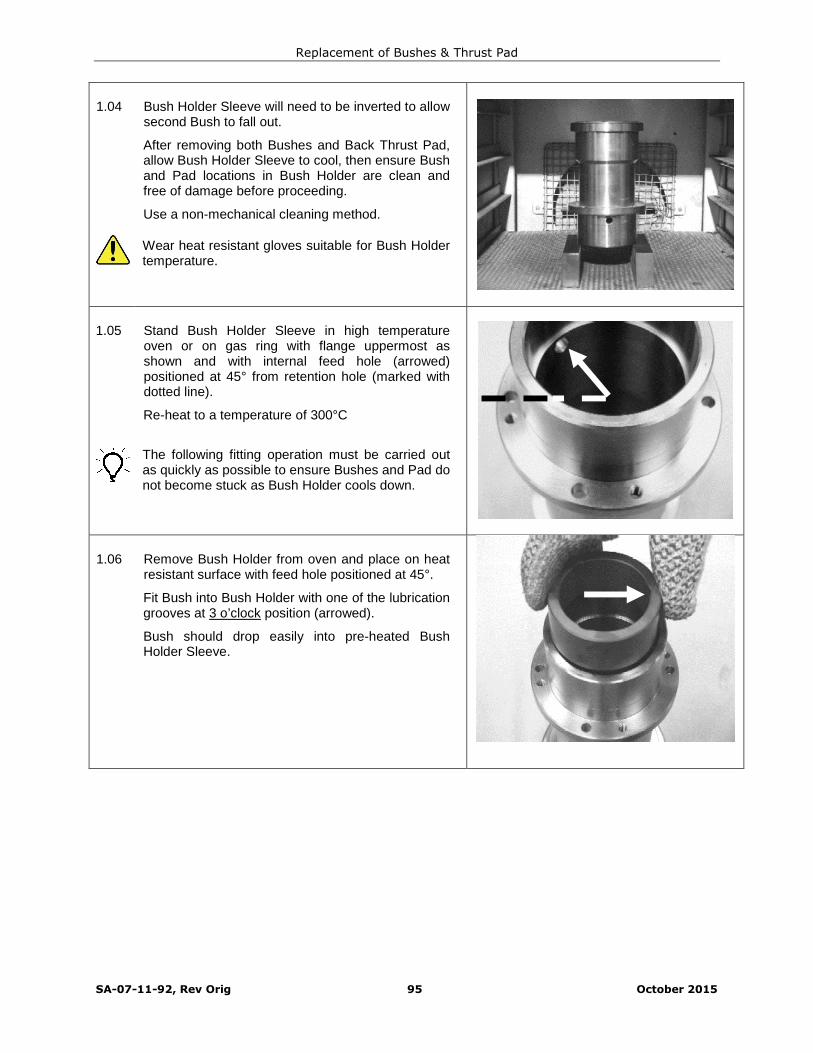
Replacement of Bushes & Thrust Pad
SA-07-11-92, Rev Orig 95 October 2015
1.04 Bush Holder Sleeve will need to be inverted to allowsecond Bush to fall out.
After removing both Bushes and Back Thrust Pad,allow Bush Holder Sleeve to cool, then ensure Bushand Pad locations in Bush Holder are clean andfree of damage before proceeding.
Use a non-mechanical cleaning method.
Wear heat resistant gloves suitable for Bush Holdertemperature.
1.05 Stand Bush Holder Sleeve in high temperatureoven or on gas ring with flange uppermost asshown and with internal feed hole (arrowed)positioned at 45° from retention hole (marked withdotted line).
Re-heat to a temperature of 300°C
The following fitting operation must be carried outas quickly as possible to ensure Bushes and Pad donot become stuck as Bush Holder cools down.
1.06 Remove Bush Holder from oven and place on heatresistant surface with feed hole positioned at 45°.
Fit Bush into Bush Holder with one of the lubricationgrooves at 3 o’clock position (arrowed).
Bush should drop easily into pre-heated BushHolder Sleeve.

Replacement of Bushes & Thrust Pad
SA-07-11-92, Rev Orig 96 October 2015
1.07 Hold Bush in place with one hand using thin metalstrip.
Grasp body of Bush Holder Sleeve with the otherhand using metal tongs or appropriate heatresistant gloves.
1.08 Turn assembly over whilst holding first Bush inplace.
Lower assembly carefully and slide out thin metalstrip.
1.09 Quickly fit second Bush with lubrication grooves inBush at 9 o’clock position (arrow ‘A’) in line with Pin(09.49C – arrow ‘B’).
Quickly fit Thrust Pad with lubrication groovesuppermost.
Bush and Pad should drop easily into Bush Holder.
If Bush or Pad become stuck as Bush Holder coolsdown, reapply heat to Bush Holder.
‘A’
‘B’

Replacement of Bushes & Thrust Pad
SA-07-11-92, Rev Orig 97 October 2015
1.10 Carefully place weight on Back Thrust Pad.
Allow assembly to cool in draught free atmosphere.Do not attempt to artificially accelerate cooling asthis may result in damage to Bushes or Pad.
Check temperature of assembly with temperaturetouch probe.
When cool, visually inspect Bushes and Pad toensure they are correctly seated in their locations.
Also check that there are no cracks or damage toBushes and Pad.
Dimensions of weight should be Ø95 mm (Ø3.75”)max x Ø80 mm (Ø3.15”) min x 40 to 50 mm (1.5” to2”) high.

Installation and Operation Manual
SA-07-11-92, Rev Orig 98 October 2015
Quick Reference Torque Settings
ReferenceNumber
Description Tool SizeThread
Size
LeftHand
Thread
Torque Setting
Nm lbf-ft
02.03 Fastener (Impeller Narrow Line) 3/4" AF
Deep Socket1/2" UNF LH 50 37
02.03 Fastener (Impeller Wide Line) 1-1/8" AF
Deep Socket1/2" UNF LH 50 37
02.36Retention Nut (Inner MagnetRing) 50mm AF M30 x2
LH100 74
14.S41 Retention Screw (Bush Holder) 3/16"
Hex Key1/4" UNC Fully hand tighten
14.S45 Retention Screw (Cover Plate)7/32" or 1/4"
Hex Key5/16" UNC 25 18
16.S51 Jack Screw (Coupling Housing)5/16”
Hex Key5/8” UNC By feel
20.S41Retention Screw (Casing PlateCover)
7/32" or 1/4"Hex Key
5/16" UNC 25 18
20.S42Retention Screw (CouplingHousing)
5/16”
Hex Key3/8" UNC 35 26
41.N11 Retention Nut, Heavy (Casing) 1-1/4" AF 3/4" UNC 300 220
43.N13 Retention Nut (Motor Adaptor) 15/16" AF 5/8" UNC 125 92
43.S12 Jack Screw (Casing)3/8”
Hex Key¾” UNC By feel
43.S52 Jack Screw (Containment Shell)5/16”
Hex Key5/8” UNC By feel
43.S55 Retention Screw (Adaptor Ring)½”
Hex Key5/8” UNC 125 92
45.N15
Retention Nut (Motor Adaptor)
NEMA ¾” AF ½” UNC 100 74
IEC (WITHOUT Adaptor Plate)
17 AF
90 FrameMotor
M10 45 33
19 AF
100 to 132Frame Motor
M12 75 55
24 AF
160 to 225Frame Motor
M16 184 136
IEC (WITH Adaptor Plate) 15/16" AF 5/8" UNC 200 147
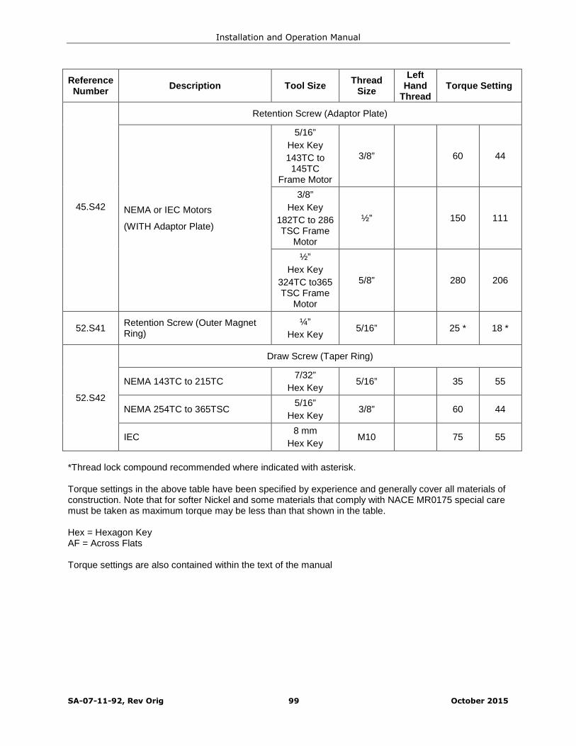
Installation and Operation Manual
SA-07-11-92, Rev Orig 99 October 2015
ReferenceNumber
Description Tool SizeThread
Size
LeftHand
ThreadTorque Setting
45.S42
Retention Screw (Adaptor Plate)
NEMA or IEC Motors
(WITH Adaptor Plate)
5/16”
Hex Key
143TC to145TC
Frame Motor
3/8” 60 44
3/8”
Hex Key
182TC to 286TSC Frame
Motor
½” 150 111
½”
Hex Key
324TC to365TSC Frame
Motor
5/8” 280 206
52.S41Retention Screw (Outer MagnetRing)
¼”
Hex Key5/16” 25 * 18 *
52.S42
Draw Screw (Taper Ring)
NEMA 143TC to 215TC7/32”
Hex Key5/16” 35 55
NEMA 254TC to 365TSC5/16”
Hex Key3/8” 60 44
IEC8 mm
Hex KeyM10 75 55
*Thread lock compound recommended where indicated with asterisk.
Torque settings in the above table have been specified by experience and generally cover all materials ofconstruction. Note that for softer Nickel and some materials that comply with NACE MR0175 special caremust be taken as maximum torque may be less than that shown in the table.
Hex = Hexagon KeyAF = Across Flats
Torque settings are also contained within the text of the manual
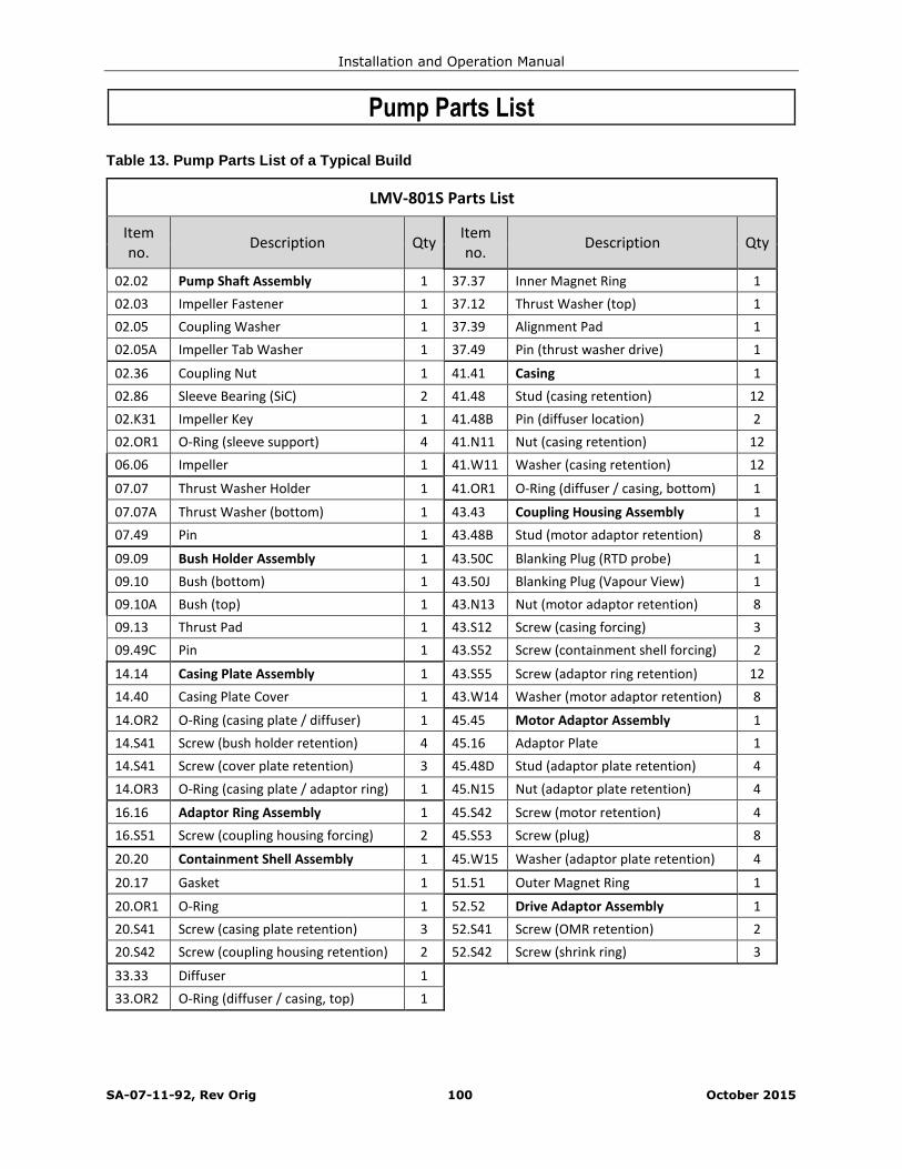
Installation and Operation Manual
SA-07-11-92, Rev Orig 100 October 2015
Pump Parts List
Table 13. Pump Parts List of a Typical Build
LMV-801S Parts List
Itemno.
Description QtyItemno.
Description Qty
02.02 Pump Shaft Assembly 1 37.37 Inner Magnet Ring 1
02.03 Impeller Fastener 1 37.12 Thrust Washer (top) 1
02.05 Coupling Washer 1 37.39 Alignment Pad 1
02.05A Impeller Tab Washer 1 37.49 Pin (thrust washer drive) 1
02.36 Coupling Nut 1 41.41 Casing 1
02.86 Sleeve Bearing (SiC) 2 41.48 Stud (casing retention) 12
02.K31 Impeller Key 1 41.48B Pin (diffuser location) 2
02.OR1 O-Ring (sleeve support) 4 41.N11 Nut (casing retention) 12
06.06 Impeller 1 41.W11 Washer (casing retention) 12
07.07 Thrust Washer Holder 1 41.OR1 O-Ring (diffuser / casing, bottom) 1
07.07A Thrust Washer (bottom) 1 43.43 Coupling Housing Assembly 1
07.49 Pin 1 43.48B Stud (motor adaptor retention) 8
09.09 Bush Holder Assembly 1 43.50C Blanking Plug (RTD probe) 1
09.10 Bush (bottom) 1 43.50J Blanking Plug (Vapour View) 1
09.10A Bush (top) 1 43.N13 Nut (motor adaptor retention) 8
09.13 Thrust Pad 1 43.S12 Screw (casing forcing) 3
09.49C Pin 1 43.S52 Screw (containment shell forcing) 2
14.14 Casing Plate Assembly 1 43.S55 Screw (adaptor ring retention) 12
14.40 Casing Plate Cover 1 43.W14 Washer (motor adaptor retention) 8
14.OR2 O-Ring (casing plate / diffuser) 1 45.45 Motor Adaptor Assembly 1
14.S41 Screw (bush holder retention) 4 45.16 Adaptor Plate 1
14.S41 Screw (cover plate retention) 3 45.48D Stud (adaptor plate retention) 4
14.OR3 O-Ring (casing plate / adaptor ring) 1 45.N15 Nut (adaptor plate retention) 4
16.16 Adaptor Ring Assembly 1 45.S42 Screw (motor retention) 4
16.S51 Screw (coupling housing forcing) 2 45.S53 Screw (plug) 8
20.20 Containment Shell Assembly 1 45.W15 Washer (adaptor plate retention) 4
20.17 Gasket 1 51.51 Outer Magnet Ring 1
20.OR1 O-Ring 1 52.52 Drive Adaptor Assembly 1
20.S41 Screw (casing plate retention) 3 52.S41 Screw (OMR retention) 2
20.S42 Screw (coupling housing retention) 2 52.S42 Screw (shrink ring) 3
33.33 Diffuser 1
33.OR2 O-Ring (diffuser / casing, top) 1
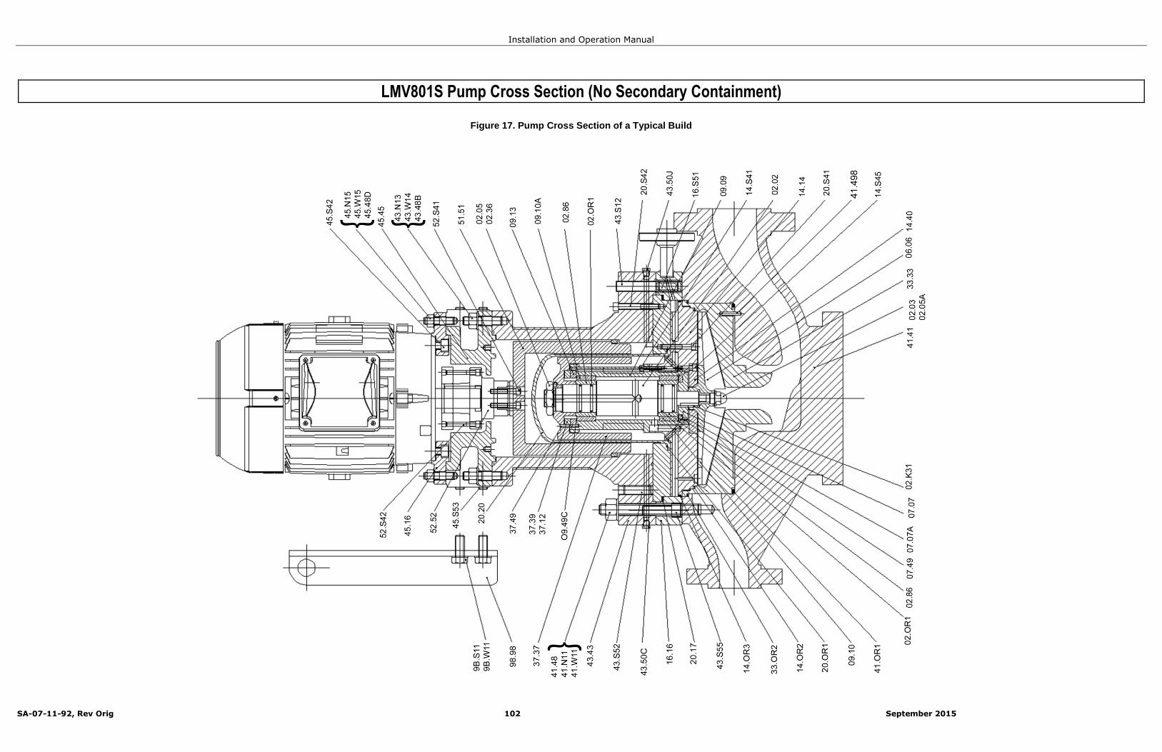
Installation and Operation Manual
SA-07-11-92, Rev Orig 102 September 2015
LMV801S Pump Cross Section (No Secondary Containment)
Figure 17. Pump Cross Section of a Typical Build
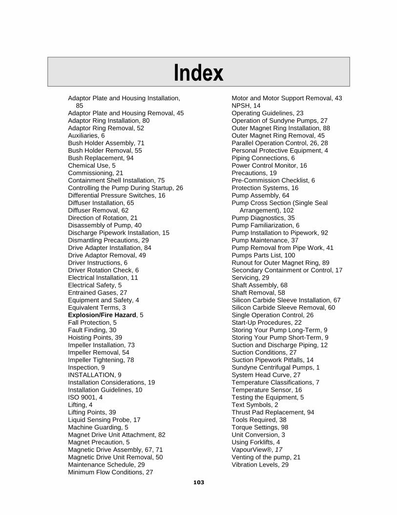
103
IndexAdaptor Plate and Housing Installation,
85Adaptor Plate and Housing Removal, 45Adaptor Ring Installation, 80Adaptor Ring Removal, 52Auxiliaries, 6Bush Holder Assembly, 71Bush Holder Removal, 55Bush Replacement, 94Chemical Use, 5Commissioning, 21Containment Shell Installation, 75Controlling the Pump During Startup, 26Differential Pressure Switches, 16Diffuser Installation, 65Diffuser Removal, 62Direction of Rotation, 21Disassembly of Pump, 40Discharge Pipework Installation, 15Dismantling Precautions, 29Drive Adapter Installation, 84Drive Adaptor Removal, 49Driver Instructions, 6Driver Rotation Check, 6Electrical Installation, 11Electrical Safety, 5Entrained Gases, 27Equipment and Safety, 4Equivalent Terms, 3Explosion/Fire Hazard, 5Fall Protection, 5Fault Finding, 30Hoisting Points, 39Impeller Installation, 73Impeller Removal, 54Impeller Tightening, 78Inspection, 9INSTALLATION, 9Installation Considerations, 19Installation Guidelines, 10ISO 9001, 4Lifting, 4Lifting Points, 39Liquid Sensing Probe, 17Machine Guarding, 5Magnet Drive Unit Attachment, 82Magnet Precaution, 5Magnetic Drive Assembly, 67, 71Magnetic Drive Unit Removal, 50Maintenance Schedule, 29Minimum Flow Conditions, 27
Motor and Motor Support Removal, 43NPSH, 14Operating Guidelines, 23Operation of Sundyne Pumps, 27Outer Magnet Ring Installation, 88Outer Magnet Ring Removal, 45Parallel Operation Control, 26, 28Personal Protective Equipment, 4Piping Connections, 6Power Control Monitor, 16Precautions, 19Pre-Commission Checklist, 6Protection Systems, 16Pump Assembly, 64Pump Cross Section (Single Seal
Arrangement), 102Pump Diagnostics, 35Pump Familiarization, 6Pump Installation to Pipework, 92Pump Maintenance, 37Pump Removal from Pipe Work, 41Pumps Parts List, 100Runout for Outer Magnet Ring, 89Secondary Containment or Control, 17Servicing, 29Shaft Assembly, 68Shaft Removal, 58Silicon Carbide Sleeve Installation, 67Silicon Carbide Sleeve Removal, 60Single Operation Control, 26Start-Up Procedures, 22Storing Your Pump Long-Term, 9Storing Your Pump Short-Term, 9Suction and Discharge Piping, 12Suction Conditions, 27Suction Pipework Pitfalls, 14Sundyne Centrifugal Pumps, 1System Head Curve, 27Temperature Classifications, 7Temperature Sensor, 16Testing the Equipment, 5Text Symbols, 2Thrust Pad Replacement, 94Tools Required, 38Torque Settings, 98Unit Conversion, 3Using Forklifts, 4VapourView®, 17Venting of the pump, 21Vibration Levels, 29

104
SundyneHeadquarters14845 West 64th AvenueArvada, Colorado 80007USA
Phone: (1) 303.425.0800Toll Free: 866-SUNDYNEFax: (1) 303.940.2911www.sundyne.com
Sundyne EuropeanHeadquartersSundyne International S.A.13-15 Blvd. Eiffel – B.P. 3021604 Longvic CedexFrance
Phone: +33 380 383300Fax: +33 380 383366
Sundyne HMD SeallessPumpsBrampton RoadHampden Park Industrial EstateEastbourne East Sussex, BN22 9ANGreat Britain
Phone: +44 1323 452000Fax: +44 1323 503369
Sundyne Marelli PumpsCtra. Madrid-Toledo, KM.30.845200 IllescasToledo, Spain
Phone: +34 925 53 45 00Fax: +34 925 51 16 00