
Installation Operation & Maintenance Manual -...
20
DUKE MANUFACTURING CO. 2305 N BROADWAY • ST. LOUIS, MO 63102 800.735.3853 • 314.231.1130 • 314.231.5074 Fax www.dukemfg.com 201351K ELECTRIC FOOD WARMERS Installation Operation & Maintenance Manual
Transcript of Installation Operation & Maintenance Manual -...
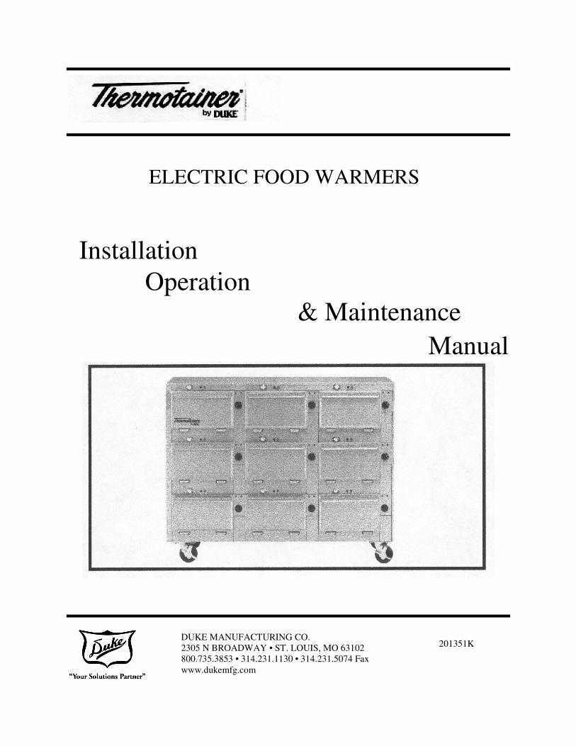
DUKE MANUFACTURING CO. 2305 N BROADWAY • ST. LOUIS, MO 63102 800.735.3853 • 314.231.1130 • 314.231.5074 Fax www.dukemfg.com
201351K
ELECTRIC FOOD WARMERS
Installation Operation
& Maintenance Manual
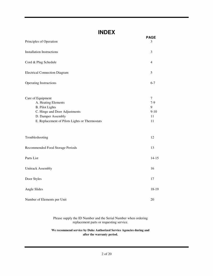
2 of 20
INDEX PAGE
Principles of Operation 3
Installation Instructions 3
Cord & Plug Schedule 4
Electrical Connection Diagram 5
Operating Instructions 6-7
Care of Equipment 7 A. Heating Elements 7-9 B. Pilot Lights 9 C. Hinge and Door Adjustments 9-10 D. Damper Assembly 11 E. Replacement of Pilots Lights or Thermostats 11
Troubleshooting 12
Recommended Food Storage Periods 13
Parts List 14-15
Unitrack Assembly 16
Door Styles 17
Angle Slides 18-19
Number of Elements per Unit 20
Please supply the ID Number and the Serial Number when ordering replacement parts or requesting service.
We recommend service by Duke Authorized Service Agencies during and
after the warranty period.
3 of 20
PRINCIPLES OF OPERATION The Thermotainer has been designed to preserve hot food at its proper temperature in its own moisture, without the addition of water, steam or circulating fans. The hot air surrounding the food compartment is electrically heated and automatically controlled to maintain the desired temperature. Each cabinet has one or more thermostats depending upon its design and model number. Each compartment has a vent or damper for the control of moist or dry foods.
The primary function of a Thermotainer is for the intermediate storage of hot food after it leaves the cooking unit until it is ready to serve. Thermotainers are not designed to reheat food that has cooled, thawing frozen food, or for cooking. These uses are not recommended.
INSTALLATION The Thermotainer, when it leaves the factory, is assembled and ready for Installation. The nameplate on the thermostat side of the cabinet contains model number, serial number, volts, hertz, wattage and instructions on the damper operation. The Thermotainer must be connected to the proper electrical power source as indicated on the nameplate. Failure to do this may cause serious damage, prevent proper operation and void the manufacturer's warranty.
The access to the electrical connection box is normally located at the lower front (thermostat side) bottom. It is covered with an access cover panel that is held in place by two screws. Concealed, but adjacent to the right side of the electrical connection box is a wire chase that runs front to back. It is visible by looking underneath the unit. The wire chase permits access to the side knockout of the electrical connection box and to "stub up" or rear connects the electrical power source. Some Thermotainers may be equipped with cords and plugs or the electrical connection box may be in another location depending upon the design and location that may have been specified. It is not necessary to disassemble any part of the Thermotainer to make the electrical connection. Thermotainers should be moved by carefully lifting underneath and placed in the desired location. They should not be pushed or shoved as this may damage the legs, the hardware, or the electrical components. After setting in place, the Thermotainer must be leveled. If equipped with legs, the adjusting feet should be turned to level the cabinet.
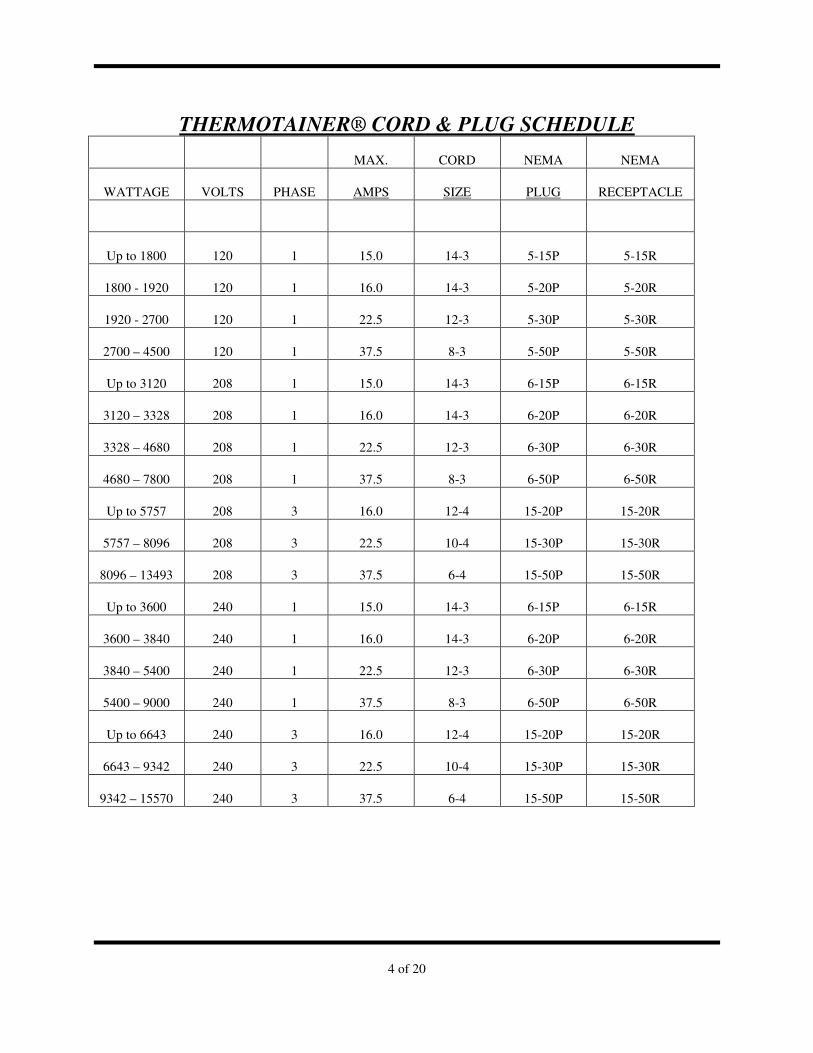
4 of 20
THERMOTAINER® CORD & PLUG SCHEDULE
MAX. CORD NEMA NEMA
WATTAGE VOLTS PHASE AMPS SIZE PLUG RECEPTACLE
Up to 1800 120 1 15.0 14-3 5-15P 5-15R
1800 - 1920 120 1 16.0 14-3 5-20P 5-20R
1920 - 2700 120 1 22.5 12-3 5-30P 5-30R
2700 – 4500 120 1 37.5 8-3 5-50P 5-50R
Up to 3120 208 1 15.0 14-3 6-15P 6-15R
3120 – 3328 208 1 16.0 14-3 6-20P 6-20R
3328 – 4680 208 1 22.5 12-3 6-30P 6-30R
4680 – 7800 208 1 37.5 8-3 6-50P 6-50R
Up to 5757 208 3 16.0 12-4 15-20P 15-20R
5757 – 8096 208 3 22.5 10-4 15-30P 15-30R
8096 – 13493 208 3 37.5 6-4 15-50P 15-50R
Up to 3600 240 1 15.0 14-3 6-15P 6-15R
3600 – 3840 240 1 16.0 14-3 6-20P 6-20R
3840 – 5400 240 1 22.5 12-3 6-30P 6-30R
5400 – 9000 240 1 37.5 8-3 6-50P 6-50R
Up to 6643 240 3 16.0 12-4 15-20P 15-20R
6643 – 9342 240 3 22.5 10-4 15-30P 15-30R
9342 – 15570 240 3 37.5 6-4 15-50P 15-50R
5 of 20
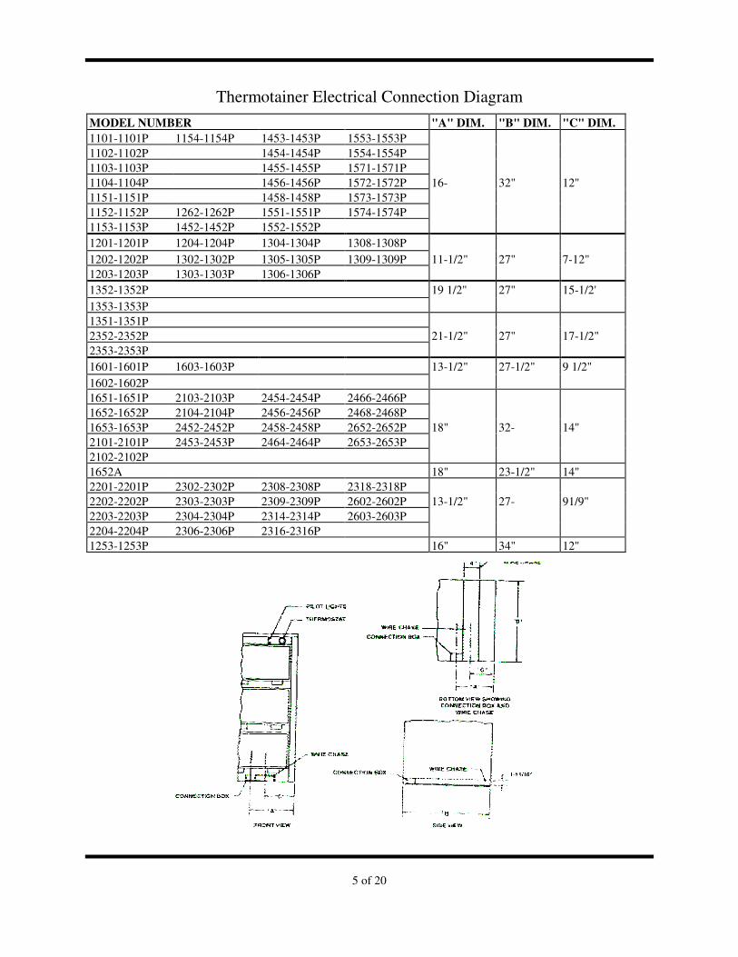
Thermotainer Electrical Connection Diagram
MODEL NUMBER "A" DIM. "B" DIM. "C" DIM.
1101-1101P 1154-1154P 1453-1453P 1553-1553P 1102-1102P 1454-1454P 1554-1554P 1103-1103P 1455-1455P 1571-1571P 1104-1104P 1456-1456P 1572-1572P 16- 32" 12" 1151-1151P 1458-1458P 1573-1573P 1152-1152P 1262-1262P 1551-1551P 1574-1574P 1153-1153P 1452-1452P 1552-1552P
1201-1201P 1204-1204P 1304-1304P 1308-1308P
1202-1202P 1302-1302P 1305-1305P 1309-1309P 11-1/2" 27" 7-12"
1203-1203P 1303-1303P 1306-1306P
1352-1352P 19 1/2" 27" 15-1/2' 1353-1353P 1351-1351P 2352-2352P 21-1/2" 27" 17-1/2" 2353-2353P
1601-1601P 1603-1603P 13-1/2" 27-1/2" 9 1/2" 1602-1602P 1651-1651P 2103-2103P 2454-2454P 2466-2466P 1652-1652P 2104-2104P 2456-2456P 2468-2468P 1653-1653P 2452-2452P 2458-2458P 2652-2652P 18" 32- 14" 2101-2101P 2453-2453P 2464-2464P 2653-2653P 2102-2102P 1652A 18" 23-1/2" 14" 2201-2201P 2302-2302P 2308-2308P 2318-2318P 2202-2202P 2303-2303P 2309-2309P 2602-2602P 13-1/2" 27- 91/9" 2203-2203P 2304-2304P 2314-2314P 2603-2603P 2204-2204P 2306-2306P 2316-2316P 1253-1253P 16" 34" 12"
6 of 20
If legs were not supplied, it may be necessary to shim
under the bottom to level. After leveling, with the
thermostat (s) in the off position, the Thermotainer
can be connected to the electrical power source.
Installation must be in accordance with national or
local electrical and sanitation codes. In order to
remain in compliance with NSF standards, the base
must be sealed to the counter or floor. Use General
Electric RTV-102, Dow Corning 781 Building
Sealant or any silicone based product, which is
approved and acts as an adhesive/ sealant.
When the electrical connection is completed, install
the stainless steel angle slides inside the
compartments. Clean and polish the inside and
outside before preheating for the first time. This will
assure the factory finish remaining bright for years.
See Care of the Equipment section of this manual.
Electrical Control
The temperature is maintained by a thermostat (s)
that can be adjusted to the desired temperature. The
thermostat is directly connected to the heating
elements, which in turn heat the air space
surrounding each compartment. A thermostat may
control one or more compartments depending upon
the design.
Each Thermotainer is carefully inspected and tested
at the factory. The thermostat (s) are adjusted and
calibrated with precision temperature indicating
instruments.
The thermostat dial temperature numbers may not
necessarily indicate the exact compartment
temperature. After it has been determined by use at
which setting food keeps best, the thermostat should
be kept at this setting to maintain this temperature.
Your own experience will be the best guide. Do not
constantly change the thermostat setting once it has
been determined unless the foods being stored require
different temperatures.
NOTE: Thermostats are factory calibrated. Field
calibration of the thermostat is not covered by
warranty. Preheating
To prevent food spoilage and harmful bacteria
growth, food should not be placed in a cold
Thermotainer. Preheat by turning the thermostat knob
to the desired temperature setting. Allow at least 1-
1/2 hours to reach the set temperature.
In heating a cold unit, set the thermostat to the desired
temperature. Do not turn to a higher setting as this
will waste energy, cause the Thermotainer to be
heated above the desired temperature and will not
increase the speed of preheating.
OPERATING INSTRUCTIONS
When the operating temperature has been reached,
the red pilot light will go out. (It cycles on and off as
the temperature varies in the compartment.) The
Thermotainer is now ready to accept food for storage.
If the food is to be served in the same pan in which it
was cooked, it may be left in this pan and placed in
the compartment. Otherwise pan food immediately
after cooking into another utensil and place in the
compartment. The Thermotainer keeps the food in
perfect condition during the interval between cooking
and serving.
All foods should be placed in the compartment while
hot. The use of the Thermotainer for reheating or
warming cold food is not recommended. If the
Thermotainer is to be used for reheating food, consult a
competent food or health authority for information
concerning which foods may be cooled and reheated
safely.
Most foods can be kept in their best condition at a
temperature of approximately 175°F (79.4°C), but the
exact temperature will vary with the kind of food and
the method of preparation. Minor temperature
fluctuations will not affect the quality of most foods.
It is not possible to give exact instructions that will fit
all conditions. It is suggested that you experiment by
increasing or decreasing the temperature until you
find the most suitable temperatures for various types
of foods. For suggested temperature settings, consult
the food storage instruction sheet on page 16.
7 of 20
IMPORTANT HEALTH WARNING: The minimum
FDA/NSF temperature for storing hot food is 140°F
(60°C). Some local health codes require a minimum of
150°F (65.5°C). Consult your local health code or
inspector to determine the minimum safe storage
temperature for your area. Storing hot food below
140°F (60°C) may cause the growth of harmful bacteria,
which can result in food poisoning.
Some "dry" type food, such as breaded meats, fish,
etc., when kept at their proper temperature, require
less moisture in the compartment to prevent
sogginess. For this reason, all compartments are
equipped with vents or dampers. For "dry" type foods
the damper should be open. For "moist" type foods
the damper should be closed. Refer to the damper
operating instructions on the nameplate. Keep the
damper in either full open or full closed position
depending upon the food being stored. With a little
experience, you will soon know the proper position.
Some foods can be kept in good condition much
longer than others can, and certain foods cannot be
satisfactorily stored in any manner. This depends
upon the type of food and method of preparation. Do
not expect the impossible from the Thermotainer. If
used properly and within its design limitations, it will
keep food with less deterioration and for a longer
period of time than is possible with other equipment.
By maintaining the quality between the time the food
is cooked and served, the Thermotainer will assure
food being served in the best possible condition.
CARE OF EQUIPMENT
The exterior and compartments should be cleaned
daily. Turn off the power before cleaning. Avoid
using excessive amounts of water. A damp cloth and
any good grease solvent, commercial detergent, or
soap should remove any food that has spilled. Do not
use harsh scouring powders, steel wool, toxic
chemicals, or abrasive cleansers. Thoroughly rinse
after using cleaning compounds.
NOTE: Never steam clean or hose down with water.
Electric components will fail due to moisture.
If you have been using the compartments with the
damper continually open, at least once a week set the
thermostat at 200°F (94°C) for several hours with the
doors propped open, the dampers open, and the
compartments empty. This will drive off any
excessive moisture, which may have accumulated in
the heater compartment. Remember to turn off the
thermostat and close the doors after you have
completed this operation.
A. Heating Elements
Should the Thermotainer fail to heat or reach the
desired temperature, first check the fuses or circuit
breakers in the electrical power line to the
Thermotainer. If the fuses or circuit breakers are
operating, a qualified electrician, experienced
maintenance personnel, or service agency should do
further inspection. If you are not qualified to perform
service, you may cause damage to the Thermotainer
or injure yourself.
To inspect, service, or replace the heating elements,
see the accompanying diagrams in this manual. To
service, special tools are not necessary. Do not
excessively force or jam any parts as Thermotainers
are designed for field service and disassembly.
If the fuses or circuit breakers are in operating order,
before disassembling to inspect the heating elements,
using a voltmeter, check the electrical connections at
the connection box, also before and after the
thermostat is in its "on" position. This will determine
if current is flowing to and through the thermostat. If
there is no current flow, the thermostat may have
malfunctioned or there may be a break in the wiring
circuit. This requires a replacement of the thermostat
or repair of the wiring circuit, not a heating element
replacement.
If power is flowing through the thermostat, an
alternate check can be made with an ammeter. With
the thermostat in the "on" position, the ammeter
should record amperes approximately equal to the
total wattage divided by the voltage. Example: A
single phase Thermotainer with a 2750 watt rating at
208 volts

8 of 20
TYPICAL DIAGRAMS SHOWING HOW TO REMOVE COMPARTMENT AND DOORS FOR
INSPECTION OR REPLACEMENT OF HEATING ELEMENTS IN THERMOTAINERS
Diagram showing how to remove compartment for inspection or replacement of heating element in Thermotainers.
4. Disconnect wire from heating element terminal.
5. Remove bolt holding heating element. Slide element forward then lift up and out
2. Remove compartment-retaining screws.
3. Slide compartment out.
1. Release tension on hinges and remove door.
Diagram showing how to remove compartment for inspection or replacement of heating element in a pass-thru type Thermotainers.
4. Disconnect wire from heating element terminal.
5. Remove bolt holding heating element. Slide element forward then lift up and out
2. Remove compartment-retaining screws.
3. Slide compartment out.
1. Release tension on hinges and remove door.
2. Remove compartment-retaining screws.
9 of 20
should read about 13.2 ampere. If the reading is much
less or zero, one of more heating elements may need
replacement.
To use this test you must observe the design of the
Thermotainer as to the number of thermostats and
location of the heating elements. Thermotainers with
only one thermostat have all heating elements located
at the bottom of the cabinet in the air space, on either
side and between each bottom compartment.
Thermotainers with multiple thermostats will have
heating elements at various locations depending upon
the model.
B.Pilot Lights
1. When power is connected to the Thermotainer the
amber pilot light will glow continuously. Any
interruption of the power source will extinguish the
light. This may be caused by power, fuse or circuit
breaker failure. The amber pilot light will continue to
glow after the thermostat and heating elements shut
off and the Thermotainer is not in use. The cost of
pilot light operation is negligible. Make no attempt to
remove or shut it off — it is an added protection.
2. The red pilot light will glow when the thermostat is
turned on and will go off and on as the thermostat
cycles to maintain the temperature setting selected.
When the red pilot light does not glow after cycling,
the Thermotainer is at the set temperature.
3. Removal and replacement of pilot lights and
thermostats are covered in the Thermostat
Recalibration Instruction section of this manual.
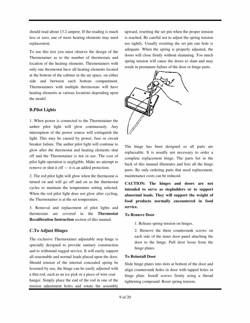
C.To Adjust Hinges
The exclusive Thermotainer adjustable stop hinge is
specially designed to provide sanitary construction
and to withstand rugged service. It will easily support
all reasonable and normal loads placed upon the door.
Should tension of the internal concealed spring be
lessened by use, the hinge can be easily adjusted with
a thin rod, such as an ice pick or a piece of wire coat
hanger. Simply place the end of the rod in one of the
tension adjustment holes and rotate the assembly
upward, resetting the set pin when the proper tension
is reached. Be careful not to adjust the spring tension
too tightly. Usually resetting the set pin one hole is
adequate. When the spring is properly adjusted, the
doors will close firmly without slamming. Too much
spring tension will cause the doors to slam and may
result in premature failure of the door or hinge parts.
The hinge has been designed so all parts are
replaceable. It is usually not necessary to order a
complete replacement hinge. The parts list in the
back of this manual illustrates and lists all the hinge
parts. By only ordering parts that need replacement,
maintenance costs can be reduced.
CAUTION: The hinges and doors are not
intended to serve as stepladders or to support
abnormal loads. They will support the weight of
food products normally encountered in food
service.
To Remove Door
1. Release spring tension on hinges.
2. Remove the three countersunk screws on
each side of the inner door panel attaching the
door to the hinge. Pull door loose from the
hinge plates.
To Reinstall Door
Slide hinge plates into slots at bottom of the door and
align countersunk holes in door with tapped holes in
hinge plate. Install screws firmly using a thread
tightening compound. Reset spring tension.
10 of 20
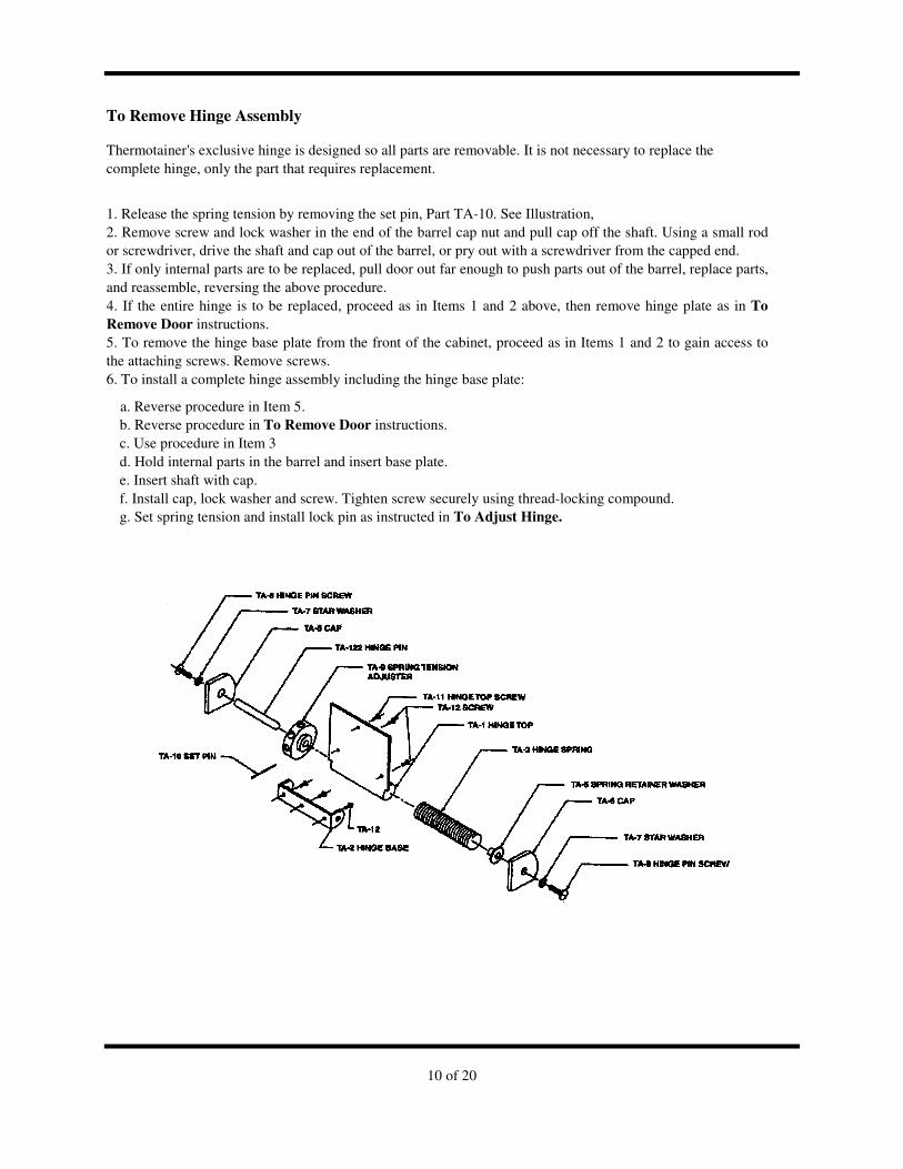
To Remove Hinge Assembly Thermotainer's exclusive hinge is designed so all parts are removable. It is not necessary to replace the complete hinge, only the part that requires replacement.
1. Release the spring tension by removing the set pin, Part TA-10. See Illustration, 2. Remove screw and lock washer in the end of the barrel cap nut and pull cap off the shaft. Using a small rod or screwdriver, drive the shaft and cap out of the barrel, or pry out with a screwdriver from the capped end. 3. If only internal parts are to be replaced, pull door out far enough to push parts out of the barrel, replace parts, and reassemble, reversing the above procedure. 4. If the entire hinge is to be replaced, proceed as in Items 1 and 2 above, then remove hinge plate as in To
Remove Door instructions. 5. To remove the hinge base plate from the front of the cabinet, proceed as in Items 1 and 2 to gain access to the attaching screws. Remove screws. 6. To install a complete hinge assembly including the hinge base plate:
a. Reverse procedure in Item 5. b. Reverse procedure in To Remove Door instructions. c. Use procedure in Item 3 d. Hold internal parts in the barrel and insert base plate. e. Insert shaft with cap. f. Install cap, lock washer and screw. Tighten screw securely using thread-locking compound. g. Set spring tension and install lock pin as instructed in To Adjust Hinge.
11 of 20
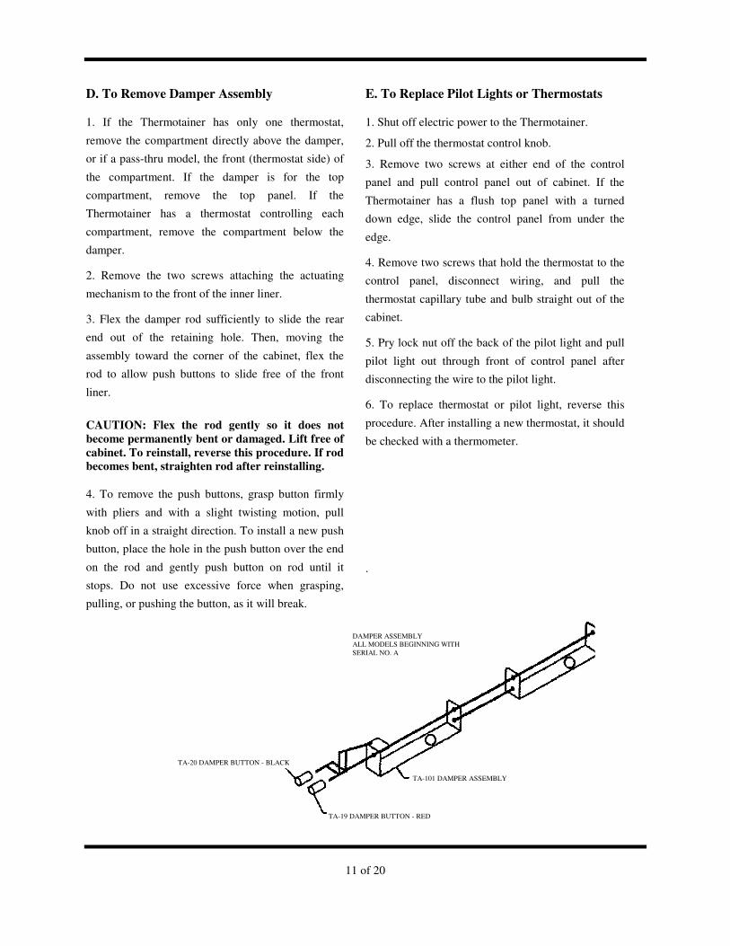
D. To Remove Damper Assembly
1. If the Thermotainer has only one thermostat,
remove the compartment directly above the damper,
or if a pass-thru model, the front (thermostat side) of
the compartment. If the damper is for the top
compartment, remove the top panel. If the
Thermotainer has a thermostat controlling each
compartment, remove the compartment below the
damper.
2. Remove the two screws attaching the actuating
mechanism to the front of the inner liner.
3. Flex the damper rod sufficiently to slide the rear
end out of the retaining hole. Then, moving the
assembly toward the corner of the cabinet, flex the
rod to allow push buttons to slide free of the front
liner.
CAUTION: Flex the rod gently so it does not
become permanently bent or damaged. Lift free of
cabinet. To reinstall, reverse this procedure. If rod
becomes bent, straighten rod after reinstalling.
4. To remove the push buttons, grasp button firmly
with pliers and with a slight twisting motion, pull
knob off in a straight direction. To install a new push
button, place the hole in the push button over the end
on the rod and gently push button on rod until it
stops. Do not use excessive force when grasping,
pulling, or pushing the button, as it will break.
E. To Replace Pilot Lights or Thermostats
1. Shut off electric power to the Thermotainer.
2. Pull off the thermostat control knob.
3. Remove two screws at either end of the control
panel and pull control panel out of cabinet. If the
Thermotainer has a flush top panel with a turned
down edge, slide the control panel from under the
edge.
4. Remove two screws that hold the thermostat to the
control panel, disconnect wiring, and pull the
thermostat capillary tube and bulb straight out of the
cabinet.
5. Pry lock nut off the back of the pilot light and pull
pilot light out through front of control panel after
disconnecting the wire to the pilot light.
6. To replace thermostat or pilot light, reverse this
procedure. After installing a new thermostat, it should
be checked with a thermometer.
.
LACKTA-20 DAMPER BUTTON - BLACK
DAMPER ASSEMBLY ALL MODELS BEGINNING WITH SERIAL NO. A
TA-101 DAMPER ASSEMBLY
TA-19 DAMPER BUTTON - RED
12 of 20
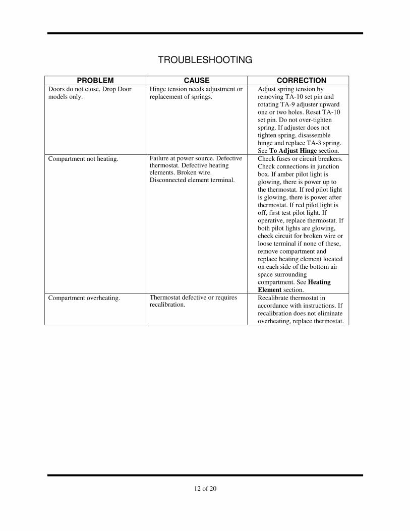
TROUBLESHOOTING
PROBLEM CAUSE CORRECTION Doors do not close. Drop Door models only.
Hinge tension needs adjustment or replacement of springs.
Adjust spring tension by removing TA-10 set pin and rotating TA-9 adjuster upward one or two holes. Reset TA-10 set pin. Do not over-tighten spring. If adjuster does not tighten spring, disassemble hinge and replace TA-3 spring. See To Adjust Hinge section.
Compartment not heating. Failure at power source. Defective thermostat. Defective heating elements. Broken wire. Disconnected element terminal.
Check fuses or circuit breakers. Check connections in junction box. If amber pilot light is glowing, there is power up to the thermostat. If red pilot light is glowing, there is power after thermostat. If red pilot light is off, first test pilot light. If operative, replace thermostat. If both pilot lights are glowing, check circuit for broken wire or loose terminal if none of these, remove compartment and replace heating element located on each side of the bottom air space surrounding compartment. See Heating
Element section. Compartment overheating. Thermostat defective or requires
recalibration. Recalibrate thermostat in accordance with instructions. If recalibration does not eliminate overheating, replace thermostat.
13 of 20
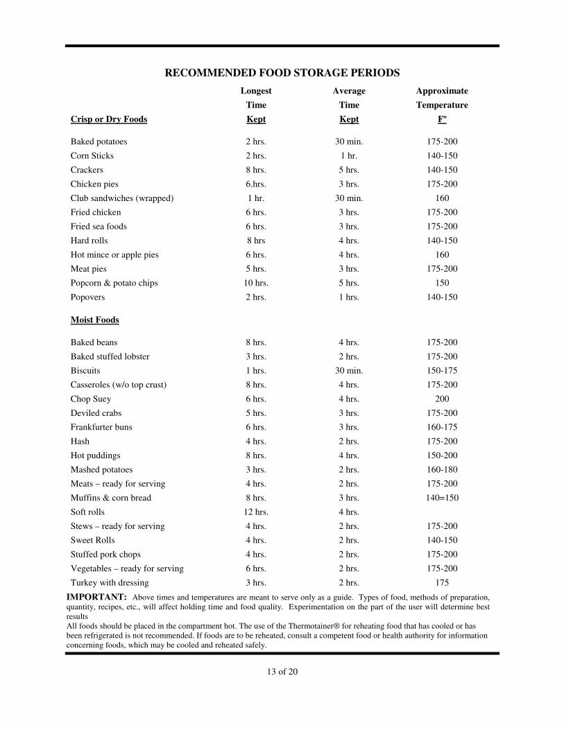
RECOMMENDED FOOD STORAGE PERIODS
Longest Average Approximate
Time Time Temperature
Crisp or Dry Foods Kept Kept Fº
Baked potatoes 2 hrs. 30 min. 175-200
Corn Sticks 2 hrs. 1 hr. 140-150
Crackers 8 hrs. 5 hrs. 140-150
Chicken pies 6.hrs. 3 hrs. 175-200
Club sandwiches (wrapped) 1 hr. 30 min. 160
Fried chicken 6 hrs. 3 hrs. 175-200
Fried sea foods 6 hrs. 3 hrs. 175-200
Hard rolls 8 hrs 4 hrs. 140-150
Hot mince or apple pies 6 hrs. 4 hrs. 160
Meat pies 5 hrs. 3 hrs. 175-200
Popcorn & potato chips 10 hrs. 5 hrs. 150
Popovers 2 hrs. 1 hrs. 140-150
Moist Foods
Baked beans 8 hrs. 4 hrs. 175-200
Baked stuffed lobster 3 hrs. 2 hrs. 175-200
Biscuits 1 hrs. 30 min. 150-175
Casseroles (w/o top crust) 8 hrs. 4 hrs. 175-200
Chop Suey 6 hrs. 4 hrs. 200
Deviled crabs 5 hrs. 3 hrs. 175-200
Frankfurter buns 6 hrs. 3 hrs. 160-175
Hash 4 hrs. 2 hrs. 175-200
Hot puddings 8 hrs. 4 hrs. 150-200
Mashed potatoes 3 hrs. 2 hrs. 160-180
Meats – ready for serving 4 hrs. 2 hrs. 175-200
Muffins & corn bread 8 hrs. 3 hrs. 140=150
Soft rolls 12 hrs. 4 hrs.
Stews – ready for serving 4 hrs. 2 hrs. 175-200
Sweet Rolls 4 hrs. 2 hrs. 140-150
Stuffed pork chops 4 hrs. 2 hrs. 175-200
Vegetables – ready for serving 6 hrs. 2 hrs. 175-200
Turkey with dressing 3 hrs. 2 hrs. 175
IMPORTANT: Above times and temperatures are meant to serve only as a guide. Types of food, methods of preparation, quantity, recipes, etc., will affect holding time and food quality. Experimentation on the part of the user will determine best results All foods should be placed in the compartment hot. The use of the Thermotainer® for reheating food that has cooled or has been refrigerated is not recommended. If foods are to be reheated, consult a competent food or health authority for information concerning foods, which may be cooled and reheated safely.
14 of 20
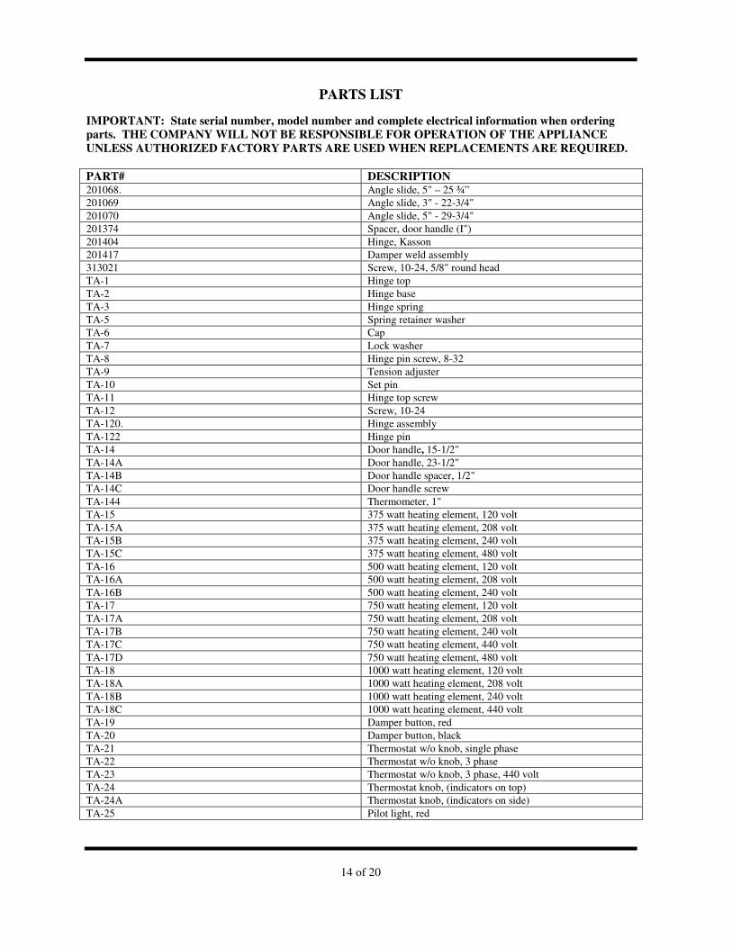
PARTS LIST
IMPORTANT: State serial number, model number and complete electrical information when ordering
parts. THE COMPANY WILL NOT BE RESPONSIBLE FOR OPERATION OF THE APPLIANCE
UNLESS AUTHORIZED FACTORY PARTS ARE USED WHEN REPLACEMENTS ARE REQUIRED.
PART# DESCRIPTION 201068. Angle slide, 5" – 25 ¾” 201069 Angle slide, 3" - 22-3/4" 201070 Angle slide, 5" - 29-3/4" 201374 Spacer, door handle (I") 201404 Hinge, Kasson 201417 Damper weld assembly 313021 Screw, 10-24, 5/8" round head TA-1 Hinge top TA-2 Hinge base TA-3 Hinge spring TA-5 Spring retainer washer TA-6 Cap TA-7 Lock washer TA-8 Hinge pin screw, 8-32 TA-9 Tension adjuster TA-10 Set pin TA-11 Hinge top screw TA-12 Screw, 10-24 TA-120. Hinge assembly TA-122 Hinge pin TA-14 Door handle, 15-1/2" TA-14A Door handle, 23-1/2" TA-14B Door handle spacer, 1/2" TA-14C Door handle screw TA-144 Thermometer, 1" TA-15 375 watt heating element, 120 volt TA-15A 375 watt heating element, 208 volt TA-15B 375 watt heating element, 240 volt TA-15C 375 watt heating element, 480 volt TA-16 500 watt heating element, 120 volt TA-16A 500 watt heating element, 208 volt TA-16B 500 watt heating element, 240 volt TA-17 750 watt heating element, 120 volt TA-17A 750 watt heating element, 208 volt TA-17B 750 watt heating element, 240 volt TA-17C 750 watt heating element, 440 volt TA-17D 750 watt heating element, 480 volt TA-18 1000 watt heating element, 120 volt TA-18A 1000 watt heating element, 208 volt TA-18B 1000 watt heating element, 240 volt TA-18C 1000 watt heating element, 440 volt TA-19 Damper button, red TA-20 Damper button, black TA-21 Thermostat w/o knob, single phase TA-22 Thermostat w/o knob, 3 phase TA-23 Thermostat w/o knob, 3 phase, 440 volt TA-24 Thermostat knob, (indicators on top) TA-24A Thermostat knob, (indicators on side) TA-25 Pilot light, red

15 of 20
PARTS LIST FOR ALL MODELS BEGINNING WITH SERIAL NUMBER TA-26 Pilot light, amber TA-31 5” caster, stationary TA-315 Leg, S/S TA-32 5" caster, swivel with brake TA-320 Thumbscrew, 8-32 TA-327 Support stud, pan rail TA-348 Screw, 6-32, ¾” TA-36A Uni-dor roller TA36B Úni-dor stop TA-36HA Uni-dor arm assembly, 2 each arm TA-36J Uni-dor arm link TA-36A Uni-dor- spring TA-36L Stainless steel cotter pin TA-36M Stainless steel castellated nut TA-37 Door, “C” style, 10-1/4” – 16-7/8” TA-38 Door, “J” style, 10-1/4” – 24-7/8” TA-39 Door, "E" style, 10-1/4" - 31-7/8" TA-40 Door, "BB3" style, 12-13/32" - 18", Right TA-41 Door, "BB3" style, 12-13/32" - 18", Left TA-42 Door, "UB" style, 12-13/32" - 22-1/4", Right TA-43 Door, "UB" style, 12-13/32" - 22-1/4", Left TA-44 Door, "BB" style, 12-13/32" - 28-1/4", Right TA-45 Door, "BB" style, 12-13/32" - 28-1/4", Left TA-999A 1253 door seal, 16-1/8" TA-999B 1252 door seal, 26-3/8" TA-999C 1151 door seal, 20-3/8
16 of 20
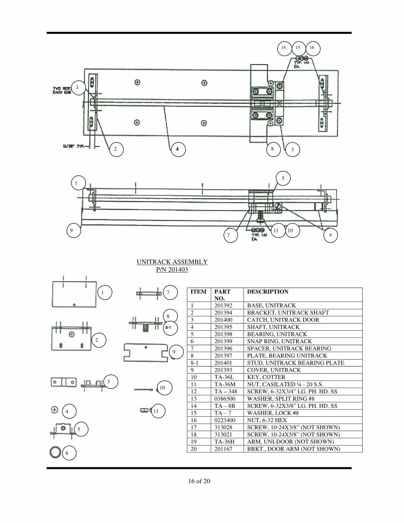
ITEM PART
NO.
DESCRIPTION
1 201392 BASE, UNITRACK 2 201394 BRACKET, UNITRACK SHAFT 3 201400 CATCH, UNITRACK DOOR 4 201395 SHAFT, UNITRACK 5 201398 BEARING, UNITRACK 6 201399 SNAP RING, UNITRACK 7 201396 SPACER, UNITRACK BEARING 8 201397 PLATE, BEARING UNITRACK 8-1 201401 STUD, UNITRACK BEARING PLATE 9 201393 COVER, UNITRACK 10 TA-36L KEY, COTTER 11 TA-36M NUT, CASILATED ¼ - 20 S.S. 12 TA – 348 SCREW, 6-32X3/4” LG. PH. HD. SS 13 0386500 WASHER, SPLIT RING #8 14 TA – 8B SCREW, 6-32X3/8” LG. PH. HD. SS 15 TA – 7 WASHER, LOCK #8 16 0223400 NUT, 6-32 HEX 17 313028 SCREW, 10-24X3/8” (NOT SHOWN) 18 313021 SCREW, 10-24X5/8” (NOT SHOWN) 19 TA-36H ARM, UNI-DOOR (NOT SHOWN) 20 201167 BRKT., DOOR ARM (NOT SHOWN)
2 4 3
1
9 7
10 6
1
2
8
1
14 15 16
5
11
3
4
5
6
7
8
9
10
11
8-1
UNITRACK ASSEMBLY P/N 201403
17 of 20
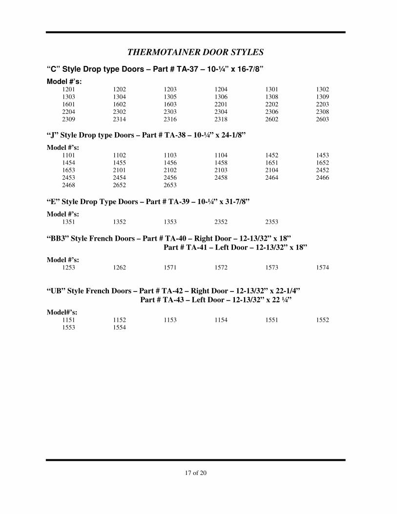
THERMOTAINER DOOR STYLES
“C” Style Drop type Doors – Part # TA-37 – 10-¼” x 16-7/8”
Model #’s: 1201 1202 1203 1204 1301 1302 1303 1304 1305 1306 1308 1309 1601 1602 1603 2201 2202 2203 2204 2302 2303 2304 2306 2308 2309 2314 2316 2318 2602 2603
“J” Style Drop type Doors – Part # TA-38 – 10-¼” x 24-1/8”
Model #’s: 1101 1102 1103 1104 1452 1453 1454 1455 1456 1458 1651 1652 1653 2101 2102 2103 2104 2452 2453 2454 2456 2458 2464 2466 2468 2652 2653
“E” Style Drop Type Doors – Part # TA-39 – 10-¼” x 31-7/8”
Model #’s: 1351 1352 1353 2352 2353
“BB3” Style French Doors – Part # TA-40 – Right Door – 12-13/32” x 18”
Part # TA-41 – Left Door – 12-13/32” x 18”
Model #’s: 1253 1262 1571 1572 1573 1574
“UB” Style French Doors – Part # TA-42 – Right Door – 12-13/32” x 22-1/4”
Part # TA-43 – Left Door – 12-13/32” x 22 ¼”
Model#’s: 1151 1152 1153 1154 1551 1552 1553 1554
18 of 20
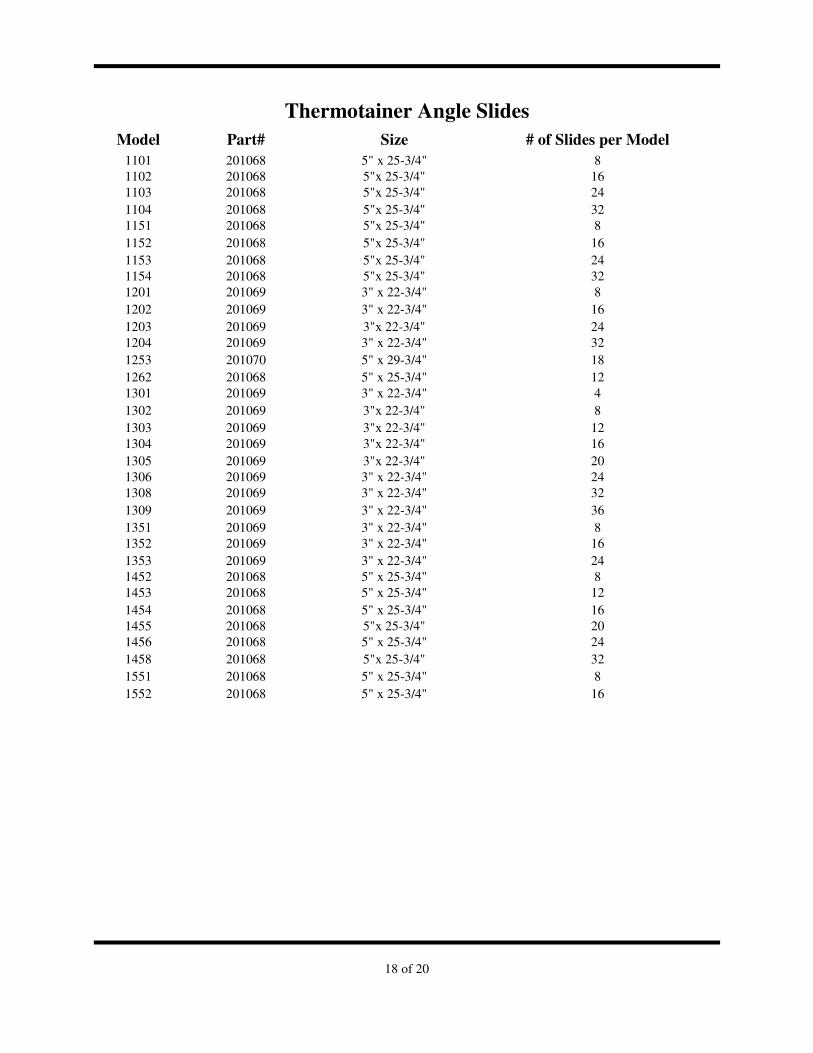
Thermotainer Angle Slides
Model Part# Size # of Slides per Model
1101 201068 5" x 25-3/4" 8 1102 201068 5"x 25-3/4" 16 1103 201068 5"x 25-3/4" 24 1104 201068 5"x 25-3/4" 32 1151 201068 5"x 25-3/4" 8 1152 201068 5"x 25-3/4" 16 1153 201068 5"x 25-3/4" 24 1154 201068 5"x 25-3/4" 32 1201 201069 3" x 22-3/4" 8 1202 201069 3" x 22-3/4" 16 1203 201069 3"x 22-3/4" 24 1204 201069 3" x 22-3/4" 32 1253 201070 5" x 29-3/4" 18 1262 201068 5" x 25-3/4" 12 1301 201069 3" x 22-3/4" 4 1302 201069 3"x 22-3/4" 8 1303 201069 3"x 22-3/4" 12 1304 201069 3"x 22-3/4" 16 1305 201069 3"x 22-3/4" 20 1306 201069 3" x 22-3/4" 24 1308 201069 3" x 22-3/4" 32 1309 201069 3" x 22-3/4" 36 1351 201069 3" x 22-3/4" 8 1352 201069 3" x 22-3/4" 16 1353 201069 3" x 22-3/4" 24 1452 201068 5" x 25-3/4" 8 1453 201068 5" x 25-3/4" 12 1454 201068 5" x 25-3/4" 16 1455 201068 5"x 25-3/4" 20 1456 201068 5" x 25-3/4" 24 1458 201068 5"x 25-3/4" 32 1551 201068 5" x 25-3/4" 8 1552 201068 5" x 25-3/4" 16
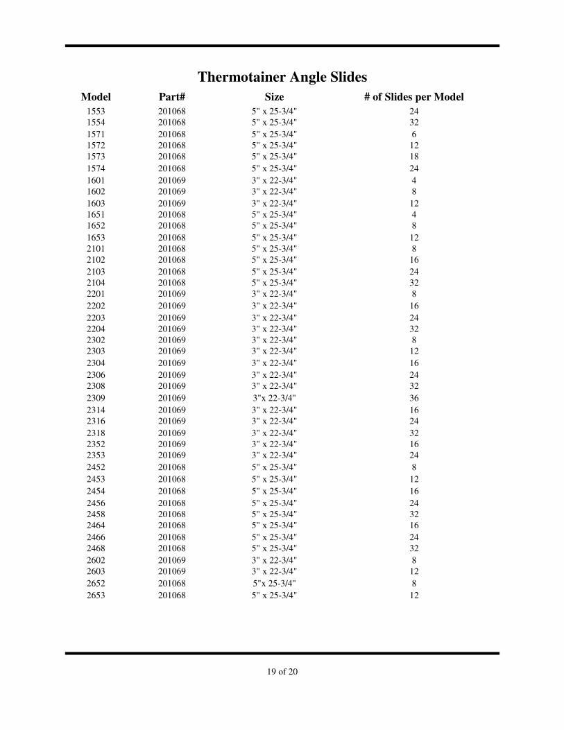
19 of 20
Thermotainer Angle Slides
Model Part# Size # of Slides per Model
1553 201068 5" x 25-3/4" 24 1554 201068 5" x 25-3/4" 32 1571 201068 5" x 25-3/4" 6 1572 201068 5" x 25-3/4" 12 1573 201068 5" x 25-3/4" 18 1574 201068 5" x 25-3/4" 24 1601 201069 3" x 22-3/4" 4 1602 201069 3" x 22-3/4" 8 1603 201069 3" x 22-3/4" 12 1651 201068 5" x 25-3/4" 4 1652 201068 5" x 25-3/4" 8 1653 201068 5" x 25-3/4" 12 2101 201068 5" x 25-3/4" 8 2102 201068 5" x 25-3/4" 16 2103 201068 5" x 25-3/4" 24 2104 201068 5" x 25-3/4" 32 2201 201069 3" x 22-3/4" 8 2202 201069 3" x 22-3/4" 16 2203 201069 3" x 22-3/4" 24 2204 201069 3" x 22-3/4" 32 2302 201069 3" x 22-3/4" 8 2303 201069 3" x 22-3/4" 12 2304 201069 3" x 22-3/4" 16 2306 201069 3" x 22-3/4" 24 2308 201069 3" x 22-3/4" 32 2309 201069 3"x 22-3/4" 36 2314 201069 3" x 22-3/4" 16 2316 201069 3" x 22-3/4" 24 2318 201069 3" x 22-3/4" 32 2352 201069 3" x 22-3/4" 16 2353 201069 3" x 22-3/4" 24 2452 201068 5" x 25-3/4" 8 2453 201068 5" x 25-3/4" 12 2454 201068 5" x 25-3/4" 16 2456 201068 5" x 25-3/4" 24 2458 201068 5" x 25-3/4" 32 2464 201068 5" x 25-3/4" 16 2466 201068 5" x 25-3/4" 24 2468 201068 5" x 25-3/4" 32 2602 201069 3" x 22-3/4" 8 2603 201069 3" x 22-3/4" 12 2652 201068 5"x 25-3/4" 8 2653 201068 5" x 25-3/4" 12
20 of 20
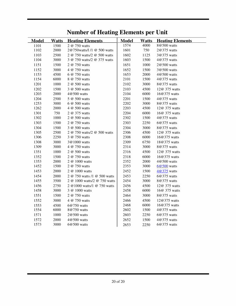
Number of Heating Elements per Unit
Model Watts Heating Elements Model Watts Heating Elements 1101 1500 2 @ 750 watts 1574 4000 8@500 watts 1102 2000 2@750watts/l /1 @ 500 watts 1601 750 2@375 watts 1103 2500 2 @ 750 watts/2 @ 500 watts 1602 1125 3@375 watts 1104 3000 3 @ 750 watts/2 @ 375 watts 1603 1500 4@375 watts 1151 1500 2 @ 750 watts 1651 1000 2@500 watts 1152 3000 4 @ 750 watts 1652 1500 3@500 watts 1153 4500 6 @ 750 watts 1653 2000 4@500 watts 1154 6000 8 @ 750 watts 2101 1500 4@375 watts 1201 1000 2 @ 500 watts 2102 3000 8@375 watts 1202 1500 3 @ 500 watts 2103 4500 12@ 375 watts 1203 2000 4@500 watts 2104 6000 16@375 watts 1204 2500 5 @ 500 watts 2201 1500 4@375 watts 1253 3000 6 @ 500 watts 2202 3000 8@375 watts 1262 2000 4 @ 500 watts 2203 4500 12@ 375 watts 1301 750 2 @ 375 watts 2204 6000 16@ 375 watts 1302 1000 2 @ 500 watts 2302 1500 4@375 watts 1303 1500 2 @ 750 watts 2303 2250 6@375 watts 1304 1500 3 @ 500 watts 2304 3000 8@375 watts 1305 2500 2 @ 750 watts/2 @ 500 watts 2306 4500 12@ 375 watts 1306 2250 3 @ 750 watts 2308 6000 16@375 watts 1308 3000 3@1000 watts 2309 6750 18@375 watts 1309 3000 4 @ 750 watts 2314 3000 8@375 watts 1351 1000 2 @ 500 watts 2316 4500 12@ 375 watts 1352 1500 2 @ 750 watts 2318 6000 16@375 watts 1353 2000 2 @ 1000 watts 2352 2000 4@500 watts 1452 1500 2 @ 750 watts 2353 3000 6@500 watts 1453 2000 2 @ 1000 watts 2452 1500 4@375 watts 1454 2000 2 @ 750 watts /1 @ 500 watts 2453 2250 6@375 watts 1455 3500 2 @ 1000 watts/2 @ 750 watts 2454 3000 8@375 watts 1456 2750 2 @1000 watts/1 @ 750 watts 2456 4500 12@ 375 watts 1458 3000 3 @ 1000 watts 2458 6000 16@ 375 watts 1551 1500 2 @ 750 watts 2464 3000 8@375 watts 1552 3000 4 @ 750 watts 2466 4500 12@375 watts 1553 4500 6@750 watts 2468 6000 16@375 watts 1554 6000 8@750 watts 2602 1500 4@375 watts 1571 1000 2@500 watts 2603 2250 6@375 watts 1572 2000 4@500 watts 2652 1500 4@375 watts 1573 3000 6@500 watts 2653 2250 6@375 watts


![SERVICE MANUAL 12VDC WALL THERMOSTAT AIR …1].pdf · 2006-06-16 · Page -5-THERMOSTAT LOCATION Thermostats are very sensitive instruments. For accurate temperature control and comfort](https://static.fdocuments.in/doc/165x107/5e3843dcbe5c8d470f3f409f/service-manual-12vdc-wall-thermostat-air-1pdf-2006-06-16-page-5-thermostat.jpg)


