Installation, Operation & Maintenance Manual …...Installation, Operation & Maintenance Manual...
14
Installation, Operation & Maintenance Manual Submersible Non-Clog Sewage Pumps 4BSE-HLDS 7.5, 11.3, 15 HP @ 1750 RPM IMPORTANT! - Read all instructions in this manual before operating or servicing a pump. barmesapumps.com
Transcript of Installation, Operation & Maintenance Manual …...Installation, Operation & Maintenance Manual...
Installation, Operation &Maintenance ManualSubmersible Non-Clog
Sewage Pumps
4BSE-HLDS7.5, 11.3, 15 HP@ 1750 RPM
IMPORTANT! - Read all instructions in this manual before operating or servicing a pump.
barmesapumps.com

Before installation, read the following instructions carefully. Failure to follow instruction and safety information could cause serious bodily injury, death and/or property damage. Each Barmesa product is carefully inspected to insure proper performance. Closely following these instructions will eliminate potential operating problems, assuring years of trouble-free service.
01
General Safety Information
IMPORTANT! - Barmesa Pumps is not responsible for losses, injury or death resulting from failure to observe these safety precautions, misuse, abuse or misapplication of pumps or equipment.
Installation, wiring, and j u n c t i o n co n n e c t i o n s m u s t b e i n accordance with the National Electric Code and all applicable state and local codes. Requirements may vary depending on usage and location.
WARNING
I n s t a l l a t i o n a n d servicing is to be conducted by qualified personnel only.
WARNING
D o n o t u s e t h e s e pumps in water over 104º F. Do not exceed manufacturers recommended maximum performance, as this could cause the motor to overheat.
WARNING
Ground Fault Circuit Interrupter (GFCI) to be used with plug-in type power cord.
WARNING
A L L R E T U R N E D P R O D U C T S M U S T B E CLEANED, SANITIZED, OR
D E CO N TA M I N AT E D P R I O R TO SHIPMENT, TO INSURE EMPLOYEES WILL NOT BE EXPOSED TO HEALTH HAZARDS IN HANDLING SAID MATERIAL. ALL APPLICABLE LAWS AND REGULATIONS SHALL APPLY.
Keep clear of suction and discharge openings. Do not insert fingers in pump with
power connected; the rotating cutter and/or impeller can cause serious injury.
Always wear eye protection when working on pumps. Do not wear loose clothing that
may become entangled in moving parts.
Pumps build up heat and pressure during operation. Allow time f o r p u m p s t o c o o l
DANGER
before handling or servicing the p u m p o r a n y a c c e s s o r y i t e m s associated with or near the pump.
T h i s p u m p i s n o t i n t e n d e d f o r u s e i n swimming pools or water installations where there is
DANGER
human contact with pumped fluid.
Risk of electric shock. To reduce risk of electric shock, always disconnect pump from power source before
DANGER
handling any aspect of the pumping system. Lock out power and tag.
Do not lift, carry or hang pump by the electrical c a b l e s . D a m a g e t o t h e electrical cables can cause
DANGER
shock, burns or death. Never handle connected power cords with wet hands. Use appropriate lifting device.
S u m p a n d s e w a g e pumps often handle materials which could cause illness or disease. Wear adequate protective clothing when working on a used pump or piping. Never enter a basin after it has been used.
WARNING
Failure to permanently ground the pump, motor and controls before connecting to power can cause shock,
DANGER
burns or death.
These pumps are not to be installed in locations classified as hazardous in accordance with the National
Electric Code, ANSI/NFPA 70.
DANGER
The Uniform Plumbing Code (UPC ) states that sewage systems shall have an audio and visual alarm that signals a malfunction of the systems, that are required to reduce the potencial for property damage.
WARNING
1 Phase ModelsAmps: Volts:
3 Phase ModelsAmps L1-2: Volts L1-2:
Amps L2-3: Volts L2-3:
Amps L3-1: Volts L3-1:
Model Number: _____________________
Serial: ____________
PHASE: ______ HP: __________________
IMPORTANT! - Prior to installation, record Model Number, Serial, Amps, Voltage, Phase and HP from pump name plate for the future reference. Also record the Voltage and Current Readings at Startup:
WARNING
"Danger" indicates an imminently hazardous situation which, if not avoided, WILL result in death or serious injury.
"Warning" indicates an imminenty hazardous situation which, if not avoided, MAY result in death or serious injury.
"Caution" indicates a potentially hazardous situation which, if not avoided, MAY result in minor or moderate injury.
DANGER
CAUTION
barmesapumps.com

DISCHARGE: SPHERICAL SLD HNDLG: LIQUID TEMPERATURE: VOLUTE: MOTOR HOUSING: SEAL PLATE: IMPELLER: SHAFT: SQUARE RINGS: PAINT: SEAL:
DIAPHRAGM: HARDWARE: CORD ENTRY:
UPPER BEARING: LOWER BEARING: MOTOR:
4", 125lb, flange horizontal.3"104° F (40° C) max.Cast iron ASTM A-48 class 30.Cast iron ASTM A-48 class 30.Cast iron ASTM A-48 class 30.2 vane, closed, with vanes on back side. Cast iron ASTM A-48 class 30.416 series stainless steel.Buna-N.Air dry enamel, water based.Double mechanical, oil filled chamber. Silicon carbide outboard, carbon ceramic inboard seal, with stainless steel hardware.Buna-N.300 series stainless steel.40 ft of cord, epoxy sealed housing with secondary pressure grommet for sealing and strain relief.Ball, single row, oil lubricated, for radial load.Ball, single row, oil lubricated, for radial and thrust load.Three phase, NEMA B, oil filled. Requires overload protection to be included in control panel. Class F insulation.
MOISTURE SENSOR: Normally open (N/O) included, requires relay in control panel.TEMPERATURE SENSOR: Normally closed (N/C) included, requires relay in control panel.OPTIONAL EQUIPMENT: Additional cord, tungsten carbide seal, slide rail coupling (SRC-4).
The moisture cord and/or temperature cord is size 18/5, type SO, Ø0.485", for all models.
MODEL HP VOLTS PHASE RPM(Nominal)
MAXAMPS
LOCKEDROTOR AMPS
NEMACODE
CORDSIZE
CORDTYPE
CORDO. D.
WEIGHT(pounds)
4BSE753HLDS 7.5 230 3 1750 26.8 80 D 10/4 SO 0.75" 309
4BSE754HLDS 7.5 460 3 1750 13.4 40 D 10/4 SO 0.75" 309
4BSE1133HLDS 11.3 230 3 1750 28 126 D 10/4 SO 0.75" 340
4BSE1134HLDS 11.3 460 3 1750 14 63 D 10/4 SO 0.75" 340
4BSE1503HLDS 15 230 3 1750 38 160 D 10/4 SO 0.75" 400
4BSE1504HLDS 15 460 3 1750 19 80 D 10/4 SO 0.75" 400
02
Specifications & Dimensions
barmesapumps.com
19"19"19"
14.5"14.5"14.5"
11.75"11.75"11.75"
7.88"7.88"7.88"
5.5"5.5"5.5"
34.12"34.12"34.12"

03
Recommendations and Warnings
Receiving inspectionUpon receiving the pump, it should be inspected for damage or shortages. If damage has occurred, file a claim immediately with the company that delivered the pump. If the manual is removed from the packaging, do not lose or misplace.
StorageAny product that is stored for a period longer than six (6) months from the date of purchase should be bench tested prior to installation. A bench test consists of, checking the impeller to assure it is free turning and a run test to assure the motor (and switch if provided) operate properly.
ControlsManual models require a separate approved pump control device or panel for automatic operation. Be sure the electrical specification of the control selected properly match the electrical specifications of the pump.
SubmergenceThe pump should always be operated in the submerged condition. The minimum sump liquid level should never be less than above the pump’s volute (See Figure 1).
InstallationThese pumps are recommended for use in a sump, basin or lift station. The sump, basin or lift station shall be sealed and vented in accordance with local plumbing codes. This pump is designed to pump sewage, effluent or wastewater, non-explosive and non-corrosive liquids and shall NOT be installed in locations classified as hazardous in accordance with the National Electrical Code (NEC) ANSI/NFPA 70 or Canadian Electric Code (CEC). The pump should never be installed in a trench, ditch, or hole with a dirt bottom. The legs will sink into the dirt and the suction will become plugged.
The installation should be at a sufficient depth to ensure that all plumbing is below the frost line. If this is not feasible, remove the check valve and size the basin to accommodate the additional backflow volume.
Pumps are most commonly installed in simplex or duplex stations or basins with a slide rail system (Barmesa SRC), which allows the pump(s) to be installed or removed without requiring personnel to enter the station, or resting on the basin floor.
Discharge PipingDischarge piping should be as short as possible and sized no smaller than the pump discharge. Do not reduce the discharge pipe size below that which is provided on the pump. Both a check valve and a shut-off valve are recommended for each pump. The check valve is used to prevent backflow into the sump. The shut-off valve is used to manually stop system low during pump servicing.
Liquid Level ControlsThe level control(s) should be mounted on the discharge piping, a cable rack or float pole. The level control should have adequate clearance so it cannot hang up in it’s swing and that the pump is completely submerged when the level control is in the "Off " mode. By adjusting the cord tether the control level can be changed. One cycle of operation should be observed, so that any potential problems can be corrected.
Electrical ConnectionsPower cable:The power cable mounted to the pump must not be modified in any way except for shortening to a specific application. Any splice between the pump and the control panel must be made in accordance with the electric codes. It is recommended that a junction box, if used, be mounted outside the sump or be of at a minimum Nema 4 construction if located within the wet well. DO NOT USE THE POWER CABLE TO LIFT PUMP.
It is recommended that the level control float should be set to insure that the liquid in the sump never drops below the top of the motor housing or a minimum level of 10 inches above the basin floor.
Always rely upon a Certified Electrician for installation.
barmesapumps.com
Bottom of Feet
10"
RecommendedSubmergence Level
MinimumSubmergence Level
Figure 1

Overload Protection:Three Phase - The Normally Closed (N/C) thermal sensor is embedded in the motor windings and will detect excessive heat in the event an overload condition occurs. The thermal sensor will trip when the windings become too hot and will automatically reset when the pump motor cools to a safe temperature. It is recommended that the thermal sensor be connected in series to an alarm device to alert the operator of an overload condition, and/or the motor starter coil to stop the pump. In the event of an overload, the source of this condition should be determined and repaired.
These situations may induce a false signal in the moisture detecting circuit. If none of the above test prove conclusive, the pump(s) should be pulled and the source of the failure repaired. IF A MOISTURE DETECT HAS OCCURRED MAINTENANCE SHOULD BE PERFORMED AS SOON AS POSSIBLE!
If current through the temperature sensor exceeds the values listed, an intermediate control circuit relay must be used to reduce the current or the sensor will not work properly.
TEMPERATURE SENSOR ELECTRICAL RATINGS
Volts ContinuousAmperes
InrushAmperes
110-120 3.00 30.0220-240 1.50 15.0440-480 0.75 7.5
600 0.60 6.0
Wire Size:If longer power cable is required consult a qualified electrician for proper wire size.
Pre-Operation1. Check Voltage and Phase -
Compare the voltage and phase information stamped on the pump name plate.
2. Check Pump Rotation - Improper motor rotation can result in poor pump performance and can damage the motor and/or pump. Check rotation on three phase units by momentarily applying power and observe the "kickback".
Kickback should always be in a counter-clockwise direction as viewed from motor end or opposite to impeller rotation. Impeller rotation is counter-clockwise as viewed from bottom of pump.
3. Name Plate - Record the information from the pump name plate to drawing in front of manual for future reference.
4. Insulation Test - An insulation (megger) test should be performed on the motor. Before the pump is put into service. The resistance values (ohms) as well as the voltage (volts) and current (amps) should be recorded.
5. Pump-Down Test - Be sure pump has been properly wired, lowered into the basin, sump or lift station, check the system by filling with liquid and allowing the pump to operate through its pumping cycle. The time needed to empty the system, or pump-down time along with the volume of water, should be recorded.
04
Installation & Service
DO NOT ALLOW THE PUMP TO CYCLE OR RUN IF AN OVERLOAD CONDITION OCCURS.
WARNING
Moisture Sensors - A normally open (N/O) sensor rated of 1 watt @330K ohms, 500 volt, is installed in the pump seal chamber which will detect any moisture present. It is recommended that this detector be wired in series to an alarm device or motor starter coil to alert the operator that a moisture detect has occurred. In the event of a moisture detect, check the individual moisture sensor probe leads for continuity, (∞ resistance = no moisture) and the junction box/control box for moisture content.
No lubrication or maintenance is required. Perform the following checks when pump is removed from operation or when pump performance deteriorates:
Maintenance
barmesapumps.com
a) Inspect motor chamber for oil level and contamination.
b) Inspect impeller and body for excessive build-up or clogging.
c) Inspect motor, bearings and shaft seal for wear or leakage.
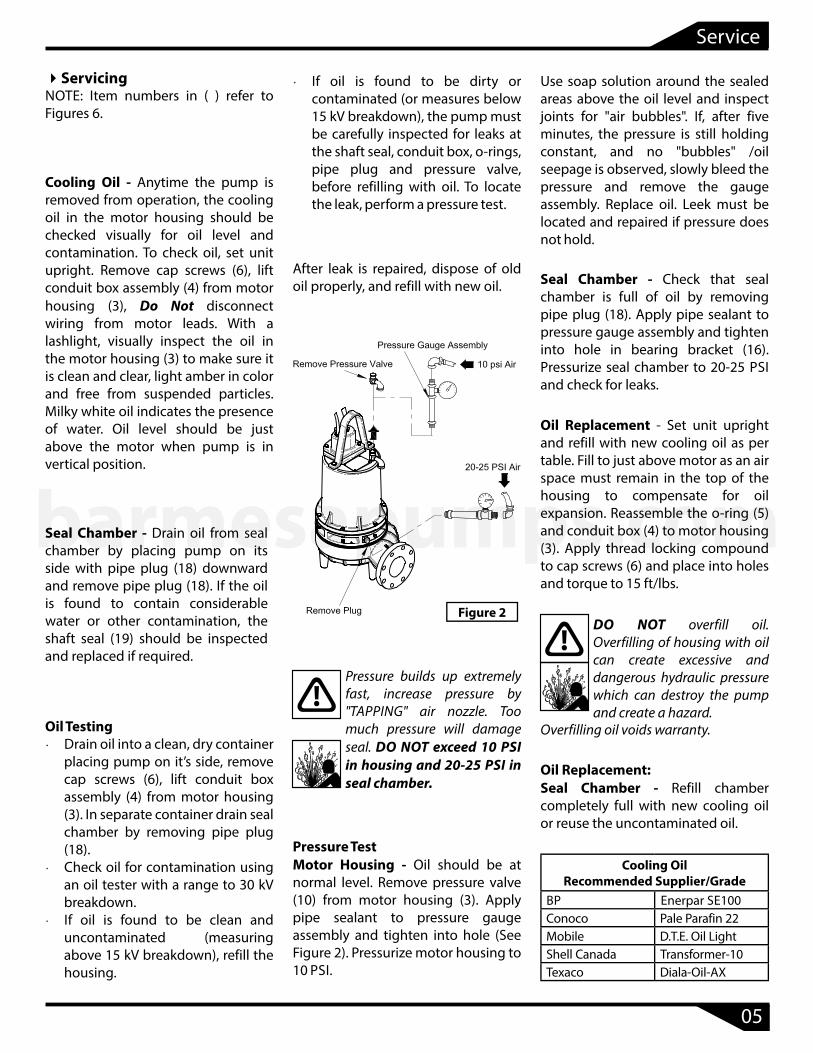
Cooling Oil - Anytime the pump is removed from operation, the cooling oil in the motor housing should be checked visually for oil level and contamination. To check oil, set unit upright. Remove cap screws (6), lift conduit box assembly (4) from motor housing (3), Do Not disconnect wiring from motor leads. With a lashlight, visually inspect the oil in the motor housing (3) to make sure it is clean and clear, light amber in color and free from suspended particles. Milky white oil indicates the presence of water. Oil level should be just above the motor when pump is in vertical position.
Seal Chamber - Drain oil from seal chamber by placing pump on its side with pipe plug (18) downward and remove pipe plug (18). If the oil is found to contain considerable water or other contamination, the shaft seal (19) should be inspected and replaced if required.
After leak is repaired, dispose of old oil properly, and refill with new oil.
Use soap solution around the sealed areas above the oil level and inspect joints for "air bubbles". If, after five minutes, the pressure is still holding constant, and no "bubbles" /oil seepage is observed, slowly bleed the pressure and remove the gauge assembly. Replace oil. Leek must be located and repaired if pressure does not hold.
Seal Chamber - Check that seal chamber is full of oil by removing pipe plug (18). Apply pipe sealant to pressure gauge assembly and tighten into hole in bearing bracket (16). Pressurize seal chamber to 20-25 PSI and check for leaks.
Oil Replacement - Set unit upright and refill with new cooling oil as per table. Fill to just above motor as an air space must remain in the top of the housing to compensate for oil expansion. Reassemble the o-ring (5) and conduit box (4) to motor housing (3). Apply thread locking compound to cap screws (6) and place into holes and torque to 15 ft/lbs.
Oil Replacement:Seal Chamber - Refill chamber completely full with new cooling oil or reuse the uncontaminated oil.
NOTE: Item numbers in ( ) refer to Figures 6.
Servicing Ÿ If oil is found to be dirty or contaminated (or measures below 15 kV breakdown), the pump must be carefully inspected for leaks at the shaft seal, conduit box, o-rings, pipe plug and pressure valve, before refilling with oil. To locate the leak, perform a pressure test.
Oil TestingŸ Drain oil into a clean, dry container
placing pump on it’s side, remove cap screws (6), lift conduit box assembly (4) from motor housing (3). In separate container drain seal chamber by removing pipe plug (18).
Ÿ Check oil for contamination using an oil tester with a range to 30 kV breakdown.
Ÿ If oil is found to be clean and uncontaminated (measuring above 15 kV breakdown), refill the housing.
Pressure builds up extremely fast, increase pressure by "TAPPING" air nozzle. Too much pressure will damage seal. DO NOT exceed 10 PSI in housing and 20-25 PSI in seal chamber.
Pressure TestMotor Housing - Oil should be at normal level. Remove pressure valve (10) from motor housing (3). Apply pipe sealant to pressure gauge assembly and tighten into hole (See Figure 2). Pressurize motor housing to 10 PSI.
DO NOT overfill oil. Overfilling of housing with oil can create excessive and dangerous hydraulic pressure which can destroy the pump and create a hazard.
Overfilling oil voids warranty.
05
Service
Cooling OilRecommended Supplier/Grade
BP Enerpar SE100Conoco Pale Parafin 22Mobile D.T.E. Oil LightShell Canada Transformer-10Texaco Diala-Oil-AX
Figure 2
barmesapumps.com
DisassemblyImpeller and Volute - Disconnect power. Remove hex nuts (24) and vertically lift motor housing and seal plate assembly from volute (31). Clean out volute (31) if necessary. Inspect gasket (30) and replace if cut or damaged. Clean and examine impeller (27), for pitting or wear and replace if required. To remove impeller (27), remove cap screw (29) and washer (28). With a wheel puller, pull impeller straight of shaft and remove square key (13).
Moisture Probes - Drain oil from seal chamber, if not already done. Remove cap screws (9) and lifting handle (8). Set unit upside down on blocks to avoid damaging cables. Remove socket head cap screws (22) and lift seal plate (20), with seal’s (19) stationary, vertically from bearing bracket (16), do not damage seal. Check moisture sensor probes (35) for damage, replace by removing screws (38) and disconnecting wires (34). Then remove probes (35) from bearing bracket (16).
Diaphragm - with seal plate (20) removed, examine diaphragm (21) for ruptures or crackes. Replace diaphragm by removing capscrews (41) and plate (40). Clean vent holes in seal plate (20).
Shaft Seal - Remove outboard rotating member of seal (19), spring and inboard rotating member from shaft. Examine all seal parts.
Inspect seal for signs of uneven wear pattern on stationary members, chips and scratches on either seal face. DO NOT interchange seal components, replace the entire shaft seal (19). If replacing seal, remove stationary by prying out with lat screwdrive.
Motor and Bearings - Remove volute, impeller, seal plate and seal as previously stated and drain oil from motor housing (3). Position unit upright, using blocks to avoid resting unit on shaft. Remove cap screws (6) o-ring (5) and conduit box assembly (4) from motor housing (3). Note connections and then remove cable lead wires from motor lead wires and moisture and temperature sensor wires from control cable by removing connectors. Remove cap screws (12) and vertically lift the motor housing (3) from bearing bracket (16). Replace square ring (15) if damaged or cut. Remove the upper motor bolts and lift upper end bell from motor (1). Remove wave washer. Remove upper bearing (2) with a wheel puller if damaged or worn.
Vertically lift stator (1) from rotor/shaft. Inspect windings for shorts and resistance. Test the temperature sensors by checking for continuity between the black and white wires. If defective contact factory or motor service station. Pull motor rotor/shaft with bearing (14) from bearing bracket (16). Remove bearing (14) with a wheel puller if worn or damaged. If rotor or stator windings are defective, replace the complete motor.
ReassemblyBearings - Replace bearings, being careful not to damage the rotor or shaft. If equipped, fiill notch should face the rotor core for both upper and lower bearings.
Apply adhesive compound to the shaft and press bearing (14) onto shaft, position squarely onto the shaft applying force to the inner race of bearing only, until bearing seats on shoulder of the shaft. In the same manner, assemble upper bearing (2) to shaft.
Motor - Slide rotor with bearing (14) into bearing bracket (16) until bearing seats on the bottom. Position motor housing and stator into pilot, install wave washers in upper end bell.
IMPORTANT! Special wave washers in upper motor housing are required to compensate for shaft expansion. These washers must be properly reinstalled to give the required constant down force on the motor shaft.
Position upper motor end bell aligning holes and thread cap screws into bearing bracket (16) and torque to 16 ft/lbs. Place all motor leads above the motor. Position square ring (15) on bearing bracket (16) and lower housing (3) over motor and into pilot, aligning handle so that it is parallel to motor end bell reliefs. Apply thread locking compound to threads on cap screws (12) and place into holes and torque to 24 ft/lbs.
Seal/Diaphragm - (See Figure 3) Clean and oil seal cavities in bearing bracket (16) and seal Plate (20). Lightly oil (Do not use grease) outer surface of inboard and outboard stationary members of seal (19). Press inboard stationary member f i rmly into bearing bracket (16) and outboard stationary into seal plate (20), using a seal pusher tool. Nothing but the seal pusher tool is to come in contact with seal face.
IMPORTANT! - All parts must be clean before reassembly.
Handle seal parts with extreme care. DO NOT damage lapped surfaces.
06
Service
barmesapumps.com

Be sure the stationary members are in straight and that the rubber ring is not out of it’s groove. Lightly oil (Do not use grease) shaft and inner surface of bellows on rotating member. With lapped surface facing bearing bracket (16), slide rotating member onto shaft using seal pusher tool, until lapped faces are together. It is extremely important to keep seal faces clean during assembly. Dirt particales lodged between faces will cause the seal to leak.
Be sure driving lugs in retainer are matched in rotating member of seal (19). Place spring over shaft and in place on rotating member, making sure it is seated in retainer and not cocked or resting on bellows tail. Lightly oil shaft and inner surface of outboard rotating member.
Spring should be properly engaged in both retainers.
Reassemble the diaphragm (21) with "bulg" facing seal plate (20). Place plate (40) on diaphragm (21) and insert capscrews (41) into plate and tighten.
Place seal plate (20) over shaft onto bearing bracket (16), being careful not to damage outboard stationary member and align holes for cap screws (22).
Conduit Box Assembly - Check power (32) and control cables (33) for crackes or damage and replace complete conduit box (4) if required. (See Figure 4) Bring motor wires through opening in top of motor housing (3), check sleeving and replace if damaged. Position square ring (5) in conduit box (4) and reconnect leads using connectors and insulators. See Figures 5, for wiring schematics.
Refill with cooling oil. Position conduit box (4) with square ring (5) on motor housing. Apply thread locking compound to cap screws (6) threads and torque to 16 ft/lbs.
Figure 3
Figure 4
IMPORTANT! - Hammering on the seal pusher tool will damage the seal face.
07
Service
With tail section toward bearing bracket (16), slide rotating member onto shaft with seal pusher tool until retainer engages spring and spring is compressed slightly.
Thread cap screws (22) into bearing bracket (16) and tighten. Refill chamber with oil.
Remove gland nuts (32B) and (33B), friction rings (32C) and (33C), and grommets (32D) and (33D) from conduit box (4), inspect and replace if damaged (See Figure 4). Reassemble by inserting one friction ring, grommet, one more friction ring and gland nut into conduit box. Torque gland nuts to 15 ft/lbs to prevent leakage.
barmesapumps.com

Impeller and Volute - Install impeller (27) by appling a thin film of oil to motor shaft and slide impeller straight onto shaft, keeping keyways lined up. Drive key (13) into keyway. Locate washer, apply thread lock primer (such as Loctite® Primer T), let set per manufacturer's directions. Apply thread locking compound to threads on cap screw (29), and thread into shaft and torque to 35 ft/lbs.
Place gasket (30) on volute and install impeller and motor assembly over studs and onto volute (31). Apply thread locking compound to threads of studs (23) and thread nuts (24) onto studs and torque to 24 ft/lbs. Check for binding by rotating impeller. Clearance between the impeller and volute should be approximately 0.012 inch.
08
Service
G T1 T7 T2 T8 T3 T9 T4 T5 T6
G L1 L2 L3
GRE
EN
BLA
CK
RED
WH
ITE
MOTOR LEADS
THREE-PHASE 208/230V AC
Cable Motor Lead NumberGreen GreenBlack 1 and 7Red 2 and 8
White 3 and 94, 5 and 6 together
Figure 5
T2 T3 T4 T7 T5 T8 T6 T9
G L2 L3
RED
WH
ITE
MOTOR LEADS
T1
L1
BLA
CK
G
G
GRE
EN
THREE-PHASE 460V AC
Cable Motor Lead NumberGreen GreenBlack 1Red 2
White 34 and 7 together5 and 8 together6 and 9 together
Figure 5
G
G
GRE
EN
P1 P2
L1
BLAC
K
L2
WH
ITE
THERMOSTATN/C
WH
ITE
WH
ITE
N/O
S1 S2
L3
RED
L4O
RAN
GE
SEN
SOR
SEN
SOR
ORA
NG
E
ORA
NG
E
TEMPERATURESENSOR
MOISTURESENSOR
CONTROL CABLE
Control Cable Lead NumberBlack L1 (Temperature)White L2 (Temperature)Red L3 (Moisture)
Orange L4 (Moisture)Green Ground
Figure 5
barmesapumps.com
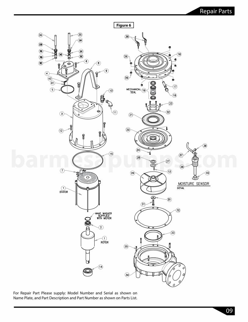
Figure 6
09
Repair Parts
barmesapumps.com
For Repair Part Please supply: Model Number and Serial as shown on Name Plate, and Part Description and Part Number as shown on Parts List.

10
Parts List
barmesapumps.com
For Repair Part Please supply: Model Number and Serial as shown on Name Plate, and Part Description and Part Number as shown on Parts List.
40
40

Risk of electric shock. Always disconnect the pump from the power source before handling inspections or repairs.
Symptom Possible Cause(s) Corrective Action
Pump will not run
1. Poor electrical connection, blown fuse, tripped breaker or other interruption of power; improper power supply2. Motor or switch inoperative (go to manual operation)2a. Float movement restricted2b. Switch will not activate pump or is defective2c. Defective motor3. Insuffi cient liquid level
1. Check all electrical connections for security. Have electrician measure current in motor leads, if current is within ± 20% of locked rotor Amps, impeller is probably locked. If current is 0, overload may be tripped. Remove power, allow pump to cool, then re-check current.2a. Reposition pump or clean basin as required to provide adaquate clearance for float2b. Disconnect level control. Set ohmmeter for a low rang, such as 100 ohms full scale and connect to level control leads. Actuate level control manually and check to see that ohmmeter shows zero ohms for closed switch and full scale for open switch. (Float Switch)2c. Check winding insulation (Megger Test) and winding resistance. If check is outside of range, dry and re-check. If still defective, replace per service instructions.3. Make sure liquid level is above the pump4. Re-check all sizing calculations to determine proper pump size.5. Check discharge line for restrictions, including ice if line passes through or into cold areas.6. Remove and examine check valve for proper installation and freedom of operation7. Open valve8. Check impeller for freedom of operation, security and condition. Clean impeller cavity and inlet of any obstruction9. Loosen union slightly to allow trapped air to
escape. Verify that turn-off level of switch is set so that the suction is always flooded. Clean vent hole10. Check rotation. If power supply is three phase, reverse any two of three power supply leads to ensure proper impeller rotation11. Repair fixtures as required to eliminate leakage12. Check pump temperature limits and fluid temperature13. Replace portion of discharge pipe with flexible connector or tighten existing piping.14. Turn to automatic position15. Check for leaks around basin inlet and outlets
Pump will not turn off
2a. Float movement restricted2b. Switch will not activate pump or is defective4. Excessive inflow or pump not properly sized for
application9. Pump may be air locked causing pump not to flow14. H-O-A switch on panel is in "HAND" position
Pump hums but doesn’t run1. Incorrect low voltage8. Impeller jammed or loose on shaft, or inlet plugged
Pump delivers insufficient capacity
1. Incorrect low voltage4. Excessive inflow or pump not properly sized for application5. Discharge restricted6. Check valve partially closed or installed backwards7. Shut-off valve closed8. Impeller jammed or loose on shaft, or inlet plugged9. Pump may be air locked causing pump not to flow10. Piping fixtures leaking or discharge before the nozzle
Pump cycles too frequently or runs periodically when f ixtures are not in use
6. Check valve partially closed or installed backwards11. Fixtures are leaking15. Ground water entering basin
Pump shuts of f and turns on independent ofswitch, (trips thermal overload protector). CAUTION! Pump may start unexpectedly. Disconnect power supply.
1. Incorrect low voltage4. Excessive inflow or pump not properly sized for application8. Impeller jammed or loose on shaft, or inlet plugged12. Excessive water temperature (internal protection only)
Pump operates noisily or vibrates excessively
2c. Worn bearings, motor shaft bent5. Debris in impeller cavity or broken impeller10. Pump running backwards13. Piping attachments to building structure too loose or rigid
NOTE: Barmesa Pumps assumes no responsibility for damage or injury due to disassembly in the field. Disassembly of the pumps or supplied accessories other than at Barmesa Pumps or its authorized service centers, automatically voids warranty.
11
Troubleshooting Chart
barmesapumps.com

BARMESA PUMPSFACTORY WARRANTY
Barmesa Pumps warrants that products of our manufacture will be free of defects in material and workmanship under normal use and service for 18 months from date of manufacture or 12 months from installation date whichever occurs first. This warranty gives you specific legal rights, which vary from state to state.
This warranty is a limited warranty, and no warranty related claims of any nature whatsoever shall be made against Barmesa Pumps, until the ultimate consumer or his/her successor notifies us in writing of the defect and delivers the product and/or defective part(s) freight prepaid to our factory or nearest authorized service station as instructed by Barmesa Pumps. THERE SHALL BE NO FURTHER LIABILITY, WHETHER BASED ON WARRANTY, NEGLIGENCE OR OTHERWISE. PRODUCT SHALL BE EITHER REPLACED OR REPAIRED AT THE ELECTION OF BARMESA PUMPS. Guarantees relating to performance specifications provided in addition to the foregoing material and workmanship warranties on a product manufactured by Barmesa Pumps, if any, are subject to possible factory testing. Any additional guarantees, in the nature of certified performance specifications or time frame must be in writing and such writing must be signed by our authorized factory manager at time of order placement and/or at time of quotation. Due to inaccuracies in field testing and should a conflict arises between the results of field testing conducted by or for the user, Barmesa Pumps reserves the right to have the product returned to our factory for additional testing.
This warranty shall not apply when damage is caused by (1) improper installation, (2) improper voltage, (3) lightning, (4) excessive sand or other abrasive material, (5) corrosion build-up due to excessive chemical content or (6) uncontrollable acts of god. Any modification of the original equipment will also void the warranty. We will not be responsible for loss, damage or labor cost due to interruption of service caused by defective pumps, parts or systems. Barmesa Pumps will not accept charges incurred by others without our prior written approval.
This warranty is void if our inspection reveals the product was used in a manner inconsistent with normal industry practice and/or our specific recommendations. The purchaser is responsible for communication of all necessary information regarding the application and use of the product. UNDER NO CIRCUMSTANCES WILL WE BE RESPONSIBLE FOR ANY OTHER DIRECT OR CONSEQUENTIAL DAMAGES, INCLUDING BUT NOT LIMITED TO TRAVEL EXPENSES, CONTRACTOR FEES, UNAUTHORIZED REPAIR SHOP EXPENSES, LOST PROFITS, LOST INCOME, LABOR CHARGES, DELAYS IN PRODUCTION, IDLE PRODUCTION, WHICH DAMAGES ARE CAUSED BY ANY DEFECTS IN MATERIAL AND/OR WORKMANSHIP AND/OR DAMAGE OR DELAYS IN SHIPMENT. THIS WARRANTY IS EXPRESSLY IN LIEU OF ANY OTHER EXPRESS OR IMPLIED WARRANTY. No rights extended under this warranty shall be assigned to any other person, whether by operation of law or otherwise, without our prior written approval.
IMPORTANT!If you have a claim under the provision of the warranty, contact Barmesa Pumps or your
authorized Barmesa Pumps Distributor:[email protected]
www.barmesapumps.com