INSTALLATION OPERATION MAINTENANCE INSTRUCTIONS … · Westinghouse LL. 41-7 48.1 s INSTALLATION...
32
Westinghouse LL. 41-748.1 s INSTALLATION • OPERATION • MAINTENANCE INSTRUCTIONS TYPE KLF-1 LOSS-OF-FIELD RELAY C A U T I ON Before putting protective relays into serv- ice , remove all blocking which may have been in- serted for the purpose of securing the parts during shipment, make sure that all moving parts operate freely, inspect the contacts to see that they are clean and close properly, and operate the relay to check the settings and electrical connections. APPL I CAT I ON The KLF-1 relay is a single-phase relay con- nected to the a-c side of a synchronous machine and contains three units connected so that the operation of two units sounds an alarm warning the operator of a low excitation condition, and the additional opera- tion of the third unit sets up the trip circuit. The re- lay can be applied without modification to all types of synchronous machines. This relay is used where a wye-wye potential transformer connection is avail- able. CONSTRUCT! ON The relay consists of two air-gap transformers (compensators), two tapped auto-transformers, one reactor, one cylinder-type distance unit, directional unit with adjustable resistor, an undervoltage unit with adjustable resistor; t elephone relay, and an res indicating contactor switch. Compensator The compensators which are designated T A and Tc are two-winding air gap transformers (Fig. 2). The primary or current winding of the long-reach-com- pensator T A has seven taps which terminate at the blo. They are marked 2.4, 3.16, 4.35, 5.93, 8.3, 11.5, 15.8. The primary winding of the short-reach compensator Tc also has seven taps which terminate at this tap block. They are marked 0 .0, 0.91, 1.27, 1.82, 2.55, 3.64, 5.1. A voltage is induced in the secondy which is proportional to the primary tap SUPERSEDES LL. 41-748.1A *Denotes change from superseded issue and current magnitude. This proportionality is estab- lished by the cross sectional area of the laminated steel core, the length of an air gap which is located in the center of the coil, and the tightness of the laminations. A ll of these factor s which influence the secondy voltage proportionality have been pre- cisely set at the factory. The clamps which hold the laminations should not be disturbed by either tighten- ing or l oosening the clamp screws. The secondary winding is connected in series with the relay terminal voltage. Thus a voltage which is propor tiona! to the line current is added vectorially to the relay terminal voltage. A uto- Transf ormer The auto-transformer has three taps on its main winding, S, which are numbered 1, 2, and 3 on the tap block. A tertiary winding M has four taps which may be connected additivelY or subtractively to inversely modify the S setting by any value from -15 to +15 percent in steps of 3 percent. The sign of M is negative when the R lead is above the L lead. M is positive when L is in a tap location which is above the tap location of the R lead. The M setting is determined by the sum of per unit values between the R and L lead. The actual per unit values which appear on the tap plate between taps are 0 . .03, .06, and . 06. The auto-transformer makes it possible to expand the basic ranges of the long and short reach co pensators by a multiplier of 1 ± S M . A ny relay ohm setting can be made within ± 1.5 percent from 2.08 ohms to 56 ohms for the long reach and from .79 ohms to 18 ohms for the short reach. Impedance Tripping Unit The distance unit is a four pole induction cyl - EFFECTI VE MARCH 1966 www . ElectricalPartManuals . com
Transcript of INSTALLATION OPERATION MAINTENANCE INSTRUCTIONS … · Westinghouse LL. 41-7 48.1 s INSTALLATION...

Westinghouse LL. 41-7 48.1 s
INSTALLATION • OPERATION • MAINTENANCE
INSTRUCTIONS TYPE KLF-1 LOSS-OF-FIELD RELAY
CAU T I ON Before putting protective relays into service , remove all blocking which may have been inserted for the purpose of securing the parts dur ing shipment, make sure that all moving parts operate freely, inspect the contacts to see that they are clean and close properly, and operate the relay to check the settings and electrical connections.
APPLI CAT I ON
The KLF-1 relay is a single-phase relay connected to the a-c side of a synchronous machine and contains three units connected so that the operation of two units sounds an alarm warning the operator of a low excitation condition, and the additional operation of the third unit sets up the trip circuit. The relay can be applied without modification to all types of synchronous machines. This relay is used where a wye-wye potential transformer connection is available.
CONSTRUCT! ON
The relay consists of two air-gap transformers (compensators), two tapped auto-transformers, one reactor, one cylinder-type distance unit, directional unit with adjustable resistor, an undervoltage unit with adjustable resistor; t elephone relay, and an res indicating contactor switch.
Compensator
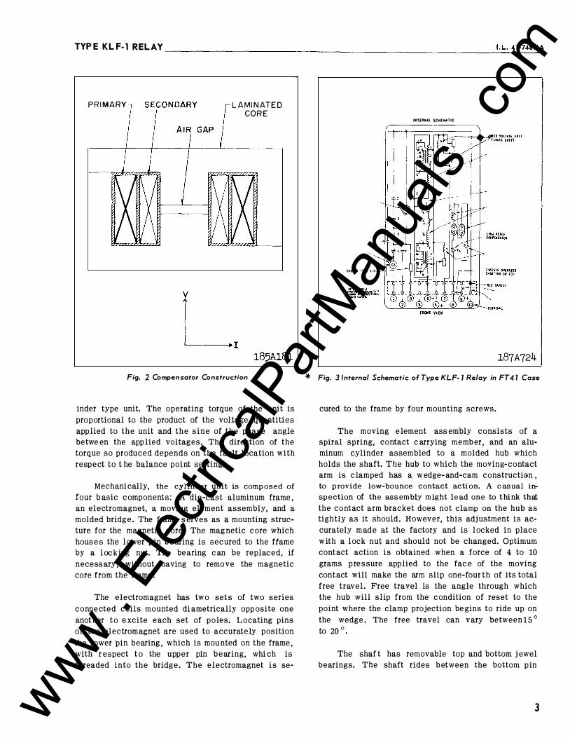
The compensators which are designated T A and Tc are two-winding air gap transformers (Fig. 2). The primary or current winding of the long-reach-compensator T A has seven taps which terminate at the block. They are marked 2.4, 3.16, 4.35, 5.93, 8.3, 11.5, 15.8. The primary winding of the short-r.each compensator Tc also has seven taps which terminate at this tap block. They are marked 0.0, 0.91, 1.27, 1.82, 2.55, 3.64, 5.1. A voltage is induced in the secondary which is proportional to the primary tap
SUPERSEDES LL. 41-748.1A *Denotes change from superseded issue
and current magnitude. This proportionality is established by the cross sectional area of the laminated steel core, the length of an air gap which is located in the center of the coil, and the tightness of the laminations. All of these factor s which influence the secondary voltage proportionality have been precisely set at the factory. The clamps which hold the laminations should not be disturbed by either tightening or l oosening the clamp screws.
The secondary winding is connected in series with the relay terminal voltage. Thus a voltage which is propor tiona! to the line current is added vectorially to the relay terminal voltage.
Auto- Transformer
The auto-transformer has three taps on its main winding, S, which are numbered 1, 2, and 3 on the tap block. A tertiary winding M has four taps which may be connected additivelY or subtractively to inversely modify the S setting by any value from -15 to +15 percent in steps of 3 percent.
The sign of M is negative when the R lead is above the L lead. M is positive when L is in a tap location which is above the tap location of the R lead. The M setting is determined by the sum of per unit values between the R and L lead. The actual per unit values which appear on the tap plate between taps are 0 . . 03, .06, and . 06.
The auto-transformer makes it possible to expand the basic ranges of the long and short reach com-
pensators by a multiplier of 1 ±
S M
. Any relay ohm
setting can be made within ± 1 .5 percent from 2.08 ohms to 56 ohms for the long reach and from . 79 ohms to 18 ohms for the short reach.
Impedance T r ipping Unit
The distance unit is a four pole induction cyl -
EFFECTI VE MARCH 1966 www . El
ectric
alPar
tMan
uals
. com

TYPEKLF-lRELAY ______________________________________________________ __
2
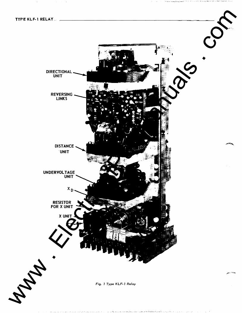
DIRECTIONAL UNIT
REVERSING LINKS
UNIT
UNDERVOLTAGE UNIT
RESISTOR FOR X UNIT
X UNIT ICS
I
Fig. 1 Type KLF-1 Relay
www . El
ectric
alPar
tMan
uals
. com

TYPEKLF-1 RELAY ______________________________________________________ �I.=L�.4�1�- 7� ��·�1 B
LAMINATED CORE
Fig. 2 Compensator Construction
inder type unit. The operating torque of the unit is proportional to the product of the voltage quantities applied to the unit and the sine of the phase angle between the applied voltages. The direction of the
* torque so produced depends on the impedence vector seen by the relay with respect to its characteristic circle.
Mechanically, the cylinder unit is composed of four basic components: A die-cast aluminum frame, an electromagnet, a moving element assembly, and a molded bridge. The frame serves as a mounting structure for the magnetic core. The magnetic core which houses the lower pin bearing is secured to the ffame by a locking nut. The bearing can be replaced, if necessary, without having to remove the magnetic core from the frame.
The electromagnet has two sets of two series connected coils mounted diametrically opposite one another to excite each set of poles. Locating pins on the electromagnet are used to accurately position the lower pin bearing, which is mounted on the frame, with respect t o the upper pin bearing, which is threaded into the bridge. The electromagnet is se-
INTERNAL SCHEMATIC
TElEPIIOMERELAY
2�g� � :��sv��D�C. lL=--J---1 60000-2SOV.D.C.
FROHT VIEW
187A724 Fi g. 3 /nterna/ Schematic of Type KLF-1 Relay in FT41 Case
cured to the frame by four mounting screws.
The moving element assembly consists of a spiral spring, contact carrying member, and an aluminum cylinder assembled to a molded hub which holds the shaft. The hub to which the moving-contact arm is clamped has a wedge-and-cam construction , to provide low-bounce contact action. A casual inspection of the assembly might lead one to think that the contact arm bracket does not clamp on the hub as tightly as it should. However, this adjustment is accurately made at the factory and is locked in place with a lock nut and should not be changed. Optimum contact action is obtained when a force of 4 to 10 grams pressure applied to the face of the moving contact will make the arm slip one-four th of its total free travel. Free travel is the angle through which the hub will slip from the condition of reset to the point where the clamp projection begins to ride up on the wedge. The free travel can vary between 1 5 ° to 20 o.
The shaf t has removable top and bottom jewel bearings. The shaft rides between the bottom pin
3 www . El
ectric
alPar
tMan
uals
. com

TYPEKLF-lRELAY ______________________________________________________ ___
I
GEN
I•·
100% P.F. LOAD PHASE R O TATION 1,2,3
z TA
MA L-----------�-,f�'rSA
f-FUSE KLF-1 RELAY SEPA RATELY F R OM ALL OTHER SECONDAR Y BURDENS
43 SWITCH (OPTIONAL)
X- DENOTES CONTACTS CLOSED
D.C. TRIP BUS PC'S
f� X
-¥- ..ill. I
3 43 41 52 ... TO ALARM
52
NEG.
DEVICE N UMBER CHART 40• LOSS OF FIELD RELAY, T YP E KLF -1
D- DIRECTIONAL UNIT IN T YPE KLF-1 ICS- INDICATING CONTACTOR SWITCH IN
TYPE KLF·l RELAY TA- LONG REACH COMPENSATOR
T C- SHORT REACH COMPENSATOR V- VOLTAGE UNIT IN T YPE KLF-1 RELAY
X -TELEPHONE RELAY IN TYPE KLF-1 RELAY Z- IMPEDANCE UNIT IN T YPE KL F-1 RELAY
43- ON-OFF CUT-OUT SWITCH 52- POWER CIRCUIT B REAKER A - BREAKER AUX. SWITCH
TC- B REAKER TRIP COIL
X �" CONTACT CLOSING ZONE
SYSTEM R-X DIAGRAM
I
J: 3 2 ! -I,
DISTANCE UNIT VECTORS FOR 100% P.F. GENERATOR OUTPUT
DIRECTIONAL UNIT VECTORS FOR 100% P.F. GENERATOR OUT PUT
292B471. Fig. 4 External Schematic of Type KLF- 1 Relay
bearing and the upper pin bearing with the cylinder rotating in an air gap formed by the electromagnet and the magnetic core. The stops are an integral part of the bridge.
The bridge is secured to the electromagnet and frame by two mounting screws. In addition to holding the upper pin bearing, the bridge is used for mounting the adjustable stationary contact housing, This stationary contact has . 002 to . 006 inch follow which is set at the factory by means of the adjusting screw. After the adjustment is made the screw is sealed in position with a material which flows around the threads and t.hen solidifies. The stationary contact housing is held in position by a spring type clamp. The spring adjuster is located on the underside of the bridge, and is attached to the moving contact arm by a spiral spring. The spring adjuster is also held in place by a spring type clamp.
When contacts close, the electrical connection is made through the stationary contact housing clamp, to the moving contact, through the spiral spring and out to the spring adjuster clamp.
4
Directi onal Unit
The directional unit is an induction cylinder unit operating on the interaction between the polarizing circuit flux and the operating circuit flux.
Mechanically, the directional unit is composed of the same basic components as the distance unit: A die-cast aluminum frame, an electromagnet, a moving element assembly, and a molded bridge.
The electromagnet has two series -connected polaFizing coils mounted diametrically opposite one another; two series-connected operating coils mounted diametrically opposite one another; two magnetic adjusting plugs; upper and lower adjusting plug clips, and two locating pins. The locating pins are used to accurately position the lower pin bearing, which is threaded into the bridge. The electromagnet is secured to the frame by four mounting screws.
The moving element assembly consists of a spiral spring, contact carrying member, and aluminum cylinder assembled to a mo lded hub which holds the shaft. The shaft has removable top and
www . El
ectric
alPar
tMan
uals
. com

TYPEKLF-1 RELAY------------------------------------------------------���.L�·�41�-7�4�·�1B
+X +X +X
+ zc
-R -R
-x -x -x
(Q) WITH %c • 0 (b) WITH Zc > 0 tel WITH Zc < 0
Fig. 5 R·X Diagram Characteristics with Various Zc Compensator Settings
bottom jewel bearings. The shaft rides between the bottom pin bearing and the upper pin bearing with the cylinder rotating in an air gap formed by the electromagnet and the magnetic core.
The bridge is secured to the electromagnet and frame by two mounting screws. In addition to holding the upper pin bearing, the bridge is used for mounting the adjustable stationary contact housing . The sta· tionary contact housing is held in position by a spring type clamp. The spring adjuster is located on the underside of the bridge and is attached to the moving contact arm by spiral spi:ing. The spring adjuster is also held in place by a spring type clamp.
Undervoltage Unit
The voltage unit is an induction-cylinder unit.
Mechanically, the voltage unit is composed like the directional unit, of four components: A die cast aluminum frame, an electromagnet, a moving element assembly, and a molded bridge.
The electromagnet has two pairs of voltage coils. Each pair of diametrically opposed coils is connected in series. In addition one pair is in series with an parallel R-C combination. These sets are in parallel as shown in Fig. 3. The adjustable resistor serves not only to shift the phase angle of the one flux with respect to the other to produce torque, but it also provides a pick-up adjustment.
Otherwise the undervoltage unit is similar in its construction to the directional unit.
Ali, •0
YPOL(REF)• jKv10
CONTA:: .
--CLO�g �\lop • Y10
jK (-� Zc)
� I I { YPOL ( REF.)
JKY10 CONTACT CLOSES/"
Yop ,-.+-f..._ . __ ..,vi O I \ I !
RELAY-TYPE KLF-1 VECTOR DIAGRAMS
188A320 Fig. 6 Effect of Compensator Voltages (Zc is positive)
Telephone Relay
The telephone relay (X) has a slow drop-out characteristic. When energized, the solenoid core attracts an iron right-angle armature bracket which in turn opens the break contacts. In actual service, the relay is normally energized holding the break con· tacts open. (Note: the make contacts are not used.)
Drop-out delay adjustment is obtained by varying the air-gap between the armature and the core.
Indicat ing Contactor Sw itch Unit ( I CS}
The d·c indicating contactor switch is a small clapper-type device. A magnetic armature, to which leaf-spring mounted contacts are attached, is attracted to the magnetic core upon energization of the switch. When the switch closes, the moving contacts brid�e two stationary contacts, completing the trip circuit. Also during this operation two fingers on the armature deflect a spring located on the front of the switch, which allows the operation indicator target to drop. The target is reset from the outside of the case by a push rod located at the bottom of the cover.
5 www . El
ectric
alPar
tMan
uals
. com

TYPEKLF-1 RELAY ____________________________________ ____________________ __
� " � ;:: � I!! ,_ � "' .., Cl.
� �
0
-.2
-.4
PER UNIT KW .6 1.0
-.8�--�----+----+----4---�-----r--�
� - 1.0 '--------'-----.J.._------'------L-------'�---L-----'
185Al83 Fig. 7 Typical Machine Capacity Curves Plotted on a Per
Unit K VA Basis ( 183,500 K VA, 45tt H2, 18KV, 0.9
pf, 0.64 SCR, inner-coo led, 3600 rpm. )
The front spring, in addition to holding the target, provides restraint for the armature and thus controls the pickup of the switch.
OPERATI ON
The relay is connected and applied to the system as shown in Fig. 4. The directional unit closes its Cont acts for lagging var flow into the machine. Its zero torque line has been set at -13 ° from the R-axis. Its primary function is to prevent operation of the relay during external faults . The impedance unit
closes its contacts when, as a result of reduction in excitation, the impedance of the machine as viewed from its terminals is less than a predetermined value. The operation of both the impedance and directional units sounds an alarm, and the additional operation of the undervoltage unit trips the machine. As shown in Fig. 4, the contacts of all three units are con nected in series across a telephone type relay designated X, which provides approximately 15 cycles time delay on dropout before energizing the trip coil . This time delay is to insure positive contact coordination under all possible operating conditions. During normal conditions, all contacts are open.
Principle of Distance Unit Operation
The distance unit is an induction cylinder unit having directional characteristics. Operation depends on the phase relationship between magnetic fluxes in the poles of the electromagnet.
6
-.2
-.of
z .. -.6
-.1
IIESISTANO! IN PER UNIT
TYPICAL MACHINE CAPABILITY CURVES AND SAMPLE '"-F RELAY SETTING, PLOTTED ON
A. PER UNIT IMP�DANCE BASIS
185Al84 Fig. 8 Typical M ach ine Capability Curves and Sampl e
KL F- 1 Settings- P er Unit Impedance
One set of opposite poles, designated as the operating poles are energized by voltage V 10 modified by a voltage derived from the long reach compens ator
T A· The other set of poles (polarizing) are energized by the same voltage V10 except modif ied by a voltage derived from the short reach compensator Tc: The flux in the polarizing pole is so adjusted that the unit closes its contacts whenever flux in the operating set of poles leads the flux in the polarizing set.
Reach of the distance unit is determined by compensators TA and Tc as modified by auto-transformer settings. Compensators T A and T c are de signed so that its mutual impedance ZA or Zc has known and adjustable values as described below under CHARACTERISTICS and SETTINGS. The mutual impedance of a compensator is defined here as the ratio of secondary induced voltage to primary current and is equal to T. Each secondary compensator voltage is in series with the voltage V 10. Compensator voltages are equal to I 1 Z A for long reach compensator and I 1 Z c for short reach compensator, where I, is the relay current.
www . El
ectric
alPar
tMan
uals
. com

TYPEKLF-1 RELAY _______________________________________________________ I_.L_._4_1 •7_a_._1 8
Fig. 5 shows how the compensation voltages I 1 Z A and I 1Zc influence the R-X circle. Note that that Z A independently determines the "long reach", while Zc independently fixes the "short reach". With the reversing links in the normal position ( +ZC) the circle includes the origin; with the opposite link position (-Zc) the circle misses the origin. The following paragraphs explain this compensator action.
Referring to Fig. 4 note that X c and C c cause the polarizing voltage to be shifted 90 o in the leading direction. Thus, when the current is zero, polarizing voltage V POL leads the operating voltag� Vop by 90 °, as shown in Fig. 6(a). This relation produces restraining torque. To illustrate how Z A fixes the long reach, assume a relay current which leads V 10 by 90 o and of sufficient magnitude to operate the relay. This means the apparent impedance is along the -X axis. Note in Fig. 6(b) that the Z A compensation reverses the operating voltage phase position. The relay balances when this voltage is zero. Note that this balance is unaffected by the Z c compensa tion, since this compensation merely increases the size of VpoL.
For lagging current conditions note in Fig. 6(c) how V POL is reversed by the Zc compensation. In this case the ZA compensation has no effect on the balanc� point. This explains why the short reach point is fixed independently by Zc.
Fig. 6 assumes that Zc is positive (circle includes origin). If the current coil link is reversed, the compensation becomes +Z C· In Fig. 6(b) this chan ge would result in, V po L being reduced rather increased by the compensation. As the current increases V POL will finally be reversed, reestablishing restraining torque. Thus, the current need not reverse in order to obtain a "short-reach" balance point. Instead the apparent impedance need only move tow ards the origin in the -X region to find the balance point. Therefore, the circle does not include the origin with a reversed link position.
CHARACTER ! ST I CS
The type KLF relay is available in one range.
Distance Unit
The distance unit can be set to have characteristic circles that pass through origin, include it, or exclude it, as shown in Fig. 5.
The ZA and Zc values are determined by compensator settings and modified by autotransformer
settings S, L, and R. The impedance settings in ohms reach can be made for any value from 2.08 to 56 ohms for Z A· and from 0. 79 ohm to 18 ohms for Zc in steps of 3 percent.
The taps are marked as follows:
2.4, 3.16, 4.35, 5.93, 8.3, 11.5, 15.8
0.0, 0.91, 1.27, 1.82, 2.55, 3.64, 5 . 1
1, 2, 3
(MA• Me)
± values between taps .03, .06, .06
Directional Unit
The KLF relay is designed for potential polarization with an internal phase shifter, so that maximum torque occurs when the operating current leads the polarizing voltage by 43 degrees. The 'minimum pickup has been set by the spring tension to be approximately 1 volt and 5 ampere at maximum torque angle.
Undervoltage Unit
The undervoltage unit is designed to close its contacts when the voltage is lower than the set value. The undervoltage unit is energized with V3o-voltage. The contacts can be adjusted to close over the range of 65 to 85 percent of normal system voltage. The dropout ratio of the unit is 98 percent or higher.
Trip Circuit
The main contacts will safely close 30 amperes at 250 volts d.c. and the seal-in contacts of the indicating contactor switch will safely carry this current long enough to trip a circuit breaker.
The indicating contactor switch has two taps that pr ovide a pick-up setting of 0. 2 or 2 amperes. To change taps requires connecting the lead located in front of the tap block to the desired setting by means of a screw connection.
Trip Circuit Constant
Indicating Contactor Switch (ICS)
0.2 ampere tap - 6.5 ohm d-e resistance 2.0 ampere tap - 0.15 ohm d-e resistance
7 www . El
ectric
alPar
tMan
uals
. com

TYPEKLF·l RELAY ________________________________________________________ __
Burden
current @5 amps, 60 cycles
TA & Tc
SETTINGS
MAX. MIN.
ANGLE
VA OF LAG
12.05 58 ° 4. 17 36 °
Potential @.69 volts, (Phase-To Ground) 60 cycles
Phase 1 S == 1 6. 1 VA at 9 o current lag
S == 2 1 . 5 VA at 9 o current lag
S == 3 0. 7 VA at 9 o current lag
Phase 2 3. 18 VA at 48 ° current lag
Phase 3 2. 76 VA at 43 ° current lag
RATING
125 250
D·C Circuit
WATTS@ RATED
3.9 7. 8
Thermal Ratings
Potential: 75 volts (L-N) continuous
current: 8 amperes continuous 200 amperes for 1 second
SETTINGS CALCULATI ONS
Distance Unit
set the distance unit to operate before the steadystate stability limit is exceeded. Also, to allow maximum output without an alarm, set the distance unit to allow the machine to operate at maximum hydrogen pressure and 0 .95 per unit voltage (lowest voltage for which the capability curve applies). Where the maximum capability of the machine cannot be realized without exceeding the steady-state stability limit, set the distance unit to operate before the steadystate limit is exceeded. Capability curves similar to Fig. 7 are obtained from the generator manufacturer.
To determine the desired setting convert the capability curve of Fig. 7 to the impedance curve of
Fig. 8 by calculating ---- where VT is the per (KVA)c
8
unit terminal voltage and (KV A) c is the per unit output. If the capability curve is a circle the radius R 1 and offset C 1 of the inverse circle (VT == 1) can be calculated as follows:
1 c ==
--..---c--=c=--,.- £ C 2 R 2 c c
( 2)
(3)
where C 1 == distance of capabiltiy - circle center from origin of R-X diagram.
R 1 == radius of capability circle on R-X diagram.
Cc == distance of power-circle center from origin.
Rc == radius of power circle.
f) == offset angle
After plotting the steady-state stability limit and the machine capability curves on the R-X diagram, plot the relay circle between the stability limit and the capability curve. (Note in Fig. 8 that the relay circle cannot be plotted within the 60# - VT ==
0.95 curve, since the machine is beyond the steady state stability limit for these conditions. ) This plot defines the desired reach Z A and radius R of the relay circle. Then use the following pr ocedure to select tap settings.
where
1000 (kv) 2 Rc Zbas e == ------'-------'----=- ohms (kva) Rv
Zbase one per unit primary ohms/as seen from the relay
kv == rated phase-to-phase voltage of the machine.
kva == rated kva of the machine .
Rc == the current transfor mer ratio.
Ry == the potential transformer ratio.
www . El
ectric
alPar
tMan
uals
. com

TYPEKLF-1 RELAY __________________________________________ ______________ I._L_._41_·7_a_ . __ 1B
The actual settings, ZA and Z e. are:
Z A = (Z A per unit) x (Z base)
z e = (Zc per unit) x (Z base) =
(2R-ZA) x (Z base)
where R = radius of circle in per unit.
'l'he tap-plate settings are made according to equations:
where:
TS z A (orZe) = (5)
1 ± M
T = compensator tap value.
S = auto-transformer primary tap value.
M =auto-transformer secondary tap value .
(M is a per-unit value determined by taking the sum of the values between the L and the R leads. The sign is positive when L is above R and acts to lower the Z setting. The sign is negative when R is above L and acts to raise the Z setting).
The following procedure should be followed to obtain an optimum setting of the relay:
1. Select the lowest tap S which give a product of 18. 6S A greater than desired Z A and a product of 6S e greater than desired Ze.
2. Select a value of M that will most nearly make it equal to:
TS M = -- - 1.
z If the sign is negative, then the M taps are con
nected with the R lead above the L lead to raise the
setting.
Sample Cal cul ations
Assume that a KLF relay is to be applied to the following machine:
3-phase, 60 cycles, 3600 rpm, 18 kv, rated at 0.9 pf, 183, 500 KV A at 45 tt H2 .
Rc = 1400/1 R v = 150/ 1
If the recommended setting from Fig. 8 is used:
The relay circle needed for a particular set of machine capability curves may be obtained by trial and error using a compass. The offset and radius of the relay circle in fig. 8 were drawn by this method.
ZA per unit = 1.68 Ze per unit = 2R- ZA = 2 x 0 .94 - 1.68 = 0.20
2 1000(kv) Rc 1000 x ( 18) 2 x 1400 16.45
= ( 1)Zbase = =
(kva)Rv 183, 500 x 150 ohms
(2) ZA = ZA (per unit) (Zbase) = ( 1 .68) ( 16.45) = 27. 6 ohms
(3) Z e= Z e(per unit) (Zbase)=(0. 20) ( 16.45) = 3.29
ohms
To set ZA = 27.6
Step 1: The lowest tap SA for 18 .6 SA greater than ZA = 27. 6 is 2. Set SA in tap 2.
Step 2: TA nearest to 27.6 = 13.8 is TA = 15.8
2
Set T A in 15.8 tap TASA 15 .8 x 2
Step 3: MA = -- - 1 = - 1 = z 27.6
1.145- 1 = + . 145
Set M = + . 15. Place R lead in 0, L lead in upper . 06. The relay setting is now:
TASA 15 .8 x 2 3 1. 6 Actual ZA = = --- = 27. 5
1 ± M 1 + 0. 15 1. 15
This is 99.7% of the desired setting.
To set Zc = 3. 29 ohms:
Step 1: The lowest tap Se for 6Sc greater than 3. 29 is se = 1.
set se = 1
Step 2: Te nearest to 3. 29 = 3. 29 is 3. 64 1
Set Te in 3. 64 tap.
Tese 3.64 x 1
step 3: M e =-- - 1 = - 1 =1 . 107-1=
+ . 107
ze 3. 29
Hence, the nearest Me value is + . 12. Now set R lead in 0 .03 tap and L lead in the upper . 06 tap.
(Since Me has plus sign, lead L must be over R.)
3 .64 x· 1 Then, Ze = --- --- = 3. 25 ohms, or
1 + . 12
98. 8% of the desired value.
9 www . El
ectric
alPar
tMan
uals
. com

TYPEKLF-lREL AY ______________________________________________ ______ __ __
Undervolta.ge Unit
The undervoltage unit is usually set to a value corresponding to the minimum safe system voltage for stability. This voltage depends upon system constants and is usually between 70 and 80 percent. A higher value could be used if it is desired to trip the machine sooner upon loss of field. The undervoltage unit is set at the factory for 77 percent of system voltage, or 53 volts.
Note: An electrical check of this particular setting is outlined in this instruction leaflet, under the head ing ''Ace eptance Check'' .
SE TTING T H E R ELAY
The type KLF relay requires a setting for each of the two compensators T A and Tc, for each of the two auto-transformers primaries SA and Sc, and for the undervoltage unit.
Compensator ( T A and Tc)
Each set of compensator taps terminates in inserts which are grouped on a socket and form approximately three quarters of a circle around a center insert which is the common connection for all the taps. Electrical connections between common insert and tap inserts are made with a link that is held in place with two connector screws, one in the common and one in the tap.
A compensator tap setting is made by loosening the connector screw in the center. Remove the connector screw in the tap end of the link, swing the link around until it is in position over the insert for the desired tap setting, replace the connector screw to bind the link to this insert, and retighten the connector screw in the center. Since the link and connector screws carry operating cunent, be sure that the screws are turned to bind snugly.
Compensator T c requires an additional setting for including or excluding the origin of R-X diagram from the distance unit characteristic. If the desired characteristic is similar to that shown on Fig. 5b, the links should be set vertically in the + Tc arrow direction. If a characteristic similar to that shown in Fig. 5c is desired, set links horizontally in the - Tc arrow direction.
Auto- Transformer Primary ( SA and Sc)
Primary tap connections are made through a single lead for each transformer. The lead comes out
10
of the tap plate through a small hole located just below the taps and is held in place on the proper tap by a connector screw.
An S setting is made by removing the connector screw, placing the connector in position over the insert of the desired setting, replacing and tightening the connector screw. The connector should never make electrical contact with more than one tap at a time.
Auto- Transformer Secondary (M A and Me)
Secondary tap connections are made through two leads identified as L and R for each transformer . These leads come out of the tap plate each through a small hole, one on each side of the vertical row of M tap inserts. The lead connectors are held in place on the proper tap by connector screws.
Values for which an M setting can be made are from - . 15 to + . 15 in steps of .03. The value of a setting is the sum of the numbers that are crossed when going from the R lead position to the L lead position. The sign of the M value is determined by which lead is in the higher position on the tap plate. The sign is positive ( +) if the L lead is higher and negative (-) if the R lead is higher.
An M setting may be made in the following manner: Remove the connector screws so that the L and R leads are free. Determine from the following table the desired M value and tap positions. Neither lead connector should make electrical contact with more than one tap at a time.
Tabulated Settings
z M L Lead R Lead
0 . 87 TS + .15 Upper .06 0
0 . 89 TS + . 12 Upper .06 .03
0.92 TS + .09 Lower .06 0
0.94 TS + .06 Upper .06 Lower .06
0 .97 TS + .03 .03 0
TS 0 0 0
1.03 TS + .03 0 .03
1.06 TS - . 06 Lower .06 Upper . 06
1. 1 TS - . 09 0 Lower .06
1. 14 TS - . 12 .03 Upper .06
1. 18 TS - . 15 0 Upper .06
•
www . El
ectric
alPar
tMan
uals
. com

TYPEKLF-1 RELAY _______________________________________________________ I ._L ._4_1 _·7_� __ .1B
f POSITION 1- FOR-D-UNIT TEST ff POSITION 2-FOR V UNIT TEST
VARIABLE AUTO- TRANSFORMER ICS
A
�==�i=�==========�================��====�================�=====:�=======�}3 PHASE i � 120 VOLTS
292B545 Fig. 9 Diagram of Test Connections for K L F- 1 Relay
Undervol tage Unit
The voltage unit is calibrated to close its contact when the applied voltage is reduced to 53 volts. The voltage un it can be set to close its contacts from 40 volts to 70 volts by adjusting the re.sistor located in the rear, second from the bottom. The spiral spring is not disturbed when making any setting other than the calibrated setting of 53 volts.
Directional Setting
There is. no setting to be made on directional unit.
Indicating Contractor Switch (ICS)
No setting is required on the res unit except the selection of the 0 .2 or 2.0 ampere tap setting. This selection is made by connecting the lead lo· cated in front of the tap block to the desired setting by means of the connecting screw . When the relay energizes a 125 volt or 250 volt d.c. type WL relay switch, or equivalent, use the 0 . 2 ampere tap. For
48 volt d.c. applications set res in 2 ampere tap and use S1t304C209GO 1 type WL relay coil or equivalent.
INSTALLATION
The relays should be mounted on switchboard
panels or their equival ent in a location free from
dirt, moisture, excessive vibration, and heat. Mount
the relay vertically by means of the four mounting holes on the flange for semi-flush mounting or by means of the rear mounting stud or studs for projection mounting. Either a mounting stud or the mounting screws may be utilized for grounding the relay. The electrical connections may be made directly to the terminals by means of screws for steel panel mounting or the terminal studs furnished with the relay for thick panel mounting. The terminal studs may be easily removed or inserted by locking two nuts on the stud and then turning the proper nut with a wrench.
For detailed FT Case information refer to I.L. 41·076.
11 www . El
ectric
alPar
tMan
uals
. com

TYPEKLF-1 RELAY ________________________________________________________ __
ADJ USTM ENTS AND MA I NTENANC E
The proper adjustments to insure correct opera· tion of this relay have been made at the factory. Upon receipt of the relay, no customer adjustments, other than those covered under "SETTINGS': should be required.
Acceptance Cheek
The following check is recommended to insure that the relay is in proper working order:
A. Distance Unit (Z)
1. Connect the relay as shown in Fig. 9 with the switch in position 2 and the trip circuit deenergized.
2. Make the following tap settings:
TA = 1 1 . 5 Tc = 2.55
SA = 2 s c = 1
MA =- .03 Me = - .09
Tc link in middle block should be set for +Tc direction.
This setting corresponds to Z A= 23.7 Z c = 2.80.
Adjust the phase shifter for 90 ° current lagging the voltage.
3. With the terminal voltage at 50 volts, increase current until contacts just close. This current should be within ± 3% of 2. 1 1 amp (2.20-2.05 amp.).
4. Adjust phase shifter for 90 o current leading the voltage .
5. With the terminal voltage at 50 volts increase current until contacts just close. This current should be within ± 3% of 17.9 amps. ( 18. 5 17.3 amps.)
Contact Gap The gap between the stationary contact and moving contact with the relay in deenergized position should be approximately .040".
B. Directional Unit Circuit (D)
1 2
1 . Connect the relay as shown in Fig. 9, with the switch in position 1 and the trip circuit deenergized.
2. With a terminal voltage of 1 volt and 5 amperes applied, turn the phase shifter to 43 o (current leads voltage). The contacts should be closed. This is the maximum torque position.
3. Raise the voltage to 69 volts and vary the phase shifter to obtain the two angles where the moving contact just makes with the left hand contact. These two angles (where tor· que reverses) should be where the current leads the voltage by 3 13 ° and 133 o, ( ± 4 °. )
4. Contact Gap The gap between the stationary contact and moving contact with the relay in deenergized position should be approximately .020".
C. Undervoltage Circuit
1. Connect the relay as shown in figure 9, with switch in position 2 and the trip circuit deenergized.
2. Decrease the voltage until the contacts close to the left. This value should be 53 ±3% volts.
Routine Maintenance
All contacts should be periodically cleaned. A contact burnisher S# 182A836H0 1 is recommended for this purpose. The use of abrasive material for cleaning contacts is not recommended, because of the danger of embedding small particles in the face of the soft silver and thus impairing the contacts.
Repair Calibration
A. Auto-transformer Check
Auto-transformers may be checked for turns ratio and polarity by applying a.c. voltage to terminals 4 and 5 and following the procedure below.
1) Set S A and Sc on tap number 3. Set the "R" leads of MA and Me all on 0 .0 and disconnect the "L" leads. Adjust the voltage for 90 volts. Measure voltage from terminal 5 to-the tap # 1 of SA· It should be 30 volts (±1). From terminal 5 to tap #2 of SA should be 60 volts. The same procedure should be followed for taps # 1 and #2 of sc.
2) Set SA and Sc on 1 and adjust the voltage at the relay terminals for 100 volts. Measure voltage drop from terminals 5 to each of the MA and Me taps. This voltage should be equal to 100 (±' 1) plus the sum of values between R
and tap being measured. Example 100 ( 1 + .03 + .06) = 109 volts.
Transformers that have an output different from nominal by more than 1.0 volt probably have been damaged and should be replaced.
www . El
ectric
alPar
tMan
uals
. com

TYPE KLF-1 RELAY----------------------------------------------------��·�L�.4�1�-7��=·�1B
B. Distance Unit (Middle Unit) Calibration
Make following tap plate settings.
TA = 15.8; Tc = 5.1
SA = Sc = 1
Make MA = Me = - . 15 settings:
"L" lead should be connected to the "0" insert "R" lead should be connected to the upper" .06" insert. {-.03-.06 .06 = - .15 between L & R).
For the most accurate calibration preheat relay for at least an hour by energizing terminals 4, 5, 6 & 7 with 70 volts, phase, -to-neutral or terminals 5, 6, 7, with 3 phase 120 volts phase-tophase voltages.
The links in the middle tap block should be set for the +T c direction.
1) Contact Gap Adjustment The spring type pressure clamp holding the
stationary contact in position should not be loosened to make the necessary gap adjustments.
With moving contact in the opened position, i.e. against right stop on bridge, screw in stationary contact until both contacts just make (use neon light for indica tion ). Then screw the stationary contact away from the moving contact 1- 1/3 turn for contact gap of .040".
2. ) With relay deenergized adjust the restraint spring so that contact arm just floats.
C) Impedance Characteristic Check
1) Maximum Torque Angle Adjust the adjustable reactor for about 5 turns
out. Applying 60 volts a.c. to terminals 5 and 4 and passing 4.8 amperes, through the current circuit turn the phase shifter until the moving contact opens. Turn the phase shifter back (few degrees) until contacts close. Note degrees. Continue to turn the phase shifter until contact opens, then swing phase shifter back until contact closes again. Note degrees. The maximum torque angle should be ( ± 1 ° ) computed as follows:
Degrees to Close Contacts at Left + Degrees to Close Contacts at Right (6) = 90 °
2
Adjust reactor Xc until the correct maximumtorque angle is obtained.
2) Sensitivity Adjustment
Using the connections of Fig. 9, apply 5 volts a. c. 90 o leading, to terminals 4 and 5 pass . 325 amperes through current circuit (terminals 9 and 8). The spiral spring is to be adjusted such that the contacts will just close. Deenergize the relay. The moving contact should return to open position against the right hand stop.
3) Impedance Check
a. Adjust voltage to be 50 volts. For current lagging 90 o the impedance unit should close its contacts at 2.60 - 2. 76 amp. Reverse current leads, the impedance unit should close its contacts 8. 1 - 8. 6 amperes.
b. Reverse the links in the middle tap block toTe position. Apply current of 8.6 amps. The contacts should stay open. Reverse current leads to original position. The contacts should open when current is increased above 8. 1 amperes.
Set links back to +Tc position. Change SA and Sc to setting "2". Keeping voltage at 50 volts, 90 o leading check pick-up current. It should be 1.30 - 1.40 amperes. Now set the phase shifter so that voltage lags the current by 90 °. Impedance unit should trip now at 4. 05 - 4. 3 amperes.
c. Change SA• Sc = 3. Check pickup. It should be 2.70 - 2.90. Reverse current leads. Pick -up should be now .87 - 93 amp.
D) Directional unit (Top Unit)
1) Contact Gap Adjustment
The spring type pressure clamp holding the stationary contact in position should not be loosened to make the necessary gap adjustments.
With moving contact in the opened position, i.e. against right stop on bridge, screw in stationary contact until both contacts just make. Then screw the stationary contact away from the moving contact 3/4 of one turn for a contact gap of . 22".
2) With relay deenergized adjust the restraint spring so that contact arm just floats.
3) Maximum Torque Angle Check
With 50 volts and 5 amperes applied, vary the phase shifter to obtain the two angles where
13 www . El
ectric
alPar
tMan
uals
. com
TYPEKLF-1 RELAY ________________________________________________________ __
the moving contacts just close. These two angles (where torque reverses) should be where the current leads the voltage by 3 13 ° ± 4 ° and 133 ° ± 1. Readjust the bottom resistor located in the rear for correct reading.
4) Sensitivity Adjustment
Apply 1.0 volt to terminals 4 and 6. Observing polarities as per schematic, ·and 5 amperes current leading the voltage by 43 o , the spiral spring is to be adjusted such that the contacts will just close. The adjustment of the spring is accomplished by rotating the s pring adjuster which is located on the underside of the bridge. The spring adjuster has a notched periphery so that a tool may be used to rotate it . The spring type clamp holding the srping adjuster should not be loosened prior to rotating the spring adjuster.
5) Plug Adjustment for Reversing of Spurious Torques.
a. Set Tc = 0.0 . Connect a heavy cuuent lead from T A center link to terminal 8.
b. Short circuit terminals 4 and 6.
c. Screw in both plugs as far as possible prior to starting the adjustment.
d. Apply 80 amps only momentarily, and the directional unit need not be cooled during initial rough adjustment. But, the directional unit should be cool when final adjustment is made.
e. When relay contact closes move the left screw out the right hand plug until spurious torque is reversed.
f. When plug adjustment is completed check to see that there is no closing torque when relay is energized with 40 amps and voltage terminals 4 and 6 short-circuited.
E) Undervoltage Unit (Lower Unit)
14
Note: The moving contact is in closed position to the left when deenergized.
1) Contact Gap Adjustments
a) L.H. (Normally Closed) Contact Adjustment
With the moving contact arm in the closed position, against left hand side of bridge, screw the left-hand contact in to just touch the moving contact (use neon light for. indication) and then continue for one more complete turn.
b) R.H. (Normally Open) Contact Adjustment
With moving contact arm against the left hand stationary contact screw the right hand stationary contact until it just touches the moving contact. Then back the right hand contact out two-thirds of one turn to give 0. 020 inch contact gap.
2) Sensitivity Adjustment
a) Apply voltage to terminals 4&7. Open the adjustable resistor that is located in the rear (second f rom the bottom). Adjust the spring so that contacts make (to the left) at 40 volts. The contacts should open when unit is en ergized with 4 1 or more volts.
b) Relay is set for 53 volts. This is accomplished by lowering resistance value until contacts make at 53 volts and open when unit is energized when 54 or more volts. The spring should not be used for this setting.
F) Indicating Contactor Switch (ICS)
Close the main relay contacts and pass sutficient d-e current through the trip circuit to close the contacts of the res. This value of current should not be greater than the particular res tap settings being used. The indicator target should drop freely.
G) Telephone Relay
Energize the telephone relay with 120 volts d-e. The telephone relay should operate positively. With armature gap set for .003" - . 004" the contacts should not close for approximately 15 cycles after the relay is de-energized.
H) Compensator Check
Accuracy of the mutual impedance T of the compensators is set within very close tolerances at factory and should not change under normal conditions. The mutual impedance of the compensators can be checked with accurate instruments by the procedure outlined below.
1. Set T A on the 1 5 . 8 tap
Tc on the 5. 1 tap
2. Disconnect the L-leads of sections MA and Me
3. Pass 10 amperes a.c. current in terminal 9 and out of terminal 8.
www . El
ectric
alPar
tMan
uals
. com
TYPEKLF-1 RELAY _______________________________________________________ I._L._4_1-_7��.1�B
4. Measure the compensator voltage with an accurate high resistance voltmeter (5000 ohms/volt).
5. Compensator A-voltage should be checked between lead LA and terminal 5 .
For TA = 15 .8 the voltage measured should be 158 volts ± 3%.
6. Compensator C voltage should be checked between lead Lc and the front terminal of the reactor (Xn)·
For Tc= 5. 1, the voltage should be 5 1 volts (±3%).
7. For all other taps the camp ensator voltage is IT ( ±3%) where I - relay current
T- tap setting.
R EN E WAL PAR TS
Repair work can be done most satisfactorily at the factory. However, interchange able parts can be furnished to the customers who are equipped for doing repair work. When ordering parts, always give the complete nameplate data.
15 www . El
ectric
alPar
tMan
uals
. com

TYPEKLF-1 RELAY ________________________________________________________ __
I I
I I I I
-1-- I� t I
3 � \.- I t�· � 3 1_�11 1:
- t.-': _! _j :: :: ""' �""' � \ SEMI·FUJSH MTG.� PIIOJECTION NTG.
I �-- .190-32 SCIIEW
� -II+H-RIIil- PANEL
TEIIM I MAL AND MOUNTING DETAILS
_!_ Dl A. I 0 HOLES II 01! CUT OUT
25 I.- 5 �. i -- - I 2 32-� J4- v -t- q DIA.II HOLES FOR
I : .190-32 MTG.SCREWS
t I tt I
-��I �w.� fen i -� I---i 2 Jj j__ I 16
� si II PANEL CUTOUT & DRILLING FOR SEMI FUISH MTG.
./"l R. / 8
-�--, I I I
___ jt .....
I -++=---+-'+-----__}
I 1-.J� � ��
. I I I TERMINAL !+I _!_-)oj.._ I .!_--1--- 1..!�1 ..!_� NUMBER 32 32 32 32 PAIEL DIILLING OR CUTOUT FOI! PIIO.IECTtOII MTa.
( FIIOIIT VIEW)
57-D-7904
Fig. 70 Outline and Drilling Plan for the Type KLF- 7 Relay in the FT47 Case.
W E S TI N G H O U S E ELECTRIC RELAY·INSTRUMIENT DIVISION
CORPORATION NEWARK, N. J.
Printed in U.S.A. www . El
ectric
alPar
tMan
uals
. com

Westinghouse I.L. 41-748.1A
INSTALLATION • OPERA liON • MAINTENANCE
INSTRUCTIONS TYPE KLF-1 LOSS-OF-FIELD RELAY
CAU TION Before putting protective relays into service , remove all blocking which may have been inserted for the purpose of securing the parts during shipment, make sure that all moving parts operate freely, inspect the contacts to see that they are clean and close properly, and operate the relay to check the settings and electrical connections.
APPLICATION
The KLF- 1 relay is a single-phase relay connected to the a-c side of a synchronous machine and contains three units connected so that the operation of two units sounds an alarm warning the operator of a low excitation condition, and the additional operation of the third unit sets up the trip circuit. The relay can be applied without modification to all types of synchronous machines. This relay is used where a wye-wye potential transformer connection is available.
CONSTRUCTION
The relay consists of two air-gap transformers (compensators), two tapped auto-transformers, one reactor, one cylinder-type distance unit, directional unit with adjustable resistor, an undervoltage unit with adjustable resistor, t elephone relay, and an ICS indicating contactor switch.
Co mpensator
The compensators which are designated T A and Tc are two-winding air gap transformers (Fig. 2). The primary or current winding of the long-reach-compensator T A has seven taps which terminate at the block. They are marked 2.4, 3. 16, 4.35, 5.93, 8. 3, 1 1. 5, 15.8. The primary winding of the short-r.each
compensator T C also has seven taps which terminate at this tap block. They are marked 0.0, 0.91, 1.27, 1.82, 2.55, 3.64, 5. 1. A voltage is induced in the secondary which is proportional to the primary tap
SUPERSEDES I.L. 41-748.1 *Denotes change from superseded issue
and current magnitude. This proportionality is established by the cross sectional area of the laminated steel core, the length of an air gap which is located in the center of the coil, and the tightness of the laminations. All of these factor s which influence the secondary voltage proportionality have been precisely set at the factory. The clamps which hold the laminations should not be disturbed by either tightening or loosening the clamp screws.
The secondary winding is connected in series with the relay terminal voltage. Thus a voltage which is propor tional to the line current is added vectorially to the relay terminal voltage.
Auto· Transformer
The auto-transformer has three taps on its main winding, S, which are numbered 1, 2, and 3 on the tap block. A tertiary winding M has four taps which may be connected additively or subtractively to inversely modify the S setting by any value from -15 to +15 percent in steps of 3 percent.
The sign of M is negative when the R lead is above the L lead. M is positive when L is in a tap location which is. above the tap location of the R lead. The M setting is determined by the sum of per unit values between the R and L lead. The actual per unit values which appear on the tap plate between taps are o • . 03, .06, and . 06.
The auto-transformer makes it possible to expand the basic ranges of the long and short reach com-
pensators by a multiplier of 1
±S M
. AnY relay ohm
setting can be made within ± 1.5 percent from 2.08 ohms to 56 ohms for the long reach and from . 79 ohms to 18 ohms for the short reach.
Impedance Tripping Unit
The distance unit is a four pole induction cyl -
EFFECTIVE DECEMBER 1965 www . El
ectric
alPar
tMan
uals
. com
TYPEKLF-lRELAY ______________________________________________________ __
2
DIRECTIONAL UNIT
REVERSING LINKS
DISTANCE 'UNIT
UNDERVOLTAGE UNIT
RESISTOR FOR X UNIT
X UNIT
ICS
•
Fig. 1 Type KLF· 1 Relay
www . El
ectric
alPar
tMan
uals
. com
TYPEKLF-1 RELAY ______________________________________________________ �I.�L.�4�1 -�74�B�. l�A
P R I MARY LAMINATED CORE
Fig. 2 Compensator Construction
inder type unit. The operating torque of the u nit is proportional to the product of the voltage quantities app lied to the unit and the sine of the phase angle betwe en the app lied voltages. The direction of the torque so produced depends on the fault location with respect to t he balance point setting.
Mechani cally, the cylinder unit is compo sed of
four b asic c omponents: A die-cast aluminum frame , an electromagnet, a moving element assembly, and a molded bridge. The frame s erves as a: mounting struc· ture for the magnetic core . The mag netic c ore which hous e s the l ower p in b e aring is secured to the ffame by a l oc k ing nut. The be aring c an be replaced, if necess ary , without having to remo ve the magnetic core from the frame .
The electromagnet has tw o set s of two series conne cted coils mounted di ametrically opp osite one anot her t o excite e ach set of poles. Locating pins o n the electrom agnet are used to accurately position the l ower pin bearing , which is mou nted on the frame , with r espect t o the upper pin b e aring, whi ch is threaded into the bridge . The electromagnet i s se·
TELEPHONE RELAY-
IIIOICATING CONU.CTOR " SWITCH
ICS
�0 0 •1!.8 Y.D.C. zooo n -tz:. v.o.c. 6000 0 -2SO V.D·C·
INTERNAL SCHEMATIC
LOIIG REACH COMPEISATOR
IMP£0A�CE UNIT (CUTER U N I T )
SHO�T REACH CQMP£NSATOR
REVERSING LIN�S
D I RECTIOIU.L UMIT (TOP UNIT)
CURRENT JACK
T£ST h'ITCII '-----"''-----"'C-='--""---�"'-"'----TERMLIIAL
187A724 * Fig. 3 /nternal Schematic of Type KLF- 1 Relay in FT4 1 Case
cured to the frame by four mounting screws.
The moving e lement ass embly consists of a spiral spring, contact c arrying memb er , and an alu· minum cylinder assembled to a molded hub which holds the shaft. The hub to which the moving-contact arm is c lamped has a w edge- and-cam constructiGn , to pro vide low-bounce contact action. A casual in
spection of the assembly might lead one to t hi nk that
the cont act arm bracket does not clamp on the hub as tightly as it should . However, this adj ustment is ac· curately m ade at the factory and is l ocked in place w ith a l ock nut and should not be changed. Optimum cont act action is obtained when a force of 4 to 10 grams p re ssure app lied to the fac e of the moving cont act will make the arm slip one-four th of its total free travel. Free travel is the angle through which the hub will slip from the c ondition of reset to the point where the clamp projection be gins to ride up on the wedge . The free travel can vary between 1 5 °
to 20 o .
The shaf t has removable top and bottom j ewel bearings. The shaft rides b etween the bottom p in
3 www . El
ectric
alPar
tMan
uals
. com

TYPEKLF- l RELAY ______________________________________________________ ___
I 100% P.F. LOAD PHASE ROTATION 1 , 2 ,3
f - FUSE KLF·I RELAY SEPARATELY FROM ALL OTHER SECONDARY BURDENS
43 SWITCH (OPTIONAL)
X- �NOTES CONTACTS CLOSED
D.C. TRIP BUS
� : f� :0 I 2 3
43 41 52<&.
TO ALARM 52
NEG.-----4-----
DEVICE N UMBER CHART
40· LOSS OF FIELD RELAY, TYPE KLF-1 D· DIRECTIONAL UNIT IN TYPE KLF- 1
ICS- INDICATING CONTACTOR SWITCH IN TYPE KLF·I RELAY
T A - LONG REACH COMPENSATOR T C - SHORT REACH COMPENSATOR V - VOLTAGE UNIT IN TYPE KLF -I RELAY
X - TELEPHONE RELAY IN TYPE K L F - 1 RELAY Z - IMPEDANCE UNIT IN TYPE KL F-1 RELAY
43- ON -OFF CUT-OUT SWITCH 52- POWER CIRCUIT BREAKER A - BREAKER AUX. SWITCH
TC- BREAKER TRI P COIL
��" �NTACT CLOSING ZONE
SYSTEM R-X DIAGRAM
pro 3�2
DISTANCE UNIT VECTORS FOR 100% P.F. GENERATOR OUTPUT
DIRECTION A L UNIT VECTORS FOR 100% P.F. GENERATOR OUTPUT
292B471_ * Fig. 4 External Schematic of Type KL F- 7 Relay
bearing and the upper pin bearing with the cylinder rotating in an air gap formed by the electromagnet and the magnetic core. The stops are an integral part of the bridge.
The bridge is secured to the electromagnet and frame by two mounting screws. In addition to holding the upper pin bearing, the bridge is used for mounting the adjustable stationary contact housing. This stationary contact has .002 to . 00 6 inch follow which is set at the factory by means of the adjusting screw. After the adjustment is made the screw is sealed in position with a material which flows around the threads and t.hen solidifies. The stationary contact housing is held in position by a spring type clamp. The spring adjuster is located on the underside of the bridge r and is attached to the moving contact arm by a spir al spring . The spring adjuster is also held in place by a spring type clamp.
When contacts close, the electrical connection is made through the stationary contact housing clamp, to the moving contact, through the spiral spring and out to the spring adjuster clamp.
4
Directional Unit
The directional unit is an induction cylinder unit operating on the interaction between the polarizing circuit flux and the operating circuit flux .
Mechanically, the directional unit is composed of the same basic components as the distance unit: A die-cast aluminum frame, an electromagnet, a moving element assembly, and a mo lded bridge.
The electromagnet has two series -connected polaFizing coils mounted diametrically opposite one another; two series-connected operating coils mounted diametrically opposite one another; two magnetic adjusting plugs; upper and lower adjusting plug clips, and two locating pins. The locating pins are used to accur ately position the lower pin bear ing, which is threaded into the bridge. The electromagnet is secured to the frame by four mou nting screws.
The moving element assembly consists of a spiral spring, contact carrying member, and aluminum cylinder assembled to a mo lded hub which holds the shaft. The shaft has removable top and
www . El
ectric
alPar
tMan
uals
. com

TYPE KLF-1 RELAY __________________________________________________________ I . L_._4_1 ·_7_4B __ . l A
+X + X +X + zc
- R
- X -X -X
(a) WITH Zc • 0 (b) WITH Zc > 0 (C) WITH Zc < 0
Fig. 5 R·X Diagram Characteristics with Various Zc Compensator Settings
bottom j ewel bearing s . The shaft rides between the bottom pin bearing and the upp er pin bearing with the cylinder rotating in an air gap formed by the electromagnet and the magnetic core.
The bridge is se cured to the electromagnet and frame by two mounting s crews. In addition to holding the upper pin bearing, the bridge is used for mounting the adjustable stationary contact housing . The stationary contact housing is held in position by a spring type clamp. The spring adj uster is located on the u nderside of the bridge and is attac hed to the moving cont act arm by spiral spting. The spring adj uster is also held in place by a spring type cl amp .
Undervoltage Unit
The voltage unit is an induction-cylinder unit.
Mechanically, the voltage unit is composed like the directional unit , of four comp onents: A die cast aluminum frame , an electromagnet, a moving element assembly, and a molded bridge.
The electromagnet has two p airs of voltage coils. Each pair of diametrically opp osed coils is connected i .n serie s. In addition one pair is in series with an p arallel R-C c ombination. These sets are in p arallel as shown i n Fig. 3. The adjustabl e resistor s erve s n o t only to shift t h e phase angle of t h e o n e flux with respect to the other to produce t orque, b ut it also provides a pick-up adjustment .
Otherwise the undervoltage unit is similar i n its construction to the directional un.it.
A) I1 •0
B) l1 • lr1 1� j K (-I1 Zc )
{ VPOL ( RE F. )
JKY IO CONTACT CLOSE S/"
Yop ;-.+-( ..._ · --�VI O I \ 1 !
CLOSES J K (·I1 Zcl t\ vlo Vop
l- CONTACT
�--�----�) � C) I I . I I I I �
- [..! '------...----' YpoL( RE F) + !1 ZA
REL AY- TYPE KLF· I VECTOR DIAGR A MS
188A320 Fig. 6 Effect of Compensator Voltages (Zc is positive)
Teleph one Relay
The telephone relay (X) has a slow drop-out charact er istic. When energized, the solenoid core attracts an iron right-angle armature bracket which in tum opens the break contact s. In actual service, the relay is normally energized holding the break contacts open. (Note : the m ake contacts are not used . ) Drop-out delay adj ustment i s obtained by varying the air-gap b etween the armature and the core .
Indicating Conta ctor Switch Unit (I C S )
The d-e indicating contactor switch is a small clapper-type device. A magnetic armature, to which le af-spring mounted contacts are attache d, is attracted to the magnetic core upon energization of the switch. When the switch closes, the moving cont acts brid�e two stationary contacts , completing the trip circuit. Also during this operation two fingers on the armature deflect a spring located on the front of the switch, which allows the operation indicator target to drop. The target is reset from the outside of the c ase by a push rod located at the bottom of the cover .
5 www . El
ectric
alPar
tMan
uals
. com

TYPEKLF-1 RELAY ________________________________________________________ __
� 0 "' � ;:: -.2 � "' a:: 1-� -.4 a:: "' ll.
.2 .4
PER UNIT KW
.6 1.0 1.2
185Al83 Fig. 7 Typical Machine Capacity Curves Plotted on a Per
Un it K VA Basis ( 183, 500 K VA, 451t H2, 18KV, 0.9
p f, 0. 64 SCR, inner-cooled, 3600 rpm. )
The front spring, in addition to holding the target, provides re straint for the armature and thus controls the pickup of the switch,
OPERAT I ON
The relay is connected and applied to the system as shown in Fig. 4. The dire ctional unit closes its cont acts for lagging v ar flow into the machine . Its zero torque line has been set at -13 ° from the R- axis. Its primary function is to prevent operation of the rel ay during external faults . The impedance unit closes its contacts when, as a result of reduction in e xcitation, the impedance of the machine as viewed from its terminals i s less than a predetermined value. The operation of both the impedanc e and directional units sou nds an alarm, and the additional operation of the undervoltage unit trips the machine. As shown in Fig . 4, the cont acts of all three units are con nected in series across a telephone type relay de signated X, whi ch provides approximately 15 cycles time delay on dropout before energi zing the trip coil . This time delay is to insure positive contact coordination under all possible oper ating conditions. During normal conditions , all contacts are open.
Principle o f Distance Unit Operation
The dist ance unit is an inductipn cylinder unit having directional characteristics. Operation depends o n the phase relationship between magnetic fluxes in the poles of the ele ctromagnet.
6
-.2
- .<4
ZA
-.6
-.8
- 1 .0
- 1 . 2
- 1 . 4
IIESI STANO! IN PER UNIT
TYPICAL MACHINE CAPA BILITY CURVES AND SAMPLE "'-F RELAY SETTING, PLOTTED ON
A PER UNIT IIIPfDANCE BASIS
185Al84 * Fig. 8 Typical M achine Capability Curves and Sampl e
K L F- 1 Settings - P er Uni t Impedan ce
One set of opposite poles, designated as the operating poles are energized by voltage V 10 modified by a voltage derived from the long reach compensator T A· The other set of poles (p olarizing) are energized by the same voltage V10 e xcept modif ied by avoltag e derive d from the short reach comp ensator Tc: The flux in the polarizing pole is so adj usted that the unit closes its contacts whenever flux in the operating set of poles l e ads the flux in the polarizing set.
Reach of the distance unit is determined by compens ators T A and Tc as modified by auto-transfor me r settings. Compensators T A and Tc are de signed so that its mutual imp edance Z A or Zc has known and adj ustable values as described below under CHAR ACTERISTICS and SETTINGS. The mutual impedance of a compe nsator is defined here as the r atio of se condary induce d voltage to primary current and is equal to T. Each sec ondary compensator voltage is in series with the voltage V 10. Compensator voltages are equal to I 1 Z A for long reach compe nsator and I 1 Z c for short re ach compe ns ator , where I, is the relay current.
www . El
ectric
alPar
tMan
uals
. com

TYPEKLF-1 RELAY __________________________________________________________ L_L_· 4_1_·7_48 __ · 1 A
Fig. 5 shows how the compensation voltages I 1 z A and I 1Zc influence the R- X circle. Note that that Z A independently determi nes the "long reach " , while Z c independently fixes the "short reach " . With the reversing link s in the normal po sition ( +ZC) the circle include s t he origin; with the oppo site link position (-Zc) the circle mis ses the origin. The following p aragraphs explain this c ompe nsator action.
Referring to Fig. 4 note that X c and C c cause the polarizing voltage to be shifted 90 o in the leading direction. Thu s , when the current is zero , polarizing voltage V POL leads the operating voltag� Vop by 90 o , as shown in Fig. 6(a). This relation produces restraining torque. To illustrate how Z A fixes the long reach, assume a relay current which leads V 1o by 90 ° and of suffi cient magnitude to operate the relay. This means the apparent impedance is along the -X axis. Note in Fig. 6(b ) that the Z A compens ation reverses the operating voltage phase position. The relay balances when this voltage is zero. Not e that this balance is unaffected by the Z c compens a tion, since this compensation merely incre ases the size of VpoL.
For lagging current conditions note in Fig. 6(c ) how V POL is reversed by the Zc compensation. In this case the ZA compensation has no effect on the balanc� point . This explains why the short reach point is fixed independently by Zc .
Fig. 6 assumes that Z c is positive (circle include s origin). If the current coil link is reversed, the compensation be come s +Z C· In Fig. 6(b) this change would result in, Vpo L being reduced r ather increased by t he compensation. As the current increases V POL will finally be rever sed, reestablishing re straining torque. Thus, the current need not rever se in order to obtain a "short-re ach " balance point. Instead the app ar ent impe dance nee d only move towards the origin in the -X region to find the balance point. Therefore, the circle does not includ e the origin with a reversed link position.
CHAR A CTER ! STI CS
The type KLF relay is available in one range.
Distance Unit
The distance unit c an be set to have charact er istic circles that pass through origin , includ e it, or exclude it, as shown in Fig . 5.
The ZA and Z c value s are determined by compens ator settings and modified by autotransformer
s ettings S, L, and R. The impedanc e settings in ohms re ach can be m ade for any value from 2.08 to 5 6 ohms for Z A, and from 0 . 7 9 ohm to 18 ohms for Zc in st eps of 3 percent.
The taps ar.e marked as foll ows :
2 .4 , 3. 16, 4 . 35 , 5 . 9 3 , 8 . 3 , 1 1 . 5 , 15 .8
0 . 0 , 0 . 9 1, 1 . 2 7 , 1 .82 , 2 . 5 5 , 3 . 64, 5 . 1
(MA, Me )
± values between t ap s .0 3 , .06, .06
Directional Unit
The KLF relay is d esigne d for potential polarization with an int ernal phase shifter, so that max imum torque occur s when the operating current l e ads the p olarizing voltage by 43 degree s . The o minimum pickup has been set b y the spring tension to be approximately 1 volt and 5 ampere at maximum torque angle.
Undervoltage Unit
The undervoltage u nit is de signed to close its c ontacts when the voltage is lower than the set value . The undervoltage u nit is energized with V 3o-voltage . The contacts can be adjusted to close over the range of 65 to 85 percent of normal system voltage . The drop out ratio of the unit is 98 percent or higher .
Trip Circuit
The mai n cont acts will safely close 30 amperes at 250 volt s d.G. and the seal-in contacts of the indicating cont actor switch will s afely carry this current long enough to trip a circuit breaker.
The indicating cont actor switch has two taps that pr ovide a pick-up setting of 0. 2 or 2 ampere s . To change taps requires connecting the lead located in front of the t ap block to the desired setting by me ans of a screw connection.
Trip Circuit Constant
Indicating Contactor Switch (ICS)
0 . 2 ampere tap - 6 . 5 ohm d- e re sistanc e 2.0 amp ere tap - 0. 15 ohm d·c resi stance
7 www . El
ectric
alPar
tMan
uals
. com

TYPEKLF-1 RELAY __________________________________________________________ __
B urden
Current @ 5 amp s , 60 cycle s
ANGLE
SETTINGS VA OF L AG
MAX. 12 .05 58 ° MIN. 4. 17 36 °
Potential @.69 volts, (Phase-To Ground) 60 cycles
P hase 1 S = 1 6. 1 VA at 9 ° current lag
s = 2 1. 5 VA at 9 o current l ag
S = 3 0. 7 VA at 9 o cunent lag
P hase 2 3. 1 8 VA at 48 o current l ag
P hase 3 2. 76 VA at 43 o current lag
RATING
125 250
D- C Circui t
WATTS @ RATE D
3.9 7 . 8
Ther mal Ratings
* Potenti al : 75 volts (L-N) continuous
Current : 8 amperes continuous 200 amperes for 1 seco nd
SETTING S CALC ULATION S
Distance Unit
Set the distance unit to operate before the steadystate stability limit is exceeded . Al so , to allow m aximum output without an alarm, set the distance unit to allow the machine to operate at maximum hydro gen pressure and 0 . 9 5 per un.it voltage (lowe st voltage for which the capability curve applies) . Where the maximum capability of the machine cannot be realized without exceeding the steady-state stability limit, set the distance unit to operate before the steady· state limit is exce eded. Capability curves s imilar to Fig . 7 are obtained from the generator manufacturer.
To determine the desired setting convert the capability curve of Fig. 7 to the impedance curve of
Fig. 8 by c alculating ---- where VT is the p er (KVA)c
8
unit terminal voltage and (KV A) c is the per unit output . If the capability curve is a circl e the radius R 1
and offset C 1 of the inverse circle ( VT = 1) c an be calculated as follows :
1 c
-....----c...:c:::..,..... £ C 2 R 2 c c
( 2)
( 3)
where C 1 = distance of capabiltiy - circle center from origin of R- X diagram.
R 1 = radius of capability circle on R-X diagram.
Cc = distance of power-circle center from origin.
Rc = r adius of power circle.
e = offset angle
After plotting the ste ady- state stability limit and the machine capability curve s on the R- X di agram, plot the relay circle betwe en the stability limit and the capability curve . (Note in Fig. 8 that the relay circle cannot be plotted within the 60tt - VT =
0 . 9 5 curve, sinc e the machine is beyond the ste ady state stability limit for the se condition s . ) Thi:s plot define s the desired reach Z A and radius R of the relay circle. Then use the following pr o c edure to select tap settings.
where
1000 (kv ) 2 Rc Zbas e = ---'--'-----'------'-----"'- ohms (kv a) Rv
Zbase = one per unit primary ohms /as seen from the relay
kv = rated phase-to-phase voltage o f the machine.
kva = rated kva of the machine .
Rc = the current trans for mer r atio .
Rv = the potential transformer ratio.
www . El
ectric
alPar
tMan
uals
. com

TYPEKLF -1 RELAY ________________________________________________________ �I�. L�.�4�1 -�74�8�. l�A
The actual settings, ZA and Z e. are :
Z e = (Zc per unit) x ( Z base ) =
( 2R-Z A) x ( Z base )
where R = radius of circle in per unit .
The tap-plate settings are made acc ording to equations:
where:
TS z A (orZe ) = ( 5 )
1 ± M
T = compe nsator tap value .
S = auto-transformer primary t ap value .
M = auto-transformer s eco ndary t ap value .
(M is a per-unit value determi ne d by t ak ing the sum of the value s betwe en the L and the R leads. The sign is positive when L is above R and acts to lowe r the Z setting. T he sign is negative when R is above L and acts to raise the Z setting ).
The foll owing proc edure s hould be followed to obtain an optimum setting of the relay :
1. Select the l owest tap S which give a product of 18. 6S A gre ater than desired Z A and a product of 6S e gre ater than desired Ze.
2. Select a value of M that will most nearly make it equal to:
TS M = -- - 1.
z If the sign is negative, then the M taps are con
nected with the R lead above the L lead to raise the s etting.
S ample Cal cul at ions
Assume that a KLF r elay is to be applied to the following machine :
3-phase, 60 cycle s, 3600 rpm, 18 kv, rated at 0 . 9 pf, 183, 500 KV A at 45 it H 2 .
Rc = 1400/ 1 R v = 150/ 1
If the recommend ed setting from Fig. 8 is used:
* The relay circle n eeded for a p articul ar set of machine c ap ability curves may be o btained by tri al and error using a compass. The o ffset and radius o f the relay circle in fig. 8 were drawn by this m ethod.
ZA per unit = 1 . 68 Ze per unit = 2R - ZA = 2 x 0.94 - 1 . 68 = 0 . 20
2 1000(kv) Rc 1000 x ( 18 ) 2 x 1 400 1 6 . 45
= ( 1)Zbase = =
(kva)Rv 183, 500 x 150 ohms
( 2) ZA = ZA (per unit) (Zbase ) = ( 1. 68) ( 16. 45) = 27. 6 ohms
( 3) Z e= z e(per unit) ( Zbase ) = (0. 20 ) ( 16. 45) = 3. 29
ohms
To set ZA = 27.6
Step 1: The low est tap SA for 18. 6 SA gre ater than ZA = 27. 6 is 2. Set SA in tap 2.
Step 2: TA nearest to 27. 6 = 13 .8 is TA = 15.8
2
Set T A in 15 .8 tap TASA 15.8 x 2
Step 3: MA = -- - 1 = ·1 =
z 2 7 . 6
1. 145 - 1 = + . 145
Set M = + . 15 . Place R lead in 0, L lead in upp er . 06. The r elay setting i s now :
TASA 1 5 . 8 x 2 3 1 . 6 Actual ZA = = = --- = 27 . 5
1 ± M 1 + 0 . 15 1. 15
This is 9 9 . 7% of the desired setting.
To set Zc = 3. 29 ohms:
Step 1: The lowe st t ap Se for 6Se greater than 3 . 29 is
se = 1 .
set se = 1
Step 2: Te nearest to 3. 29 = 3. 29 is 3. 64
1
Set Te in 3. 64 tap.
TeSe 3. 64 x 1
step 3: M e = -- - 1 = - 1 = 1 . 107- 1=
+ . 107
ze 3. 29
Hence, the nearest Me value is + . 1 2. Now set R lead in 0.03 tap and L lead in t he upper .06 tap .
(Since M e has plus sign, lead L must b e over R. )
3 . 64 x· 1 Then, ,ze = = ----- = 3. 25 ohms, or
o +Me) 1 + . 1 2
98. 8% o f the desired value.
9 www . El
ectric
alPar
tMan
uals
. com

TYPEKLF- 1 REL AY ________________________________________________________ __
Undervol ta.ge Uni t
The undervoltage unit i s usually s e t t o a value c orresponding to the minimum safe system voltage for stability. This voltage depend s upo n system constant s and is usually between 70 and 80 perc e nt. A higher value could be used if it is desired to trip the machine sooner upon l oss of field. The undervoltage unit is set at the factory for 77 percent of system voltage, or 5 3 volts .
Note : An electrical che ck of this particular setting is outline d in this instruction leaflet , under the head ing " Acc eptance Check " .
SETT I NG T H E R ELAY
The type KLF relay requires a s etting for e ach o f the tw o compensators T A and Tc. for e ach o f the two auto-transformers primaries SA and Sc, and for the undervoltage unit.
Compensator ( T A and T c ) Each set of compensat or tap s terminates in in
s erts which are grouped on a socket and form approximately three qu!,l.rters of a circle around a center insert which is the commo n conne ct ion for all the taps. Electrical c onnections betwe en c ommo n insert and tap inserts are made with a link that is held in place with two connector screws, one in the commo n and one in the tap.
A comp ensator tap setting i s mad e by looseni ng the conne ctor screw in the c enter. Remove the connector screw in the tap end of the l ink , swing the link around until it is in position over the insert for the de sired tap setting, replace the connector screw to bind the link to thi s insert, and retighten the conne ctor s crew in the center . Since the link and connector screws carry operating current , be sure that the screws are turned to bind snugly.
Comp e ns ator T c requires an additional s etting for including or excluding the origin of R· X diagram from the di stance unit characteristic . If the desired characteristic is similar to that shown on Fig. 5b, the links should be set vertically in the + Tc arrow direction. If a characteristic similar to that shown in Fig. 5c is desired, set links horizont ally in the - Tc arrow direction.
A uta · Tran sfarmer Prima ry ( SA and Sc) Primary tap connections are made through a
single lead for each transformer. The lead come s out
1 0
of the tap plate thr ough a small hole locat ed just below the taps and is held in place on the proper tap by a connector screw.
An S setting is made by removing the co nnector screw, placing the connector in position over the ins ert of the desired setting , replacing and tightening the conne ctor screw. The connector should never make electrical contact with more than one tap at a time.
Auto- Trans farmer Secondary (M A and M e ) Seco ndary tap connections are made through two
leads identified as L and R for e ach transforme r . These leads c ome out of the tap plate each through a small hole , one on e ach side of the vertical r ow of M tap inserts. The lead connectors are heldin place on the pr oper tap by connector screws.
Value s for which an M setting can be made are from - . 15 to + . 15 in steps of . 0 3. The value of a setting is the sum of the numbers that are crossed when going from the R lead position to the L lead posi tion . The sign of the M value is determined by which lead is in the higher position on the t ap plate. The sign is positive ( +) if the L lead is higher and negative (-) if the R lead is higher .
An M setting may be made in the following manner: Remove the connector screws so that the L and R leads are free. Determine from the following tabl e the de sired M value and t ap positions . Neither lead conne ctor should make electrical cont act with more than one tap at a time .
Tabulated Settings
z M L Lead R Lead
0 . 87 TS + . 15 Upp er .06 0
0 . 89 TS + . 12 Upper .06 .03
0 . 9 2 TS + .09 Lower .06 0
0 .94 TS + . 06 Upper .06 Lower .06
0 . 9 7 TS + . 0 3 . 0 3 0
TS 0 0 0
1 . 0 3 TS + . 0 3 0 . 0 3
1 . 0 6 TS - . 0 6 Lower .06 Upper .06
1. 1 TS - .09 0 L ower .06
1 . 14 TS - . 12 . 0 3 Upp er . 0 6
1. 18 TS - . 15 0 Upper .06
.,
www . El
ectric
alPar
tMan
uals
. com

TYPEKLF-1 RELAY _________________________________________________________ I . L_._4_1 _·7�48�. 1_A
f POSITION 1 - FOR-D· U N I T TEST
H POSITION 2- FOR V UNIT TEST
VARIABLE
AUTO - TRANSFORMER IGS
�==�±=�==========:t================��====�================�====�:======== �}3 PHASE � � 120 VOLTS
Fig. 9 Diagram of Test Connections for K L F- l Relay
Undervoltage Unit
The voltage unit is calibrated to close its contact when the applied voltage is reduced to 53 volts. The voltage un it can be set to close its contacts from 40 volts to 70 volts by adjus ting the re.si stor located in the rear, second from the botto m. The spiral spring is not disturbed when making any setting other than the calibrated setting of 53 volts.
Directional Setting
There i s . no setting to be made on directional unit.
Indicating Contractor Switch ( I C S)
No s etting is required on the res unit except the se lection of the 0 . 2 or 2.0 ampere t ap setting. This s election i s made by connecting the lead located in front of the tap block to the desired setting by me ans of the conne cting scre w . Whe n the relay energizes a 1 25 volt or 250 volt d . c . type WL r el ay switch, or e quiv ale nt, use the 0. 2 ampere tap . For
48 volt d . c . app lications set res in 2 ampere t ap and use Stt304C 209GO 1 type WL relay coil or equivalent .
IN S TALLA T I ON
The relays should be mounted on switchboard pane ls or their equivalent in a location free from dirt, moisture , excessive vibration, and heat. Mount the relay v ertically by me ans of the four mounting ho les on the flange for semi-flush mounting or by me ans of the rear mounting stud or studs for pro jection mou nting. Either a mounting stud or the mounting screws may be utilized for grounding the relay. The electrical connections may be made directly to the terminals by means of screws for steel panel mo unt ing or the terminal studs furnished with the relay for thick p anel mounting. The terminal stud s may be e asily removed or inserted b.Y locking two nuts on the stud and then turning the proper nut wi th a wrench.
For detailed FT Case information refer to I .L. 4 1-0 7 6.
11 www . El
ectric
alPar
tMan
uals
. com

TYPEKLF-1 RELAY ________________________________________________________ _
ADJ USTM ENTS AND MAINT ENANC E
The proper adj ustments to insure correct operation of this relay have been made at the factory. Upon receipt of the relay, no customer adj ustments, other than those covered under "SETTINGS' : should be required.
Acceptance Cheek
The following check is recommended to insure that the relay is in proper working order :
A. Distance Unit (Z) 1. Connect the relay as shown in Fig. 9 with
the switch in position 2 and the trip circuit deenergized.
2 . Make the following tap settings:
TA = 1 1 . 5 Tc 2. 55
SA = 2 s c 1
MA = - . 0 3 Me = - . 09
Tc link in middle block should be set for +Tc direction.
This setting corresponds to Z A = 2 3 . 7 Z c = 2 . 80.
Adjust the phase shifter for 90 o
current lagging the voltage.
3 . With the t erminal voltage at 50 volts, increase current until cont acts j ust close . Thi s current should be within ± 3% of 2. 1 1 amp ( 2 . 20-2.05 amp . ).
4. Adjust p hase shifter for 90 o
current leading the volt age .
5 . With the terminal voltage at 50 volts i ncrease current until contacts j ust close. This current sho uld be within ± 3% of 17. 9 amp s . ( 18 . 5 17 . 3 amp s . )
Contact Gap The gap between the stationary cont act and moving cont act with the relay in deenergi zed p osition should be approximately .040".
B. Directional Unit Circuit (D)
12
1 . Connect the relay as shown in Fig. 9, with the switch in position 1 and the trip ci rcuit deenergized.
2 . With a termi nal voltage of 1 volt and 5 amperes applied, turn the phase shifter to 43 ° (current leads voltage) . The contacts s hould be closed. Thi s is the maximum torque p osition.
3. Rai se the voltage to 69 volts and vary the phase shifter to obtain the two angles wher e
* the moving cont act j ust makes with the l eft hand cont act. These two angles ( where torque reverses) should be where the curr ent leads the voltage by 3 1 3
o and 133
o , ( ± 4 o
. )
4. Contact Gap The gap between the stationary contact and moving contact with the relay in deene rgized position should be approximately .020" .
C. Undervoltage Circuit
1. Connect the relay as shown in figure 9, with switch in position 2 and the trip circuit deenergized.
2. Decre ase the voltage until the contacts clo s e t o the left. This value should be 53
·± 3 % v olts .
Routine Maintenance
All contacts should be per iodically cleaned. A contac t burnisher Sttl82A8 36HO 1 is recommended for this purpose. The use of abrasive material for cl e aning cont acts is not recommend ed, because of the dange r of embedding small particles in the face of the soft silver and thus impairing the contacts.
Repair Cal ib r ation
A. Auto-transformer Check
Auto-transformer s may be checked for turns ratio and po larity by applying a.c. voltage to terminals 4 and 5 and following the procedure below.
1) Set S A and Sc on t ap number 3. Set the "R" leads of MA and Me all on 0.0 and disconne ct the "L " leads. Adj ust the voltage for 9 0 volts. Me asure voltage from terminal 5 to-the t ap ttl of SA- It should be 30 volts ( ± 1) . From terminal 5 to tap tt2 of SA should be 60 volts. The s ame proc edure should be followed for taps ttl and tt2 of sc.
2) Set SA and Sc on 1 and adjust the voltage at the relay terminals for 100 volts. Measure voltage drop from terminals 5 to e ach of the MA and Me t aps. This voltage should be equal to 100 ( ± ' 1) plus the sum of values betwe en R
and tap being me asured. Example 100 ( 1 + . 0 3 + . 0 6) = 109 volt s.
Trans for mers that have an output different from nominal by more than 1.0 volt probably have been damaged and should be replaced.
www . El
ectric
alPar
tMan
uals
. com
TYPE KLF-1 RELAY------------------------------------------------------���-L�-�41�-7�4�8-�lA�
B. Distance Unit (Middle Unit) Calibration
Make following tap pl ate settings.
T A = 15.8 ; Tc = 5. 1
SA = Sc = 1
Make M A = Me = - . 15 settings:
" L " lead should be c onnected to the "0" insert "R" lead should be conne cted to the upper " .06" ins ert. (-.03-.06 .06 = - . 15 between L & R).
For the mo st accurate calibration preheat relay fo r at leas t an hour by energizing terminals 4 , 5 , 6 & 7 with 70 volts, phase , -to-neutral o r terminals 5 , 6 , 7, with 3 p hase 1 20 volts phase-tophase voltages .
The links in the middle tap block should be set for the +Tc direction.
1) Contact Gap Adj ustment The spring type pre ssur e clamp holding the
stationary contact in position s hould not be loosened to make the ne ces sary g ap adj ustment s .
With moving cont act i n the opene d position, i . e. against right sto p on bridge, screw in stationary contact until bot h contacts just make (use neon light for indication). Then screw the stationary contact aw ay from the moving cont act 1- 1/3 turn for contact g ap of . 040 " .
2. ) With rel ay deenergized adjust the restraint spring so that contact arm j ust floats.
C) Imp e danc e Characteristic Che ck
1) Maximum Torque Angle Adjust the adjust abl e reactor for about 5 turns
o ut. Applying 60 volts a. c . to terminal s 5 and 4 and * p assing 4.8 amperes, through the current circuit tum
the phase shifter until the moving contact o p ens. Tum the p hase shifter back ( few degrees) until contacts clo se. Note degrees. Continue to tum the phase shifter until co ntact o p ens, then swing p hase shifter back until contact clo ses again. Note degrees. The m aximum torque angl e should be ( ± 1 °) computed as follo ws:
Degre es to Close Contacts at Left + Degrees to Clo se Contacts at Ri ght ( 6) = 90 o
2
Adjust reactor Xc until the correct maximumtorque angle is obtained.
2) Sensitivity Adjustment
Using the conne ctions of Fig. 9. apply 5 volts a. c. 90 ° leading, to terminals 4 and 5 pass . 3 25 amperes through current circuit (terminals 9 and 8). The spiral spring is to be adj usted such that the cont acts will just close . Deenergize the relay. The moving contact should return to open position against t he right hand stop.
3) Imp edance Check
a. Adj us t voltage to be 50 volts. For current l ag ging 90 ° the imp e dance unit should close its contacts at 2. 60 - 2 . 7 6 amp . Rever se current leads , the imp edance unit should close its contacts 8 . 1 - 8 . 6 amperes.
b. Reverse the links in the middle tap block toTe pos ition. App ly current of 8 . 6 amp s . The contacts should stay open. Reverse current leads to o riginal position. The contacts should open when current is incre ased above 8. 1 amp ere s .
Se t l ink s back to +Tc position. Change SA and Sc to setting " 2 " . Keeping voltage at 50 v olts, 90 o leading che ck pick-up current. It should be 1 . 30 - 1 . 40 amperes. Now set the phas e shiffer so that voltage lags the current by 90 o. Impedance unit should trip now at 4.05 - 4. 3 amperes.
c . Change SA• Sc = 3. Check pickup. It should be 2 .70 - 2.90. Revers e current leads. Pick -up should be now . 87 - 9 3 amp .
D) Directional unit (Top Unit)
1) Contact Gap Adjustme nt
The spring type pre ssure clamp holding the stationary contact in position should not be loose ne d t o make t h e necess ary g ap adj ustments.
With moving c ontact in the opened position , i. e . against right sto p o n bridge, screw in stationary contact until both contacts just mak e . Then screw the stationary contact away from the moving contact 3/4 of one turn for a co ntact gap of . 2 2 " .
2) With relay dee nergized adjust the restraint s pring so that contact arm just floats.
3) Maximum Torque Angle Check
With 50 volts and 5 amperes applied, vary the phase shifter to obtain the two angles where
1 3 www . El
ectric
alPar
tMan
uals
. com

TYPEKLF-1 RELAY ________________________________________________________ __
the moving contacts j ust close. The se two angle s (where torque reverse s ) should be where the current leads the voltage by 3 1 3 o ± 4 ° and 133 ° ± 1. Readjust the bottom re sistor located in the rear for correct reading.
4) Sensitivity Adjustment
Apply 1 . 0 volt to terminals 4 and 6. Observing polarities as per schematic, · and 5 amp eres current leading the voltage by 43 o, the spiral spring is to b e adjusted such that the contacts will just close. The adjustment of the spring is accomplished by r otating the s pring adj uster whi ch is located on the unders ide of the bridge . The spring adj uster has a not ched periphery so that a tool may be used to rotate it . The spring type clamp holding the srping adj uster should not be loosened prior to rotating the spring adj uster.
5) Plug Adjustment for Reversing of Spur ious Torques.
a. Set Tc = 0.0 . Connect a heavy current lead from T A center link to terminal 8 .
b. Short circuit terminals 4 and 6 .
c. Screw in both plugs a s far a s possible prior t o st arting t h e adj ustment .
d. Apply 80 amps only momentarily, and the directional u nit need not be cooled during initial rough adj ustment . But, the directional unit should be cool whe n final adjustment i s made.
e. When relay contact closes move the left screw out the right hand plug until spurious torque is reversed.
f. When plug adjustment is completed check to see that there. is no closing torque when relay is energized with 40 amp s and voltage terminals 4 and 6 short-circuited.
E) Undervoltage Unit (Lower Un it )
1 4
Note: The moving contact i s i n closed position to the l eft when deenergized.
1) Contact Gap Adjustments
a) L.H. (Normally Closed) Contact Adjustment
With the moving contact arm in the closed position, against left hand side of bridge , screw the left-hand contact in t o j ust touch the moving contact (use neon light for. indication ) and then continue for one more complete tum.
b) R. H. (Normally Open ) Contact Adj ustme nt
With moving contact arm against the left hand stationary contact screw the right hand stationary contact until it just touches the moving contact. Then back the right hand contact out two-thirds of one turn to give 0 . 0 20 inch contact gap.
2) Sensitivity Adjustment
a) Apply voltage to terminals 4&7. Open the adjustable resistor that is located in the rear (second f rom the bottom). Adjust the spring so that contacts make (to the left ) at 40 volts. The contacts should open when unit is en ergized with 4 1 or mor e volts .
b) Relay is set for 5 3 volts. This is accomplished by lowering resistance value until contacts make at 53 volts and open when unit is energized when 54 or more volts. The spring should not be used for this setting.
F) Indicating Contactor Switch (ICS)
Close the main relay contacts and pass sufficient d-e current through the trip circuit to close the contacts of the ICS. This value of current should not be greater than the particular ICS tap settings being used. The indicator t arget should drop freely.
G) Telephone Relay
Energize the telephone relay with 1 20 volts d-e. The telephone relay should operate positively. With armature g ap s et for .003" - . 004" the contacts should not clo se for approximat ely 15 cycles after the relay i s de-energized.
H) Compensator Che ck
Accuracy of the mutual impedance T of the compens ators i s set within very close tolerances at factory and should not c hange under normal conditions . The mutual impedance of the comp ens ator s can be checked with accurate instruments by the procedure outlined below.
1. Set T A on the 15 . 8 tap
Tc on the 5 . 1 tap
2. Disconnect the L-leads of sections MA and Me 3. Pass 10 amperes a .c . current in terminal 9 and
out of termi n al 8.
www . El
ectric
alPar
tMan
uals
. com

TYPEKLF-1 RELAY ________________________________________________________ I�. L�-�4�1 -�74�8�. l=A
4. Measu{e the c ompensator voltage with an accurate high resistance voltmeter ( 5000 ohms/volt ) .
5. Compens ator A-voltage should b e checked be· tween lead LA and terminal 5 .
F o r TA = 15.8 the voltage me asu{ed should be 158 volts ± 3%.
6. Compen sator C voltage should be check ed between l e ad L c and the front terminal o f the reactor ( Xn )·
For Tc = 5. 1, the voltage should be 5 1 volts ( ±3%) .
7. For all other taps the comp ensator voltage is IT ( ±3%) where I - relay c urrent
T- tap setting.
RENE WAL PAR TS
Repair work c an be done most satisfactorily at the factory. However, interchange able parts can be furni shed to the custome rs who are equipped for doing repair work. When ordering p arts, always give the complete name plat e data.
1 5 www . El
ectric
alPar
tMan
uals
. com
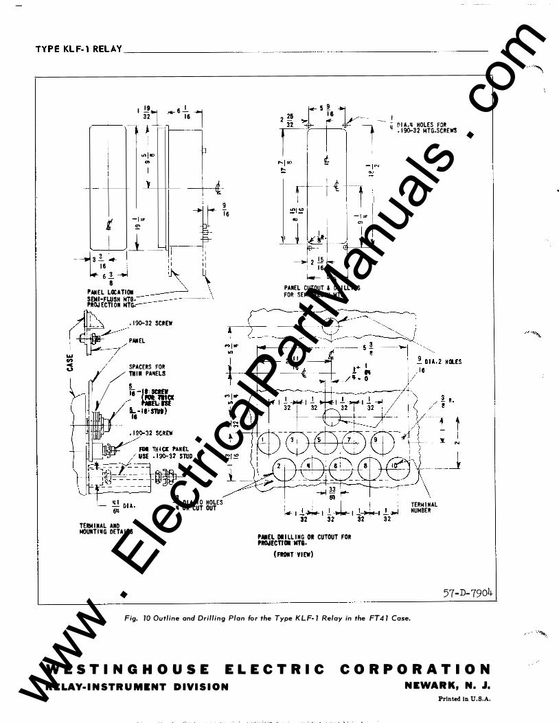
TYPEKLF-l RELAY ________________________________________________________ __
I _.!!1 I-<-6
_!_ 1 32 I I &
ll � tt
---H t �:T
t6 l 9
w "'
? I l_ -=- 'r-- : � --y� I I I , I 1 6 I I I I I 6 _! -.I �_j
PAII EL L�ATIOII � SEMI-FLUSH NTG. P�OJ ECTI ON MTG.
I l_ _ . 190-32 SCIIEW
� PAIIEL
� SPAC£RS FOR / TH i ll PAIIELS
� I �-=.,, I r L -la· sm) I II
TERM I IIAL AIID MOUIITI!IG DETA I LS
_.!_ Dl A. I 0 HOLES 1J OR CUT OUT
2 2& �- S �6 i _ _ I n-4 _. v -t - � D I A.IJ HOLES FOR �-I
. 190-32 14TG.SCREWS
t I � --tt ����w_! II - I :T .., I "' ,
--i �-·1 - j l 1 � � � -i 2 .!.l1 1-- J I 1 6 1--- s I 8
PANEL CUTOUT & DR I LL I NG FOR SEMI FLUSH MTG.
PAIIEL DI I LL I NG 01 CUTOUT FOR PIIOoiECTfOII NT&. (FIOIIT VIEW)
TERiol i HAL HUiolBER
57-D-7904
Fig. 10 Outline and Drilling Plan for the Type K L F· 1 Relay in the FT4 1 Case.
W E S TI N G H O U S E ELECTRIC CORPORATION RELAY·INSTRUMINT DIVISION NEWARK, N. J.
Printed In U.S.A. www . El
ectric
alPar
tMan
uals
. com