
INSTALLATION, OPERATION & MAINTENANCE MANUALlexairinc.com/mta/manuals/MTA_FB6-20_A.pdf · customer...
30
MTA_FB6-20_A.doc INSTALLATION, OPERATION & MAINTENANCE MANUAL ® MECHANICAL GRIP, AIR RELEASED CHUCK 2025 Mercer Road, Lexington, Kentucky 40511 859-255-5001 • 800-445-1196 • Fax 859-255-6656 www.lexairinc.com
Transcript of INSTALLATION, OPERATION & MAINTENANCE MANUALlexairinc.com/mta/manuals/MTA_FB6-20_A.pdf · customer...

MTA_FB6-20_A.doc
INSTALLATION, OPERATION &MAINTENANCE MANUAL
®
MECHANICAL GRIP, AIR RELEASED CHUCK
2025 Mercer Road, Lexington, Kentucky 40511859-255-5001 • 800-445-1196 • Fax 859-255-6656
www.lexairinc.com
1
TABLE OF CONTENTS
PART 1 YOUR NEW CHUCK
Introduction 2
Safety Measures 2
Principles of Operation 5
Air Supply and Tool Requirements 6
PART 2 INSTALLATION
Installation Instructions 7
PART 3 OPERATION
Clamping Force 19
Concentricity 20
PART 4 MAINTENANCE
Exploded View of Chuck 21
Chuck Parts List 22
Maintenance Instructions 23
Disassembly of Chuck 25
Trouble Shooting Guide 26

2
INTRODUCTIONTHANK YOU for selecting a Production Dynamics FULL BORE Chuck as your new workholding device. Your chuck as been designed and manufactured to provide you with the finestself-contained, mechanical grip collet chuck available today. Properly installed, maintained andoperated, your chuck will pay for itself quickly and provide you with years of reliable service.
Before attempting to install or operate your FULL BORE Chuck, please read this manual. Inorder to derive the maximum benefit from your chuck and insure that it is properly installed andoperated, all supervisors, operators, and maintenance personnel should be trained by experiencedindividuals familiar with the chuck’s operating characteristics and required safety precautions.
In the event that you have a question with your new FULL BORE Chuck, call our toll freecustomer assistance hot line at 800-445-1196 to speak to a service technician.
SAFETY MEASURES TO BE OBSERVED SAFETY ALERT SYMBOL
This is the industry “Safety Alert Symbol.” This symbol is used to call your attention to items oroperations that could be dangerous to you or other persons using this equipment. Please readthese messages and follow these instructions carefully.
It is essential that you read the instructions and safety regulations before you attempt to assembleor use this unit.
MEANING OF SIGNAL WORDSA safety related message is identified by a safety alert symbol and a signal word to indicate thelevel of risk involved with a particular hazard. Per ANSI standard Z535.41998 the definitions ofthe three signal words are as follows:
DANGER indicates an imminently hazardous situationwhich, if not avoided, will result in death or serious injury.
WARNING indicates a potentially hazardous situation which,if not avoided, will result in death or serious injury.
CAUTION indicates a potentially hazardous situation which,if not avoided, may result in minor or moderate injury.
Before installing or operating your FULL BORE Chuck, please read this manual carefully.Should ANY questions develop that affect the operation of the chuck, please call ProductionDynamics at 800-445-1196 to speak to a service technician.
DO NOT WEAR GLOVES, TIES, JEWELRY, WATCHES,LOOSE OR ILL FITTING CLOTHING. ALSO LONG HAIRSHOULD BE KEPT OUT OF THE WAY TO PREVENTPERSONAL INJURY AND MACHINE DAMAGE.
3
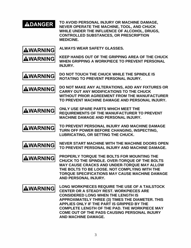
TO AVOID PERSONAL INJURY OR MACHINE DAMAGE,NEVER OPERATE THE MACHINE, TOOL, AND CHUCKWHILE UNDER THE INFLUENCE OF ALCOHOL, DRUGS,CONTROLLED SUBSTANCES, OR PRESCRIPTIONMEDICINE.
ALWAYS WEAR SAFETY GLASSES.
KEEP HANDS OUT OF THE GRIPPING AREA OF THE CHUCKWHEN GRIPPING A WORKPIECE TO PREVENT PERSONALINJURY.
DO NOT TOUCH THE CHUCK WHILE THE SPINDLE ISROTATING TO PREVENT PERSONAL INJURY.
DO NOT MAKE ANY ALTERATIONS, ADD ANY FIXTURES ORCARRY OUT ANY MODIFICATIONS TO THE CHUCKWITHOUT PRIOR AGREEMENT FROM THE MANUFACTURERTO PREVENT MACHINE DAMAGE AND PERSONAL INJURY.
ONLY USE SPARE PARTS WHICH MEET THEREQUIREMENTS OF THE MANUFACTURER TO PREVENTMACHINE DAMAGE AND PERSONAL INJURY.
TO PREVENT PERSONAL INJURY AND MACHINE DAMAGETURN OFF POWER BEFORE CHANGING, INSPECTING,LUBRICATING, OR SETTING THE CHUCK.
NEVER START MACHINE WITH THE MACHINE DOORS OPENTO PREVENT PERSONAL INJURY AND MACHINE DAMAGE.
PROPERLY TORQUE THE BOLTS FOR MOUNTING THECHUCK TO THE SPINDLE. OVER-TORQUE OF THE BOLTSMAY CAUSE CRACKS AND UNDER-TORQUE MAY ALLOWTHE BOLTS TO BE LOOSE. NOT COMPLYING WITH THETORQUE SPECIFICATIONS MAY CAUSE MACHINE DAMAGEAND PERSONAL INJURY.
LONG WORKPIECES REQUIRE THE USE OF A TAILSTOCKCENTER OR A STEADY REST. WORKPIECES ARECONSIDERED LONG WHEN THE LENGTH ISAPPROXIMATELY THREE (3) TIMES THE DIAMETER. THISAPPLIES ONLY IF THE PART IS GRIPPED BY THECOMPLETE LENGTH OF THE PAD. THE WORKPIECE MAYCOME OUT OF THE PADS CAUSING PERSONAL INJURYAND MACHINE DAMAGE.

4
HEAVY CUTS AT HIGH RPM’S CAN CAUSE THEWORKPIECE TO SLIP AND/OR THE WORKPIECE TO COMELOOSE CAUSING MACHINE DAMAGE AND PERSONALINJURY.DO NOT MODIFY THE CHUCK. ANY MODIFICATION MAYCAUSE THE CHUCK TO FAIL CAUSING DAMAGE TO THEMACHINE AND PERSONAL INJURY.
NEVER HAMMER THE CHUCK PADS OR WORKPIECE TOPREVENT MACHINE DAMAGE AND PERSONAL INJURY.
AFTER ANY COLLISION THE COLLET AND THE CHUCKMUST BE REMOVED AND CHECKED FOR ANY CRACKS,IMBALANCE, OR DAMAGE. THE CHUCK MUST NOT BEUSED UNLESS CERTIFIED BY A PERSON WITH PROPERCREDENTIALS TO PREVENT PERSONAL INJURY ANDMACHINE DAMAGE.
REPLACE DAMAGED BOLTS AFTER A COLLISION. BOLTSHOLDING THE FACEPLATE TO THE CHUCK BODY AND/ORUSED TO MOUNT THE CHUCK MUST BE REPLACED WITHBOLTS APPROVED BY THE MANUFACTURER TO PREVENTMACHINE DAMAGE AND PERSONAL INJURY.
WHEN OPERATING PRODUCTION EQUIPMENT OF ANYKIND, GENERAL SHOP SAFETY MEASURES SHOULDALWAYS BE OBSERVED. FOLLOWING THE OPERATINGINSTRUCTIONS, USING GOOD SHOP SAFETY PRACTICESWILL PREVENT MACHINE DAMAGE AND PERSONALINJURY.
BEFORE INSTALLING OR OPERATING YOUR FULL BORECHUCK, PLEASE READ THIS MANUAL CAREFULLY ANDGET ALL OF YOUR QUESTIONS ANSWERED.
WHEN LIFTING THE CHUCK USE THE EYEBOLT AND AHOIST. FOR CHUCKS THAT DO NOT HAVE AN EYEBOLT,USE A LIFTING STRAP OF SUFFICIENT CAPACITY AND AHOIST TO PREVENT PERSONAL INJURY AND MACHINEDAMAGE.
DO NOT OPEN THE CHUCK WHILE THE SPINDLE ISROTATING. THIS WILL CAUSE SEVERE DAMAGE TO THEGLAND AND TO THE BACK OF THE CHUCK. MACHINEDAMAGE AND PERSONAL INJURY CAN RESULT.

5
PRINCIPLES OF OPERATIONThe Production Dynamics FULL BORE Chuck is a self contained, mechanical grip, airrelease front-mounted collet chuck. The chuck does not require an external actuator since theactuator is built into the chuck. Air is used only to OPEN the chuck. Spring force holds theworkpiece while it is being machined. Thus, the part remains clamped, even if air pressure islost. Higher spindle speeds can be used because a collet chuck does not have heavy jaws thatlose grip force as the spindle speed of the machine increases. Clamping force is adjustable bytightening or loosening the collet, using the spanner wrench holes in front of the collet.Removing pairs of springs inside the chuck can also reduce the clamp force. Because the chuckdoes not use a drawtube, more spindle area is available.
The gland and gland housing assembly are used to transmit the air to the chuck. When thespindle is stopped, and the chuck is opened, the air valve allows air into the gland housing,pushing the gland forward against the back of the chuck. The face of the gland seals against thechuck, and allows air pressure to build inside the chuck, moving the piston forward. The rollersdrop back, allowing the pusher to move back and release the collet. The piston compresses thegrip force die-springs. Small return die-springs move the pusher back releasing the collet.
When the chuck is closed, the air to the gland housing is vented to atmosphere, the gland retractsfrom the chuck body, and the springs and wedging action of the piston, ramp, rollers and pusherclose the collet on the part.
6
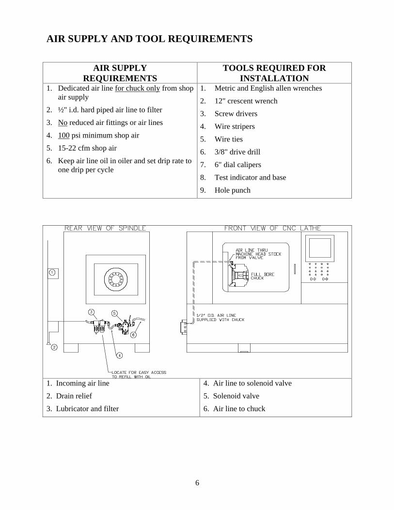
AIR SUPPLY AND TOOL REQUIREMENTS
AIR SUPPLYREQUIREMENTS
TOOLS REQUIRED FORINSTALLATION
1. Dedicated air line for chuck only from shopair supply
2. ½" i.d. hard piped air line to filter
3. No reduced air fittings or air lines
4. 100 psi minimum shop air
5. 15-22 cfm shop air
6. Keep air line oil in oiler and set drip rate toone drip per cycle
1. Metric and English allen wrenches
2. 12" crescent wrench
3. Screw drivers
4. Wire stripers
5. Wire ties
6. 3/8" drive drill
7. 6" dial calipers
8. Test indicator and base
9. Hole punch
1. Incoming air line
2. Drain relief
3. Lubricator and filter
4. Air line to solenoid valve
5. Solenoid valve
6. Air line to chuck
7
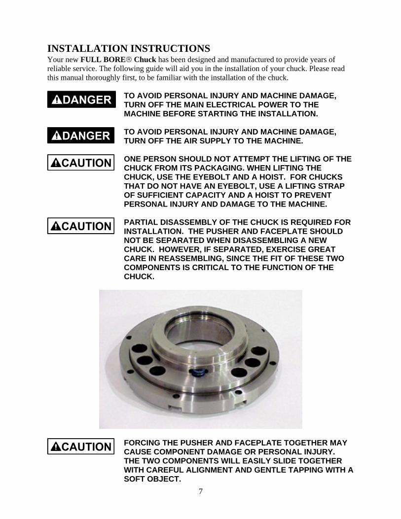
INSTALLATION INSTRUCTIONSYour new FULL BORE Chuck has been designed and manufactured to provide years ofreliable service. The following guide will aid you in the installation of your chuck. Please readthis manual thoroughly first, to be familiar with the installation of the chuck.
TO AVOID PERSONAL INJURY AND MACHINE DAMAGE,TURN OFF THE MAIN ELECTRICAL POWER TO THEMACHINE BEFORE STARTING THE INSTALLATION.
TO AVOID PERSONAL INJURY AND MACHINE DAMAGE,TURN OFF THE AIR SUPPLY TO THE MACHINE.
ONE PERSON SHOULD NOT ATTEMPT THE LIFTING OF THECHUCK FROM ITS PACKAGING. WHEN LIFTING THECHUCK, USE THE EYEBOLT AND A HOIST. FOR CHUCKSTHAT DO NOT HAVE AN EYEBOLT, USE A LIFTING STRAPOF SUFFICIENT CAPACITY AND A HOIST TO PREVENTPERSONAL INJURY AND DAMAGE TO THE MACHINE.
PARTIAL DISASSEMBLY OF THE CHUCK IS REQUIRED FORINSTALLATION. THE PUSHER AND FACEPLATE SHOULDNOT BE SEPARATED WHEN DISASSEMBLING A NEWCHUCK. HOWEVER, IF SEPARATED, EXERCISE GREATCARE IN REASSEMBLING, SINCE THE FIT OF THESE TWOCOMPONENTS IS CRITICAL TO THE FUNCTION OF THECHUCK.
FORCING THE PUSHER AND FACEPLATE TOGETHER MAYCAUSE COMPONENT DAMAGE OR PERSONAL INJURY.THE TWO COMPONENTS WILL EASILY SLIDE TOGETHERWITH CAREFUL ALIGNMENT AND GENTLE TAPPING WITH ASOFT OBJECT.
8
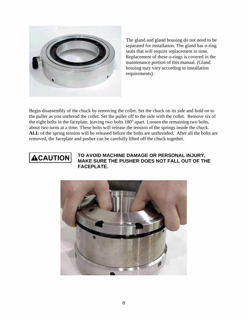
The gland and gland housing do not need to beseparated for installation. The gland has o-ringseals that will require replacement in time.Replacement of these o-rings is covered in themaintenance portion of this manual. (Glandhousing may vary according to installationrequirements).
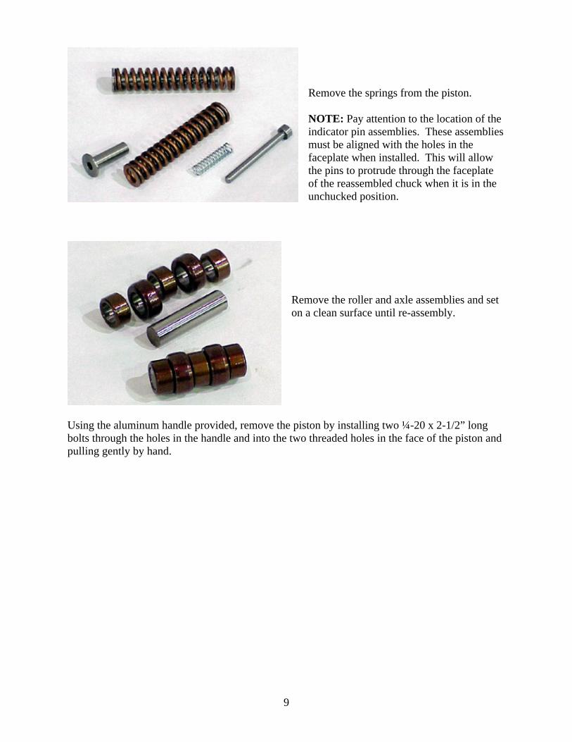
Begin disassembly of the chuck by removing the collet. Set the chuck on its side and hold on tothe puller as you unthread the collet. Set the puller off to the side with the collet. Remove six ofthe eight bolts in the faceplate, leaving two bolts 180 apart. Loosen the remaining two bolts,about two turns at a time. These bolts will release the tension of the springs inside the chuck.ALL of the spring tension will be released before the bolts are unthreaded. After all the bolts areremoved, the faceplate and pusher can be carefully lifted off the chuck together.
TO AVOID MACHINE DAMAGE OR PERSONAL INJURY,MAKE SURE THE PUSHER DOES NOT FALL OUT OF THEFACEPLATE.
9
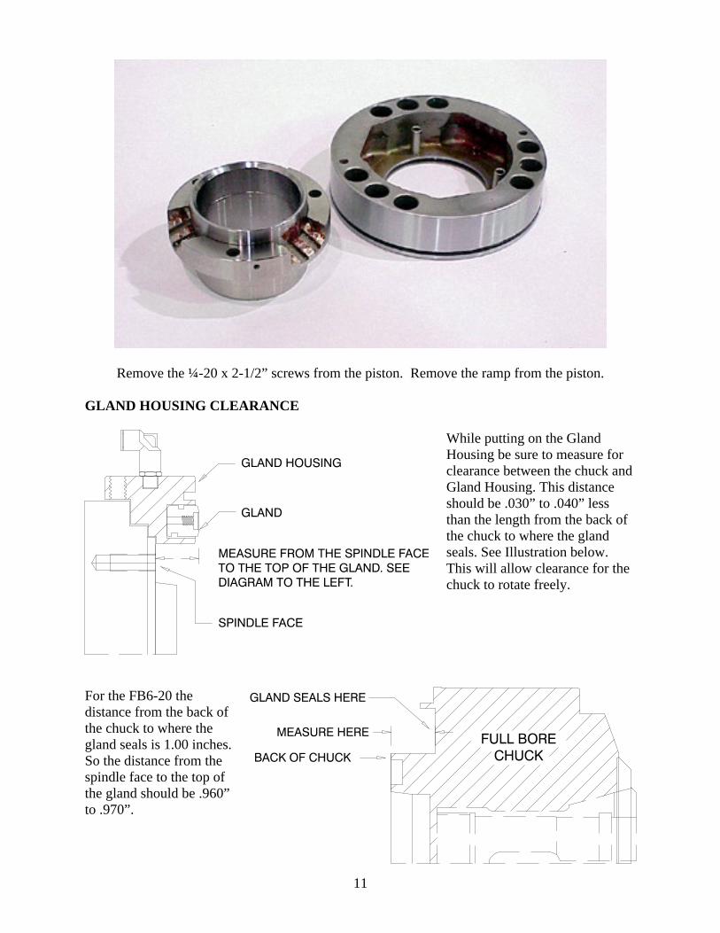
Remove the springs from the piston.
NOTE: Pay attention to the location of theindicator pin assemblies. These assembliesmust be aligned with the holes in thefaceplate when installed. This will allowthe pins to protrude through the faceplateof the reassembled chuck when it is in theunchucked position.
Remove the roller and axle assemblies and seton a clean surface until re-assembly.
Using the aluminum handle provided, remove the piston by installing two ¼-20 x 2-1/2” longbolts through the holes in the handle and into the two threaded holes in the face of the piston andpulling gently by hand.

10
11
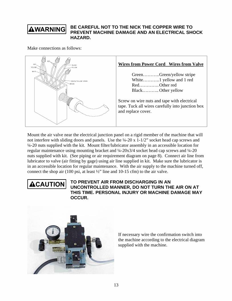
Remove the ¼-20 x 2-1/2” screws from the piston. Remove the ramp from the piston.
GLAND HOUSING CLEARANCE
While putting on the GlandHousing be sure to measure forclearance between the chuck andGland Housing. This distanceshould be .030” to .040” lessthan the length from the back ofthe chuck to where the glandseals. See Illustration below.This will allow clearance for thechuck to rotate freely.
For the FB6-20 thedistance from the back ofthe chuck to where thegland seals is 1.00 inches.So the distance from thespindle face to the top ofthe gland should be .960”to .970”.

12
Mount the gland housing assembly on the spindle bearing housing as shown, with the air fittingin the gland housing on top and the coolant drain at the bottom. Snug the set screws on theoutside diameter of the housing. If there is no provision for an air line, one must be made at alocation where there will be no interference with sliding covers, electrical connections, or thetool eye. Remove the gland housing from the lathe. Use a chassis punch to create a hole that is atleast ½” in diameter. Deburr the hole, and use a grommet in the hole to prevent cutting the airline. Remount the gland housing on the spindle housing, and snug the set screws.
The FULL BORE Chuck Installation Kit contains the necessary air valve, lubricator, filter,fitting, air line tubing, and wire to install the chuck on most machines. The air valve can bemounted in a horizontal or vertical position, but the lubricator/filter must be mounted verticallyat a location where the machine operator can check and service the unit easily.
TURN OFF THE MAIN ELECTRICAL POWER TO THE LATHETO PREVENT DAMAGE TO THE MACHINE AND ELECTRICALSHOCK WHICH COULD CAUSE INJURY OR DEATH.
A QUALIFIED ELECTRICIAN SHOULD PERFORM ALLELECTRICAL WORK.
Loosen the two fillister head screws and remove the junction box cover on the bottom of thevalve near the conduit connection. Pull all five wires into the junction box so that they come outthe bottom of the valve. Strip approximately four inches of the outer rubber jacket off the powercord.
BE CAREFUL NOT TO NICK THE INSULATION ON THEWIRES TO PREVENT MACHINE DAMAGE AND ANELECTRICAL SHOCK HAZARD.
Screw one cord grip (VE0020) into the conduit connection on the valve. Insert the stripped endof the wire through the cord grip and tighten. Make sure the cord is held securely. Strip all ninewires back approximately 3/8 of an inch.
13
BE CAREFUL NOT TO THE NICK THE COPPER WIRE TOPREVENT MACHINE DAMAGE AND AN ELECTRICAL SHOCKHAZARD.
Make connections as follows:
Wires from Power Cord Wires from Valve
Green………..Green/yellow stripeWhite………..1 yellow and 1 redRed…………. Other redBlack……….. Other yellow
Screw on wire nuts and tape with electricaltape. Tuck all wires carefully into junction boxand replace cover.
Mount the air valve near the electrical junction panel on a rigid member of the machine that willnot interfere with sliding doors and panels. Use the ¼-20 x 1-1/2” socket head cap screws and¼-20 nuts supplied with the kit. Mount filter/lubricator assembly in an accessible location forregular maintenance using mounting bracket and ¼-20x3/4 socket head cap screws and ¼-20nuts supplied with kit. (See piping or air requirement diagram on page 8). Connect air line fromlubricator to valve (air fitting by gage) using air line supplied in kit. Make sure the lubricator isin an accessible location for regular maintenance. With the air supply to the machine turned off,connect the shop air (100 psi, at least ½” line and 10-15 cfm) to the air valve.
TO PREVENT AIR FROM DISCHARGING IN ANUNCONTROLLED MANNER, DO NOT TURN THE AIR ON ATTHIS TIME. PERSONAL INJURY OR MACHINE DAMAGE MAYOCCUR.
If necessary wire the confirmation switch intothe machine according to the electrical diagramsupplied with the machine.

14
Look at the manufactures wiring diagram. The chuck control circuits should look something likethose shown below. Make sure the control circuit voltage matches the voltage printed on the airvalve. Most lathes use 24VDC or 100 VAC to control the chuck solenoid.
SK24 U12
U13SK25
S11TYPICAL CHUCK CONTROL CURCUIT
SOL3 CLAMP
SOL4 UNCLAMP
CHUCK
S11
100VAC
24VAC
15
TB1
TB1 TB1AS
SOL3C
TB1
62
24VDC
100VAC
TB1
TB1
CHUCK CLOSE
CHUCK OPENSOL4C
AS
CHANGE TERMINAL CONNECTIONTO MATCH AIR VALVE VOLTAGE
TYPICAL SELECTABLE VOLTAGE CHUCKCONTROL CIRCUIT DIAGRAM
Locate the terminal strip in the electrical cabinet that has the connections for the Chuck Openand Chuck Close solenoids. Locate an area on the electrical cabinet near this terminal strip forthe air valves’ power cord to enter the cabinet. Drill a pilot hole and use a ½ chassis punch topunch out a hole for the cord grip.
TO PREVENT PERSONAL INJURY AND MACHINE DAMAGE,MAKE SURE THE DRILL WILL NOT HIT ANYTHING ON THEINSIDE OF THE CABINET PRIOR TO DRILLING. USE EYEPROTECTION TO KEEP METAL CHIPS FROM INJURINGEYES.
Insert the cord grip into the punched hole and secure in place with the sealing lock nut provided.Push the power cord through the cord grip and tighten, making sure the cord is held firmly.Determine how much wire is needed in the cabinet and cut off any excess. Strip off the rubberjacket as needed.
BE CAREFUL NOT TO NICK THE INSULATION ON THEWIRES TO PREVENT MACHINE DAMAGE AND ANELECTRICAL SHOCK HAZARD.
Strip the insulation off the wires approximately ¼ inch and crimp on the terminals supplied withthe installation kit.
15
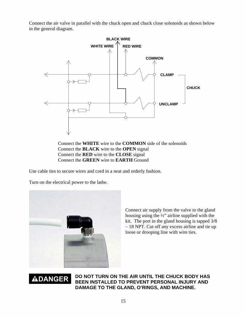
Connect the air valve in parallel with the chuck open and chuck close solenoids as shown belowin the general diagram.
WHITE WIRE
BLACK WIRE
RED WIRE
COMMON
CLAMP
UNCLAMP
CHUCK
Connect the WHITE wire to the COMMON side of the solenoidsConnect the BLACK wire to the OPEN signalConnect the RED wire to the CLOSE signalConnect the GREEN wire to EARTH Ground
Use cable ties to secure wires and cord in a neat and orderly fashion.
Turn on the electrical power to the lathe.
Connect air supply from the valve to the glandhousing using the ½” airline supplied with thekit. The port in the gland housing is tapped 3/8– 18 NPT. Cut off any excess airline and tie uploose or drooping line with wire ties.
DO NOT TURN ON THE AIR UNTIL THE CHUCK BODY HASBEEN INSTALLED TO PREVENT PERSONAL INJURY ANDDAMAGE TO THE GLAND, O’RINGS, AND MACHINE.
16
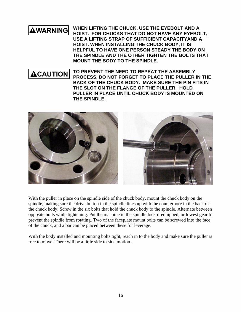
WHEN LIFTING THE CHUCK, USE THE EYEBOLT AND AHOIST. FOR CHUCKS THAT DO NOT HAVE ANY EYEBOLT,USE A LIFTING STRAP OF SUFFICIENT CAPACITYAND AHOIST. WHEN INSTALLING THE CHUCK BODY, IT ISHELPFUL TO HAVE ONE PERSON STEADY THE BODY ONTHE SPINDLE AND THE OTHER TIGHTEN THE BOLTS THATMOUNT THE BODY TO THE SPINDLE.
TO PREVENT THE NEED TO REPEAT THE ASSEMBLYPROCESS, DO NOT FORGET TO PLACE THE PULLER IN THEBACK OF THE CHUCK BODY. MAKE SURE THE PIN FITS INTHE SLOT ON THE FLANGE OF THE PULLER. HOLDPULLER IN PLACE UNTIL CHUCK BODY IS MOUNTED ONTHE SPINDLE.
With the puller in place on the spindle side of the chuck body, mount the chuck body on thespindle, making sure the drive button in the spindle lines up with the counterbore in the back ofthe chuck body. Screw in the six bolts that hold the chuck body to the spindle. Alternate betweenopposite bolts while tightening. Put the machine in the spindle lock if equipped, or lowest gear toprevent the spindle from rotating. Two of the faceplate mount bolts can be screwed into the faceof the chuck, and a bar can be placed between these for leverage.
With the body installed and mounting bolts tight, reach in to the body and make sure the puller isfree to move. There will be a little side to side motion.

17
The gland can now be tested for operation andleaks at this point. Turn on the air supply to thevalve. Use the foot pedal or chuck open/closeswitch to open the chuck. Air will blow out thefeed holes in the inside of the chuck. Thereshould NOT be air leaking from around thebody/gland housing interface. With the air off,and the spindle in high gear, the spindle shouldrotate easily.
TURN OFF AIR SUPPLY AGAIN TO PREVENT MACHINEDAMAGE AND PERSONAL INJURY.
PRODUCTION DYNAMICS RECOMMENDS LUBRIPLATE No.1444 GREASE, PRODUCTION DYNAMICS PART No. VM0012.FAILURE TO USE THIS LUBRICATION MAY CAUSEEXCESSIVE WEAR TO MOVING COMPONENTS AND/ORRESULT IN CHUCK FAILURE.
Apply a light coat of grease to both o-rings onthe piston and to the I.D. of the body. Gentlyslide the piston into the chuck body taking carenot to wedge the piston in the body.
Push it back until it stops against the back ofthe chuck body. Grease the I.D. o-ring in thebody.
Apply a light coat of grease to the rear outsidediameter of the ramp. Insert the rampgently into the piston, until it stops firmlyagainst the shoulder in the body.
18
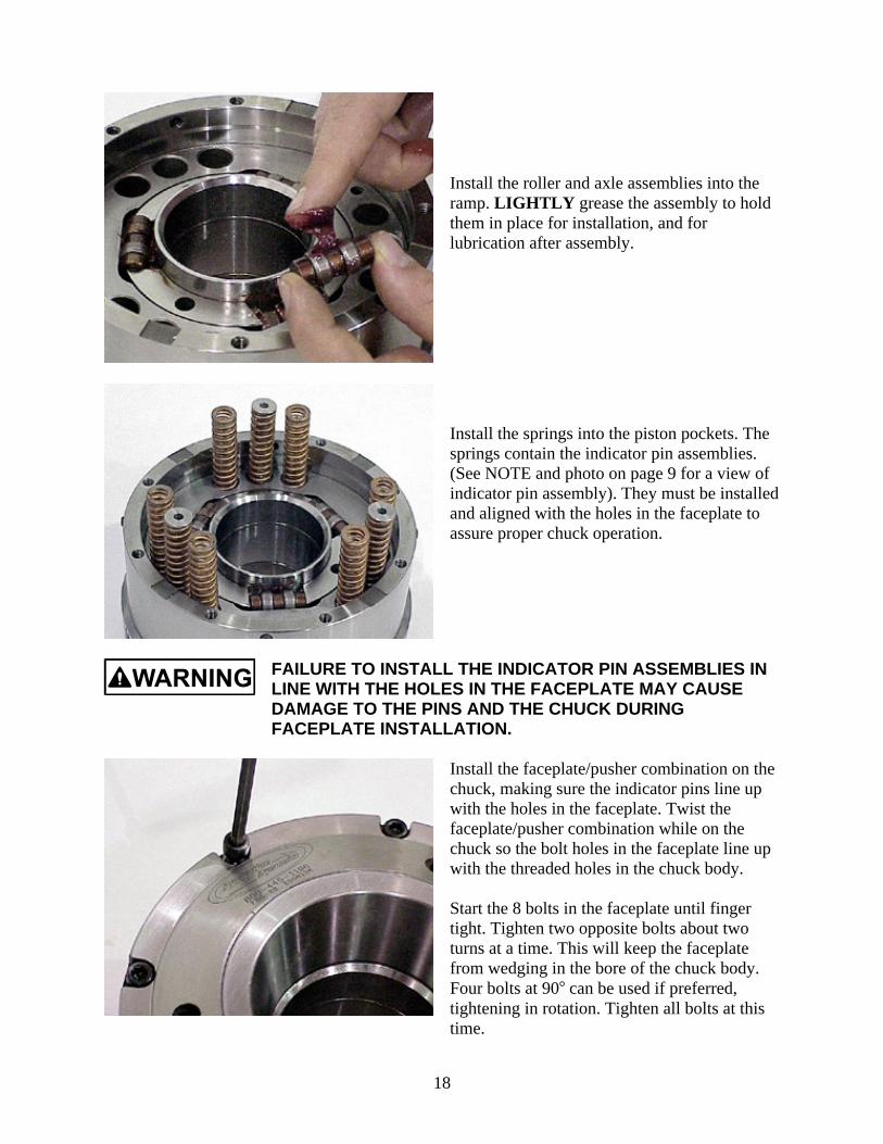
Install the roller and axle assemblies into theramp. LIGHTLY grease the assembly to holdthem in place for installation, and forlubrication after assembly.
Install the springs into the piston pockets. Thesprings contain the indicator pin assemblies.(See NOTE and photo on page 9 for a view ofindicator pin assembly). They must be installedand aligned with the holes in the faceplate toassure proper chuck operation.
FAILURE TO INSTALL THE INDICATOR PIN ASSEMBLIES INLINE WITH THE HOLES IN THE FACEPLATE MAY CAUSEDAMAGE TO THE PINS AND THE CHUCK DURINGFACEPLATE INSTALLATION.
Install the faceplate/pusher combination on thechuck, making sure the indicator pins line upwith the holes in the faceplate. Twist thefaceplate/pusher combination while on thechuck so the bolt holes in the faceplate line upwith the threaded holes in the chuck body.
Start the 8 bolts in the faceplate until fingertight. Tighten two opposite bolts about twoturns at a time. This will keep the faceplatefrom wedging in the bore of the chuck body.Four bolts at 90 can be used if preferred,tightening in rotation. Tighten all bolts at thistime.
19
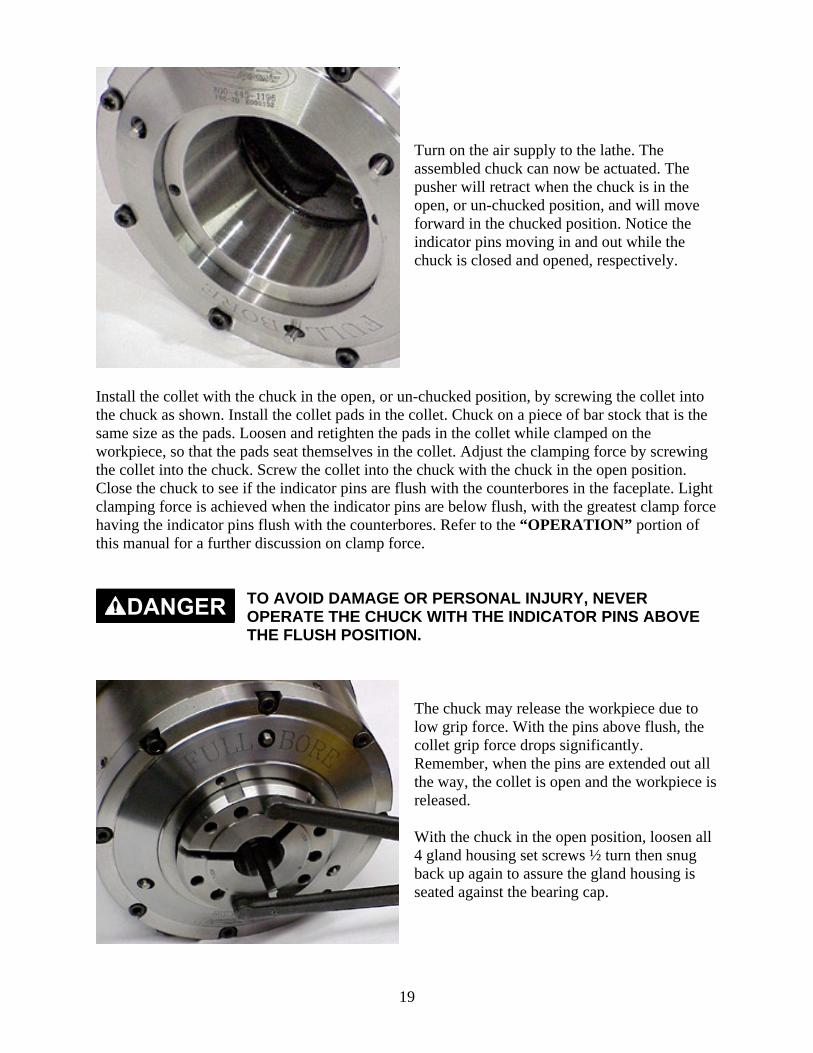
Turn on the air supply to the lathe. Theassembled chuck can now be actuated. Thepusher will retract when the chuck is in theopen, or un-chucked position, and will moveforward in the chucked position. Notice theindicator pins moving in and out while thechuck is closed and opened, respectively.
Install the collet with the chuck in the open, or un-chucked position, by screwing the collet intothe chuck as shown. Install the collet pads in the collet. Chuck on a piece of bar stock that is thesame size as the pads. Loosen and retighten the pads in the collet while clamped on theworkpiece, so that the pads seat themselves in the collet. Adjust the clamping force by screwingthe collet into the chuck. Screw the collet into the chuck with the chuck in the open position.Close the chuck to see if the indicator pins are flush with the counterbores in the faceplate. Lightclamping force is achieved when the indicator pins are below flush, with the greatest clamp forcehaving the indicator pins flush with the counterbores. Refer to the “OPERATION” portion ofthis manual for a further discussion on clamp force.
TO AVOID DAMAGE OR PERSONAL INJURY, NEVEROPERATE THE CHUCK WITH THE INDICATOR PINS ABOVETHE FLUSH POSITION.
The chuck may release the workpiece due tolow grip force. With the pins above flush, thecollet grip force drops significantly.Remember, when the pins are extended out allthe way, the collet is open and the workpiece isreleased.
With the chuck in the open position, loosen all4 gland housing set screws ½ turn then snugback up again to assure the gland housing isseated against the bearing cap.
20
OPERATIONThis portion of the manual is written to enable you to get the most out of your new FULLBORE® Chuck and become familiar with its operations.
TO PREVENT PERSONAL INJURY AND MACHINE DAMAGE,PLEASE CAREFULLY READ AND FOLLOW THESEINSTRUCTIONS BEFORE OPERATING THE CHUCK!
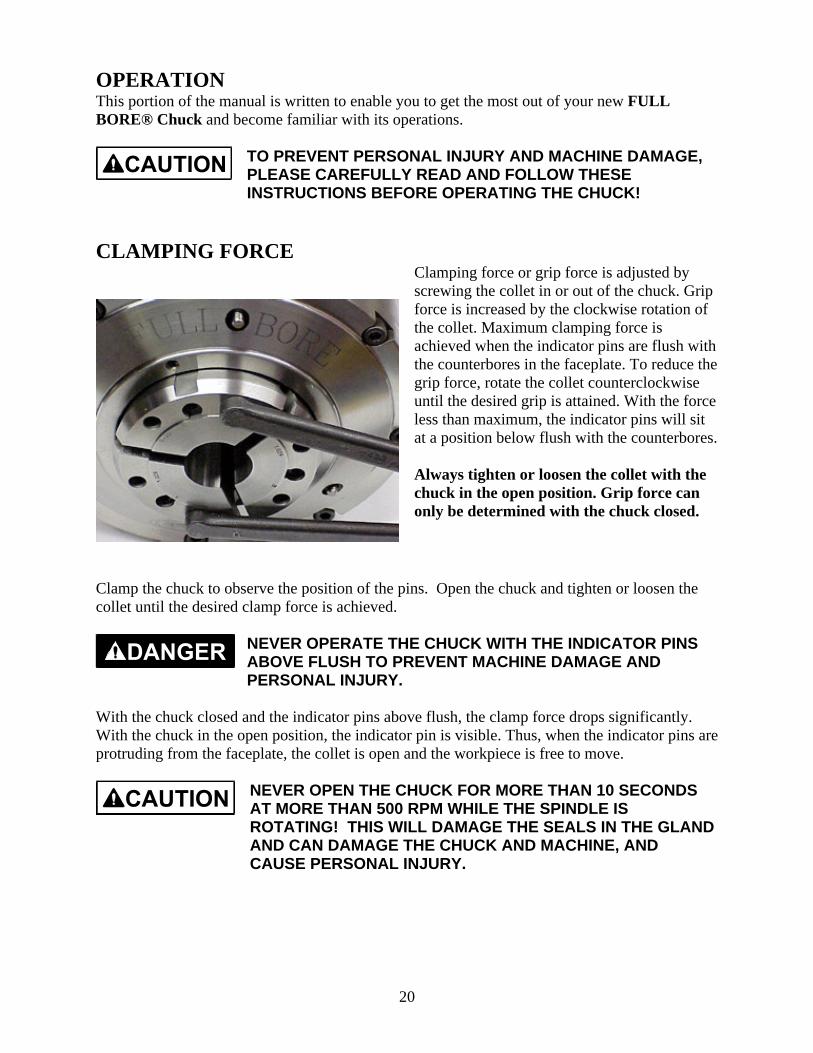
CLAMPING FORCEClamping force or grip force is adjusted byscrewing the collet in or out of the chuck. Gripforce is increased by the clockwise rotation ofthe collet. Maximum clamping force isachieved when the indicator pins are flush withthe counterbores in the faceplate. To reduce thegrip force, rotate the collet counterclockwiseuntil the desired grip is attained. With the forceless than maximum, the indicator pins will sitat a position below flush with the counterbores.
Always tighten or loosen the collet with thechuck in the open position. Grip force canonly be determined with the chuck closed.
Clamp the chuck to observe the position of the pins. Open the chuck and tighten or loosen thecollet until the desired clamp force is achieved.
NEVER OPERATE THE CHUCK WITH THE INDICATOR PINSABOVE FLUSH TO PREVENT MACHINE DAMAGE ANDPERSONAL INJURY.
With the chuck closed and the indicator pins above flush, the clamp force drops significantly.With the chuck in the open position, the indicator pin is visible. Thus, when the indicator pins areprotruding from the faceplate, the collet is open and the workpiece is free to move.
NEVER OPEN THE CHUCK FOR MORE THAN 10 SECONDSAT MORE THAN 500 RPM WHILE THE SPINDLE ISROTATING! THIS WILL DAMAGE THE SEALS IN THE GLANDAND CAN DAMAGE THE CHUCK AND MACHINE, ANDCAUSE PERSONAL INJURY.
21
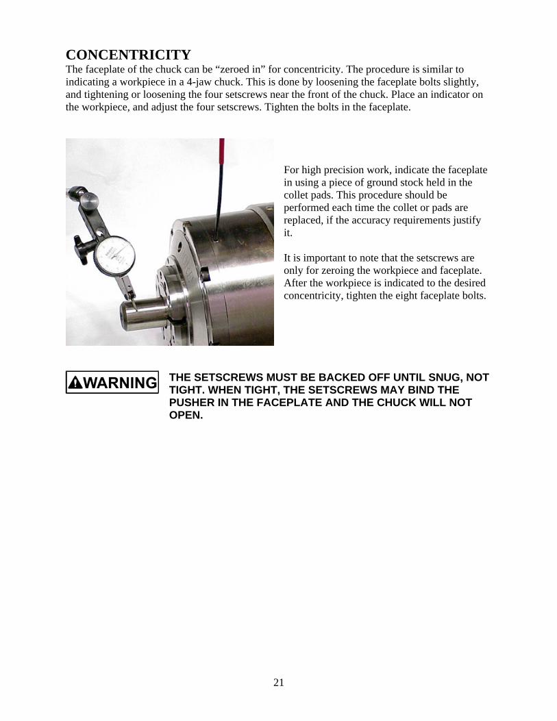
CONCENTRICITYThe faceplate of the chuck can be “zeroed in” for concentricity. The procedure is similar toindicating a workpiece in a 4-jaw chuck. This is done by loosening the faceplate bolts slightly,and tightening or loosening the four setscrews near the front of the chuck. Place an indicator onthe workpiece, and adjust the four setscrews. Tighten the bolts in the faceplate.
For high precision work, indicate the faceplatein using a piece of ground stock held in thecollet pads. This procedure should beperformed each time the collet or pads arereplaced, if the accuracy requirements justifyit.
It is important to note that the setscrews areonly for zeroing the workpiece and faceplate.After the workpiece is indicated to the desiredconcentricity, tighten the eight faceplate bolts.
THE SETSCREWS MUST BE BACKED OFF UNTIL SNUG, NOTTIGHT. WHEN TIGHT, THE SETSCREWS MAY BIND THEPUSHER IN THE FACEPLATE AND THE CHUCK WILL NOTOPEN.

22
Maintenance
23
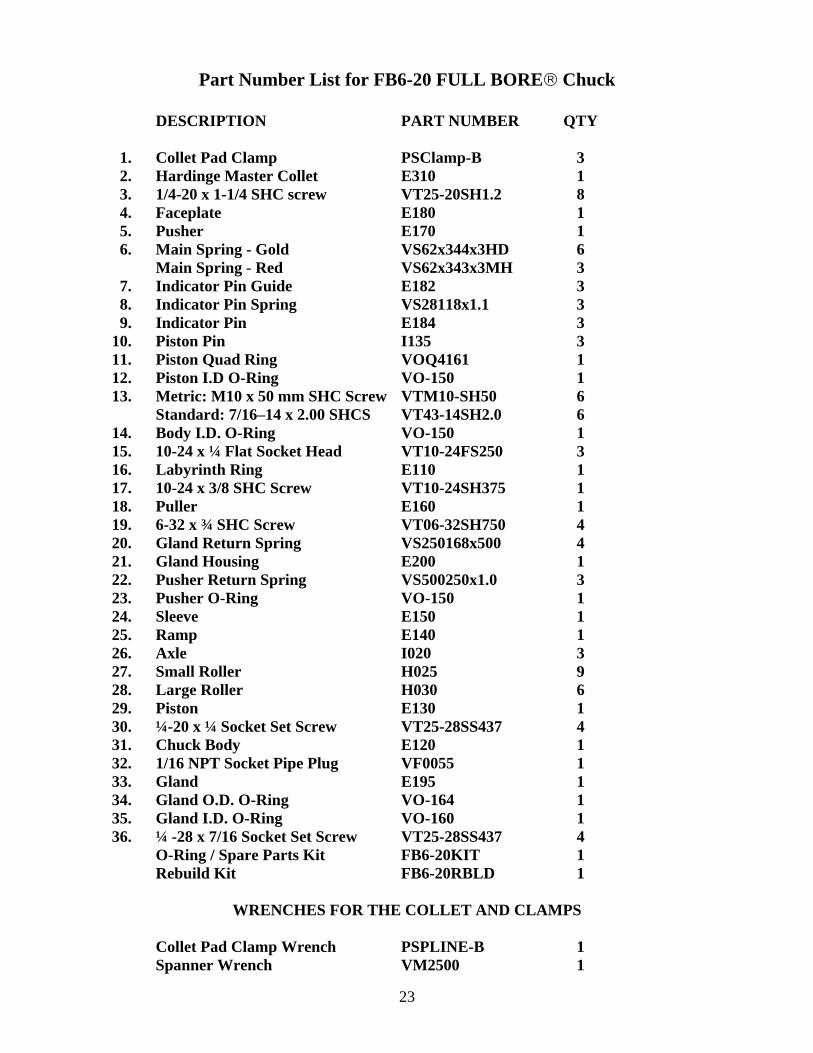
Part Number List for FB6-20 FULL BORE Chuck
DESCRIPTION PART NUMBER QTY
1. Collet Pad Clamp PSClamp-B 32. Hardinge Master Collet E310 13. 1/4-20 x 1-1/4 SHC screw VT25-20SH1.2 84. Faceplate E180 15. Pusher E170 16. Main Spring - Gold VS62x344x3HD 6
Main Spring - Red VS62x343x3MH 37. Indicator Pin Guide E182 38. Indicator Pin Spring VS28118x1.1 39. Indicator Pin E184 3
10. Piston Pin I135 311. Piston Quad Ring VOQ4161 112. Piston I.D O-Ring VO-150 113. Metric: M10 x 50 mm SHC Screw VTM10-SH50 6
Standard: 7/16–14 x 2.00 SHCS VT43-14SH2.0 614. Body I.D. O-Ring VO-150 115. 10-24 x ¼ Flat Socket Head VT10-24FS250 316. Labyrinth Ring E110 117. 10-24 x 3/8 SHC Screw VT10-24SH375 118. Puller E160 119. 6-32 x ¾ SHC Screw VT06-32SH750 420. Gland Return Spring VS250168x500 421. Gland Housing E200 122. Pusher Return Spring VS500250x1.0 323. Pusher O-Ring VO-150 124. Sleeve E150 125. Ramp E140 126. Axle I020 327. Small Roller H025 928. Large Roller H030 629. Piston E130 130. ¼-20 x ¼ Socket Set Screw VT25-28SS437 431. Chuck Body E120 132. 1/16 NPT Socket Pipe Plug VF0055 133. Gland E195 134. Gland O.D. O-Ring VO-164 135. Gland I.D. O-Ring VO-160 136. ¼ -28 x 7/16 Socket Set Screw VT25-28SS437 4
O-Ring / Spare Parts Kit FB6-20KIT 1Rebuild Kit FB6-20RBLD 1
WRENCHES FOR THE COLLET AND CLAMPS
Collet Pad Clamp Wrench PSPLINE-B 1Spanner Wrench VM2500 1

24
MAINTENANCE INSTRUCTIONSIn order to maintain accuracy and minimize wear on internal components of the chuck, periodicservice is required. This procedure should be performed every six (6) months or 50,000 parts,which ever occurs first. Follow the steps below to keep your chuck operating as efficiently aspossible. Refer to the “INSTALLATION” instructions of the manual for further details ifneeded.
TO AVOID PERSONAL INJURY AND MACHINE DAMAGE,WEAR SAFETY GLASSES AND FOLLOW GOOD SHOPSAFETY PRACTICES WHILE PERFORMING ANYMAINTENANCE ON THE CHUCK.
1. Remove the collet from the chuck. Clean chips, coolant and oil from all visible surfaces.
TURN OFF THE MAIN POWER TO THE MACHINE BEFOREBEGINNING THE INSTALLATION PROCEDURE TO AVOIDMACHINE DAMAGE AND PERSONAL INJURY!
2. Remove all but two socket head cap screws opposite each other from the faceplate. Removeremaining screws two turns at a time to prevent the faceplate from wedging in the chuckbody. Refer to the “INSTALLATION” instructions of this manual for more detail.
3. Remove the faceplate and the pusher assembly.
KEEP THIS ASSEMBLY TOGETHER TO PREVENT MACHINEDAMAGE AND PERSONAL INJURY. IF THE TWO PARTS ARESEPARATED, USE GREAT CARE IN THE REASSEMBLY.SLOWLY AND CAREFULLY INSERT THE PUSHER INTO THEFACEPLATE.
DO NOT WEDGE, AS THE PARTS CAN BE PERMANENTLYDAMAGED AND WILL NOT FUNCTION! CLEAN ASNECESSARY FOR REASSEMBLY.
4. Remove the springs, clean, and inspect for any visible damage. Replace any springs that aredamaged with factory authorized parts.
5. Remove the roller and axle assemblies. Inspect for excessive wear and/or cracks on therollers and replace as necessary with factory authorized parts.
6. Remove the ramp and piston together by threading two ¼-20 bolts through the aluminumhandle and into the threaded holes in the piston and pull both out together. Remove the boltsafter the piston and ramp is out of the chuck body.
25
PRODUCTION DYNAMICS RECOMMENDS LUBRIPLATE No.1444 GREASE, PRODUCTION DYNAMICS PART No. VM0012.FAILURE TO USE THIS LUBRICATION MAY CAUSEEXCESSIVE WEAR TO MOVING COMPONENETS AND/ORRESULT IN CHUCK FAILURE.
7. Clean and inspect the inside contour portion of the piston for excessive wear. Replace thepiston if necessary. Replace both o-rings, if necessary, with factory authorized parts, andapply a light coat of grease to each.
8. Remove the chuck body from the spindle by removing the six socket head cap screws. Cleanbody. Clean and inspect the puller that is in the rear counterbore of the body.
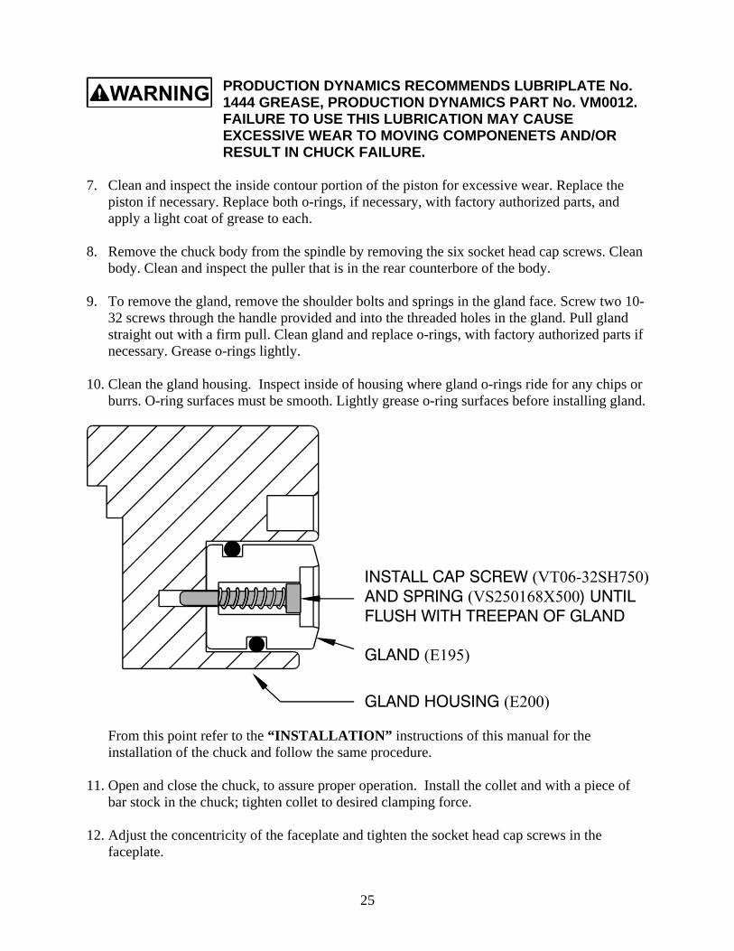
9. To remove the gland, remove the shoulder bolts and springs in the gland face. Screw two 10-32 screws through the handle provided and into the threaded holes in the gland. Pull glandstraight out with a firm pull. Clean gland and replace o-rings, with factory authorized parts ifnecessary. Grease o-rings lightly.
10. Clean the gland housing. Inspect inside of housing where gland o-rings ride for any chips orburrs. O-ring surfaces must be smooth. Lightly grease o-ring surfaces before installing gland.
From this point refer to the “INSTALLATION” instructions of this manual for theinstallation of the chuck and follow the same procedure.
11. Open and close the chuck, to assure proper operation. Install the collet and with a piece ofbar stock in the chuck; tighten collet to desired clamping force.
12. Adjust the concentricity of the faceplate and tighten the socket head cap screws in thefaceplate.

26
PROCEDURE TO DISASSEMBLE THE CHUCK WITH THECOLLET GRIPPED ON THE WORKPIECE
1. TURN AIR OFF TO MACHINE! To prevent damage to the machine and/or personalinjury.
2. Remove two of the faceplate bolts that are opposite each other. Install bolts that are 3/8”longer into these holes. Remove the remaining faceplate bolts, per the procedure in the frontpart of this manual. Begin loosening the two remaining longer bolts. Alternate between thetwo until all spring tension is removed. The longer bolts prevent the faceplate from comingoff under spring tension.
3. Remove the faceplate. The pusher and collet will remain on the chuck.
4. Remove the springs and indicator pins from the piston.
5. With a soft blow hammer, GENTLY begin tapping the pusher back. This should push therollers back into the piston, which will allow the collet to open.
6. Remove workpiece. Remove collet, being careful not to drop the pusher when the collet iscompletely removed.
7. Remove the ramp, rollers, and piston, as described earlier in the manual.
8. Remove the chuck body.
9. Replace O-rings as needed and perform maintenance on the gland and gland housing.
10. Reassemble the chuck
TO PREVENT PERSONAL INJURY AND MACHINE DAMAGE,BE CAREFUL WHEN INSTALLING THE PUSHER IN THEFACEPLATE. GREASE BOTH ITEMS BEFORE INSTALLINGTHE PUSHER IN THE FACEPLATE.
TO PREVENT MACHINE DAMAGE AND PERSONAL INJURY,BE CAREFUL TO USE THE SAME LENGTH BOLTS WHENREINSTALLING THE FACEPLATE.
11. Install collet. Set concentricity. Set grip force.

27
TROUBLE SHOOTING GUIDEThe following procedures should be performed should the chuck not function properly. If thefollowing procedures fail to take care of the problem with the chuck, please call ProductionDynamics at 800-445-1196 to answer your questions.
IN ALL CASES, UNLESS OTHERWISE SPECIFIED, TURN AIRAND ELECTRICAL POWER OFF TO THE MACHINE UNTIL RE-ASSEMBLY IS COMPLETE, TO PREVENT DAMAGE TOMACHINE AND/OR PERSONAL INJURY.
SYMPTOM CAUSE SOLUTION
Chuck not opening,Indicator pins notmoving
Air supply ½” I.D. air line must be capable of supplying 100psi air while flowing a sufficient volume of 20CFM.
Chuck not opening,indicator pins notmoving, air leakbetween chuck andgland housing.
Gland leaking due tocut-o-ring in gland.
Remove chuck from spindle and remove glandfrom housing.
Gland sealing faceworn out.
Replace o-ring and/or gland. Reassemble Chuckand test. Refer to maintenance portion of thismanual for this procedure.
Chuck not opening,air leaking fromindicator pin holes.
Cut o-ring on piston Remove collet, faceplate, springs, rollers, ramp,and piston. Replace o.d. o-ring and/or i.d. o-ring.
Chuck not opening,indicator pinsmoving.
Chips inside chuck,preventing chuckfrom opening.
Disassemble the chuck. Clean, grease lightly,and reassemble.
Pusher stuck tocollet
With chuck in open position, gently tap on pusheruntil pusher moves back. Grease collet andpusher tapers.
Rollers in chuck notrolling back to allowpusher to releasecollet.
Remove collet, faceplate, springs and rollers.Clean and inspect rollers. Apply a small amountof grease to roller assemblies, and reassemble.
Concentricity setscrews to tight.
Back off set screws to snug after faceplate capscrews are tight
Check indicator pintravel.
Low air pressure.

28
SYMPTOM CAUSE SOLUTION
Chuck not opening,indicator pins notmoving.
Broken rollers. Remove collet, faceplate, springs and rollers.Replace all rollers, grease each assembly lightly,and reassemble the chuck.
Stock being pushedback into chuck.
Improperly adjustedcollet.
Readjust clamp force. In chucked position,indicator pins should be flush with counterboresin faceplate.
Check grip forcesprings.
Replace broken Springs.
Smooth pads Try serrated pads.
Stock being crushedby collet.
Improperly adjustedcollet.
Reduce clamp force on workpiece. Indicator pinswill sit less than flush with faceplate. Clamp forcecan also be reduced by removing three mainsprings (Item 6 in Parts List) 120 apart fromeach other. Reassemble the chuck and adjust theclamping force. Always leave a minimum of sixsprings at 120 , three of these having theindicator pin assemblies.
Chuck is getting hot Chuck body rubbingGland Housing
Adjust set screws on the gland housing to centerhousing on the bearing cap.

MTA_FB6-20_A.doc
2025 Mercer Road, Lexington, Kentucky 40511859-255-5001 • 800-445-1196 • Fax 859-255-6656
www.lexairinc.com


![MTA - Unopomp · TM01 8522 0300 MTA 3 MTA 4 L[mm] 35 45 TM01 8657 0600 TM01 8658 0600 TM01 9076 1000 10 L 10 125 45 Min. 20 mm General data MTA. 6 Technical data MTA 3 MTA 4 ... 105](https://static.fdocuments.in/doc/165x107/5be789d309d3f246788ca2ff/mta-tm01-8522-0300-mta-3-mta-4-lmm-35-45-tm01-8657-0600-tm01-8658-0600-tm01.jpg)