Installation, Operation and Troubleshooting Instructions ... · 1 All units are performance tested...
34
Installation, Operation and Troubleshooting Instructions Manual Part No.: P6924700 Rev: 03 Print Date: xx/xx/xx 607 Industrial Way, Eatontown, NJ 07724 Phone: (800) 526- 2807 Fax: (732) 544-0735 Website: www.adamatic.com For Panera Roll-In Model: AP-51 Adamatic Modular Proofers
Transcript of Installation, Operation and Troubleshooting Instructions ... · 1 All units are performance tested...

Installation, Operation and Troubleshooting Instructions
Manual Part No.: P6924700Rev: 03
Print Date: xx/xx/xx
6 0 7 I n d u s t r i a l W a y, E a t o n t o w n , N J 0 7 7 2 4Phone: (800) 526- 2807 Fax: (732) 544-0735 Website: www.adamatic.com
For Panera Roll-In Model: AP-51Adamatic Modular Proofers
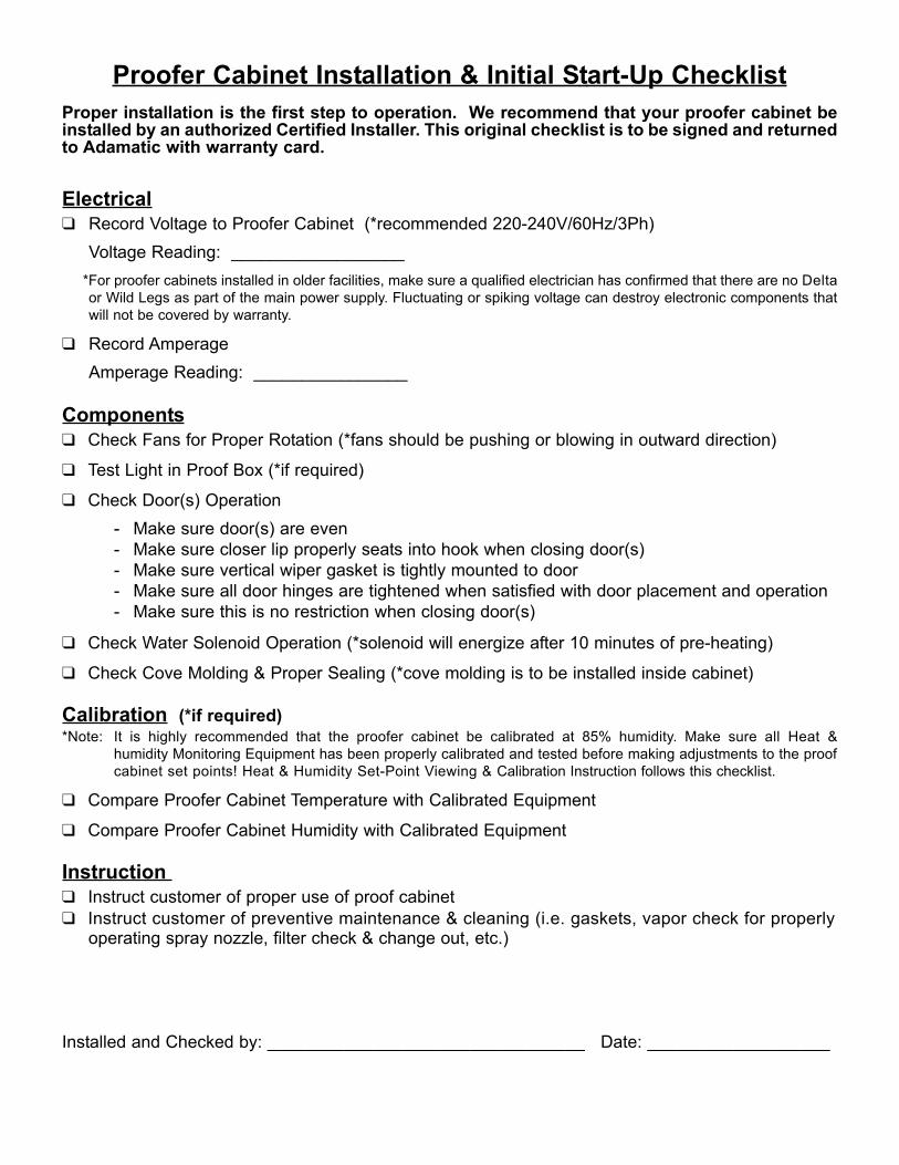
Proofer Cabinet Installation & Initial Start-Up ChecklistProper installation is the first step to operation. We recommend that your proofer cabinet beinstalled by an authorized Certified Installer. This original checklist is to be signed and returnedto Adamatic with warranty card.
Electrical❑ Record Voltage to Proofer Cabinet (*recommended 220-240V/60Hz/3Ph)
Voltage Reading: __________________*For proofer cabinets installed in older facilities, make sure a qualified electrician has confirmed that there are no Delta or Wild Legs as part of the main power supply. Fluctuating or spiking voltage can destroy electronic components thatwill not be covered by warranty.
❑ Record AmperageAmperage Reading: ________________
Components❑ Check Fans for Proper Rotation (*fans should be pushing or blowing in outward direction)
❑ Test Light in Proof Box (*if required)
❑ Check Door(s) Operation - Make sure door(s) are even- Make sure closer lip properly seats into hook when closing door(s)- Make sure vertical wiper gasket is tightly mounted to door- Make sure all door hinges are tightened when satisfied with door placement and operation- Make sure this is no restriction when closing door(s)
❑ Check Water Solenoid Operation (*solenoid will energize after 10 minutes of pre-heating)
❑ Check Cove Molding & Proper Sealing (*cove molding is to be installed inside cabinet)
Calibration (*if required) *Note: It is highly recommended that the proofer cabinet be calibrated at 85% humidity. Make sure all Heat &
humidity Monitoring Equipment has been properly calibrated and tested before making adjustments to the proof cabinet set points! Heat & Humidity Set-Point Viewing & Calibration Instruction follows this checklist.
❑ Compare Proofer Cabinet Temperature with Calibrated Equipment
❑ Compare Proofer Cabinet Humidity with Calibrated Equipment
Instruction ❑ Instruct customer of proper use of proof cabinet ❑ Instruct customer of preventive maintenance & cleaning (i.e. gaskets, vapor check for properly
operating spray nozzle, filter check & change out, etc.)
Installed and Checked by: _________________________________ Date: ___________________

1
All units are performance tested and thoroughly inspected prior to shipment. Upon receipt, examinethe exterior of the shipment packaging for any signs of rough handling. If the cabinet is damaged, itshould be noted on the delivery slip or bill of lading and signed. A claim must be filed immediatelyagainst the carrier indicating the extent and estimated cost of damage incurred.
Proper installation is the first step to operation. We recommend that your proofer be installedby an authorized Certified Installer. An installation checklist is located at the front of manualand must be checked off and signed by installer of choice. The original checklist is to bereturned with warranty card.Consider the following when selecting a location for your proofer:1. Clearance - There must be a minimum clearance of 24” (inches) between the top of the proofer
and the ceiling.
2. Floor Load - The floor on which the cabinet will rest must be free of vibration and suitably strongenough to support the combined weights of the cabinet plus the maximum product load.
*Note: All pictures show the protective vinyl coat on parts described in this instruction document. Make sure all vinyl protective coating is removed before installation. Same method of installation applies to Floorless Proof Boxes with Wall Base Angles only.
Tools Needed: Drill with ¼" (inch) Masonry Bit, Tubes of Silicon, Dynabolt Anchors, Screw Driver, & Trowel
1. Find location to assemble proof cabinet. Before assembly, make sure designated floor area and neighboring wall space is level, clean and free of any obstruction.
2. If supplied, place Stainless Steel Floor on appointed floor space and mark along the edges. (*Note: Same method of installation applies to Floorless Proof Boxes with Wall Base Angles only!)
3. Remove Stainless Steel Floor and apply beads of Floor Adhesive along the bottom while properly spreading with Trowel. Make sure the bead is continuous around the edge of Stainless Steel Floor.
4. Seat Stainless Steel Floor over designated floor space and lightly walk on the Floor. Put still weight on the Stainless Steel Floor so that Adhesive will keep in required contact with Floor beneath (i.e. weights, boxes with weight, etc).
5. Place Wall Base Angles around the edge of Stainless Steel Floor. Make sure that holes located at ends of the Wall Base Angles align over the holes in Stainless Steel Floor.
6. Drill Floor Holes through the Wall Base Angles with a 1/4" diameter drill bit for placement of Concrete Floor Anchors.
●● Mark drill bit at 1-1/2" (inches) from the end. Drill until mark is aligned with the top of the Stainless Steel Floor. Do not drill beyond the mark on the drill bit!
●● Clear concrete dust from holes. (*Note: all debris from drilling must be removed before installation or Anchors will not work!)
●● If proof cabinet is mounted on stone or ceramic tile, extend holes and Anchors into concrete substrate.
FLOOR & WALL BASE ANGLE INSTALLATION
INSTALLATION GUIDELINES
RECEIVING SHIPMENT

7. Install Anchors in the holes of Wall Base Angles and set in place.
Tools Needed : Allen Wrench (*supplied with accessories)
All Proofer Cabinet Panels are joined together by Cam-Locks. Panel sections lock together from insidethe Proofer Cabinet to provide accurate tight joining. Always align top edges and inner face of Panelsas you lock them together.
*Note: From inside Proofer Cabinet, all Cams turn clockwise with exception of inner left hand side of Header that turns counter-clockwise. All Male Cam direction of turn is marked on required panels.
3/4” Wide Foam Tape has been provided for Proof Cabinet Panel sealing. Foam Tape should beplaced over Foam Insulation of all Panel Edges with Male Cams. See Figure 1.
Once Foam Tape has been applied to Panel, cut Slit at all Male Cam locations. See Figure 2.
*Note: Only one strip of Foam Tape should be placed in between Panels. This will guarantee proper Seal and Cam Locking.
Figure 1 Figure 2
CAM-LOCKING PANELS
APPLYING FOAM TAPE
2
Wall Base Angles Optional Floor with Wall Base Angles Assembled *Note: Floor shown with vinyl for clarity.
Remove before assembling!
Floor Anchor Placed atend after checking Corner.
Illustrations show cam-lock panel mechanism frominside the proofer cabinet.

3
Item Part No. Part Description Qty1 P7900101 10”x 82” Panel, Front Left with Controller 1
2 & 6 P7907401 30.5”x 82” Panel, Side Left Front/Right Rear 23 & 7 P7907301 30.5”x 82” Panel, Side Left Rear/ Right Front 2
4 P7905301 37” x 82” Panel, Rear Left 15 P7905401 37” x 82” Panel, Rear Right 18 P7900801 4” x 82” Panel, Front Right 19 P7900901 6” x 60” Panel, Header with Light 1
10 P7901001 34” x 74” Panel, Front Roof 111 P7901101 31” x 74” Panel, Rear Roof 112 P7903601 Door Assembly, RH with Horizontal Handle 113 P7903501 Door Assembly, L H with Horizontal Handle 114 P7907501 4-Heater Air Wash Housing Assembly 1
PANEL ASSEMBLY
PANEL ALIGNMENT PINS
A drawing is supplied with all Proofer Cabinets to assure correct placement of Panels. Each Panel isindividually marked with a number to assist with the assembly sequence. An example is shown below.
Silicone has also been provided to fill in Interior and Exterior Seams between Panels after assembly.
*Note: All cams turn clockwise unless label on panel indicates otherwise!
Panel Alignment Pins have been supplied with your Proof Cabinet and are placed on Panel sides withMale Cams only. Pins support easy alignment and allow Male Cams to properly catch into FemaleCams.
Panel Alignment Pin
Hole for Pin
Pin

*Note: All pictures show the protective vinyl coat on parts described in this instruction. Make sure all vinyl protective coating is removed before installing cove molding.
Tools Needed: Screw Gun, Rubbing Alcohol, Paper Towels and Measuring Tape
1. Measure Top and Bottom of Proof Box to check for proper alignment. See Figure 1.
Figure 12. Wipe down Proof Box Interior Wall Base Angles and Exterior Wall Bottom with Rubbing Alcohol.
See Figure 2 & 2a.
Figure 2 Figure 2a3. Cut Cove Molding Strip to desired length and miter at corners where needed. Peel Paper from
Adhesive Strip and apply Cove Molding to Proof Box's Interior Wall Base Angles and Exterior Wall Bottoms. See Figure 3 & 3a.
Figure 3 Figure 3a4. Install #10 Stainless Steel Self-Tapping Screws into Cove Molding, Interior Wall Base Angles and
Exterior Wall Bottoms. Space Screws approximately 1"(inch) up from bottom of Cove Molding, and 8" to 12" (inches) apart while avoiding Wall Seams. See Figure 4.
Figure 45. Repeat process until all Cove Molding is applied completely around the Proof Box's Interior and
Exterior Bottom. 4
APPLYING COVE MOLDING
interior wall base angles
molding with adhesive
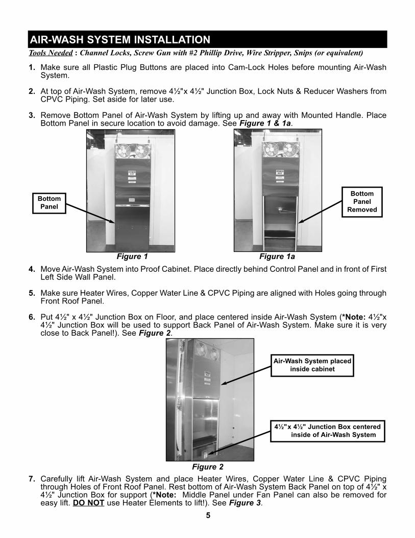
Tools Needed : Channel Locks, Screw Gun with #2 Phillip Drive, Wire Stripper, Snips (or equivalent)
1. Make sure all Plastic Plug Buttons are placed into Cam-Lock Holes before mounting Air-WashSystem.
2. At top of Air-Wash System, remove 4½"x 4½" Junction Box, Lock Nuts & Reducer Washers fromCPVC Piping. Set aside for later use.
3. Remove Bottom Panel of Air-Wash System by lifting up and away with Mounted Handle. PlaceBottom Panel in secure location to avoid damage. See Figure 1 & 1a.
Figure 1 Figure 1a4. Move Air-Wash System into Proof Cabinet. Place directly behind Control Panel and in front of First
Left Side Wall Panel.
5. Make sure Heater Wires, Copper Water Line & CPVC Piping are aligned with Holes going throughFront Roof Panel.
6. Put 4½" x 4½" Junction Box on Floor, and place centered inside Air-Wash System (*Note: 4½"x4½" Junction Box will be used to support Back Panel of Air-Wash System. Make sure it is veryclose to Back Panel!). See Figure 2.
Figure 27. Carefully lift Air-Wash System and place Heater Wires, Copper Water Line & CPVC Piping
through Holes of Front Roof Panel. Rest bottom of Air-Wash System Back Panel on top of 4½" x4½" Junction Box for support (*Note: Middle Panel under Fan Panel can also be removed foreasy lift. DO NOT use Heater Elements to lift!). See Figure 3.
AIR-WASH SYSTEM INSTALLATION
5
BottomPanel
BottomPanel
Removed
Air-Wash System placedinside cabinet
4½"x 4½" Junction Box centeredinside of Air-Wash System

Figure 38. At top of cabinet and left side of Front Roof Panel, place Reducing Washer & Lock Nut over both
CPVC Pipes. Use Channel Locks (or equivalent tool) to tighten until snug. See Figures 4, 4a & 4b.
Figure 4 Figure 4a Figure 4b9. Starting at top of Proof Cabinet, feed Heat/Humidity Sensor Cable Plug through Copper Water Line
CPVC Piping. (*Note: Can use Finger or 5" Flat Head Screwdriver to feed Cable through ifneeded.) See Figures 5 & 5a.
Figure 5 Figure 5a10.After Heat/Humidity Sensor Cable Plug is placed through CPVC Pipe, feed Plug through 3/4" Hole
located at Upper Right Side of Air-Wash System. (*Note: Picture below shows Air-Wash Systemnot mounted to Proof Cabinet for visual purposes.) See Figure 6.
Figure 6
Air-Wash System lift
ReducingWasher &Lock Nutapplied to
CPVC
4½"x 4½" Junction Box placed under Back Panel of
Air-Wash System
Heat/Humidity SensorCable Plug fed into
CPVC Piping
Cable fed through UpperRight Side ¾" Hole or
Air-Wash System
6

11. Take ¾" Heyco Bushing from Accessory Kit and cut at one side with Snips (or equivalent). PlaceHeat/Humidity Sensor Cable Plug into ¾" Heyco Bushing, and fit ¾" Heyco Bushing to ¾" Hole atUpper Right Side of Air-Wash System. See Figures 7 & 7a.
Figure 7 Figure 7a12.Apply Putty in and around Heater Wire & Copper Water Line CPVC Piping. See Figures 8 & 8a.
Figure 8 Figure 8a13.Remove 4"x 4" Junction Box from bottom of Air-Wash System Back Panel. Take out 1 5/16” Knock
Out from one side of 4"x 4" Junction Box. See Figure 9.
Figure 914.Feed Heater Wires and CPVC Pipe through 1 5/16” Knock Out of 4" x 4" Junction Box. 15.Place Lock Nut inside 4" x 4" Junction Box and onto CPVC Threads. Tighten until snug with
Channel Locks (or equivalent tool). See Figure 10 & 10a.
Figure 10 Figure 10a
Cable fed through ¾" Heyco Bushing
¾" Heyco Bushingfitted flush to
Air-Wash System
Putty placed in andaround CPVC Piping
Removal of 1 5/16” Knock Out
Tightening Lock NutPlacing Lock Nut
inside Junction Box
7

16.Secure bottom of Air-Wash System by placing three (3) #10 Stainless Steel Self-Drilling Screws.See Figure 11.
Figure 1117.To complete Air-Wash System installation, apply Bottom Panel by reversing Step #3.
Tools Needed : Phillips Head Screwdriver & Adjustable Wrench 1. Locate Sensor and Klixon Mounting Holes above the Air-Wash System Panel Fans. See Figure 1.
Figure 12. Mount Klixon to Air-Wash System Panel. Make sure Metal Disc side of Klixon has contact with Air-
Wash Panel. See Figure 2.
Figure 2
SENSOR / KLIXON ASSEMBLY & INSTALLATION
Placing Three #10Self-Drilling Screws
Holes for Heat/Humidity Sensor Bracket
Holes for Mounting Klixon
Klixon shown correctlymounted to
Air-Wash Panel
8

9
3. Mount Sensor Bracket to side of Air-Wash System Panel. See Figure 3.
Figure 34. Place and secure Sensor to Sensor Bracket with Screws and Lock Washer Nuts. See Figure 4 &
4a.
Figure 4 Figure 4a5. Connect Sensor Wires to Klixon, and Heat/Humidty Sensor Cable Plug into Sensor Port. See
Figure 5. (*Note: Refer to page 7 and Figure 7 for Heat/Humidity Sensor Cable Plug)
Figure 56. The Sensor and Klixon Assembly is now complete.
Sensor Bracket Mountedto Air-Wash Panel
Sensor Port
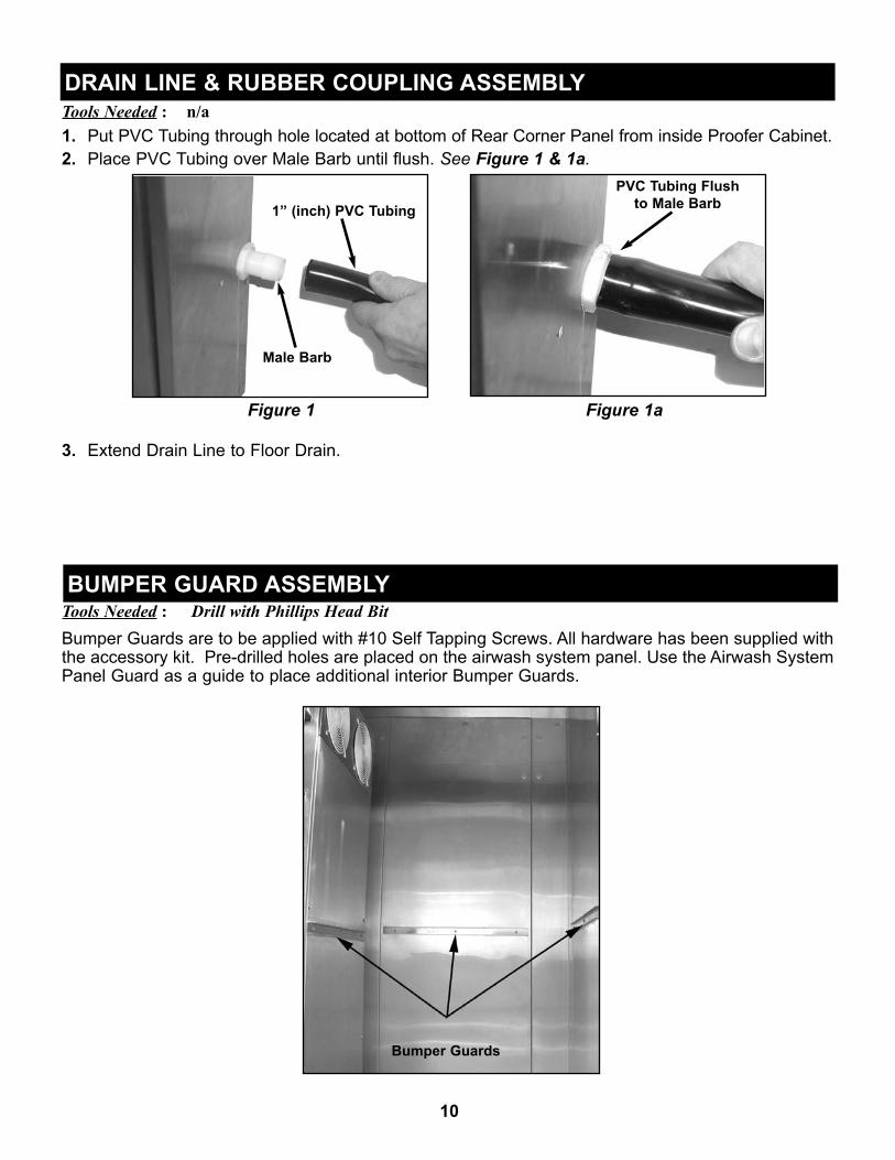
Tools Needed : n/a1. Put PVC Tubing through hole located at bottom of Rear Corner Panel from inside Proofer Cabinet. 2. Place PVC Tubing over Male Barb until flush. See Figure 1 & 1a.
Figure 1 Figure 1a
3. Extend Drain Line to Floor Drain.
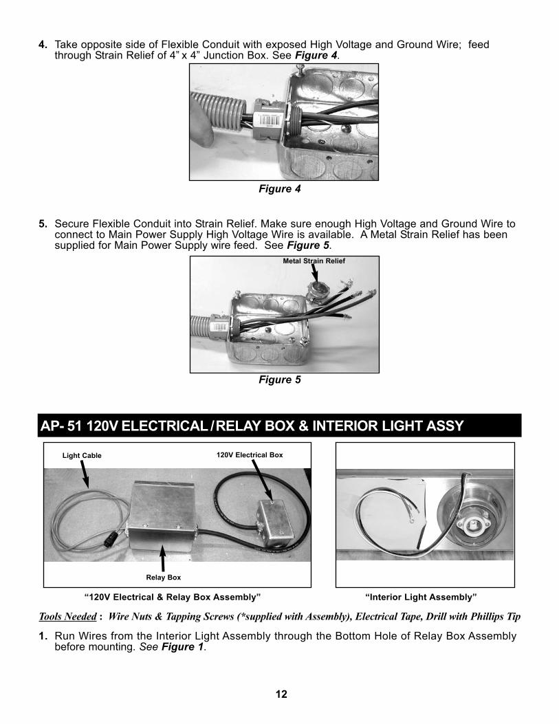
Tools Needed : Drill with Phillips Head Bit Bumper Guards are to be applied with #10 Self Tapping Screws. All hardware has been supplied withthe accessory kit. Pre-drilled holes are placed on the airwash system panel. Use the Airwash SystemPanel Guard as a guide to place additional interior Bumper Guards.
10
DRAIN LINE & RUBBER COUPLING ASSEMBLY
Male Barb
1” (inch) PVC Tubing
BUMPER GUARD ASSEMBLY
Bumper Guards
PVC Tubing Flushto Male Barb

Tools Needed : Drill with Phillips Head Bit
1. Mount 4” x 4” Junction Box at upper right side of Proof Box with supplied Tapping Screws. ApplyStrain Relief with Lock Nut to side of Junction Box closest to Power Module. Refer to “TOPVIEW” on page 18 for approximate placement. See Figure 1.
Figure 1
2. Take Power Module High Voltage Wires with Ground and put through Flexible Conduit. SeeFigure 2.
Figure 2
3. Secure Flexible Conduit into Power Module Strain Relief. See Figure 3 & 3a.
Figure 3 Figure 3a
HIGH VOLTAGE BOX ASSEMBLY
4” x 4”Junction Box
Lock Nut
FlexibleConduit
High Voltage Wires& Ground
Power ModuleStrain Relief
Flexible Conduit
Secured Conduit
Plastic StrainRelief
11
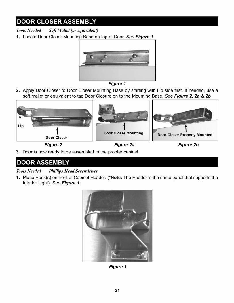
4. Take opposite side of Flexible Conduit with exposed High Voltage and Ground Wire; feedthrough Strain Relief of 4” x 4” Junction Box. See Figure 4.
Figure 4
5. Secure Flexible Conduit into Strain Relief. Make sure enough High Voltage and Ground Wire toconnect to Main Power Supply High Voltage Wire is available. A Metal Strain Relief has beensupplied for Main Power Supply wire feed. See Figure 5.
Figure 5
“120V Electrical & Relay Box Assembly” “Interior Light Assembly”
Tools Needed : Wire Nuts & Tapping Screws (*supplied with Assembly), Electrical Tape, Drill with Phillips Tip
1. Run Wires from the Interior Light Assembly through the Bottom Hole of Relay Box Assembly before mounting. See Figure 1.
AP- 51 120V ELECTRICAL /RELAY BOX & INTERIOR LIGHT ASSY
Light Cable 120V Electrical Box
Relay Box
Metal Strain Relief
12

Figure 12. Mount 120V Relay & Electrical Box in designated locations and secure with supplied #10 Screws.
Make sure Relay Box Bushing is placed into the Hole for Interior Light Wire run. Refer to page 18“Proofer Top View” and see Figures 2 & 2a below.
Figure 2 Figure 2a3. Wire the Interior Light, 120V Electrical/Relay Box, and Light Cable according to the Wiring
Diagram. Make sure all Green Wires (Grounds) are properly secured. Ensure that White 14 Gauge Wires are connected with supplied Wire Nut. See Figures 3, 3a & 3b with comments.
Figure 3“Secure Ground Wires”
Figure 3a“Connect 14 GA Black Wire with
Insulated Push On Terminal To OpenRelay Terminal”
Figure 3b“Connect (2) 14 GA White Wires
Together Using Supplied WireNut”
13

4. Place Light Cable coming from Relay Box into desginated area on Power Module. See Figure 4.
Figure 4
5. 120V/60Hz/1Ph Electrical Supply should be ran into the 120V Electrical Box by a qualifiedelectrician in accordance with local electrical codes. Figure 5.
Figure 5
6. Seal Hole between bottom of Relay Box and Roof Panel with Silicone. See Figure 6.
Figure 6
14

7. Place Covers on Relay and Electrical Box after all wiring has been completed. See Figures 7 & 7a.
Figure 7 Figure 7a
Place Light Bulb and Globe once wiring of the Interior Light is complete.
Tools Needed : Drill with Phillips Tip
4 x 4 Junction Box
1. Feed Air Wash System Fan and Heater Wires through Top Left Front Corner of Roof Panel. SeeFigure 1.
Figure 1
AIR WASH SYSTEM 4 x 4 JUNCTION BOX, FAN MOTORS, HEATERS
Left Rear Knock Out
Fan & HeaterWires
INTERIOR LIGHT BULB & GLOBE
15

2. Remove left rear Button Knock Out on 4” x 4” Junction Box as shown. Install Bushing and mountJunction Box using supplied screws. See Figure 2.
Figure 2
Air Wash Heater Connections3. Remove Right Side Front Knock Out on Junction Box.
4. Install Straight Strain Relief on Black Supply Cable.
5. Insert Black Supply Cable and Straight Strain Relief through Knock Out. Install Lock Nut and tighten. See Figure 3.
Figure 3
6. Connect Heater Lead “L1” 10 Gauge Wire to Black 10 Gauge Wire using supplied Wire Nut.
7. Connect Heater Lead “L2” 10 Gauge Wire to Red 10 Gauge Wire using Supplied Wire Nut.
16
Knock Out
Strain Relief

8. Connect Heater Lead “L3” 10 Gauge Wire to Black 10 Gauge Wire using supplied Wire Nut.
9. Connect Heater Green Grounding Lead to 10 Gauge Green Wire using supplied Green Wire Nut.
Air Wash Fan Motor Connections10. Remove Right Side Front Knock Out on Junction Box.
11. Install Straight Strain Relief on Gray Fan Cable.
12. Insert Cable and Strain Relief into Knock Out. Install Lock Nut and tighten.
13. Connect Fan Lead Black #14 Gauge Wire to Black #20 Gauge Wire using Supplied Wire Nut.
14. Connect Fan Lead Red #14 Gauge Wire to Red #20 Gauge Wire using supplied Wire Nut.
15. Connect Fan Lead Grounding Green #14 Gauge Wire to Grounding Green #20 Gauge Wire usingsupplied Wire Nut.
16. Carefully inspect each Wire Nut connect for proper installation. See Figure 4.
Figure 4
17. Seal Hole for Air Wash Wiring with Silicone. See Figure 5.
Figure 5
18. Carefully place Wires inside of Junction Box and install Cover. See Figure 6 & 6a.
Figure 6 Figure 6a17

“Solenoid & Water Line Assembly”
Tools Needed : Drill with Phillips Tip1. Plug end of Solenoid Valve Cable into designated area on Power Module. See Figures 1 & 1a.
Figure 1 Figure 1a2. Feed Water Line Extension Assembly Union Fitting through Heyco Bushing on second Roof
Panel. The Union Fitting will line up with Flare Nut on Air Wash System for proper connection. Refer to Panera Top View on page 18. See Figures 2 & 2a.
Figure 2 Figure 2a3. After connecting Union Fitting to Air Wash System, get Solenoid Valve Assembly and connect
Water Line Extension Flare Nut. Mount Solenoid Valve Assembly to Roof Panel by placing TappingScrews. See Figures 3 & 3a.
Figure 3 Figure 3a
SOLENOID & WATER LINE EXTENSION ASSEMBLY
18
Solenoid ValveCable
Solenoid ValveCable

19
4. Take Female End of Solenoid Valve Cable and plug onto Solenoid Valve. Secure Female End bytightening Screw with Flat Head Screwdriver. See Figures 4 & 4a.
Figure 4 Figure 4a5. After all Proof Box assembly is complete, connect Water Supply Line to Solenoid Assembly. Make
sure that Ball Valve is in “ON” position before putting Proof Box into operation. See Figure 5.
Figure 5
Ball Valve
Water Line Connection Fitting
PANERA AP-51 PROOFER TOP VIEW
Power Module
Main ConnectionUtility Box
Main Power Supply(208-240/60/3)
Electrical Box(120/60/1)
Relay Box(120V)
Water Solenoid

2
Tools Needed : Drill with Phillips Head Bit Assemble the Facade on top of the proofer cabinet in the sequence shown below. Use the 5/8” SelfTapping Screws that have been supplied.
Tools Needed : Phillips Head Screwdriver If Proof Box does not power up and Main Power Supply is good, shut off Main Power and turn PowerModule Disconnect Switch to “OFF” position. Remove 8 Screws at Plate beside Disconnect Switchand check Circuit Breaker and Fuses. Reverse steps to properly resupply power to Proof Box.
20
TOP FACADE ASSEMBLY
POWER MODULE CABLE CONFIGURATION
POWER MODULE CIRCUIT BREAKER & FUSES
Control PanelCable
Fan MotorCable Solenoid
ValveCable Main
PowerSupply
Main PowerSupply To4x4 Box
Heat/HumiditySensor Cable
Proof CycleIndicator Light
Cable
Fuses
Disconnect
Removing PlateScrews
CircuitBreakerSwitch
1
2
3
5
Item Part No. Part Description1 P6026500 Grill, Upper Front2 P6052700 Panel, LH/RH Upper End3 P6026100 Upper Rear Gusset, RH4 P6900906 Outer Roof Cover Panel (1ea)5 P6026201 Upper Rear Gusset, LH
4
21
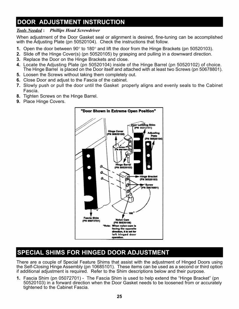
Tools Needed : Soft Mallet (or equivalent)1. Locate Door Closer Mounting Base on top of Door. See Figure 1.
Figure 12. Apply Door Closer to Door Closer Mounting Base by starting with Lip side first. If needed, use a
soft mallet or equivalent to tap Door Closure on to the Mounting Base. See Figure 2, 2a & 2b
Figure 2 Figure 2a Figure 2b3. Door is now ready to be assembled to the proofer cabinet.
Tools Needed : Phillips Head Screwdriver1. Place Hook(s) on front of Cabinet Header. (*Note: The Header is the same panel that supports the
Interior Light) See Figure 1.
Figure 1
Door CloserDoor Closer Mounting Door Closer Properly Mounted
Lip
DOOR CLOSER ASSEMBLY
DOOR ASSEMBLY

2. Locate three (3) Door Hinge Bases on Door Jamb. See Figure 2.
Figure 2
3. Carefully take Door(s) and insert all three (3) Hinge Barrels inside Nylon Cam of Hinge Base. HaveDoor(s) open at 90° or more when placing Door(s) on to the Door Jamb. See Figure 3 & 3a.(Note: If door does not easily drop into nylon cams, remove middle hinge barrel. After top and bottom hinge barrelshave been seated into nylon cams, install middle hinge barrel)
Figure 3 Figure 3a
Hinge Barrel
Hinge Base
Nylon Cam
22
Hinge Base & Cam

4. After placement of Door(s), check Closer Lip to make sure it properly seats into Hook when closingDoor(s). Put Hinge Covers on all three (3) Hinges to complete assembly. See Figure 4, Figure 4a& 4b
Figure 4 Figure 4b
Put on Door Handle(s) with 1/4 x 20 Hex Bolt & Lock Washers and Interior Guard(s) with #10 Self-Tapping Screws. (*Note: All Doors are shipped with Mounting Holes for easy assembly!)
Hinge
Hinge Cover
Closer Lip
Hook
23
Closer Lip
Figure 4a
DOOR HANDLE AND GUARD ASSEMBLY
GuardDoor Handle

Tools Needed : n/a
1. Discontinue power to cabinet and lift Bottom Front Panel up and away from Air-Wash System. SeeFigure 1, 1a & 1b.
Figure 1 Figure 1a Figure 1b2. Remove Filter and wash in Soap & Water. (*Note: If Filter must be replaced, use one of two
spares that came with Proof Cabinet, or order P/N P7014700). See Figure 2 & 2a.
Figure 2 Figure 2a
3. With Filter removed, clean Drain Pan with clean Sponge or Rag. See Figure 2a.
4. Re-install Filter between Receiving Pockets of Drain Assembly (*Note: Filter closes off entireopening). See Figure 2 & 2a.
5. Re-install Bottom Front Panel of Air-Wash System by reversing Step #1.
AIR-WASH SYSTEM FILTER & DRAIN PAN CLEANING
24
Filter Drain Pan
Tools Needed : Phillips Head ScrewdriverWhen adjustment of the Door Gasket seal or alignment is desired, fine-tuning can be accomplishedwith the Adjusting Plate (pn 50520104). Check the instructions that follow.1. Open the door between 90° to 180° and lift the door from the Hinge Brackets (pn 50520103).2. Slide off the Hinge Cover(s) (pn 50520105) by grasping and pulling in a downward direction.3. Replace the Door on the Hinge Brackets and close.4. Locate the Adjusting Plate (pn 50520104) inside of the Hinge Barrel (pn 50520102) of choice.
The Hinge Barrel is placed on the Door itself and attached with at least two Screws (pn 50678801).5. Loosen the Screws without taking them completely out.6. Close Door and adjust to the Fascia of the cabinet.7. Slowly push or pull the door until the Gasket properly aligns and evenly seals to the Cabinet
Fascia.8. Tighten Screws on the Hinge Barrel.9. Place Hinge Covers.
There are a couple of Special Feature Shims that assist with the adjustment of Hinged Doors usingthe Self-Closing Hinge Assembly (pn 10685101). These items can be used as a second or third optionif additional adjustment is required. Refer to the Shim descriptions below and their purpose.1. Fascia Shim (pn 05072701) - The Fascia Shim is used to help extend the “Hinge Bracket” (pn
50520103) in a forward direction when the Door Gasket needs to be loosened from or accurately tightened to the Cabinet Fascia.
DOOR ADJUSTMENT INSTRUCTION
SPECIAL SHIMS FOR HINGED DOOR ADJUSTMENT
25

When using this Shim, build-up the Hinge Bracket by inserting one at a time until the forward extensionsupports an acceptable Gasket Seal to the Cabinet. Hinge Bracket adjustments can be different fromdoor to door. Make sure that the open end of the slot shaped cut -out is always facing towards the Door.
2. Leveling Shim (pn 50538601) - The Leveling Shim is used to raise the Door in and up or downdirection. This part is placed behind the the Hinge Barrel (pn 50520102) with the open ends of thethree slot shaped cut-out’s facing towards the Cabinet. While adjusting the top or bottom Screws per Hinge Barrel, the Door will go in a specific direction. a.) Top Hinge Barrel with Leveling Shim - Adjusts the Door in a downward direction.b.) Bottom Hinge Barrel with Leveling Shim - Adjusts the the Door in an upward direction.
*Note: When inserting and/or adjusting the Leveling Shim, avoid taking the Screws completely out of the Door. Try to make a gap wide enough to slip the Shim in between the Hinge Barrel and the Door, then tighten the Screws until the leveling process of the Door is satisfactory and stable.
RemovingBeginning at one corner, pry gasket loose from the retaining strip. Peel remainder of gasket from thedoor and discard.ReplacingBefore replacing, be sure the gasket and door are at room temperature. If necessary, soak thegasket in warm water to make it more pliable. Align new gasket frame on the door retainer strip.Starting at one corner, press each corner of the gasket into the retainer strip. Once started, thegasket can be easily inserted around the entire perimeter of the door by simply press rolling intoplace.
The Panera AP-51 Proofer Cabinet can hold 6 single racks, or 2 double and 2 Single racks.
After the cabinet has been installed, leveled and cleaned as described, refer to the following checklistprior to start-up.
Check for proper electrical hook-up.Check that cabinet is level.
Check drain line to make sure it is free of kinks and restriction.
Cabinet CleaningAdamatic recommends periodic internal and exterior cleaning as outlined below. Use non-abrasivecleaners that do not contain chlorine and a soft cloth or sponge. Do not use steel wool, scrapers, wirebrushes or other harsh items to clean your proofer.Daily Exterior Cleaning
1. Clean surface with a sponge and cleaning solution. 2. Polish with a soft cloth for stainless steel, wiping with the grain of the metal.3. Once a week wipe with a film cutting agent to maintain shine and stainless steel finish.
INSTALLATION CHECKLIST
PERIODIC MAINTENANCE
26
DOOR GASKET REPLACEMENT
RACK CAPACITY

Weekly Interior Cleaning1. Turn proofer cabinet “OFF”. 2. Remove loose particles from interior floors, walls and ceiling.3. Scrub all interior surfaces with warm detergent solution 100 °F - 120°F (38°C - 39°C) and a
nylon bristled brush. 4. Rinse with clear water and allow to air dry.5. Remove filter and clean. Replace filter if necessary. 6. Turn proofer cabinet “ON”.
All proofers are supplied with a top mounted power module that includes a"disconnect switch". The disconnect switch is the simplest way to cut off andrestore power to the proofer's working components and control board circuitry.Common practice is to always disconnect power from the main powersource!
Start-UpOn top of the cabinet, make certain that the main powermodule is in the “ON” position (*see above) . Press themain power “ON/OFF” button on the control panel and aLED and digital alarm test will take place.After the testing stage is complete, the controller will recallall previous settings. (*Note: if cabinet loses power frommain source, previous settings will still be recalled)At this point, a ten minute pre-heat cycle will begin. Theheat will run at the set temperature for ten minutes prior tothe humidity starting. This allows for the proof box to heatand warm the interior walls alleviating moisture running tothe floor.
How to Set Temperature & HumidityAs long as the proofer cabinet is “ON”, the control systemwill maintain the proofer’s internal temperature andhumidity set points. Temperature and Humidity settings canbe adjusted by using the (up) and (down) keys locatedon the controller next to the corresponding display. The internal temperature set point can be adjusted from40°F to 120°F, and the internal humidity set point from 20%to 95%. To change the displayed temperature fromFahrenheit to Celsius or Celsius to Fahrenheit, press both
(up) and (down) keys at the same time located by the“SET TEMPERATURE” display.
Setting TimerThe controller has the ability to run up to six timerprograms. To set proofing times, press the (up) and
(down) keys next to the “TIME SET” display to choosefrom Rack 1 thru 6. When the correct rack number appears,use the (up) and (down) keys next to the “PROOFERTIME” display to set the amount of time in hours andminutes that you would want the displayed rack to proof.
27
DISCONNECT SWITCH
“Disconnect Switch”
CONTROL PANEL & HOW IT WORKS

To activate the countdown timer, press the start button underneath the proof timer (*when timer isrunning, the colon between hours and minutes will flash). To see the time for each rack, press the
(up) and (down) keys next to “TIME SET” to verify the time left on that numbered rack.When the time has expired for a particular rack, the buzzer will sound, the lights on the display willflash as well as the indicator light at the upper right corner of the proofer box. The rack whose timehas expired will show in the time display LED. Hit the “STOP” button to turn off timer. (*Note: whenpressing the “STOP” button, it will only stop the rack displayed in the “TIME SET” LED. The remainingrack timers will continue to run.)
Viewing Temperature & Humidity Set-PointsTo view Heat & Humidity Set-Points while proof cabinet is in normal "ON" state:(1) Press (up) and (down) keys next to "TIME SET" display window in following sequence:
(2) When in view mode, "SET TEMPERATURE" and "SET HUMIDITY" display windows willrepeatedly flash exact proof cabinet temperature and humidity. (3) To come out of view mode, press
(up) or (down) key next to "TIME SET" display window and proof cabinet will go back to normal"ON" state.
Error CodesShould any error code appear on the display, depress the “MAIN POWER” button on control panel to“OFF”. Wait 5 minutes and turn proofer cabinet back on. Should error code again appear, call forservice.
Shut-DownThe shut-down is initiated by depressing the power key while in the “ON” state. A dry out stage willbegin consisting of a ten minute period where the fans continue to run and the internal temperature isheld at set point. The humidity will be “OFF” during this period to allow the box to dry out. At the endof the ten minute dry out cycle, the box will go into a five minute cool down phase to reduce the heatinside the proofer. At the conclusion of the cool down phase, the box will automatically shut down.
Temperature & Humidity Calibration *Note: It is highly recommended that the proof cabinet be calibrated at 85% humidity. Make sure all Heat & HumidityMonitoring Equipment has been properly calibrated and tested before making adjustments to the proof cabinet set points!
(1) If proof cabinet is not "ON", power-up proof cabinet by pressing "ON / OFF" button located at "MAINPOWER" section of controller. (2) Wait for proof cabinet to complete 7-second diagnostic test. (3) Toenter calibration mode, press (up) and (down) keys located next to "TIME SET" display window infollowing sequence: (4) When in calibration mode, "SET TEMPERATURE" and "SETHUMIDITY" display windows will repeatedly flash exact proof cabinet temperature and humidity. (5) Temperature and humidity set-points can now be adjusted (or calibrated) by using press (up) and
(down) keys located next to "SET TEMPERATURE" and "SET HUMIDITY" display windows. (6) When temperature and humidity adjustments are complete, press (up) or (down) key next to"TIME SET" display window to lock-in settings and take proof cabinet back to normal "ON" state.
Adamatic strives to provide excellent customer service along with quality equipment. To help us betterassist you, a serial number and/or model number must be provided when contacting the technicalservice or parts department. The data plate is located inside the proofer cabinet on back of thecontroller’s corner panel. All serial numbers are recorded and kept indefinitely.Although common replacement parts have been presented throughout this manual, it is best to contactAdamatic to confirm the replacement part of choice.
TECHNICAL SERVICE & REPLACEMENT PARTS
28

29
TROUBLESHOOTING (*Error Message & Probable Cause Table)Caution: This information is for Service Technicians! Disconnect Power Supply Prior to Attempting Any Service!
Heater TimeoutError Code: “ERR 1“
*Sensor calling for heat more than 60
minutes
High Internal Temp. Error Code: “ERR 3“
*Sensor findinginternal cabinet
temperature 15ºF thanset point with no
decrease in internaltemperature for more
than 10 minutes
Keypad Error Error Code: “ERR 5“
*System detected adepressed key when
power is initiallyapplied to the unit
Sensor Comm.Error Code: “ERR 6“
*Sensor Board hasstopped transmittingdata for more than 30
seconds
Thermal Overload Error Code: “ERR 7“
*Sensor finding atripped thermaloverload switch
Sensor Timeout Error Code: “ERR 8“
*Sensor board notsending data 35seconds or more
Most Probable Causes:
1. Proofer Door open
Most Probable Causes:
1. DefectiveTemperature Sensor
Most Probable Causes:
1. Someone is depressing key while power is being applied during start-up
Most Probable Causes:
1. Sensor Cable has been disconnected
Most Probable Causes:
1. Thermal Overload Sensor disconnected
Most Probable Causes:
1. DefectiveSensor Board
2. Heater Power Cable disconnected
2. Defective Power Triac 2. Defective Keypad 2. Defective Sensor Board
2. Defective Thermal Overload Sensor
2. Defective Sensor Cable
3. L3 (Phase-3) Fusetripped or blown
3. DefectiveDisplay Board
3. DefectiveSensor Cable
3. Defective Temperature Sensor
3. Defective Interface Cable
4. Defective Sensor Board
4. DefectiveInterface Cable
4. DefectiveInterface Cable
4. Defective Display Board
5. Defective Interface Cable
5. DefectiveSensor Cable
6. Defective Sensor Cable
7. Defective Safety Relay(s)
8. Defective Power Triac
9. Defective Power Triac Driver

30
COMMON REPLACEMENT PARTS
Item # Part # Description1 P6009700 Fan Motor2 50185001 Fan Blade3 50265802 Fan Guard4 P6099701 Sensor & Klixon Kit5 P6032500 Heater Safety6 P6010401 Spray Nozzle, 80°7 P6010500 Body Spray Adapter8 P6099501 Power Module
Item # Part # Description9 P6099501 Power Module
10 P6099801 Flashing Indicator Lamp11 P6011900 Ball Valve12 P6011700 Water Solenoid13 P6030800 Light Housing14 P6030900 Interior Light Globe15 P6800036 Controller Assembly16 P6049200 Filter, 24” x 16” Foam
Item # Part # Description1 10685101 Hinge Assembly (complete)2 P6009900 Door Closure3 P6020501 Door Handle4 P6009301 Door Gasket, 3-Sided (*not shown)5 P6009502 Wiper Seal,30” Bottom (*not shown)6 P6009602 Wiper Seal,60” Side (*not shown)7 P7903501 Door Assembly, LH Complete 8 P7903601 Door Assembly, RH Complete
Air Wash System
Doors12
3
Item Part No. Description Qty1 P7906301 Fan Panel Assembly 12 P7906401 Electrical Box Assembly 13 P6800004 Heater Box Assembly 14 P7904101 Chassis Assembly 15 P6800023 Front Panel Assembly Lift Off 16 P6053000 Front Panel 17 P7906201 Drain Pan Assembly 18 P6048600 Lower Front Panel 19 P6008801 Heater Bracket 1
10 P6008503 Top Panel 111 P6008902 Bracket, Spray Nozzle 112 P6020601 Carrier Filter 113 P6022500 Heat & Humidity Sensor Bracket 114 P6024101 Bracket, Bumper Guard 115 P6024000 Bumper Guard, Drain 116 P6011301 Hairpin Heater 417 P6800009 Water Line H Feed Assembly 1

31
WIRING DIAGRAM

Adamatic Baking Equipment & Sales607 Industrial Way
Eatontown, NJ 07724 Tel: (800) 526-2807Fax: (732) 544-0735
Web: www.adamatic.com