Installation, Operation, and Maintenance · The Trane®programmable zone sensor (p/n X1379088401)...
32
Programmable Zone Sensor June 2010 BAS-SVX17B-EN Installation, Operation, and Maintenance SAFETY WARNING Only qualified personnel should install and service the equipment. The installation, starting up, and servicing of heating, ventilating, and air-conditioning equipment can be hazardous and requires specific knowledge and training. Improperly installed, adjusted or altered equipment by an unqualified person could result in death or serious injury. When working on the equipment, observe all precautions in the literature and on the tags, stickers, and labels that are attached to the equipment.
-
Upload
hoangtuyen -
Category
Documents
-
view
220 -
download
0
Transcript of Installation, Operation, and Maintenance · The Trane®programmable zone sensor (p/n X1379088401)...

Programmable Zone Sensor
June 2010 BAS-SVX17B-EN
Installation, Operation,
and Maintenance
�SAFETY WARNING
Only qualified personnel should install and service the equipment. The installation, starting up, and servicing of heating, ventilating, and air-conditioning equipment can be hazardous and requires specific knowledge and training. Improperly installed, adjusted or altered equipment by an unqualified person could result in death or serious injury. When working on the equipment, observe all precautions in the literature and on the tags, stickers, and labels that are attached to the equipment.
2 BAS-SVX17B-EN
Copyright
© 2010 Trane All rights reserved
This document and the information in it are the property of Trane and may not be used or reproduced in whole or in part, without the written permission of Trane. Tranereserves the right to revise this publication at any time and to make changes to its content without obligation to notify any person of such revision or change.
Trademarks
Trane and its logo are trademarks of Trane in the United States and other countries. All trademarks referenced in this document are the trademarks of their respective owners.
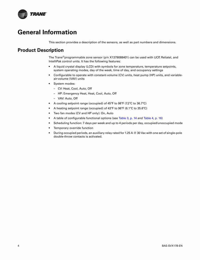
Warnings, Cautions, and Notices
Warnings, cautions, and notices are provided in appropriate places throughout this document:
� WARNING: Indicates a potentially hazardous situation which, if not avoided, could result in death or serious injury.
�CAUTION: Indicates a potentially hazardous situation which, if not avoided, may result in minor or moderate injury. It may also be used to alert against unsafe practices.
NOTICE: Indicates a situation that may result in equipment or property-damage- only accidents.
BAS-SVX17B-EN 3
Table of Contents
General Information . . . . . . . . . . . . . . . . . . . . . . . . . . . . . . . . . . . . . . . . . . . . . . . . . . . . 4
Product Description . . . . . . . . . . . . . . . . . . . . . . . . . . . . . . . . . . . . . . . . . . . . . . . . 4
Dimensions . . . . . . . . . . . . . . . . . . . . . . . . . . . . . . . . . . . . . . . . . . . . . . . . . . . . . . . 5
Pre-Installation . . . . . . . . . . . . . . . . . . . . . . . . . . . . . . . . . . . . . . . . . . . . . . . . . . . . . . . . . 6
Location Considerations . . . . . . . . . . . . . . . . . . . . . . . . . . . . . . . . . . . . . . . . . . . . 6
Height Requirements . . . . . . . . . . . . . . . . . . . . . . . . . . . . . . . . . . . . . . . . . . . . . . . 6
Mounting Surfaces . . . . . . . . . . . . . . . . . . . . . . . . . . . . . . . . . . . . . . . . . . . . . . . . . 6
Wire Length . . . . . . . . . . . . . . . . . . . . . . . . . . . . . . . . . . . . . . . . . . . . . . . . . . . . . . . 7
Installation . . . . . . . . . . . . . . . . . . . . . . . . . . . . . . . . . . . . . . . . . . . . . . . . . . . . . . . . . . . . . 8
Mounting the Back Plate . . . . . . . . . . . . . . . . . . . . . . . . . . . . . . . . . . . . . . . . . . . . 8
Wiring the Sensor . . . . . . . . . . . . . . . . . . . . . . . . . . . . . . . . . . . . . . . . . . . . . . . . . . 9
Replacing the Cover . . . . . . . . . . . . . . . . . . . . . . . . . . . . . . . . . . . . . . . . . . . . . . . 11
Applying Power to the Sensor . . . . . . . . . . . . . . . . . . . . . . . . . . . . . . . . . . . . . . 12
Configuration . . . . . . . . . . . . . . . . . . . . . . . . . . . . . . . . . . . . . . . . . . . . . . . . . . . . . . . . . 13
Operation . . . . . . . . . . . . . . . . . . . . . . . . . . . . . . . . . . . . . . . . . . . . . . . . . . . . . . . . . . . . . 18
Set-up Procedures . . . . . . . . . . . . . . . . . . . . . . . . . . . . . . . . . . . . . . . . . . . . . . . . 18Changing the System Setting . . . . . . . . . . . . . . . . . . . . . . . . . . . . . . . . . . . 18Changing the Fan Setting (CV/HP Configuration only) . . . . . . . . . . . . . . 19Setting the Time Clock and the Day . . . . . . . . . . . . . . . . . . . . . . . . . . . . . 19Scheduling . . . . . . . . . . . . . . . . . . . . . . . . . . . . . . . . . . . . . . . . . . . . . . . . . . 20Scheduling for VAV Occupied Periods . . . . . . . . . . . . . . . . . . . . . . . . . . . 21Temporary Override Set-up (CV/HP only) . . . . . . . . . . . . . . . . . . . . . . . . . 22
Locking or Unlocking the Keypad . . . . . . . . . . . . . . . . . . . . . . . . . . . . . . . . . . . 23
Status Inputs . . . . . . . . . . . . . . . . . . . . . . . . . . . . . . . . . . . . . . . . . . . . . . . . . . . . . 23
Default Operation . . . . . . . . . . . . . . . . . . . . . . . . . . . . . . . . . . . . . . . . . . . . . . . . . 23
Setpoint Only Display . . . . . . . . . . . . . . . . . . . . . . . . . . . . . . . . . . . . . . . . . . . . . 24Weekly Operating Schedule Forms . . . . . . . . . . . . . . . . . . . . . . . . . . . . . . 24
Maintenance and Troubleshooting . . . . . . . . . . . . . . . . . . . . . . . . . . . . . . . . . . . . . . 27
Error Codes . . . . . . . . . . . . . . . . . . . . . . . . . . . . . . . . . . . . . . . . . . . . . . . . . . . . . . 27
Conducting a Self-Test . . . . . . . . . . . . . . . . . . . . . . . . . . . . . . . . . . . . . . . . . . . . . 27
Check Filter Timer . . . . . . . . . . . . . . . . . . . . . . . . . . . . . . . . . . . . . . . . . . . . . . . . . 27
Troubleshooting Table . . . . . . . . . . . . . . . . . . . . . . . . . . . . . . . . . . . . . . . . . . . . 28
Specifications . . . . . . . . . . . . . . . . . . . . . . . . . . . . . . . . . . . . . . . . . . . . . . . . . . . . . . . . . 29
Declaration of CE Conformity . . . . . . . . . . . . . . . . . . . . . . . . . . . . . . . . . . . . . . . . . . . 30Notes: . . . . . . . . . . . . . . . . . . . . . . . . . . . . . . . . . . . . . . . . . . . . . . . . . . . . . . 31
4 BAS-SVX17B-EN
General Information
This section provides a description of the sensors, as well as part numbers and dimensions.
Product Description
The Trane®programmable zone sensor (p/n X1379088401) can be used with UCP, Reliatel, and IntelliPak control units. It has the following features:
• A liquid crystal display (LCD) with symbols for zone temperature, temperature setpoints, system operating modes, day of the week, time of day, and occupancy settings
• Configurable to operate with constant-volume (CV) units, heat pump (HP) units, and variable-air-volume (VAV) units
• System modes:
– CV: Heat, Cool, Auto, Off
– HP: Emergency Heat, Heat, Cool, Auto, Off
– VAV: Auto, Off
• A cooling setpoint range (occupied) of 45ºF to 98ºF (7.2ºC to 36.7ºC)
• A heating setpoint range (occupied) of 43ºF to 96ºF (6.1ºC to 35.6ºC)
• Two fan modes (CV and HP only): On, Auto
• A table of configurable functional options (see Table 3, p. 14 and Table 4, p. 16)
• Scheduling function: 7 days per week and up to 4 periods per day, occupied/unoccupied mode
• Temporary override function
• During occupied periods, an auxiliary relay rated for 1.25 A @ 30 Vac with one set of single-pole double-throw contacts is activated.
BAS-SVX17B-EN 5
General Information
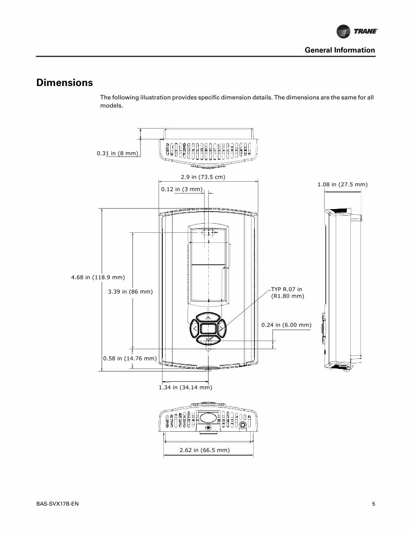
Dimensions
The following illustration provides specific dimension details. The dimensions are the same for all models.
2.9 in (73.5 cm)1.08 in (27.5 mm)
4.68 in (118.9 mm)
1.34 in (34.14 mm)
0.58 in (14.76 mm)
0.31 in (8 mm)
0.12 in (3 mm)
TYP R.07 in (R1.80 mm)
3.39 in (86 mm)
0.24 in (6.00 mm)
2.62 in (66.5 mm)
6 BAS-SVX17B-EN
Pre-Installation
This section provides the following pre-installation information:
• Location considerations
• Height requirements
• Mounting surfaces
• Recommended wire lengths
Location Considerations
Placement of the sensor is critical to proper operation. When selecting a location, avoid the following:
• Areas of direct sunlight
• Areas in the direct airstream of air diffusers
• Exterior walls and other walls that have a temperature differential between the two sides
• Areas that are close to heat sources such as sunlight, appliances, concealed pipes, chimneys, or other heat-generating equipment
• Drafty areas
• Dead spots behind doors, projection screens, or corners
• Walls that are subject to high vibration
• Areas with high humidity
• High traffic areas (to reduce accidental damage or tampering)
Height Requirements
It is recommended that you mount the back plate a maximum distance of 54 inches above the floor. If a parallel approach by a person in a wheelchair is required, reduce the maximum height to 48 inches.
Note: Consult section 4.27.3 of the 2002 ADA (Americans with Disability Act) guideline, and local building codes, for further details regarding wheelchair requirements.
Mounting Surfaces
Using the hardware provided, mount the back plate to a flat surface such as sheetrock or plaster, or an electrical junction box. The sensor must be mounted plumb for accurate temperature control and to ensure proper air movement through the sensor.
• If mounting onto sheetrock or plaster, use the plastic threaded anchors (pre-drilling holes is not usually necessary) and the two M3.5 x 20 mm mounting screws.
• For mounting onto an electrical junction box, use the two 6-32 x 3/4 in. screws.
• If you are replacing a horizontally mounted sensor and need to cover an opening in the wall, use the adapter kit (p/n BAYMTPL103A).
BAS-SVX17B-EN 7
Pre-Installation
Wire Length
Maximum recommended wire lengths for the sensor are given in Table 1:
Table 1. Recommended wire lengths
Wire sizeMaximum recommended wire length from unit controller to sensor
AWG mm2 Meters Feet
22 0.33 0–46 0–150
20 0.50 47–73 151–240
18 0.75 74–117 241–385
16 1.30 118–185 386–610
14 2.00 186–296 611–970
Note: The total resistance of these low voltage wires must not exceed 2.5 Ω/conductor. Any resistance greater than 2.5 Ω may cause the control to malfunction due to an excessive voltage drop.
8 BAS-SVX17B-EN
Installation
This section provides step-by-step installation instructions. Read through the pre-installation information before proceeding with the installation.
Note: Before installing the sensor, ensure that:
• A wire access hole is available at the sensor location
• The wires are accessible through the hole
• The wires are attached to the appropriate unit controller
• There is continuity between the sensor location and the unit controller
• The wires are accurately labeled or identified by color
Mounting the Back Plate
�WARNING
Hazardous voltage!
Disconnect all electric power, including remote disconnects before servicing. Follow proper lockout/tagout procedures to ensure the power cannot be inadvertently energized. Failure to disconnect power before servicing could result in death or serious injury.
NOTICE
Equipment damage!
Applying excessive voltage to the sensor will permanently damage it.
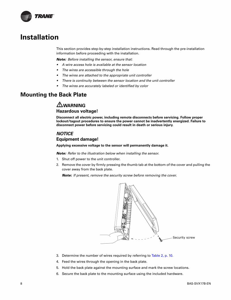
Note: Refer to the illustration below when installing the sensor.
1. Shut off power to the unit controller.
2. Remove the cover by firmly pressing the thumb tab at the bottom of the cover and pulling the cover away from the back plate.
Note: If present, remove the security screw before removing the cover.
3. Determine the number of wires required by referring to Table 2, p. 10.
4. Feed the wires through the opening in the back plate.
5. Hold the back plate against the mounting surface and mark the screw locations.
6. Secure the back plate to the mounting surface using the included hardware.
Security screw
BAS-SVX17B-EN 9
Installation
Wiring the Sensor
�WARNING
Hazardous voltage!
Disconnect all electric power, including remote disconnects before servicing. Follow proper lockout/tagout procedures to ensure the power cannot be inadvertently energized. Failure to disconnect power before servicing could result in death or serious injury.
NOTICE
Equipment damage!
Applying excessive voltage to the sensor will permanently damage it.
To wire the sensor to the unit controller (see guidelines for wire sizes and lengths in Table 1, p. 7.):
1. Ensure that the wires are connected to the appropriate terminals at the unit controller.
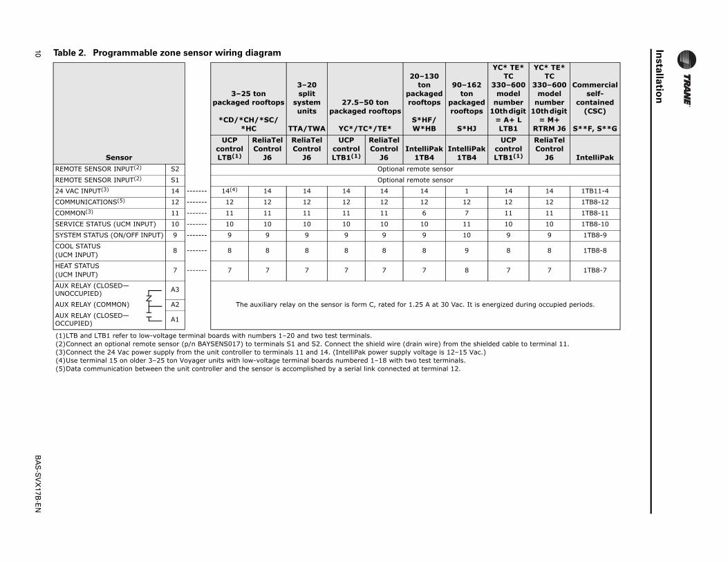
2. Connect the wires to the terminal block (included in the hardware package with the sensor). See Table 2, p. 10 to determine where to terminate wires in the terminal block.
Note: The numbers on the terminal block correspond to the numbers on the terminals of the unit controllers most frequently used with the sensor.
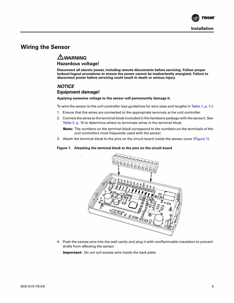
3. Attach the terminal block to the pins on the circuit board inside the sensor cover (Figure 1).
4. Push the excess wire into the wall cavity and plug it with nonflammable insulation to prevent drafts from affecting the sensor.
Important: Do not coil excess wire inside the back plate.
Figure 1. Attaching the terminal block to the pins on the circuit board
10B
AS
-SV
X17B
-EN
Insta
llatio
n
Table 2. Programmable zone sensor wiring diagram
Sensor
3–25 ton packaged rooftops
*CD/*CH/*SC/*HC
3–20 split
system units
TTA/TWA
27.5–50 ton packaged rooftops
YC*/TC*/TE*
20–130 ton
packaged rooftops
S*HF/W*HB
90–162 ton
packaged rooftops
S*HJ
YC* TE* TC
330–600 model
number 10th digit
= A+ L LTB1
YC* TE* TC
330–600 model
number 10th digit
= M+ RTRM J6
Commercial self-
contained (CSC)
S**F, S**G
UCP control LTB(1)
ReliaTel Control
J6
ReliaTel Control
J6
UCP control LTB1(1)
ReliaTel Control
J6IntelliPak
1TB4IntelliPak
1TB4
UCP control LTB1(1)
ReliaTel Control
J6 IntelliPak
REMOTE SENSOR INPUT(2) S2 Optional remote sensor
REMOTE SENSOR INPUT(2) S1 Optional remote sensor
24 VAC INPUT(3) 14 ------- 14(4) 14 14 14 14 14 1 14 14 1TB11-4
COMMUNICATIONS(5) 12 ------- 12 12 12 12 12 12 12 12 12 1TB8-12
COMMON(3) 11 ------- 11 11 11 11 11 6 7 11 11 1TB8-11
SERVICE STATUS (UCM INPUT) 10 ------- 10 10 10 10 10 10 11 10 10 1TB8-10
SYSTEM STATUS (ON/OFF INPUT) 9 ------- 9 9 9 9 9 9 10 9 9 1TB8-9
COOL STATUS(UCM INPUT)
8 ------- 8 8 8 8 8 8 9 8 8 1TB8-8
HEAT STATUS(UCM INPUT)
7 ------- 7 7 7 7 7 7 8 7 7 1TB8-7
AUX RELAY (CLOSED—UNOCCUPIED)
A3
The auxiliary relay on the sensor is form C, rated for 1.25 A at 30 Vac. It is energized during occupied periods.AUX RELAY (COMMON) A2
AUX RELAY (CLOSED—OCCUPIED)
A1
(1)LTB and LTB1 refer to low-voltage terminal boards with numbers 1–20 and two test terminals.(2)Connect an optional remote sensor (p/n BAYSENS017) to terminals S1 and S2. Connect the shield wire (drain wire) from the shielded cable to terminal 11.(3)Connect the 24 Vac power supply from the unit controller to terminals 11 and 14. (IntelliPak power supply voltage is 12–15 Vac.)(4)Use terminal 15 on older 3–25 ton Voyager units with low-voltage terminal boards numbered 1–18 with two test terminals.(5)Data communication between the unit controller and the sensor is accomplished by a serial link connected at terminal 12.
BAS-SVX17B-EN 11
Installation
Replacing the Cover
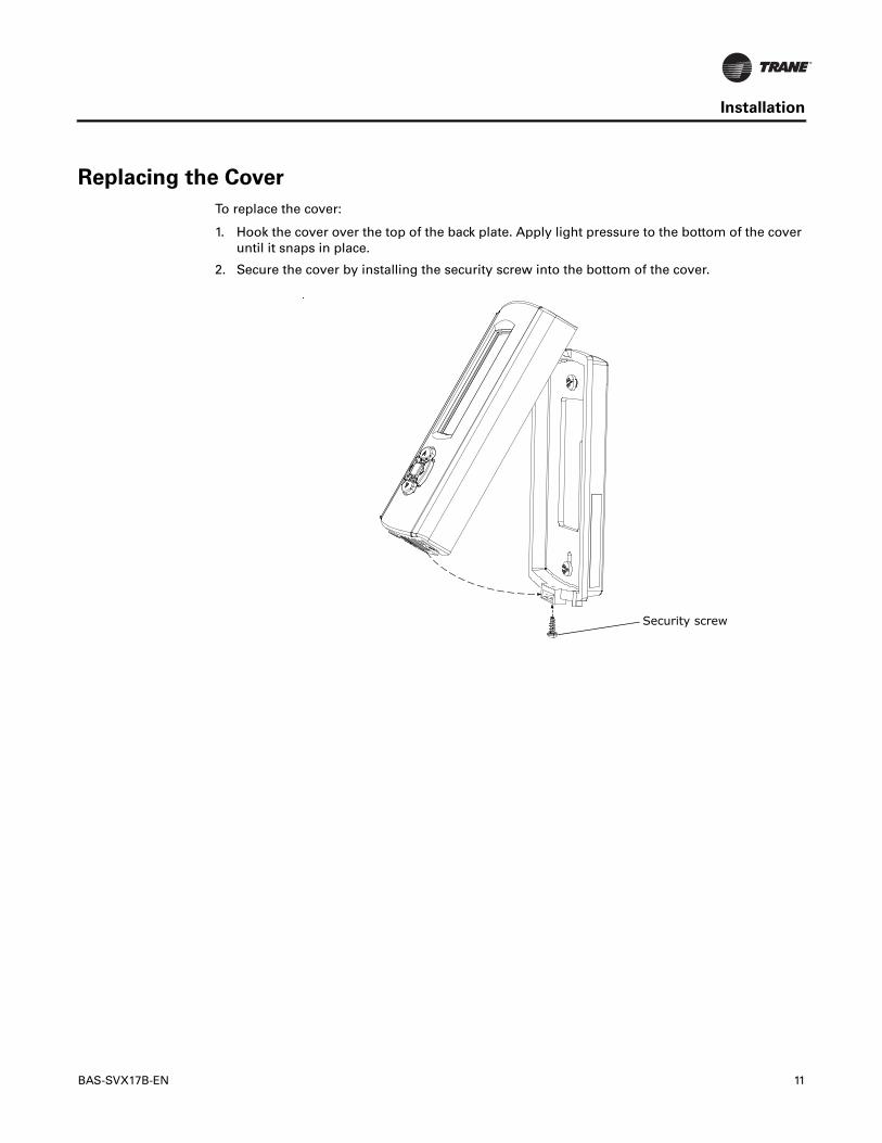
To replace the cover:
1. Hook the cover over the top of the back plate. Apply light pressure to the bottom of the cover until it snaps in place.
2. Secure the cover by installing the security screw into the bottom of the cover.
Security screw
12 BAS-SVX17B-EN
Installation
Applying Power to the Sensor
Restore power to the unit controller. The following sequence appears on the display:
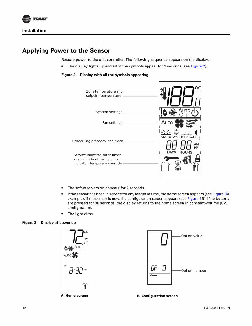
• The display lights up and all of the symbols appear for 2 seconds (see Figure 2).
• The software version appears for 2 seconds.
• If the sensor has been in service for any length of time, the home screen appears (see Figure 3A example). If the sensor is new, the configuration screen appears (see Figure 3B). If no buttons are pressed for 90 seconds, the display returns to the home screen in constant-volume (CV) configuration.
• The light dims.
Figure 2. Display with all the symbols appearing
AM
PM
DAYS HOURS
Mo Tu We Th Fr Sat Su
.
Service indicator, filter timer, keypad lockout, occupancy indicator, temporary override
Zone temperature and setpoint temperature
System settings
Fan settings
Scheduling area/day and clock
Figure 3. Display at power-up
..Mo
AM
A. Home screen B. Configuration screen
Option value
Option number
BAS-SVX17B-EN 13
Configuration
The programmable zone sensor is configured by selecting options to determine system and functional operations.
The sensor can be configured to operate with one of the following units:
• A constant-volume (CV) unit
• A heat pump (HP) unit
• A variable-air-volume (VAV) unit
The functional options that are available depend on whether the sensor is configured for a CV, an HP, or a VAV unit.
To configure the sensor:
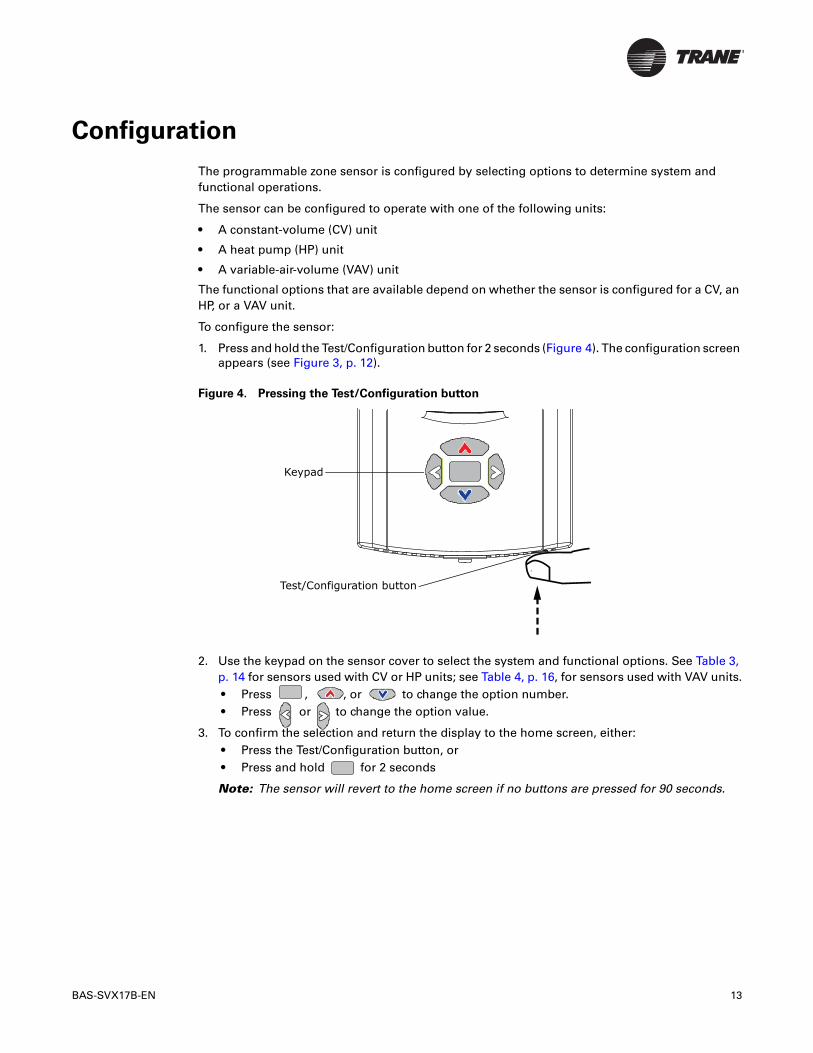
1. Press and hold the Test/Configuration button for 2 seconds (Figure 4). The configuration screen appears (see Figure 3, p. 12).
2. Use the keypad on the sensor cover to select the system and functional options. See Table 3, p. 14 for sensors used with CV or HP units; see Table 4, p. 16, for sensors used with VAV units.• Press , , or to change the option number.• Press or to change the option value.
3. To confirm the selection and return the display to the home screen, either:• Press the Test/Configuration button, or• Press and hold for 2 seconds
Note: The sensor will revert to the home screen if no buttons are pressed for 90 seconds.
Figure 4. Pressing the Test/Configuration button
Test/Configuration button
Keypad
14 BAS-SVX17B-EN
Configuration
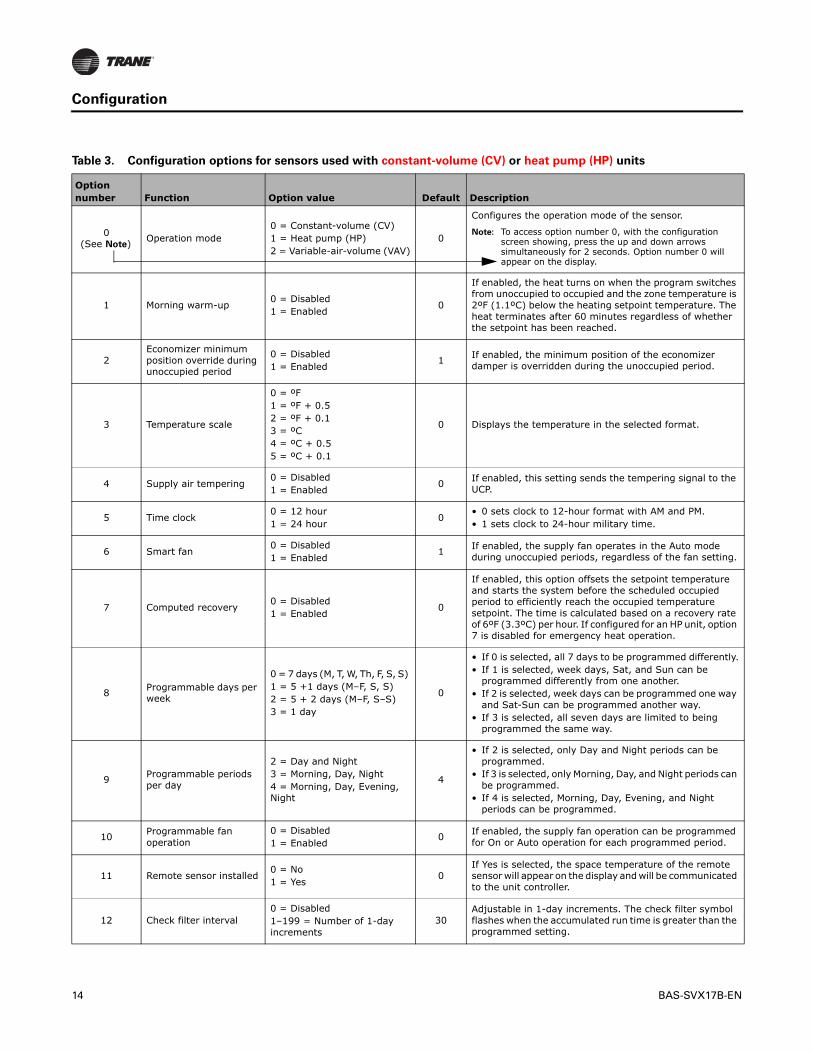
Table 3. Configuration options for sensors used with constant-volume (CV) or heat pump (HP) units
Option number Function Option value Default Description
0(See Note)
Operation mode0 = Constant-volume (CV)1 = Heat pump (HP)2 = Variable-air-volume (VAV)
0
Configures the operation mode of the sensor.
Note: To access option number 0, with the configuration screen showing, press the up and down arrows simultaneously for 2 seconds. Option number 0 will appear on the display.
1 Morning warm-up0 = Disabled 1 = Enabled
0
If enabled, the heat turns on when the program switches from unoccupied to occupied and the zone temperature is 2ºF (1.1ºC) below the heating setpoint temperature. The heat terminates after 60 minutes regardless of whether the setpoint has been reached.
2Economizer minimum position override during unoccupied period
0 = Disabled 1 = Enabled
1If enabled, the minimum position of the economizer damper is overridden during the unoccupied period.
3 Temperature scale
0 = ºF1 = ºF + 0.52 = ºF + 0.13 = ºC4 = ºC + 0.55 = ºC + 0.1
0 Displays the temperature in the selected format.
4 Supply air tempering0 = Disabled 1 = Enabled
0If enabled, this setting sends the tempering signal to the UCP.
5 Time clock0 = 12 hour1 = 24 hour
0• 0 sets clock to 12-hour format with AM and PM.• 1 sets clock to 24-hour military time.
6 Smart fan0 = Disabled 1 = Enabled
1If enabled, the supply fan operates in the Auto mode during unoccupied periods, regardless of the fan setting.
7 Computed recovery0 = Disabled 1 = Enabled
0
If enabled, this option offsets the setpoint temperature and starts the system before the scheduled occupied period to efficiently reach the occupied temperature setpoint. The time is calculated based on a recovery rate of 6ºF (3.3ºC) per hour. If configured for an HP unit, option 7 is disabled for emergency heat operation.
8Programmable days per week
0 = 7 days (M, T, W, Th, F, S, S) 1 = 5 +1 days (M–F, S, S) 2 = 5 + 2 days (M–F, S–S) 3 = 1 day
0
• If 0 is selected, all 7 days to be programmed differently.• If 1 is selected, week days, Sat, and Sun can be
programmed differently from one another. • If 2 is selected, week days can be programmed one way
and Sat-Sun can be programmed another way. • If 3 is selected, all seven days are limited to being
programmed the same way.
9Programmable periods per day
2 = Day and Night3 = Morning, Day, Night4 = Morning, Day, Evening, Night
4
• If 2 is selected, only Day and Night periods can be programmed.
• If 3 is selected, only Morning, Day, and Night periods can be programmed.
• If 4 is selected, Morning, Day, Evening, and Night periods can be programmed.
10Programmable fan operation
0 = Disabled1 = Enabled
0If enabled, the supply fan operation can be programmed for On or Auto operation for each programmed period.
11 Remote sensor installed0 = No1 = Yes
0If Yes is selected, the space temperature of the remote sensor will appear on the display and will be communicated to the unit controller.
12 Check filter interval0 = Disabled1–199 = Number of 1-day increments
30Adjustable in 1-day increments. The check filter symbol flashes when the accumulated run time is greater than the programmed setting.
BAS-SVX17B-EN 15
Configuration
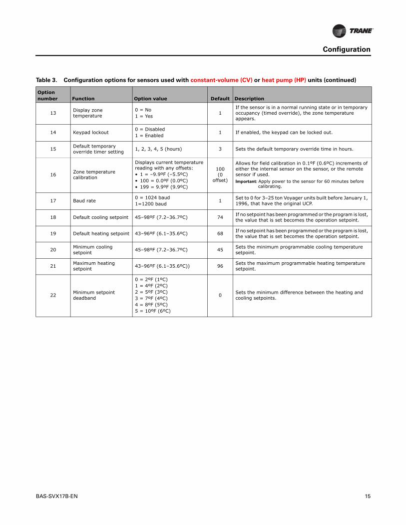
13Display zone temperature
0 = No 1 = Yes
1If the sensor is in a normal running state or in temporary occupancy (timed override), the zone temperature appears.
14 Keypad lockout0 = Disabled 1 = Enabled
1 If enabled, the keypad can be locked out.
15Default temporary override timer setting
1, 2, 3, 4, 5 (hours) 3 Sets the default temporary override time in hours.
16Zone temperature calibration
Displays current temperature reading with any offsets:• 1 = –9.9ºF (–5.5ºC)• 100 = 0.0ºF (0.0ºC)• 199 = 9.9ºF (9.9ºC)
100 (0
offset)
Allows for field calibration in 0.1ºF (0.6ºC) increments of either the internal sensor on the sensor, or the remote sensor if used.Important: Apply power to the sensor for 60 minutes before
calibrating.
17 Baud rate0 = 1024 baud1=1200 baud
1Set to 0 for 3–25 ton Voyager units built before January 1, 1996, that have the original UCP.
18 Default cooling setpoint 45–98ºF (7.2–36.7ºC) 74If no setpoint has been programmed or the program is lost, the value that is set becomes the operation setpoint.
19 Default heating setpoint 43–96ºF (6.1–35.6ºC) 68If no setpoint has been programmed or the program is lost, the value that is set becomes the operation setpoint.
20Minimum cooling setpoint
45–98ºF (7.2–36.7ºC) 45Sets the minimum programmable cooling temperature setpoint.
21Maximum heating setpoint 43–96ºF (6.1–35.6ºC)) 96
Sets the maximum programmable heating temperature setpoint.
22Minimum setpoint deadband
0 = 2ºF (1ºC)1 = 4ºF (2ºC)2 = 5ºF (3ºC)3 = 7ºF (4ºC)4 = 8ºF (5ºC)5 = 10ºF (6ºC)
0Sets the minimum difference between the heating and cooling setpoints.
Table 3. Configuration options for sensors used with constant-volume (CV) or heat pump (HP) units (continued)
Option number Function Option value Default Description
16 BAS-SVX17B-EN
Configuration
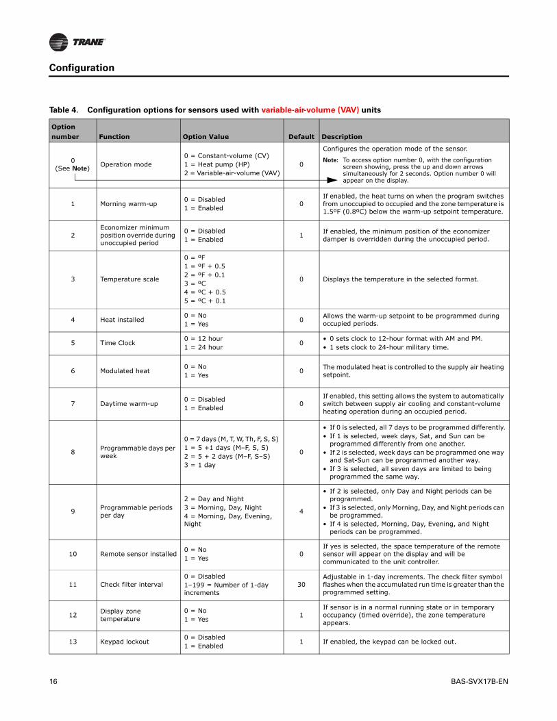
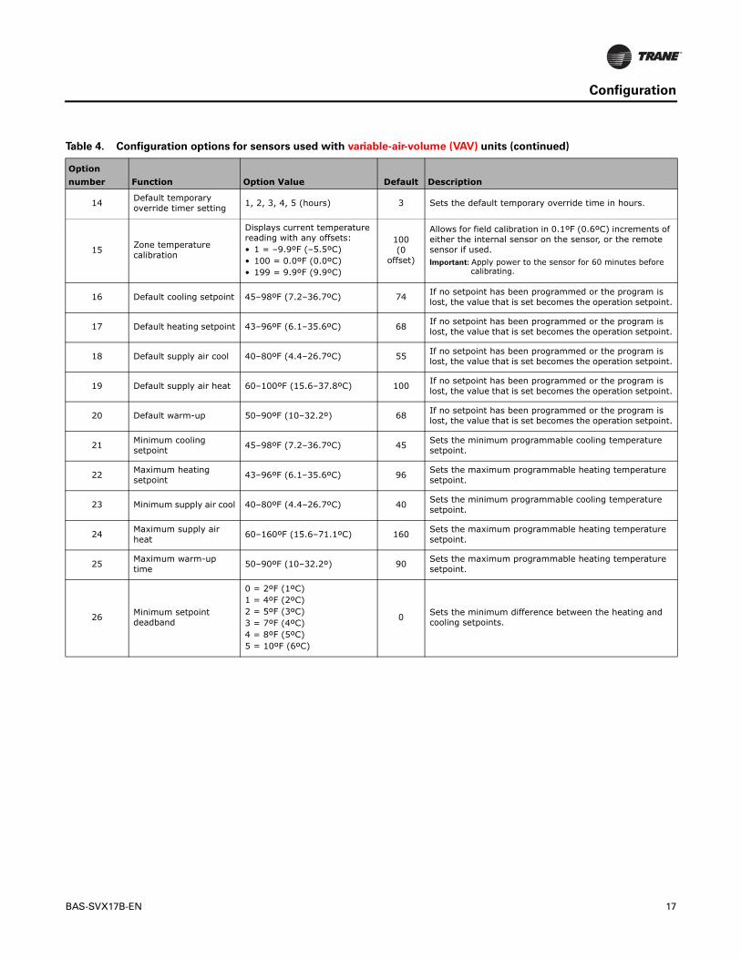
Table 4. Configuration options for sensors used with variable-air-volume (VAV) units
Option
number Function Option Value Default Description
0(See Note)
Operation mode0 = Constant-volume (CV)1 = Heat pump (HP)2 = Variable-air-volume (VAV)
0
Configures the operation mode of the sensor.
Note: To access option number 0, with the configuration screen showing, press the up and down arrows simultaneously for 2 seconds. Option number 0 will appear on the display.
1 Morning warm-up0 = Disabled 1 = Enabled
0If enabled, the heat turns on when the program switches from unoccupied to occupied and the zone temperature is 1.5ºF (0.8ºC) below the warm-up setpoint temperature.
2Economizer minimum position override during unoccupied period
0 = Disabled 1 = Enabled
1If enabled, the minimum position of the economizer damper is overridden during the unoccupied period.
3 Temperature scale
0 = ºF1 = ºF + 0.52 = ºF + 0.13 = ºC4 = ºC + 0.55 = ºC + 0.1
0 Displays the temperature in the selected format.
4 Heat installed0 = No1 = Yes
0Allows the warm-up setpoint to be programmed during occupied periods.
5 Time Clock0 = 12 hour 1 = 24 hour
0• 0 sets clock to 12-hour format with AM and PM.• 1 sets clock to 24-hour military time.
6 Modulated heat0 = No1 = Yes
0The modulated heat is controlled to the supply air heating setpoint.
7 Daytime warm-up0 = Disabled1 = Enabled
0If enabled, this setting allows the system to automatically switch between supply air cooling and constant-volume heating operation during an occupied period.
8Programmable days per week
0 = 7 days (M, T, W, Th, F, S, S) 1 = 5 +1 days (M–F, S, S) 2 = 5 + 2 days (M–F, S–S) 3 = 1 day
0
• If 0 is selected, all 7 days to be programmed differently.• If 1 is selected, week days, Sat, and Sun can be
programmed differently from one another. • If 2 is selected, week days can be programmed one way
and Sat-Sun can be programmed another way. • If 3 is selected, all seven days are limited to being
programmed the same way.
9Programmable periods per day
2 = Day and Night3 = Morning, Day, Night4 = Morning, Day, Evening, Night
4
• If 2 is selected, only Day and Night periods can be programmed.
• If 3 is selected, only Morning, Day, and Night periods can be programmed.
• If 4 is selected, Morning, Day, Evening, and Night periods can be programmed.
10 Remote sensor installed0 = No1 = Yes
0If yes is selected, the space temperature of the remote sensor will appear on the display and will be communicated to the unit controller.
11 Check filter interval0 = Disabled1–199 = Number of 1-day increments
30Adjustable in 1-day increments. The check filter symbol flashes when the accumulated run time is greater than the programmed setting.
12Display zone temperature
0 = No 1 = Yes
1If sensor is in a normal running state or in temporary occupancy (timed override), the zone temperature appears.
13 Keypad lockout0 = Disabled 1 = Enabled
1 If enabled, the keypad can be locked out.
BAS-SVX17B-EN 17
Configuration
14Default temporary override timer setting
1, 2, 3, 4, 5 (hours) 3 Sets the default temporary override time in hours.
15Zone temperature calibration
Displays current temperature reading with any offsets:• 1 = –9.9ºF (–5.5ºC)• 100 = 0.0ºF (0.0ºC)• 199 = 9.9ºF (9.9ºC)
100 (0
offset)
Allows for field calibration in 0.1ºF (0.6ºC) increments of either the internal sensor on the sensor, or the remote sensor if used.Important: Apply power to the sensor for 60 minutes before
calibrating.
16 Default cooling setpoint 45–98ºF (7.2–36.7ºC) 74If no setpoint has been programmed or the program is lost, the value that is set becomes the operation setpoint.
17 Default heating setpoint 43–96ºF (6.1–35.6ºC) 68If no setpoint has been programmed or the program is lost, the value that is set becomes the operation setpoint.
18 Default supply air cool 40–80ºF (4.4–26.7ºC) 55If no setpoint has been programmed or the program is lost, the value that is set becomes the operation setpoint.
19 Default supply air heat 60–100ºF (15.6–37.8ºC) 100If no setpoint has been programmed or the program is lost, the value that is set becomes the operation setpoint.
20 Default warm-up 50–90ºF (10–32.2º) 68If no setpoint has been programmed or the program is lost, the value that is set becomes the operation setpoint.
21Minimum cooling setpoint 45–98ºF (7.2–36.7ºC) 45
Sets the minimum programmable cooling temperature setpoint.
22Maximum heating setpoint
43–96ºF (6.1–35.6ºC) 96Sets the maximum programmable heating temperature setpoint.
23 Minimum supply air cool 40–80ºF (4.4–26.7ºC) 40Sets the minimum programmable cooling temperature setpoint.
24Maximum supply air heat
60–160ºF (15.6–71.1ºC) 160Sets the maximum programmable heating temperature setpoint.
25Maximum warm-up time
50–90ºF (10–32.2º) 90Sets the maximum programmable heating temperature setpoint.
26 Minimum setpoint deadband
0 = 2ºF (1ºC)1 = 4ºF (2ºC)2 = 5ºF (3ºC)3 = 7ºF (4ºC)4 = 8ºF (5ºC)5 = 10ºF (6ºC)
0 Sets the minimum difference between the heating and cooling setpoints.
Table 4. Configuration options for sensors used with variable-air-volume (VAV) units (continued)
Option
number Function Option Value Default Description
18 BAS-SVX17B-EN
Operation
This section describes sensor operations, explains sensor symbols, and provides the default settings.
Set-up Procedures
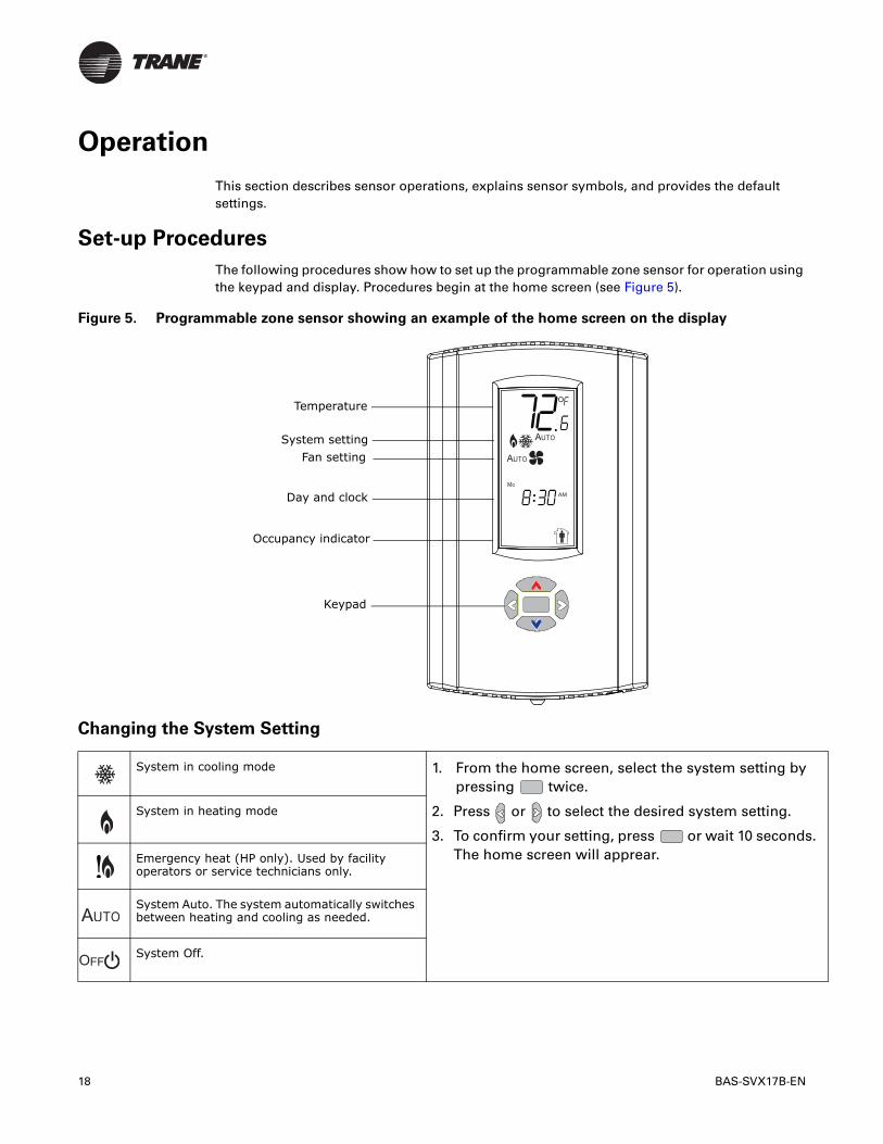
The following procedures show how to set up the programmable zone sensor for operation using the keypad and display. Procedures begin at the home screen (see Figure 5).
Changing the System Setting
Figure 5. Programmable zone sensor showing an example of the home screen on the display
System in cooling mode 1. From the home screen, select the system setting by pressing twice.
2. Press or to select the desired system setting.
3. To confirm your setting, press or wait 10 seconds. The home screen will apprear.
System in heating mode
Emergency heat (HP only). Used by facility operators or service technicians only.
System Auto. The system automatically switches between heating and cooling as needed.
System Off.
..Mo
AM
Keypad
Occupancy indicator
Temperature
System setting
Fan setting
Day and clock
BAS-SVX17B-EN 19
Operation
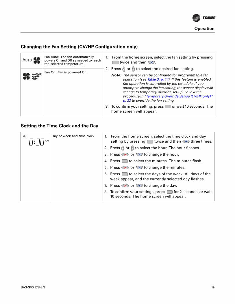
Changing the Fan Setting (CV/HP Configuration only)
Setting the Time Clock and the Day
Fan Auto: The fan automatically powers On and Off as needed to reach the selected temperature.
1. From the home screen, select the fan setting by pressing twice and then .
2. Press or to select the desired fan setting.
Note: The sensor can be configured for programmable fan operation (see Table 3, p. 14). If this feature is enabled, fan operation is controlled by the schedule. If you attempt to change the fan setting, the sensor display will change to temporary override set-up. Follow the procedure in “Temporary Override Set-up (CV/HP only),” p. 22 to override the fan setting.
3. To confirm your setting, press or wait 10 seconds. The home screen will appear.
Fan On: Fan is powered On.
Day of week and time clock 1. From the home screen, select the time clock and day setting by pressing twice and then three times.
2. Press or to select the hour. The hour flashes.
3. Press or to change the hour.
4. Press to select the minutes. The minutes flash.
5. Press or to change the minutes.
6. Press to select the days of the week. All days of the week appear, and the currently selected day flashes.
7. Press or to change the day.
8. To confirm your settings, press for 2 seconds, or wait 10 seconds. The home screen will appear.
..Mo
AM
20 BAS-SVX17B-EN
Operation
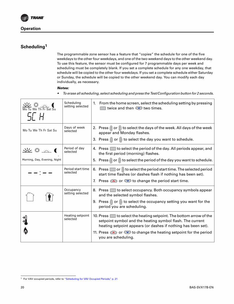
Scheduling1
The programmable zone sensor has a feature that “copies” the schedule for one of the five weekdays to the other four weekdays, and one of the two weekend days to the other weekend day. To use this feature, the sensor must be configured for 7 programmable days per week and scheduling must be completely blank. If you set a complete schedule for any one weekday, that schedule will be copied to the other four weekdays. If you set a complete schedule either Saturday or Sunday, the schedule will be copied to the other weekend day. You can modify each day individually, as necessary.
Notes:
• To erase all scheduling, select scheduling and press the Test/Configuration button for 2 seconds.
1 For VAV occupied periods, refer to “Scheduling for VAV Occupied Periods,” p. 21
Scheduling setting selected
1. From the home screen, select the scheduling setting by pressing twice and then two times.
Days of week selected
2. Press or to select the days of the week. All days of the week appear and Monday flashes.
3. Press or to select the day you want to schedule.
Morning, Day, Evening, Night
Period of day selected
4. Press to select the period of the day. All periods appear, and the first period (morning) flashes.
5. Press or to select the period of the day you want to schedule.
Period start time selected
6. Press or to select the period start time. The selected period start time flashes (or dashes flash if nothing has been set).
7. Press or to change the period start time.
Occupancy setting selected
8. Press to select occupancy. Both occupancy symbols appear and the selected symbol flashes.
9. Press or to select the occupancy setting you want for the period you are scheduling.
Heating setpoint selected
10. Press to select the heating setpoint. The bottom arrow of the setpoint symbol and the heating symbol flash. The current heating setpoint appears (or dashes if nothing has been set).
11. Press or to change the heating setpoint for the period you are scheduling.
Mo Tu We Th Fr Sat Su
Mo Tu We Th Fr Sat Su
BAS-SVX17B-EN 21
Operation
Scheduling for VAV Occupied Periods
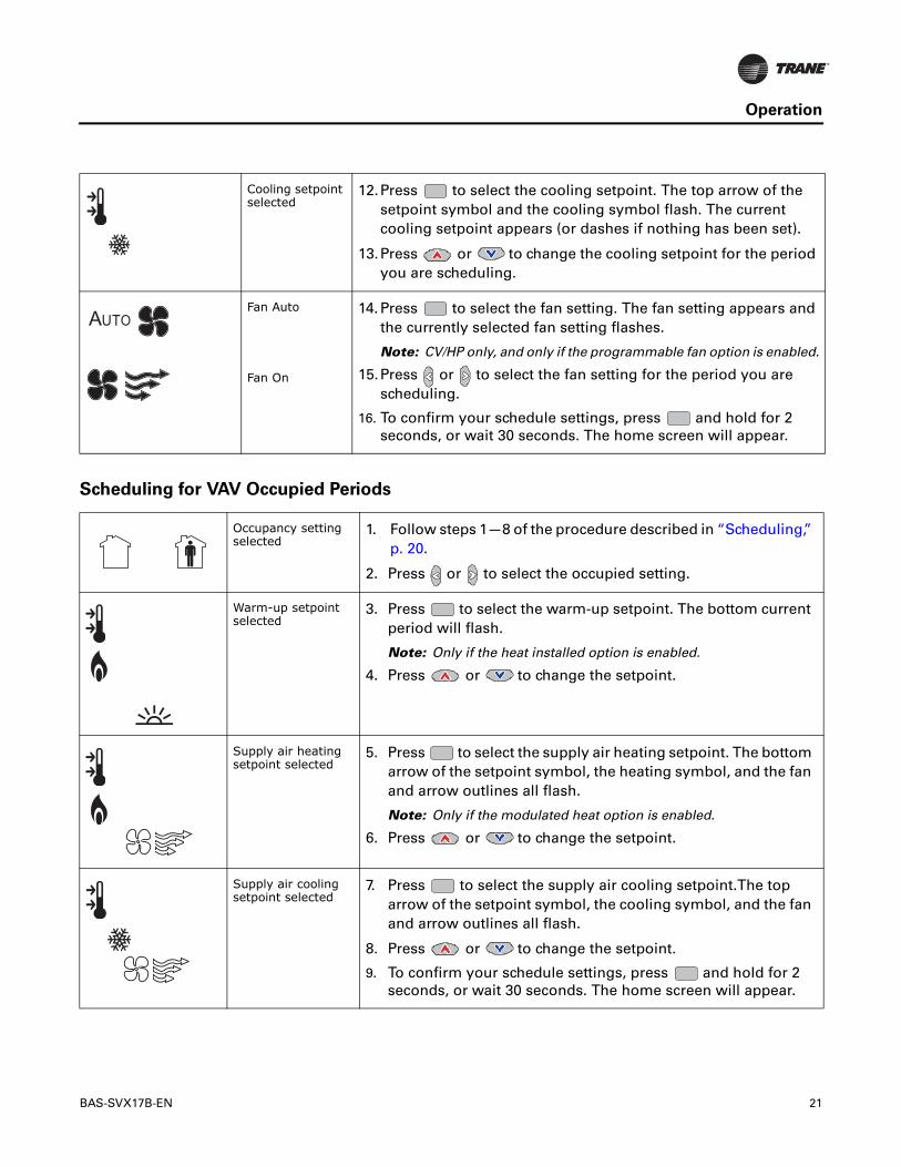
Cooling setpoint selected
12.Press to select the cooling setpoint. The top arrow of the setpoint symbol and the cooling symbol flash. The current cooling setpoint appears (or dashes if nothing has been set).
13.Press or to change the cooling setpoint for the period you are scheduling.
Fan Auto
Fan On
14. Press to select the fan setting. The fan setting appears and the currently selected fan setting flashes.
Note: CV/HP only, and only if the programmable fan option is enabled.
15.Press or to select the fan setting for the period you are scheduling.
16. To confirm your schedule settings, press and hold for 2 seconds, or wait 30 seconds. The home screen will appear.
Occupancy setting selected
1. Follow steps 1—8 of the procedure described in “Scheduling,” p. 20.
2. Press or to select the occupied setting.
Warm-up setpoint selected
3. Press to select the warm-up setpoint. The bottom current period will flash.
Note: Only if the heat installed option is enabled.
4. Press or to change the setpoint.
Supply air heating setpoint selected
5. Press to select the supply air heating setpoint. The bottom arrow of the setpoint symbol, the heating symbol, and the fan and arrow outlines all flash.
Note: Only if the modulated heat option is enabled.
6. Press or to change the setpoint.
Supply air cooling setpoint selected
7. Press to select the supply air cooling setpoint.The top arrow of the setpoint symbol, the cooling symbol, and the fan and arrow outlines all flash.
8. Press or to change the setpoint.
9. To confirm your schedule settings, press and hold for 2 seconds, or wait 30 seconds. The home screen will appear.
22 BAS-SVX17B-EN
Operation
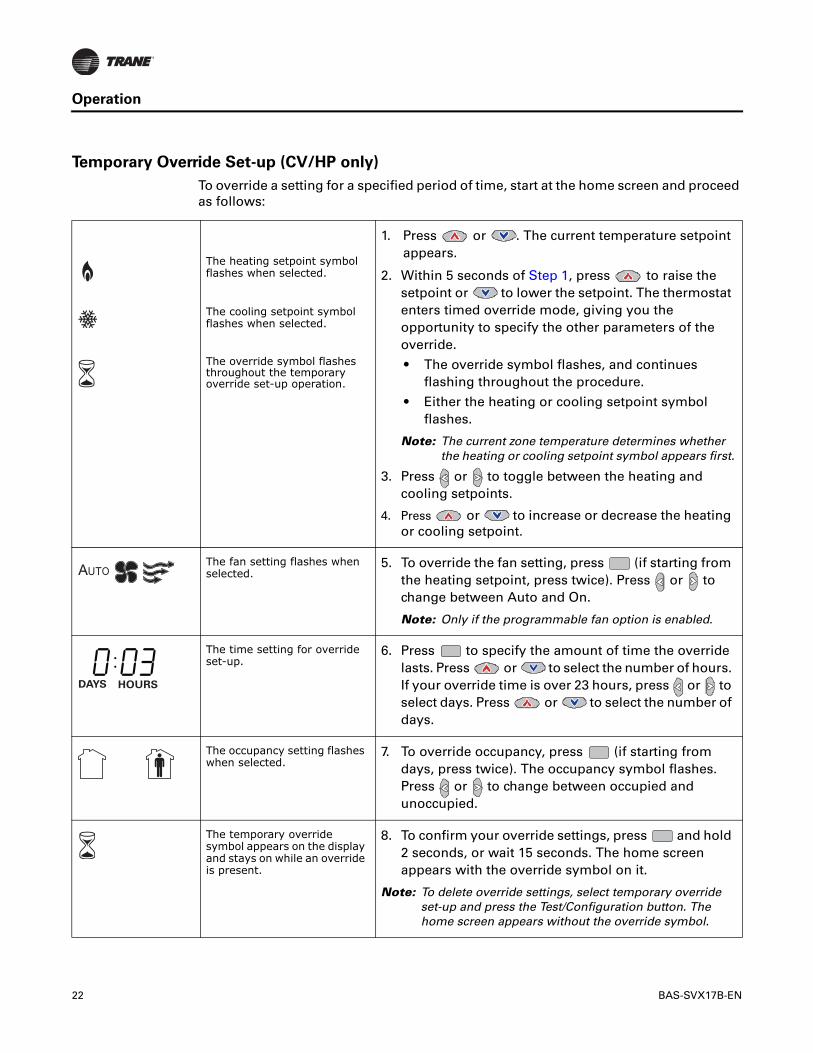
Temporary Override Set-up (CV/HP only)
To override a setting for a specified period of time, start at the home screen and proceed as follows:
The heating setpoint symbol flashes when selected.
The cooling setpoint symbol flashes when selected.
The override symbol flashes throughout the temporary override set-up operation.
1. Press or . The current temperature setpoint appears.
2. Within 5 seconds of Step 1, press to raise the setpoint or to lower the setpoint. The thermostat enters timed override mode, giving you the opportunity to specify the other parameters of the override.
• The override symbol flashes, and continues flashing throughout the procedure.
• Either the heating or cooling setpoint symbol flashes.
Note: The current zone temperature determines whether the heating or cooling setpoint symbol appears first.
3. Press or to toggle between the heating and cooling setpoints.
4. Press or to increase or decrease the heating or cooling setpoint.
The fan setting flashes when selected.
5. To override the fan setting, press (if starting from the heating setpoint, press twice). Press or to change between Auto and On.
Note: Only if the programmable fan option is enabled.
The time setting for override set-up.
6. Press to specify the amount of time the override lasts. Press or to select the number of hours. If your override time is over 23 hours, press or to select days. Press or to select the number of days.
The occupancy setting flashes when selected.
7. To override occupancy, press (if starting from days, press twice). The occupancy symbol flashes. Press or to change between occupied and unoccupied.
The temporary override symbol appears on the display and stays on while an override is present.
8. To confirm your override settings, press and hold 2 seconds, or wait 15 seconds. The home screen appears with the override symbol on it.
Note: To delete override settings, select temporary override set-up and press the Test/Configuration button. The home screen appears without the override symbol.
DAYS HOURS
BAS-SVX17B-EN 23
Operation
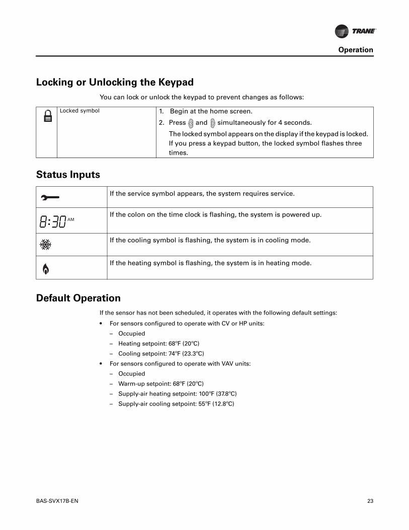
Locking or Unlocking the Keypad
You can lock or unlock the keypad to prevent changes as follows:
Status Inputs
Default Operation
If the sensor has not been scheduled, it operates with the following default settings:
• For sensors configured to operate with CV or HP units:
– Occupied
– Heating setpoint: 68ºF (20ºC)
– Cooling setpoint: 74ºF (23.3ºC)
• For sensors configured to operate with VAV units:
– Occupied
– Warm-up setpoint: 68ºF (20ºC)
– Supply-air heating setpoint: 100ºF (37.8ºC)
– Supply-air cooling setpoint: 55ºF (12.8ºC)
Locked symbol 1. Begin at the home screen.
2. Press and simultaneously for 4 seconds.
The locked symbol appears on the display if the keypad is locked. If you press a keypad button, the locked symbol flashes three times.
If the service symbol appears, the system requires service.
If the colon on the time clock is flashing, the system is powered up.
If the cooling symbol is flashing, the system is in cooling mode.
If the heating symbol is flashing, the system is in heating mode.
.. AM
24 BAS-SVX17B-EN
Operation
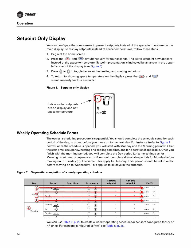
Setpoint Only Display
You can configure the zone sensor to present setpoints instead of the space temperature on the main display. To display setpoints instead of space temperatures, follow these steps:
1. Begin at the home screen
2. Press the and simultaneously for four seconds. The active setpoint now appears instead of the space temperature. Setpoint presentation is indicated by an arrow in the upper left corner of the display (see Figure 6).
3. Press or to toggle between the heating and cooling setpoints.
4. To return to showing space temperature on the display, press the and simultaneously for four seconds.
Weekly Operating Schedule Forms
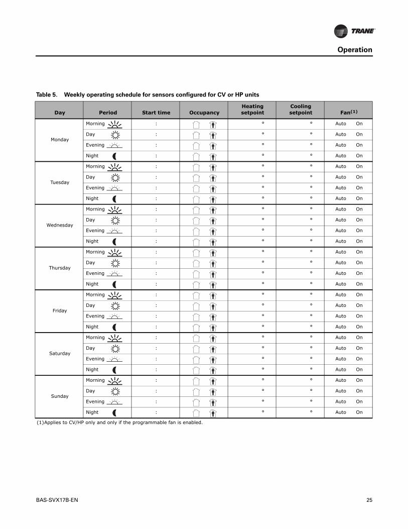
The easiest scheduling procedure is sequential. You should complete the schedule setup for each period of the day, in order, before you move on to the next day. For instance (refer to Figure 7 below), once the schedule is opened, you will start with Monday and the Morning period (1). Set the start time, occupancy, heating and cooling setpoints, and fan operation if applicable. Once you finish with the morning period, you will complete the Day period (2)(same settings as for Morning...start time, occupancy, etc.). You should complete all available periods for Monday before moving on to Tuesday (5). The same rules apply for Tuesday. Each period should be set in order before moving on to Wednesday. This applies to all days in the schedule.
You can use Table 5, p. 25 to create a weekly operating schedule for sensors configured for CV or HP units. For sensors configured as VAV, see Table 6, p. 26.
Figure 6. Setpoint only display
Indicates that setpoints are on display and not space temperature
Figure 7. Sequential completion of a weely operating schedule.
BAS-SVX17B-EN 25
Operation
Table 5. Weekly operating schedule for sensors configured for CV or HP units
Day Period Start time OccupancyHeating setpoint
Cooling setpoint Fan(1)
Monday
Morning : ° ° Auto On
Day : ° ° Auto On
Evening : ° ° Auto On
Night : ° ° Auto On
Tuesday
Morning : ° ° Auto On
Day : ° ° Auto On
Evening : ° ° Auto On
Night : ° ° Auto On
Wednesday
Morning : ° ° Auto On
Day : ° ° Auto On
Evening : ° ° Auto On
Night : ° ° Auto On
Thursday
Morning : ° ° Auto On
Day : ° ° Auto On
Evening : ° ° Auto On
Night : ° ° Auto On
Friday
Morning : ° ° Auto On
Day : ° ° Auto On
Evening : ° ° Auto On
Night : ° ° Auto On
Saturday
Morning : ° ° Auto On
Day : ° ° Auto On
Evening : ° ° Auto On
Night : ° ° Auto On
Sunday
Morning : ° ° Auto On
Day : ° ° Auto On
Evening : ° ° Auto On
Night : ° ° Auto On
(1)Applies to CV/HP only and only if the programmable fan is enabled.
26 BAS-SVX17B-EN
Operation
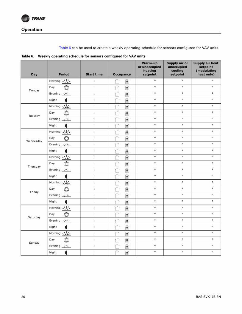
Table 6 can be used to create a weekly operating schedule for sensors configured for VAV units.
Table 6. Weekly operating schedule for sensors configured for VAV units
Day Period Start time Occupancy
Warm-upor unoccupied
heating setpoint
Supply air or unoccupied
cooling setpoint
Supply air heat setpoint
(modulating heat only)
Monday
Morning : ° ° °
Day : ° ° °
Evening : ° ° °
Night : ° ° °
Tuesday
Morning : ° ° °
Day : ° ° °
Evening : ° ° °
Night : ° ° °
Wednesday
Morning : ° ° °
Day : ° ° °
Evening : ° ° °
Night : ° ° °
Thursday
Morning : ° ° °
Day : ° ° °
Evening : ° ° °
Night : ° ° °
Friday
Morning : ° ° °
Day : ° ° °
Evening : ° ° °
Night : ° ° °
Saturday
Morning : ° ° °
Day : ° ° °
Evening : ° ° °
Night : ° ° °
Sunday
Morning : ° ° °
Day : ° ° °
Evening : ° ° °
Night : ° ° °
BAS-SVX17B-EN 27
Maintenance and Troubleshooting
This section describes maintenance and troubleshooting for the programmable zone sensor.
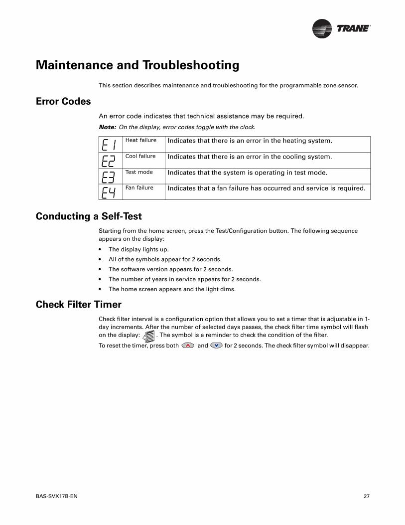
Error Codes
An error code indicates that technical assistance may be required.
Note: On the display, error codes toggle with the clock.
Conducting a Self-Test
Starting from the home screen, press the Test/Configuration button. The following sequence appears on the display:
• The display lights up.
• All of the symbols appear for 2 seconds.
• The software version appears for 2 seconds.
• The number of years in service appears for 2 seconds.
• The home screen appears and the light dims.
Check Filter Timer
Check filter interval is a configuration option that allows you to set a timer that is adjustable in 1-day increments. After the number of selected days passes, the check filter time symbol will flash on the display: . The symbol is a reminder to check the condition of the filter.
To reset the timer, press both and for 2 seconds. The check filter symbol will disappear.
Heat failure Indicates that there is an error in the heating system.
Cool failure Indicates that there is an error in the cooling system.
Test mode Indicates that the system is operating in test mode.
Fan failure Indicates that a fan failure has occurred and service is required.
28 BAS-SVX17B-EN
Maintenance and Troubleshooting
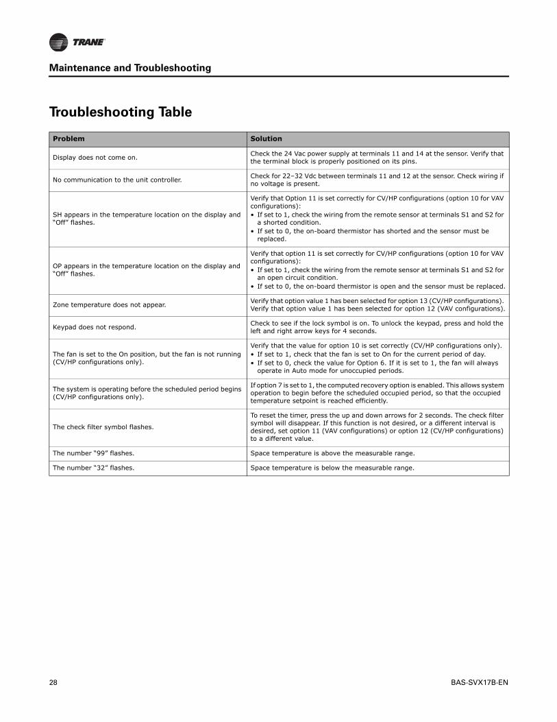
Troubleshooting Table
Problem Solution
Display does not come on. Check the 24 Vac power supply at terminals 11 and 14 at the sensor. Verify that the terminal block is properly positioned on its pins.
No communication to the unit controller.Check for 22–32 Vdc between terminals 11 and 12 at the sensor. Check wiring if no voltage is present.
SH appears in the temperature location on the display and “Off” flashes.
Verify that Option 11 is set correctly for CV/HP configurations (option 10 for VAV configurations):• If set to 1, check the wiring from the remote sensor at terminals S1 and S2 for
a shorted condition. • If set to 0, the on-board thermistor has shorted and the sensor must be
replaced.
OP appears in the temperature location on the display and “Off” flashes.
Verify that option 11 is set correctly for CV/HP configurations (option 10 for VAV configurations):• If set to 1, check the wiring from the remote sensor at terminals S1 and S2 for
an open circuit condition.• If set to 0, the on-board thermistor is open and the sensor must be replaced.
Zone temperature does not appear.Verify that option value 1 has been selected for option 13 (CV/HP configurations). Verify that option value 1 has been selected for option 12 (VAV configurations).
Keypad does not respond.Check to see if the lock symbol is on. To unlock the keypad, press and hold the left and right arrow keys for 4 seconds.
The fan is set to the On position, but the fan is not running (CV/HP configurations only).
Verify that the value for option 10 is set correctly (CV/HP configurations only).• If set to 1, check that the fan is set to On for the current period of day.• If set to 0, check the value for Option 6. If it is set to 1, the fan will always
operate in Auto mode for unoccupied periods.
The system is operating before the scheduled period begins (CV/HP configurations only).
If option 7 is set to 1, the computed recovery option is enabled. This allows system operation to begin before the scheduled occupied period, so that the occupied temperature setpoint is reached efficiently.
The check filter symbol flashes.
To reset the timer, press the up and down arrows for 2 seconds. The check filter symbol will disappear. If this function is not desired, or a different interval is desired, set option 11 (VAV configurations) or option 12 (CV/HP configurations) to a different value.
The number “99” flashes. Space temperature is above the measurable range.
The number “32” flashes. Space temperature is below the measurable range.
BAS-SVX17B-EN 29
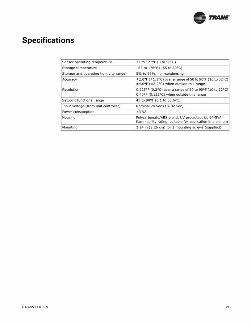
Specifications
Sensor operating temperature 32 to 122ºF (0 to 50ºC)
Storage temperature –67 to 176ºF (–55 to 80°C)
Storage and operating humidity range 5% to 95%, non-condensing
Accuracy ±2.0°F (±1.1°C) over a range of 50 to 90°F (10 to 32°C)±4.0°F (±2.2°C) when outside this range
Resolution 0.225ºF (0.2°C) over a range of 50 to 90ºF (10 to 32°C)0.40ºF (0.125°C) when outside this range
Setpoint functional range 43 to 98ºF (6.1 to 36.6ºC)
Input voltage (from unit controller) Nominal 24 Vac (18–32 Vac)
Power consumption <3 VA
Housing Polycarbonate/ABS blend, UV protected, UL 94-5VA flammability rating, suitable for application in a plenum
Mounting 3.24 in (8.26 cm) for 2 mounting screws (supplied)
30 BAS-SVX17B-EN
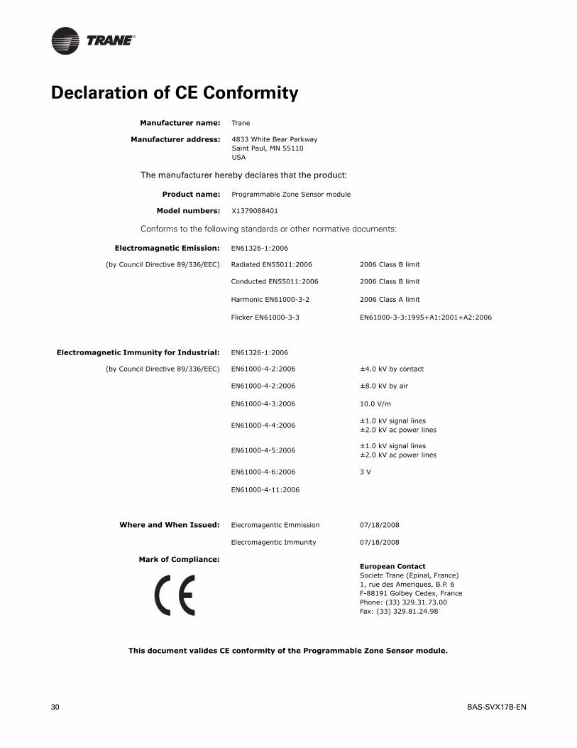
Declaration of CE Conformity
The manufacturer hereby declares that the product:
Conforms to the following standards or other normative documents:
Manufacturer name: Trane
Manufacturer address: 4833 White Bear ParkwaySaint Paul, MN 55110 USA
Product name: Programmable Zone Sensor module
Model numbers: X1379088401
Electromagnetic Emission: EN61326-1:2006
(by Council Directive 89/336/EEC) Radiated EN55011:2006 2006 Class B limit
Conducted EN55011:2006 2006 Class B limit
Harmonic EN61000-3-2 2006 Class A limit
Flicker EN61000-3-3 EN61000-3-3:1995+A1:2001+A2:2006
Electromagnetic Immunity for Industrial: EN61326-1:2006
(by Council Directive 89/336/EEC) EN61000-4-2:2006 ±4.0 kV by contact
EN61000-4-2:2006 ±8.0 kV by air
EN61000-4-3:2006 10.0 V/m
EN61000-4-4:2006±1.0 kV signal lines±2.0 kV ac power lines
EN61000-4-5:2006±1.0 kV signal lines±2.0 kV ac power lines
EN61000-4-6:2006 3 V
EN61000-4-11:2006
Where and When Issued: Elecromagentic Emmission 07/18/2008
Elecromagentic Immunity 07/18/2008
Mark of Compliance:European ContactSocietE Trane (Epinal, France)1, rue des Ameriques, B.P. 6F-88191 Golbey Cedex, FrancePhone: (33) 329.31.73.00Fax: (33) 329.81.24.98
This document valides CE conformity of the Programmable Zone Sensor module.
BAS-SVX17B-EN 31
Declaration of CE Conformity
Notes:

Trane optimizes the performance of homes and buildings around the world. A business of Ingersoll Rand, the leader in creating and sustaining safe, comfortable and energy efficient environments, Trane offers a broad portfolio of advanced controls and HVAC systems, comprehensive building services, and parts. For more information, visit www.Trane.com. Trane has a policy of continuous product and product data improvement and reserves the right to change design and specifications without notice.
© 2010 Trane All rights reserved
BAS-SVX17B-EN 30 Jun 2010
Supersedes BAS-SVX17A-EN (01 Aug 2008)