Installation, Operation and Maintenance Manualengler411.com/manuals/pdf/Infinite O2 20 liter Manual...
24
2010-9600 Rev A, Instruction Manual - Engler 20L Infinite O2 EEC974 10/30/2014 Page 1 of 24 Infinite O2 Oxygen Generator Installation, Operation and Maintenance Manual Engler Engineering Corporation 1099 East 47 th Street, Hialeah, Florida 33013 E-mail:infinite [email protected] Website: www.englerusa.com Manuals, Brochures, and How To: www.engler411.com
Transcript of Installation, Operation and Maintenance Manualengler411.com/manuals/pdf/Infinite O2 20 liter Manual...

2010-9600 Rev A, Instruction Manual - Engler 20L Infinite O2 EEC974 10/30/2014 Page 1 of 24
Infinite O2 Oxygen Generator
Installation, Operation and
Maintenance Manual
Engler Engineering Corporation 1099 East 47th Street, Hialeah, Florida 33013
E-mail:infinite [email protected] Website: www.englerusa.com
Manuals, Brochures, and How To: www.engler411.com

2010-9600 Rev A, Instruction Manual - Engler 20L Infinite O2 EEC974 10/30/2014 Page 2 of 24
Table of Contents
Topic Page Using this Manual 3
Initial Inspection 4
Warranty Information 4
Operating 5
Product Information
> Features and Applications
> PSA Technology
> Components
> Process Flow Diagram & Description
> Specifications
6
6
7-10
12-13
14
Safety Precautions 15
Pre – Installation 16
Required Operating Conditions 17
Set-up, Installation 18
Operating Instructions 18
Troubleshooting Guide 19
Preventive Maintenance 20
Technical Service Assistance 21
Appendix
A Spare Parts List
B Maintenance Log
22-23
24


2010-9600 Rev A, Instruction Manual - Engler 20L Infinite O2 EEC974 10/30/2014 Page 4 of 24
Initial Inspection
The crates should be opened and inspected immediately upon delivery.
Unpack at once and perform a visual inspection to determine if the generator or tank have been damaged.
Generator: Check to make sure the power cord is attached and that the control panel & displays has not been damaged in any way during shipment.
Storage System: Confirm that the 30 gallon tank / control box, regulator, and pressure relief valve have not been damaged and appear in order.
At Engler Engineering Corp. (EEC), we are committed to using shipping companies with good reputations for taking care in the handling of freight and providing excellent service in the event of damage. If damage is discovered, notify shipper and/or refuse delivery. Document and photograph all damage for the claims process.
Warranty
The Engler Infinite O2 Oxygen system is warranted for one (1) year against manufacturers defects.
Proudly made in the USA

2010-9600 Rev A, Instruction Manual - Engler 20L Infinite O2 EEC974 10/30/2014 Page 5 of 24
Operating
The Engler Infinite O2 Oxygen Generator is a self-contained system for the production of high concentration oxygen. Although oxygen itself is not combustible, it can be very dangerous. It greatly accelerates the burning of combustible materials.
Precautions should be taken to avoid a fire in the area of the generator.
Smoking should not be permitted in the area where the generator is located.
All oxygen connections and hoses should be kept clean and free of grease, oil and other combustible materials.
Valves controlling oxygen flow should be opened and closed slowly to avoid the possibility of fires or explosions that can result from adiabatic compression.
Do not attempt to modify or enhance the performance of an oxygen generator in any way.
When bleeding a tank or line, stand clear and do not allow oxygen to embed itself within clothing. A spark could ignite the clothing violently.
All devices manufactured and / or sold by Engler Engineering Corporation are built and tested to approved standards. Any modification to the device, cables or hoses, initiated by others nullifies all warranty statements. Engler Engineering Corporation will not be held liable for any loss, damage, injury or death due to non-authorized service and / or improper installation and / or improper use or misuse of the device.

2010-9600 Rev A, Instruction Manual - Engler 20L Infinite O2 EEC974 10/30/2014 Page 6 of 24
Product Information
Features and Applications
The Engler Infinite O2 extracts oxygen from the atmosphere using Pressure Swing Adsorption (PSA) technology. It concentrates oxygen up to 93% (± 3 %) purity which can be applied in various ways.
Features Easy to use Just connect to an electrical outlet (2 separate dedicated 120VAC 20 Amp circuits are required), turn the ON / OFF power switch to the ON position and set your desired flow.
Dependable Its internal air compressors, filtration system, molecular sieve, storage tanks and flow control system are designed for 24 / 7 operation.
Durable With oxygen-clean brass tubing and valves, the Infinite O2 can operate even in environments as described under the specifications page.
Safe A built-in oxygen pressure regulator maintains oxygen tank pressure at 20 PSI (1.3 bar). Each of the compressors on the Infinite O2 has 0.38 Hp and have a built-in safety relief valve to prevent excessive pressures. The Infinite O2 has a built-in pressure switch to switch the unit to standby if the pressure stays high for 5 minutes, indicating the filling system cycle has ended.
Pressure Swing Adsorption (PSA) Technology
An Infinite O2 generator is an on-site oxygen generating machine capable of producing oxygen on demand in accordance with your requirements. In effect, it separates the oxygen (21%) from the air and returns the nitrogen (78%) to the atmosphere through a waste gas muffler. The separation process employs a technology called Pressure Swing Adsorption (PSA). At the heart of this technology is a material called Molecular Sieve (synthetic zeolite). This sieve is an inert, ceramic-like material that is designed to adsorb nitrogen more readily than oxygen. Each of the two beds that make up each of the enrichers contains this sieve. The process is described below.
Stage 1 Compressed air is fed into the first molecular sieve bed. Nitrogen is trapped, while oxygen is allowed to flow through.
Stage 2When the sieve in the first bed becomes full of nitrogen, the airflow is then directed into the second bed. Stage 3As the second bed separates the oxygen from the nitrogen, the first bed vents its nitrogen into the
atmosphere. Stage 4Compressed air is once again fed into the first bed and the process is repeated continuously. A constant
flow of oxygen is produced This air separation process is reliable and virtually maintenance-free. The molecular sieve will last indefinitely, as long as it does not become contaminated with water or oil vapors. This is why regular filter element replacement is crucial to trouble-free operation. The filter elements are inexpensive and do require semi-annual maintenance.
2010-9600 Rev A, Instruction Manual - Engler 20L Infinite O2 EEC974 10/30/2014 Page 7 of 24
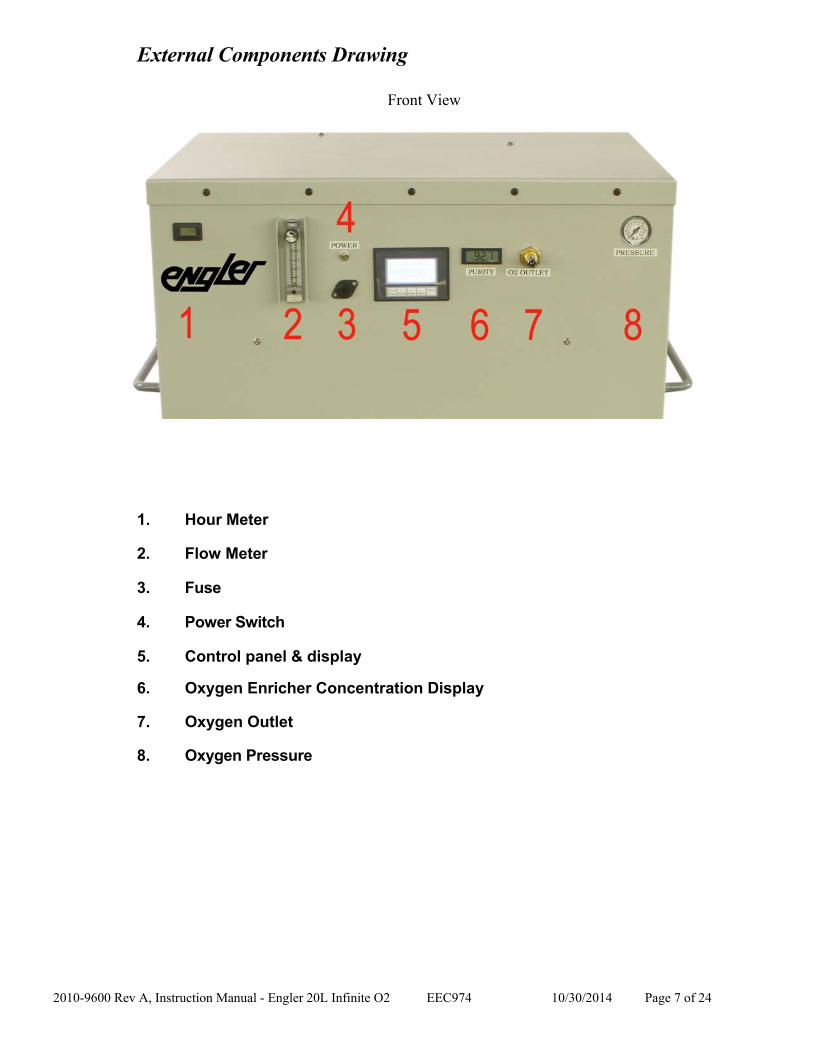
External Components Drawing
Front View
1. Hour Meter
2. Flow Meter
3. Fuse
4. Power Switch
5. Control panel & display
6. Oxygen Enricher Concentration Display
7. Oxygen Outlet
8. Oxygen Pressure

2010-9600 Rev A, Instruction Manual - Engler 20L Infinite O2 EEC974 10/30/2014 Page 8 of 24
External Components Drawing
Side Views Left Side Right Side 1 Handle 1. Handle 2. Filter Holder 2. Filter Holder 3. Power Cord 3. Lockable Caster 4. Lockable Caster

2010-9600 Rev A, Instruction Manual - Engler 20L Infinite O2 EEC974 10/30/2014 Page 9 of 24
External Components Description
Oxygen Concentration Display
This display shows concentration of the output oxygen.
Flow Meter This flow meter shows the output of the unit while it is operating. (It should remain full open).
Hour meter The hour meter shows how long the unit has been operating. This helps indicate when service intervals are due. It is resettable to identify time between service intervals, but the accumulated time cannot be modified.
Power Switch This switch controls power to machine. It is illuminated when the switch is in the ON position.
Unit Power Switches
These switches control each of the three units operating inside of the Oxygen generator. If a problem exists with one of the three units it may be turned off and the unit will continue to operate at a reduced output. These membrane switches are located on the display.
Power Cord The power cord used on 125 VAC / 60 Hz / 20 Amp electrical systems comes with a three-pronged grounded Euro plug.
Reset Button The reset button is actually a circuit breaker that opens if there is an electrical overload in the system. The main system reset is on the front of the machine.
Oxygen (O2 Outlet) The outlet fitting is a 1/4” female NPT pipe fitting.
Filter Holder The filter holders are located on each side of the unit and the filter elements should be cleaned every two weeks or sooner if in a dusty and dirty environment.

2010-9600 Rev A, Instruction Manual - Engler 20L Infinite O2 EEC974 10/30/2014 Page 10 of 24
Internal Components Drawing
Inside View
1. Modular Bed (3) 9. Compressor Capacitor (3)
2. Pressure Regulator (3) 10. OCSI Display Board
3. Circuit Board (3) 11. Oxygen Storage Tank
4. PLC 12. Inlet Resonator (2)
5. Air Inlet Filter (2) 13. Pressure Switch
6. Product Filter (3) 14. Terminal Block
7. Air Compressor (3) 15. Cooling Fan (3)
8. Heat Exchanger/Moisure Separator (3) 16. Solenoid Valve

2010-9600 Rev A, Instruction Manual - Engler 20L Infinite O2 EEC974 10/30/2014 Page 11 of 24
Internal Components Description
Modular Bed
These modular beds contain the molecular sieve that performs the air separation process, as well as the process control valves and oxygen storage tank. They are spring loaded to prevent settling and should never need to be opened. If the sieve becomes contaminated, the beds can be easily replaced.
Pressure Regulator The pressure regulator controls the pressure delivered to the oxygen outlet. It should be set in a way so that the pressure does not exceed 20 PSI (1.3 bar).
Circuit Board The circuit board controls the operation of the process control valves. While one valve coil is energized, the other is not. It also monitors the oxygen output to make sure it is at least 90% concentration.
Compressor Inlet Filter
The compressor inlet filter keeps dust and dirt from entering the compressor and needs to be changed twice a year in normal environments to maintain performance. In especially dirty and oily areas, it should be changed more often. Four times a year is recommended.
Air Compressor
The air compressor supplies the feed air to the sieve beds. It should work as designed for a minimum of 10,000 hours and may last 20,000 hours in some cases. It is suspended by four springs to dampen vibration that should not require replacement.
Heat Exchanger / Moisture Separator
The heat exchanger moisture separator delivers the feed air from the air compressor to the modular bed. Significant moisture removal occurs before the air enters the sieve beds, improving performance.
PLC The Programmable Logic Controller (PLC) provides the logic that operates the unit.
Terminal Strip Assembly
The terminal strip distributes electrical power as required to the compressors and control components of the machine.
Oxygen Purity Display The oxygen display board monitors the output of the unit and displays the purity on the front cabinet.
Oxygen Pressure Switch The oxygen pressure switch shuts the unit down after continuous operation when the unit is dead headed for a period of 15 minutes..
Oxygen Storage Tank The oxygen storage tank, provides a small buffer to allow the unit to operated smoothly on high demand applications, it provides product equal to approximately 30 seconds of operation.

2010-9600 Rev A, Instruction Manual - Engler 20L Infinite O2 EEC974 10/30/2014 Page 12 of 24
Process Flow Diagram

2010-9600 Rev A, Instruction Manual - Engler 20L Infinite O2 EEC974 10/30/2014 Page 13 of 24
Generator Process Flow Description
There are three independent subsystems providing oxygen to the outlet. Each one functions on it’s own, and if one system were to fail the other two will continue to provide oxygen but at a reduced output. In each system, once the incoming air is filtered and compressed in the Infinite O2 unit, it is directed into one of the two sieve beds, within the modular bed. As the air enters the bed, the nitrogen is adsorbed by the sieve and the oxygen passes through as product gas to the storage tank. Each bed produces oxygen until the sieve in that bed is saturated with nitrogen. When this occurs, the feed airflow is directed to the other bed, which continues the production process. While the second bed is producing oxygen, the first bed is releasing the nitrogen it adsorbed, into the atmosphere, under very low pressure through a waste gas muffler.
The oxygen product gas passes from the storage tank in the modular bed, through a factory set orifice, then, an OCSI monitor. If the concentration is above 90% then it will flow into a small receiver tank. This receiver tank serves as a reservoir for the oxygen prior to entering flow meter. The oxygen product gas is then delivered to the oxygen storage tank at up to 20 PSI (1.3 bar). From the storage tank the oxygen passes through a second OCSI monitor where a digital display of the concentration is produced. The system will automatically go on standby when the maximum pressure is reached and does not drop for 5 minutes.
OCSI Display Board: The OCSI board monitors the output of the machine to make sure the oxygen concentration is within acceptable conditions. Output of the machine will be up to 20 LPM of dry oxygen at 20 PSI (1.3 bar) discharge pressure. The board will use an ultrasonic sensor to determine the purity of the oxygen as it exits the sieve beds. The board will monitor the purity level and alarm if the purity falls below 90%.

2010-9600 Rev A, Instruction Manual - Engler 20L Infinite O2 EEC974 10/30/2014 Page 14 of 24
Unit Specifications Performance
Oxygen Volume/Pressure 42 SCFH @ 20 PSI 20 LPM or @ 1.3 bar
Oxygen Purity 93% (± 3%) [United States Pharmacopeia (USP) XXII oxygen 93% Monograph]
Oxygen Dew point - 60° F (-51° C)
Feed Air Requirement None, compressors included
Response Time Approximately 5 minutes to attain maximum purity after initial start-up or extended shut-down
Physical
Oxygen Outlet Fitting ¼” NPT Female or DISS
Sound Levels 68 dBA @ 1 m
Dimensions
36 x 22 x 42 in (W x D x H) 92 x 56 x 107 cm (W x D x H)
Weight 275 lb (125 kg)
Power Requirement
Standard 120VAC, 60 Hz, Single Phase 20 Amps each unit
Oxygen Flow Rate
42 SCFH @ 20 psi

2010-9600 Rev A, Instruction Manual - Engler 20L Infinite O2 EEC974 10/30/2014 Page 15 of 24
Safety Precautions
It is very important that you read the precautions below and make yourself familiar with the hazards of oxygen in general. While it can be handled and used very safely, it can also be mishandled or applied incorrectly causing dangerous situations.
Oxygen is a fire hazard. It can be very dangerous as it vigorously accelerates the burning of combustible materials. To avoid fire and / or the possibilities of an explosion, oil, grease or any other easily combustible materials must not be used on or near the oxygen generator. DO NOT SMOKE NEAR THE UNIT. The unit should be kept away from heat and flames. Individuals who have experience handling oxygen systems should become the designated operators of the oxygen generator within your facility.
In sensitive applications, it is important to have a backup supply of oxygen since the generator does not come with any reserve storage tank and requires electrical power to operate. Therefore, during power outages, oxygen will not be produced.
Do not use extension cords to bring power to the generator. The current drawn into the unit is high and could overheat some extension cords. It is also important to use only a properly grounded outlet.
High pressure oxygen may present a hazard. Always follow proper operating procedures, and open valves slowly. Rapid pressurization may result in personal injury. Safety glasses and hearing protection are required when venting oxygen under high pressure.
Ensure that the oxygen outlet stream is not directed toward anyone’s clothing. Oxygen will embed itself in the material and one spark or hot ash from a cigarette could ignite the clothing vigorously. All devices manufactured and / or sold by Engler Engineering Corporation are built and tested to approved standards. Any modification to the device, cables or hoses, initiated by others nullifies all warranty statements. Engler Engineering Corporation will not be held liable for any loss, damage, injury or death due to non-authorized service and / or improper installation and / or improper use or misuse of the device.

2010-9600 Rev A, Instruction Manual - Engler 20L Infinite O2 EEC974 10/30/2014 Page 16 of 24
Pre-Installation
Before installing the Engler Infinite O2 generator, it is necessary to consider the location, space available and power supply for the generator.
1) Locating the Infinite O2 System:
The oxygen generator should be located in an area that is indoors and remains between 40 F (5 C) and 100 F (38 C). Setting the machine outdoors or in an area that is not normally within this temperature range will void the Warranty.
There should be a distance of at least 8 in (20 cm) between the unit and any side wall in the room. It should also not be located any closer than 24 in. (60 cm) from the discharge of any other operating units. This ensures proper airflow into the generator and minimizes any restriction.
2) Space Available for the Infinite O2 System:
If the unit is going to be set up in a room that is small, (less than 2000 ft3or 56.6 m3), that room should be well ventilated (at least 8 air changes in the room per hour). The generator will be discharging nitrogen into the atmosphere of the room and a nitrogen build up could be dangerous to people entering the room. If the generator is placed in a small closet, the air in that closet will become enriched with nitrogen. As the generator continues to run, it would become more and more difficult for it to separate the oxygen from the air because oxygen will make up a smaller and smaller fraction of the air that is fed into the enricher.
3) Power Supply for the Infinite O2 System:
The oxygen generator should be positioned within 8 ft (2.2 m) of the electrical outlet that will power it. The reason for this is that the motor draws a large current during the first few seconds of start-up. It is also very important for this reason NOT to use any extension cords with the unit. They could overheat and melt, possibly causing a fire.

2010-9600 Rev A, Instruction Manual - Engler 20L Infinite O2 EEC974 10/30/2014 Page 17 of 24
Required Operating Conditions
Location of the Generator: The Infinite O2 System is intended for indoor use only. The enclosure meets NEMA 1 protection guidelines, which provides a degree of protection against dust and falling dirt.
Feed Air / Ambient Air Quality:
The life of any PSA oxygen generator is directly related to the air quality that is fed into it. Hot, humid, dirty, oily air deteriorates and degrades the performance of the molecular sieve. In order to preserve the effectiveness and extend the life of the generator, precautions must be taken to ensure that the air provided is cool, dry, clean, and oil-free. Changing the inlet air filter is a simple and easy way to provide the unit with some protection. It is advisable to position the unit in an air-conditioned, well-ventilated area. The room should also be free of toxic gases and high concentrations of hydrocarbons, especially carbon monoxide. Installation in humid, oily, dusty areas should be avoided as much as possible.
Ambient Air Temperature:
The machine is designed for use over a temperature range of 40 F to 104 F (5 C to 40 C). Since hot air has the ability to hold much more water in the form of humidity than cool air, operating the units in hot areas will reduce the effective life of the molecular sieve. Note: Operation outside of this temperature range will void the warranty.
Electrical Power:
The power for the control circuitry of the oxygen generator is a single-phase electrical supply of nominal 120 VAC and about 17 or 18 Amps at a frequency of 60 Hz. This equates to approximately 2000 W of power. A dedicated 20 Amp circuit is required for each Infinite O2 unit installed. Additionally, the unit must be connected to this circuit using only the supplied power cord, and without additional extension cords.
Positioning:
The unit must be operated in an upright position only, with no obstruction blocking airflow around the unit.

2010-9600 Rev A, Instruction Manual - Engler 20L Infinite O2 EEC974 10/30/2014 Page 18 of 24
Set-up, Installation, and Operation
Although every Infinite O2 unit is thoroughly tested and checked before it is shipped from our facility, the following checks are necessary to ensure that none of the internal components have been damaged in shipment. This check should take less than five minutes to perform. (Refer to ‘Initial Inspection’ on Page 2 before reading the instructions below)
Make a visual inspection of the machine and make sure all parts are properly attached. (Refer to ‘Components’ section)
Connect the unit into a dedicated electrical outlet. A receptacle plug of local configuration will need to be attached first if the supplied NEMA 5-20 (125V) is not acceptable. Please note that this system will only work with nominal 120 VAC 60 Hz.
To test the Infinite O2 Generator unit, turn the Power Switch to the ON (up) position and make sure that the Display unit illuminates. After a few seconds the hour glass indicator disappears and the unit will begin to operate. Each of the three units should cycle on, one at a time. The generator will begin operating, and after about one minute the Oxygen output will open.
Listen for the sound of the three compressors to start operating one at a time (staged in to reduce start-up current draw), if you do not hear it within ten minutes, shut the machine down immediately and call EEC for assistance.
Turn the power switch off after testing.
The oxygen flow meter should indicate a flow increase after each of the individual units cycle on and meets minimum purity requirements. If this does not occur, check to make sure that none of the hose connections have come loose. If the trouble persists, Call the EEC Technical Service Department at +1(800))445-8581.

2010-9600 Rev A, Instruction Manual - Engler 20L Infinite O2 EEC974 10/30/2014 Page 19 of 24
Troubleshooting Guide
Problem Sign Cause Solution
Machine not starting
Machine not plugged in Machine not turned on No power to the machine
Circuit breaker has tripped
Compressor under pressure Loose wire
Ensure that machine is plugged in. Ensure that switch is in the ON position. Ensure that there is power supply to the machine.
Push in the reset button on theright hand side of the cabinet.
Remove the head pressure that exists in the compressor outlet stream.
Check that all wiring connections are secure.
Pressure Switch not Working
Machine not turning ON / OFF at target press res
Faulty switch Remove switch and return for replacement.
Low Oxygen Pressure This may be a result of a leak in the system.
Use a leak testing solution to locate and repair any leaks.
Oxygen purity has fallen below acceptable limits
This may be a result of a leak in the system.
Beds Are Hydrated
Dirty Filters
Use a leak testing solution to locate and repair any air leaks.
Replace Beds
Replace Filters

2010-9600 Rev A, Instruction Manual - Engler 20L Infinite O2 EEC974 10/30/2014 Page 20 of 24
Preventive Maintenance Air Filter Cleaning
The air filter elements should be removed and cleaned in soapy water every two weeks or 20 hours of operation to reduce the dust and dirt contamination inside of the unit.
Compressor Filter Element Replacement:
The air filter element provided with the Infinite O2 system must be replaced every six (6) months on an average and more frequently in dusty environments. This element helps to maintain the quality of the feed air supply, preserve the molecular sieve, and extend the life of the air compressor.
Failure to replace the filter element on schedule will invalidate the warranty.
Cabinet & Power Cord:
The cabinet and power cord should be wiped down occasionally with a sponge or clean rag and some soapy water. Avoid the use of ammonia or other strong chemical based cleaning solvents. This prevents dust and dirt from building up on the machine.
Air Compressor:
The air compressors are a very important part of your oxygen generating system. In addition to changing the air filter element, maintenance is relatively simple. The fans on either end should remain free of debris / dust. The air compressors should last five (5) to six (6) years or longer under normal operating conditions. Eventually, however, it will need to be rebuilt or replaced. Oxygen purity and flow rate along with feed air pressure delivered to the sieve beds will all be indicators that the air compressors has expended its life. Replacement in the field is possible, but returning the unit to Engler Engineering Corp. is recommended.
OCSI Display Board
The OCSI board should never require calibration and cannot be calibrated in the field. Calibration can be verified periodically if needed. Remove the back of the unit and disconnect the hoses from the sensor on the large board. Supply the board with calibration quality oxygen (99.99%) and check the display. If the display reads 90.2% +/- 3% then it is within the calibration specifications. If it is outside that range it should be replaced. Contact EEC for further instructions.
Notice Using the Engler Infinite O2 generator / storage system in any manner inconsistent with it’s labeling will void any warranty or liability from Engler Engineering Corp. Engler Engineering Corp. will not be responsible for any malfunction, injury or death due to unauthorized modification or alteration of any part or component. Only parts or assemblies supplied by Engler Engineering are permitted as acceptable replacement parts.
2010-9600 Rev A, Instruction Manual - Engler 20L Infinite O2 EEC974 10/30/2014 Page 21 of 24
Technical Service Assistance
It is our intention to provide complete customer satisfaction. This manual is one way in which we hope to provide you with technical assistance. If you do not find what you need in this manual or you have other questions about this equipment, please feel free to contact us directly. We look forward to serving your oxygen needs and invite your inquiries. We will respond to you as promptly as possible.
You can reach EEC through the following means:
By Telephone (Outside the United States): Your local International Access Code (usually 0 or 00), followed by the Country Code for the U.S. which is (1), followed by our Area Code and Number (305) 688-8581 Domestic Toll Free: 800-445-8581 By Fax (Within or outside the United States): +1(305) 685-7671 By E-Mail or Website: [email protected] http://www.englerusa.com
By Mail: Engler Engineering Corp. 1099 East 47 Street Hialeah, Florida 33013 USA
By UPS, FedEx or Common Carrier: (Address to return shipments) Engler Engineering Corp. 1099 East 47 Street Hialeah, Florida 33013 USA

2010-9600 Rev A, Instruction Manual - Engler 20L Infinite O2 EEC974 10/30/2014 Page 22 of 24
Appendix A Spare Parts List
PART NAME PART NUMBER QUANTITY
Power Cord 12-3 (125V) NEMA 5-20 9600-1058 1
Strain Relief for Power Cord 9600-1080 1
Hour meter – Re-settable 8400-5028 1
Master On - Off Switch 9251-1809 1
20 A Fuse (115V) 9600-1066 1
15 A Thermal O / L button (230V) 9600-1023 1
Pressure Switch 9600-1083 1
Programmable Logic Controller 9600-1500 1
HMI Display Unit 9600-1505 1
Subsystem OCSI Board 8400-1310 3
Main OCSI system with Display 9251-1810 1
24VDC Power Supply Board 9600-1510 1
24VDC Control Relay 9600-1011 3
Modular Bed Control Valve 8400-1200 3
Inline Check Valves 9600-1081 2
Oxygen Pressure Regulator 8400-2060 3
Compressor Assembly (115 VAC, 60 Hz) 9251-1615 3
Thomas Compressor Rebuild Kit 7355-3670
1/8" NPT 3-Way Isolation Valve 24VDC 9251-1804 3
1/4" OD Blue Oxygen Polyurethane Tubing - Per Foot 7854-6109
1/4" ID Braid Reinforced PVC Tubing - Per Foot 7854-6105
3/8" OD Green Nylon Tubing - Per Foot (Low Temp Air) 7854-6107
PART NAME PART NUMBER QUANTITY
3/8” OD Clear FEP Tubing - Per Foot (High Temp Air) 7854-6106

2010-9600 Rev A, Instruction Manual - Engler 20L Infinite O2 EEC974 10/30/2014 Page 23 of 24
Inlet Air Filter 9600-1053 2
Exhaust Fan 115V V 9300-1024 3
Exhaust Fan 115 V 9300-1023 3
Air Compressor filter (Change every 6 months) 9600-1012 2
Compressor Capacitor (115V) 9251-1647 3
Flow meter 9600-1026 1
Product Filter 9250-1053 3
Caster 9600-1016 4
Moisture Separator 9251-1911 3
Compressor Outlet Fitting 9251-1052 3
Moisture Separator Inlet Fitting 9250-1163 3
Moisture Separator Outlet Fitting 9250-1167 3
Inline Orifice 9600-1018 3
Front Panel Gauge 9600-1082 1
Replacement Set of Sieve Beds 8400-8021 3
Manual-Available Free on Website 2010-9600

2010-9600 Rev A, Instruction Manual - Engler 20L Infinite O2 EEC974 10/30/2014 Page 24 of 24
Appendix B Maintenance Log
Date Part Reason for Maintenance Authorized Service Technician Signature