Installation, operation, and maintenance instructions for ... · PDF filePVG-2014-10-ENG...
31
PVG-2014-10-ENG Original document language: English Installation, operation, and maintenance instructions for Flowrox PVG valves DN50 – 250 These instructions must be read carefully and understood prior to the installation, use, and servicing of this product. NOTE FLOWROX OY P.O. Box 338 FI-53101 Lappeenranta, Finland Tel. +358 (0)201 113 311 Fax +358 (0)201 113 300 E-mail: [email protected] www.flowrox.com
Transcript of Installation, operation, and maintenance instructions for ... · PDF filePVG-2014-10-ENG...

PVG-2014-10-ENG
Original document language: English
Installation, operation, and maintenance
instructions for Flowrox
PVG valves DN50 – 250
These instructions must be read carefully and
understood prior to the installation, use, and servicing
of this product.
N O T E
FLOWROX OY
P.O. Box 338
FI-53101 Lappeenranta, Finland
Tel. +358 (0)201 113 311 Fax +358 (0)201 113 300
E-mail: [email protected]
www.flowrox.com

DISCLAIMER
ALL INTELLECTUAL PROPERTY RIGHTS TO THIS MANUAL (“MANUAL”) BELONG TO FLOWROX OY
(”FLOWROX”) WHICH REMAINS THE SOLE OWNER OF THESE RIGHTS. OWNERSHIP OF THESE RIGHTS
ARE NOT TRANSFERRED FROM FLOWROX TO ANYONE IN CONNECTION WITH THIS MANUAL. THIS
MANUAL IS INTENDED TO BE USED ONLY BY FLOWROX´S CUSTOMER AND EXCLUSIVELY FOR THE
PURPOSES OF THE AGREEMENT UNDER WHICH THIS MANUAL IS DELIVERED TO FLOWROX´S
CUSTOMER. WITHOUT THE PRIOR WRITTEN EXPLICIT CONCENT FROM FLOWROX, NO PART OF THIS
MANUAL SHALL BE USED, REPRODUCED, COPIED, TRANSLATED,CONVERTED, ADAPTED, STORED IN
A RETRIEVAL SYSTEM , COMMUNICATED OR TRANSMITTED BY ANY MEANS, OR FOR ANY
COMMERCIAL OR OTHER PURPOSES, INCLUDING , BUT NOT LIMITED TO, SALE, RESALE, LICENS,
RENT OR LEASE.
THIS MANUAL PROVIDES INSTRUCTIONS TO CARRY OUT CERTAIN ACTIVITIES AND IS DESIGNED AND
MEANT TO GUIDE AND ASSIST PROFESSIONAL AND PROPERLY TRAINED EXPERTS IN PERFORMING
THEIR FUNCTIONS. EVERYONE MUST BECOME FAMILIAR WITH ALL INSTRTUCTIONS IN THIS MANUAL
BEFORE ANY INSTALLATION, USE, MAINTENANCE, REPAIR OR ANY OTHER ACTIONS OF THE
RESPECTIVE GOODS AND/OR SERVICES WHICH THIS MANUAL APPLIES TO. ALL INSTRUCTIONS MUST
BE FOLLOWED CAREFULLY. HOWEVER, OBSERVANCE OF ANY PART OF THE INSTRUCTIONS
PRESENTED IN THIS MANUAL MAY BE OMITTED IN EVENT WHEN IT IS REQUIRED OR ALLOWED BY
LAW
FLOWROX HAS TAKEN EVERY CARE IN THE PREPARATION OF THE CONTENT OF THIS MANUAL, BUT
DOES NOT MAKE ANY REPRESENTATIONS, WARRANTIES OR GUARANTEES OR, EXPRESS OR IMPLIED,
AS TO THE ACCURACY OR COMPLETENESS OF THIS MANUAL. ALL USERS MUST UNDERSTAND AND BE
AWARE THAT UPDATES AND AMENDMENTS WILL BE MADE FROM TIME TO TIME TO THIS MANUAL.
ALL USERS ARE OBLIGATED TO FIND OUT AND DETERMINE WHETHER THERE HAVE BEEN ANY
APPLICABLE UPDATES OR AMENDMENTS TO THIS MANUAL. NEITHER FLOWROX NOR ANY OF ITS
DIRECTORS, OFFICERS, EMPLOYEES, SUBCONTRACTORS, SUB-SUPPLIERS, REPRESENTATIVES OR
AGENTS SHALL BE LIABLE IN CONTRACT, TORT OR IN ANY OTHER MANNER WHATSOEVER TO ANY
PERSON FOR ANY LOSS, DAMAGE, INJURY, DEATH, LIABILITY, COST OR EXPENSE OF ANY NATURE,
INCLUDING WITHOUT LIMITATION INDIRECT, INCIDENTAL, SPECIAL, CONSEQUENTIAL, PUNITIVE OR
DIRECT DAMAGES AND/OR LOSSES ARISING OUT OF OR IN CONNECTION WITH THE CREATION,
DELIVERY, POSSESSION AND/OR USE OF THIS MANUAL. HOWEVER, NOTHING IN THIS PARAGRAPH IS
DEEMED TO EXCLUDE OR RESTRICT ANY LIABILITY WHICH CANNOT BY MANDATORY LAW BE
EXCLUDED.
FLOWROX IS THE TRADEMARK OF FLOWROX OY REGISTERED IN FINLAND AND IN OTHER
COUNTRIES. ALL OTHER TRADEMARKS, LOGOS, BRANDS AND MARKS DISPLAYED IN THIS MANUAL
ARE PROPERTY OF THE RESPECTIVE OWNERS UNLESS STATED OTHERWISE.
Copyright © 2014 Flowrox Oy. All rights reserved.

TABLE OF CONTENTS
1 DIRECTIVE CONFORMANCE DECLARATIONS ............................................ 4
1.1 General safety instructions ........................................................................ 5
2 INTRODUCTION .............................................................................. 6
2.1 Applications and purpose of use ................................................................. 6 2.1.1 Restrictions on use for PVG valves ............................................................. 6 2.1.2 Using the valve in explosive conditions ....................................................... 6
2.2 General description ................................................................................. 7 2.2.1 Principle of operation ............................................................................ 7
2.2.2 Mechanical structure ............................................................................. 8 2.3 Technical data ...................................................................................... 10
2.3.1 Product identification ........................................................................... 10 2.3.2 Actuators .......................................................................................... 11
3 TRANSPORTATION, STORAGE AND LIFTING .......................................... 12
4 INSTALLATION ............................................................................. 14
4.1 General ............................................................................................... 14 4.2 Flow direction, support, and valve position ................................................. 15 4.3 Valve installation .................................................................................. 15
5 VALVE OPERATION........................................................................ 17
5.1 Commissioning and decommissioning ......................................................... 17
6 SERVICING AND MAINTENANCE ......................................................... 18
6.1 General maintenance and checks .............................................................. 18 6.1.1 Scheduled maintenance ........................................................................ 19
6.1.2 Spare parts ........................................................................................ 19 6.2 Changing the sleeve ............................................................................... 20
6.2.1 Removing the sleeve ............................................................................ 20 6.2.2 Installing the sleeve ............................................................................. 22
6.3 Testing and adjusting the valve stroke ....................................................... 25 6.3.1 Adjusting the pneumatic actuator stroke ................................................... 25
6.4 Troubleshooting .................................................................................... 29 Appendix A: Main dimensions of valves ................................................................ 30

4
© 2014 Flowrox Oy. All rights reserved.
Contents are subject to change without notice.
PVG-2014-10-ENG
1 DIRECTIVE CONFORMANCE DECLARATIONS
FLOWROX OY
Marssitie 1
P.O. Box 338
FI-53101 Lappeenranta
Finland
Tel. +358 201 113 311
hereby declares that the Flowrox PVG pinch valve delivered
complies with the following applicable regulations:
Pressure Equipment Directive 97/23/EC (PED):
Valve size DN 250 (PN 10) and smaller according to article 3, paragraph 3 (SEP), no CE marking for
conformity with PED.
European Union Machinery Directive 2006/42/EC and
Finnish Government Decree on Machine Safety, 400/2008, Machine Decree (koneasetus):
Annex IIB “partly complete machine”. No conformity with directive when valve is actuated manually.
Atex Directive 94/9/EC:
Conformity to directive declared only if Ex and CE are marked on valve nameplate. In that case a
separate Atex declaration is supplied.
Do not operate valve before conformity to machine directive 2006/42/EC has been declared for the
complete machine (pipeline) to what the valve is installed as a partly complete machine. Follow the
valve installation instructions in this manual. Conformance declarations for accessories (solenoid valve,
limit switches etc.) and actuators are supplied separately in component documentation. Risk analysis
responsible employee at Flowrox Oy is Jarmo Partanen.
On behalf of Flowrox Oy
In Lappeenranta, 19 July 2013
Heikki Hyttinen
President and CEO

5
© 2014 Flowrox Oy. All rights reserved.
Contents are subject to change without notice.
PVG-2014-10-ENG
1.1 General safety instructions
The symbols in Table 1 are used in this manual to highlight the parts requiring particular
attention.
Table 1.Warning and safety signs.
Symbol Description
Risk to personal safety:
Neglecting the safety measures can cause serious
injury or death.
Machinery or environmental risk:
Incorrect maintenance or operation of the product
can harm the environment or the product.
Read the operation and maintenance instructions:
Read and understand the operation and
maintenance instructions before using the product.
Prevent accidents and ensure the valve’s appropriate operation by complying with the
installation, safety, and maintenance instructions in this manual. Installation and
maintenance of the valve must be carried out by persons with appropriate training. Electrical
installation work of the actuator must be performed by a qualified electrician.
Access to the IOM-manual must be guaranteed at all times at the place of operation of the
valve. It is required to observe the IOM-manual in all work tasks for the valve.
Use personal protective equipment when performing any checks or maintenance operation for
the valve (goggles, helmet, clothing and gloves). Always follow the factory safety regulations.
In case of any discrepancies between translations, the English version shall prevail.
DANGER
WARNING
N O T E

6
© 2014 Flowrox Oy. All rights reserved.
Contents are subject to change without notice.
PVG-2014-10-ENG
2 INTRODUCTION
2.1 Applications and purpose of use
Flowrox PVG is made for processes involving pressure resistance, abrasion, corrosion and
aggressive slurries. In open position, the PVG valve is at full bore with no flow restrictions.
The core of the PVG valve is an elastic sleeve, which is the only part in contact with the
process medium. Designed to withstand wear, corrosion and chemicals, Flowrox sleeves
guarantee non-clogging, trouble free operation and extended lifetime. The sleeves are bubble
tight and easily replaceable if necessary.
2.1.1 Restrictions on use for PVG valves
The valve temperature and pressure range must not be exceeded. The temperature ranges
are given in Table 2 for standard sleeve materials. Check the pressure class from the valve
type plate. Do not use higher pipeline pressure than rated for the valve.
Table 2. Temperature ranges for PVG valves.
Sleeve material SBRT EPDM
Min valve operating temperature (°C)
-40 -40
Max valve operating temperature (°C)
+110 +120
2.1.2 Using the valve in explosive conditions
This valve type is not designed for Ex-areas.
For use in explosive conditions the valve must have the required Ex-classification and the
grounding cables must be connected to earth. Check actuator, solenoid valve, and limit
switch documentation for more information about operation in explosive conditions.

7
© 2014 Flowrox Oy. All rights reserved.
Contents are subject to change without notice.
PVG-2014-10-ENG
2.2 General description
2.2.1 Principle of operation
Flowrox PVG valve is built with a cast body and a rubber sleeve as a standard structure.
Removable sleeve means no metal parts are in contact with the process medium.
In the open position the valve provides full bore through which the medium can travel. There
are some structural differences between valve sizes, but the main components are shown in
Figure 1.
Closing the valve forces the actuator side of the sleeve progressively towards the other side
until it reaches the fully closed position. When the valve is fully closed, the sleeve is
squeezed between the pusher on actuator and valve body, effectively sealing and completely
containing the line pressure.
Figure 1.Main components of PVG valve with manual actuator.
Part Description Part Description
1 Body 5 Threaded bushing
2 Sleeve 6 Hand Wheel
3 Pusher 7 Bellows
4 Stem

8
© 2014 Flowrox Oy. All rights reserved.
Contents are subject to change without notice.
PVG-2014-10-ENG
The valve must not be used to throttle the flow as
this will lead to premature failure of the sleeve.
This valve is intended for on-off operation only.
2.2.2 Mechanical structure
The alternative actuators are displayed in Figure 2.
An exploded view of PVG valve with manual actuator is shown in Figure 3 and valve part list in
Table 4.
Figure 2.Alternative actuators.
Table 3. PVG valve actuator options.
Part Description
M Manual actuator
A Pneumatic actuator
E Electric actuator
WARNING

9
© 2014 Flowrox Oy. All rights reserved.
Contents are subject to change without notice.
PVG-2014-10-ENG
Table 4. Part list of PVG valve with manual actuator.
Part Description Part Description
1 Valve body 9 Cable tie
2 Sleeve 10 Bellows
3 Pusher 11 Washer
4 Stem 12 Hex screw
5 Pusher plate 13 Nut
6 Hex socket screw 14 Hand wheel
7 Thread bushing 15 Keen pin
8 Bellows bushing
Figure 3.Exploded view of PVG valve with manual actuator.

10
© 2014 Flowrox Oy. All rights reserved.
Contents are subject to change without notice.
PVG-2014-10-ENG
2.3 Technical data
2.3.1 Product identification
Flowrox valve type plate is shown in Figure 4.
1. Valve type (see Table 5)
2. Serial number (year, order number,
series size, individual valve number)
3. Customer tag number etc.
4. Nominal diameter, pressure class
Figure 4.Example of valve type plate.
Table 5. PVG valve model key table.
Type Size
(DN) Actuator
Pressure
class (PN) -
Flange
drilling
Body
material -
Sleeve
material - Auxiliaries
PVG =
Flowrox
Pinch
valve
50-250 M = manual
A = pneumatic
E = electric
4 = 4 bar
6 = 6 bar
10 = 10 bar
2 = DIN PN10
6 = ANSI150
9 = other
0 = Cast iron
SBRT = Styrene
Butadiene
rubber
EPDM = ethylene
propylene diene
monomer
Z1 = solenoid
valve, 24V DC
Z2 = solenoid
valve, 220V,
50/60 Hz
Z3 = solenoid
valve, 110V,
50/60 Hz
Example: PVG150M10-20-SBRT
The main dimensions and weight are given in Appendix A: Main dimensions of valves.

11
© 2014 Flowrox Oy. All rights reserved.
Contents are subject to change without notice.
PVG-2014-10-ENG
2.3.2 Actuators
Standard actuators:
● Manual
● Pneumatic
● Electric
Manual valves are closed by turning the hand wheel clockwise.
Pneumatic actuators are with a fixed stroke and do not require external controls. The
minimum supply pressure for pneumatically operated valves is 6 bars. Use correct sized
pneumatic hoses to ensure sufficient air flow.
Air must be clean and dry and comply with ISO 8573-1:2001 Class 3.
Pneumatic actuator noise level may exceed 85 dB and it is recommended to use ear
protectors when working near the valve.
Electric actuators have open/close limit switches preset at the factory. A separate instruction
from the actuator manufacturer is always included in the shipment.
Please consult the manufacturer’s instructions on actuator requirements or/and limitations. If
actuator is changed or valve needs adjustment, follow the Maintenance instructions.

12
© 2014 Flowrox Oy. All rights reserved.
Contents are subject to change without notice.
PVG-2014-10-ENG
3 TRANSPORTATION, STORAGE AND LIFTING
Check and document any damages in the valve packages or valves. Contact the transportation
company in case of damage. When new or unused valves are sitting idle for long periods, the
following procedures should be complied with:
1. Prior to storage, thoroughly drain valves of any and all water.
2. Indoor storage is required. For unfavourable environment, cover the equipment with
protective tarpaulin that will allow proper air circulation.
3. Protect the equipment from temperature and humidity extremes and exposure to
excessive dust, moisture, vibration and sunlight.
4. It is preferred to store valves in the open position.
5. Avoid dirt and/or moisture contamination of the stem (threaded rod).
6. Ensure pneumatic cylinder actuators have appropriate pipe plugs installed in the
respective supply ports to prevent contamination of the cylinders.
7. Protect valve sleeves from heat, sunlight and exposure to ozone.
8. Cover the flange openings.
9. Do not store any objects on top of the rubber sleeves.
10. Follow the actuator instructions for storage.
11. Before start-up clean the valve.
When storing used valves, wash the valve with fresh water and follow the steps above. For
storage periods greater than 36 months, please contact Flowrox as the rubber parts need to
be changed before use.
Lifting equipment must be used for valves weighing
over 25kg.
DANGER

13
© 2014 Flowrox Oy. All rights reserved.
Contents are subject to change without notice.
PVG-2014-10-ENG
Lift the valves securely from the body (part 1 in Mechanical structure) and use existing lifting
eyes when available. When lifting eyes are not available use soft straps to lift valve as shown
in Figure 5.Valve lifting examples.
Figure 5.Valve lifting examples.
Do not attach lifting equipment to the valve bore or actuator as they can be damaged.
For valve dimensions and weight, refer to Appendix A.

14
© 2014 Flowrox Oy. All rights reserved.
Contents are subject to change without notice.
PVG-2014-10-ENG
4 INSTALLATION
Do not put your hands or fingers inside the sleeve
when the valve cycles.
Do not use higher pressure than rated for the valve.
Higher pressures can cause serious damage to the
valve or harm to operating personnel.
Do not energize the actuator before the valve is
properly attached to the pipeline.
4.1 General
Flowrox valves are normally delivered fully assembled and ready for use. The valve can be
installed either way in terms of flow direction. Only personnel with appropriate training are
allowed to install the valves. If the valve is delivered without an actuator or accessories, they
must be installed in accordance with the manufacturer’s instructions.
Flowrox valves have connections with DIN or ANSI bolt drillings as standard design, but some
other drillings are also available on request.
Reserve enough space for safe installation and maintenance. See Appendix A for valve
dimensions.
DANGER
DANGER
DANGER

15
© 2014 Flowrox Oy. All rights reserved.
Contents are subject to change without notice.
PVG-2014-10-ENG
4.2 Flow direction, support, and valve position
Do not step on a valve installed in horizontal or
angled position.
The valve does not have an intended flow direction; therefore it can be installed either way
in the pipeline.
Proper pipe support must be placed on either side of the valve to support the weight. The
valve must never be used to support the pipes.
The valve can be installed in any position.
4.3 Valve installation
At least the following must be ensured before valve installation:
● The pipeline is isolated from the process and there is no pressure in it.
● The pipeline is empty, clean, and cooled down.
● The pipeline flanges are parallel, concentric and with correct distance.
● The flange connection bolts size is correct. Shown in Table 6. PN10 flange bolt
nominal diameter and compression values for rubber sleeve flanges.
● The valve is in OPEN position.
1. Disconnect automatic actuator from power supply if connected.
2. Lift the valve on place with appropriate lifting equipment.
3. Tighten the flange bolts evenly in a crosswise sequence as shown in Figure 7. Flange bolt tightening example. Recommended compression for the rubber sleeve flange is shown in Table 6. PN10 flange bolt nominal diameter and compression values for rubber sleeve flanges.
4. Connect automatic actuator to power supply.
5. Check that all connections have been fastened and the actuator is connected correctly.
6. Run a few open/close cycles without pressure in pipeline. Refer to Troubleshooting if the valve does not operate smoothly or without extra force.
DANGER

16
© 2014 Flowrox Oy. All rights reserved.
Contents are subject to change without notice.
PVG-2014-10-ENG
Table 6. PN10 flange bolt nominal diameter and compression values for rubber sleeve flanges.
Valve size (DN)
Recommended compression for rubber sleeve flange (mm)
DIN Bolt nominal diameter
ANSI150 Bolt nominal
diameter
50 2-3 M16 5/8”-11 UNC
80 2-3 M16 5/8”-11 UNC
100 3-4 M16 5/8”-11 UNC
150 3-4 M20 3/4”-10 UNC
200 4-5 M20 3/4”-10 UNC
250 4-5 M20 7/8”-9 UNC
Figure 6. Compression of the sleeve rubber flange.
A = Uncompressed rubber sleeve flange [mm]
B = compressed rubber sleeve flange [mm]
(A – B) = Recommended compression [mm], shown in Table 6. PN10 flange bolt nominal diameter and compression values for rubber sleeve flanges.
Figure 7. Flange bolt tightening example.

17
© 2014 Flowrox Oy. All rights reserved.
Contents are subject to change without notice.
PVG-2014-10-ENG
5 VALVE OPERATION
5.1 Commissioning and decommissioning
Before the valve is operated within the pipeline, ensure that it has been installed in
accordance with this manual and applicable safety regulations.
The following must also be ensured:
● Parameters on the type plate are suitable for the process and environment
● The valve is used for the purpose specified at the time of sales
● Required accessories are installed if applicable
● Possible explosive conditions have been taken into account
When a valve is decommissioned, dispose the valve parts and electric/pneumatic devices
(actuators) according to the local regulations and the instructions given by the part or device
manufacturer.
Collect and dispose dangerous process media, so that people and environment are not
endangered. Follow the local regulations.

18
© 2014 Flowrox Oy. All rights reserved.
Contents are subject to change without notice.
PVG-2014-10-ENG
6 SERVICING AND MAINTENANCE
6.1 General maintenance and checks
Depressurise, empty and cool down the valve before
any maintenance work. Valve surface can be hot.
Isolate the valve completely from the process and
follow the factory safety regulations.
Crush hazard. De-energize actuators before
maintenance.
Do not step on a valve installed in horizontal or
angled position.
Only personnel with appropriate training are allowed to service the valves. For actuator
service instructions consult the manufacturer’s documentation supplied with the valve.
Check the condition of the valve regularly. When the valve is tight and it actuates flawlessly,
periodic inspection is the only mandatory maintenance task. Do not neglect it as sleeves wear
over time depending on conditions and process.
DANGER
DANGER
DANGER

19
© 2014 Flowrox Oy. All rights reserved.
Contents are subject to change without notice.
PVG-2014-10-ENG
6.1.1 Scheduled maintenance
Include the valves in your factory maintenance program. Maintenance tasks and service
intervals are offered as a guideline in Table 7. Schedules will vary with applications.
Table 7. Maintenance schedule.
Maintenance task Frequency & advice
Do a leakage inspection Regularly. Refer to Troubleshooting.
Run an open/close cycle Suggested once a month for smooth and reliable operation.
Examine the valve for erosion and wear Every six months.
For electric actuator maintenance schedule refer to manufacturer’s instructions.
6.1.2 Spare parts
To ensure correct and quick delivery of spare parts, the order must contain at least the
following information:
● Valve type number as in type plate (example: PVG150M10-20-SBRT)
● Spare part name and quantity (example: Sleeve, 1 piece)
You can order the spare parts from Flowrox offices, distributors or agents. Contact
information is available at http://www.flowrox.com
It is recommended to keep one sleeve as a spare part at your factory warehouse. For part
numbers refer to Mechanical structure.
Information regarding wearing components that are not supplied as Flowrox spare parts are
also in Mechanical structure.

20
© 2014 Flowrox Oy. All rights reserved.
Contents are subject to change without notice.
PVG-2014-10-ENG
6.2 Changing the sleeve
To change the sleeve, the valve needs to be removed from the pipeline. Refer to Valve
dismantling if further service is required as well. Part numbers refer to Mechanical structure.
Do not disconnect a pressurized valve from the
pipeline in any case!
6.2.1 Removing the sleeve
1. Operate the valve to fully OPEN position.
2. Depressurise and drain the pipeline according to mill specific orders.
3. Disconnect automatic (electric or pneumatic) actuator from power supply to prevent
injuries.
4. Remove the flange connection bolts and lift the valve to a suitable working surface.
Use lifting equipment on valves weighing over 25kg.
5. Remove the valve body fasteners (parts 11-13) and lift both body halves (part 1) away.
Figure 8. Removing the valve body parts.
DANGER

21
© 2014 Flowrox Oy. All rights reserved.
Contents are subject to change without notice.
PVG-2014-10-ENG
6. Loosen the pusher screws (part 6) to be able to release the opening tags on the sleeve.
Figure 9. Releasing the opening tags.
7. Detach the sleeve (part 2) from the pusher (part 3).
Figure 10. Removing the sleeve.
8. Inspect the body halves for visible damage.
9. Check if the pusher (part 3) is damaged and needs to be replaced.
10. Clean the valve body halves.
22
© 2014 Flowrox Oy. All rights reserved.
Contents are subject to change without notice.
PVG-2014-10-ENG
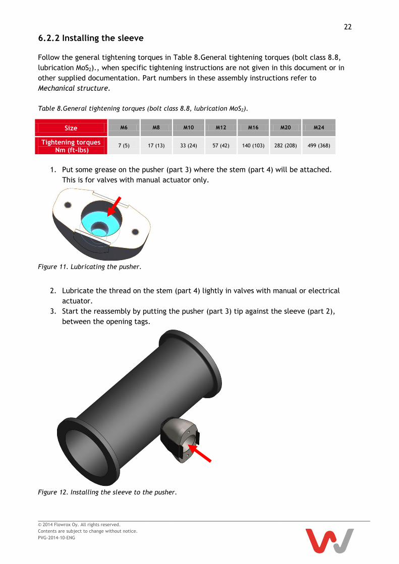
6.2.2 Installing the sleeve
Follow the general tightening torques in Table 8.General tightening torques (bolt class 8.8,
lubrication MoS2)., when specific tightening instructions are not given in this document or in
other supplied documentation. Part numbers in these assembly instructions refer to
Mechanical structure.
Table 8.General tightening torques (bolt class 8.8, lubrication MoS2).
Size M6 M8 M10 M12 M16 M20 M24
Tightening torques Nm (ft-lbs)
7 (5) 17 (13) 33 (24) 57 (42) 140 (103) 282 (208) 499 (368)
1. Put some grease on the pusher (part 3) where the stem (part 4) will be attached.
This is for valves with manual actuator only.
Figure 11. Lubricating the pusher.
2. Lubricate the thread on the stem (part 4) lightly in valves with manual or electrical
actuator.
3. Start the reassembly by putting the pusher (part 3) tip against the sleeve (part 2),
between the opening tags.
Figure 12. Installing the sleeve to the pusher.

23
© 2014 Flowrox Oy. All rights reserved.
Contents are subject to change without notice.
PVG-2014-10-ENG
4. Install the opening tags through the slots in the pusher plate (part 5).
Figure 13. Installing the opening tags to pusher plate.
5. Pull the opening tags finger tight and fasten the pusher plate with hex screws (part 6).
6. Check that the tags follow the shape of the pusher (part 3).
7. Cut away the extra length of the tags.
Figure 14. Fastening the pusher plate screws.

24
© 2014 Flowrox Oy. All rights reserved.
Contents are subject to change without notice.
PVG-2014-10-ENG
8. Lift the body halves (1) back and install the fasteners (parts 11-13).
Figure 15. Fastening the body halves to the valve.
9. Leave the valve to OPEN position until it is installed and follow the storage
instructions if the valve is placed in stock.

25
© 2014 Flowrox Oy. All rights reserved.
Contents are subject to change without notice.
PVG-2014-10-ENG
6.3 Testing and adjusting the valve stroke
Only personnel with appropriate training are allowed to energize the valves. Check and adjust
the valve stroke if you dismantle the valve or assemble a pneumatic actuator. This is not
needed with manual actuators. Refer to the electrical actuator documentation for specific
stroke adjustment instructions.
Crush hazard. Keep your hands and feet clear of
moving parts.
6.3.1 Adjusting the pneumatic actuator stroke
1. Assemble the valve according to the assembly instructions.
2. Loosen the actuator lower and upper fastener nuts.
Figure 16. Pneumatic actuator lower and upper fastener nuts.
3. Connect the actuator to power source and stroke the valve to fully CLOSED position.
DANGER

26
© 2014 Flowrox Oy. All rights reserved.
Contents are subject to change without notice.
PVG-2014-10-ENG
4. Tighten the lower actuator nuts (1) until strip of light disappears. If needed loosen the
upper actuator nuts (2) to achieve this.
Figure 17. Stroke adjustment.
1 Lower nut
2 Upper nut
5. Measure the dimension Z from every corner to make sure the actuator is aligned
straight.
Figure 18. Checking actuator alignment.

27
© 2014 Flowrox Oy. All rights reserved.
Contents are subject to change without notice.
PVG-2014-10-ENG
6. Adjust the actuator upper nuts (2) to achieve the needed squeeze for the sleeve.
Check the correct value for dimension A from the Table 9. Needed squeeze for the
valve sleeves (dimension A on the Figure 19. Measuring the compression value.)
Figure 19. Measuring the compression value.
Table 9. Needed squeeze for the valve sleeves (dimension A on the Figure 19. Measuring the
compression value.)
Valve size (DN) 50 80 100 150 200 250
Squeeze (mm) 3 3 4 4 5 5

28
© 2014 Flowrox Oy. All rights reserved.
Contents are subject to change without notice.
PVG-2014-10-ENG
7. Tighten the lower actuator nuts (1) until there’s no gap between them and the
attachment frame. Follow the torque given in Table 8.General tightening torques (bolt
class 8.8, lubrication MoS2).
Figure 20. PVG valve with adjusted pneumatic actuator.
8. Test the adjustments by cycling the valve few times between OPEN and CLOSED
position.
9. Leave the valve to OPEN position until it is installed and follow the storage
instructions if the valve is placed in stock.

29
© 2014 Flowrox Oy. All rights reserved.
Contents are subject to change without notice.
PVG-2014-10-ENG
6.4 Troubleshooting
Table 10. Troubleshooting.
Problem Possible reason Action
Leakage from flange connection
Flange connection is loose Tighten the flange connection bolts to correct torque
Pipeline flanges and valve are misaligned Check that the flanges are parallel and concentric with the valve
Sleeve lifetime is short
Damaged valve body Check valve body for scrapes and sharp edges and change if damaged
Unsuitable sleeve material for process Check with Flowrox
Damaged pusher Check pusher for scrapes and sharp edges and change if damaged
Valve does not open/close or valve is not tight
Fault in actuator or control system Check and fix actuator operation
Too low pneumatic supply pressure Fix air supply
Damaged sleeve or pusher Check and change damaged parts
Valve does not open/close smoothly
Insufficient lubrication Lubricate the actuator.
* Manually operated valves are actuated with normal hand force

30
© 2014 Flowrox Oy. All rights reserved.
Contents are subject to change without notice.
PVG-2014-10-ENG
Appendix A: Main dimensions of valves
Valve size
(DN)
A B C D E F Weight (kg) Max Pressure
(Bar)
M A E
M A E M A E M A E M A E
50 190 165 280 398 474 50 150 110 515 363 481 556 14 18 45 10 6 10
80 254 200 344 482 505 80 200 135 515 444 582 605 21 30 53 10 6 10
100 305 228 394 568 526 100 250 176 515 508 682 640 30 43 60 10 6 10
150 406 285 553 774 650 150 400 270 536 696 917 792 49 60 98 10 6 10
200 521 343 645 871 697 200 600 270 536 817 1043 868 96 141 144 6 4 6
250 635 406 785 1412 749 250 600 270 536 988 1615 952 140 215 188 6 4 6
M = manual, A = pneumatic, E = electric
Dimensions and weight are for guidance only – detailed drawings are available on request.
All dimensions are in millimetres.

FLOWROX OY
P.O. Box 338
FI-53101 Lappeenranta, Finland
Tel. +358 (0)201 113 311 Fax +358 (0)201 113 300
E-mail: [email protected]
www.flowrox.com