Installation & Operating Procedures - OPAL STARTERS OP-STOP braking units provide smooth braking for...
25
Installation & Operating Procedures Opal OP-STOP Series DC INJECTION BRAKE FOR 3 PHASE INDUCTION MOTORS
Transcript of Installation & Operating Procedures - OPAL STARTERS OP-STOP braking units provide smooth braking for...

www.safdrives.com
email: [email protected](Replies given within 24 hours)
18 Neville Street, Unit CNew Hamburg, ON N3A 4G7
Tel: 519-662-6489Fax: 1-866-280-5247
www.opalstarters.com
Installation & Operating Procedures
Opal OP-STOP Series
DC INJECTION BRAKEFOR 3 PHASE INDUCTION MOTORS
OP-STOP DC INJECTION BRAKE
Opal OP-Stop SERIES
DC INJECTION BRAKE FOR 3 PHASE INDUCTION MOTORS
INSTALLATION & OPERATING PROCEDURE
Revision 1.03 - 07/2011

OP-STOP DC INJECTION BRAKE
FOR YOUR SAFETY Only qualified personnel should install this equipment, after first reading and understanding all the information in this manual. All instructions should be strictly adhered to. The user should consult SAF Drives Inc. or a SAF OPAL Starters supplier for clarification of the contents of this manual should any doubt or questions arise.
The installation of this equipment must be conducted in accordance with all national, regional and local electrical codes.
All drawings and technical representations included in this manual are for typical installations and should not in any way be considered for specific applications or modifications. Consult SAF OPAL Starters for supplemental instructions.
SAF Drives Inc. accepts no liability for any consequences resulting from inappropriate, negligent or incorrect installation, application or adjustment of this equipment.
The contents of this manual are believed to be correct at the time of printing. In following with our commitment to the ongoing development and improvement of our products SAF OPAL Starters reserves the right to change the specification of this product and/or the content of this instruction manual without notice.

OP-STOP DC INJECTION BRAKE
-i -
TABLE OF CONTENTS 1 DESCRIPTION .............................................................................................................. 1
1.1 OVERVIEW........................................................................................................................1 1.2 APPLICATION NOTES......................................................................................................2 1.3 CONTROLS .......................................................................................................................3
1.3.1 CA398 LOGIC................................................................................................................3 1.3.2 CA398 REGULATION....................................................................................................3
2 SPECIFICATIONS ........................................................................................................ 4
2.1 POWER RATING...............................................................................................................4 2.2 CURRENT AND FUSE RATING........................................................................................4
2.2.1 NOTES...........................................................................................................................4 2.3 SERVICE CONDITIONS....................................................................................................5 2.4 DIMENSIONS ....................................................................................................................5 2.5 SCR INSTALLATION SPECIFICATIONS..........................................................................6
3 CARD FUNCTIONS ...................................................................................................... 7
3.1 CARD LAYOUT .................................................................................................................7 3.2 LED AND NEON INDICATIONS........................................................................................7 3.3 ADJUSTMENTS ................................................................................................................8
3.3.1 POTENTIOMETERS......................................................................................................8 3.3.2 1LINK SELECTION........................................................................................................8 3.3.3 PUSHBUTTON ..............................................................................................................8
3.4 TERMINALS ......................................................................................................................9 3.4.1 CUSTOMER TERMINALS .............................................................................................9 3.4.2 TERMINALS FOR INTERNAL USE...............................................................................9
3.5 FAULTS ...........................................................................................................................10 3.5.1 PHASE LOSS ..............................................................................................................10 3.5.2 INSTANTANEOUS OVER CURRENT (IOC) ...............................................................10
4 INSTALLATION AND START UP............................................................................... 11
4.1 INSPECTION ...................................................................................................................11 4.2 SAFETY PRECAUTIONS ................................................................................................11 4.3 MOUNTING GUIDELINES...............................................................................................11 4.4 WIRING GUIDELINES.....................................................................................................13 4.5 START UP .......................................................................................................................13
4.5.1 CHECKS BEFORE POWER-UP..................................................................................13 4.5.2 WITH POWER ON.......................................................................................................14
5 TYPICAL CONNECTIONS.......................................................................................... 15
5.1 STAND ALONE DC INJECTION UNIT WITH ZERO SPEED DISABLE..........................15 5.2 OPAL STARTER WITH DC INJECTION .........................................................................16 5.3 REVERSING OPAL STARTER WITH DC INJECTION, 125 AMPS AND BELOW..........17 5.4 REVERSING OPAL STARTER WITH DC INJECTION, 200 AMPS AND ABOVE ..........18
6 SPARE PARTS ........................................................................................................... 19


OP-STOP DC INJECTION BRAKE
Page 1
1 DESCRIPTION
1.1 OVERVIEW The OP-STOP braking units provide smooth braking for AC induction motors. The brake units offer adjustable braking because they are current controlled. Unlike a mechanical brake, an electrical brake will never wear out. The brake operates by injecting DC current in two phases of the motor to rapidly decelerate it to zero speed.
These units can be supplied as an option to the OPAL solid state starter, or as stand alone units for new or retrofit installations.
SAF's OP-STOP braking modules offer a unique combination of features that make it very reliable, easy to use, and energy efficient. These features include:
• Closed Loop Current Regulation: The brake, operating with a closed loop current regulator, provides consistent torque every time. This torque is independent of line voltage variations.
• Direct Power Connection:
The brake's power input is connected directly to the AC line, and the power output is connected directly to the motor, no contactors are required. The unit adapts itself to any input voltage between 200 and 600 VAC with no adjustments required.
• Efficient Power Circuit:
The power circuit is an efficient four Silicon Controlled Rectifier ( SCR ) configuration which uses some of the SCR's as a "free wheeling diode", thus maximizing the DC current through the motor coils generated by the AC input current.
With every benefit there is usually a trade-off. Although the OP-STOP brake unit will never wear out like a mechanical brake, the trade-off is that should there be a loss of power, the brake unit will not operate without battery back-up. SAF can supply a reliable battery back-up to overcome this disadvantage.
Braking is initiated when the motor starter is opened and the voltage across the motor has dropped to below 30% or 80% of the line supply. DC injection is removed after an adjustable period has elapsed. It does not provide zero speed sensing, although a normally closed contact from a zero speed switch may be connected to the Disable Input. If braking is released before the motor stops, the motor will coast to rest. If the braking remains on after the motor stops, the DC supply will provide a holding brake.

OP-STOP DC INJECTION BRAKE
Page 2
1.2 APPLICATION NOTES The motor torque/speed characteristic of an induction motor under DC supply is similar to the normal curve published for constant frequency, at 50 or 60 Hz, but this time having "synchronous speed" zero RPM. This is illustrated below.
For smooth braking the DC current is typically adjusted to 300% of the motor nameplate current. The stopping time depends on the torque setting and also the inertia of the mechanical system.
Electric braking is not recommended for continuous or repetitive operation. The kinetic energy of the mechanical system is transformed into heat during braking ( energy conservation ). That heat is dissipated in the rotor of the motor.
On wound rotor motors the external rotor resistance will absorb most of the energy. On squirrel cage motors, overheating of the motor is a real danger if frequent operation is used.
Keeping DC current on the motor stator for a short time after the motor has stopped is quite acceptable. The heat produced by the I2R losses are not significant, and they are dissipated in the stator only, not in the rotor where the rotational energy is dissipated.
TORQUE
SPEED
0=N S 100%
OP-STOP DC INJECTION BRAKE
Page 3
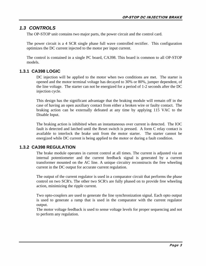
1.3 CONTROLS The OP-STOP unit contains two major parts, the power circuit and the control card.
The power circuit is a 4 SCR single phase full wave controlled rectifier. This configuration optimizes the DC current injected to the motor per input current.
The control is contained in a single PC board, CA398. This board is common to all OP-STOP models.
1.3.1 CA398 LOGIC DC injection will be applied to the motor when two conditions are met. The starter is opened and the motor terminal voltage has decayed to 30% or 80%, jumper dependent, of the line voltage. The starter can not be energized for a period of 1-2 seconds after the DC injection cycle.
This design has the significant advantage that the braking module will remain off in the case of having an open auxiliary contact from either a broken wire or faulty contact. The braking action can be externally defeated at any time by applying 115 VAC to the Disable Input.
The braking action is inhibited when an instantaneous over current is detected. The IOC fault is detected and latched until the Reset switch is pressed. A form C relay contact is available to interlock the brake unit from the motor starter. The starter cannot be energized while DC current is being applied to the motor or during a fault condition.
1.3.2 CA398 REGULATION The brake module operates in current control at all times. The current is adjusted via an internal potentiometer and the current feedback signal is generated by a current transformer mounted on the AC line. A unique circuitry reconstructs the free wheeling current in the DC output for accurate current regulation.
The output of the current regulator is used in a comparator circuit that performs the phase control on two SCR's. The other two SCR's are fully phased on to provide free wheeling action, minimizing the ripple current.
Two opto-couplers are used to generate the line synchronization signal. Each opto output is used to generate a ramp that is used in the comparator with the current regulator output. The motor voltage feedback is used to sense voltage levels for proper sequencing and not to perform any regulation.

OP-STOP DC INJECTION BRAKE
Page 4
2 SPECIFICATIONS
2.1 POWER RATING POWER 200-600VAC, 50/60 Hz CONTROL 115 VAC, 50 Hz or 120 VAC, 60 Hz RATING Intermittent duty, See Section 2.2 300% for 30 seconds, once every 30 minutes All models have 1600V PIV SCR's CONTACTS DC injection relay contacts rated at 1A, 120VAC PROTECTION Short circuit by HRC fuses or circuit breaker
(supplied upon request) Voltage surge protection by snubber's and MOV's across the SCR's
2.2 CURRENT AND FUSE RATING CURRENT RATING DCI
MODEL AMPS MOTOR
HP @ 575 V MOTOR
HP @ 460V FUSE AMPS
SCR TYPE
DCI-20 20.0 20.0 15.0 20.0 Module DCI-40 40.0 40.0 30.0 40.0 Module DCI-80 80.0 75.0 60.0 80.0 Module DCI-125 125.0 125.0 100.0 125.0 Module DCI-200 200.0 200.0 150.0 200.0 Disc DCI-300 300.0 300.0 250.0 300.0 Disc DCI-500 500.0 500.0 400.0 500.0 Disc
2.2.1 NOTES
2.2.1.1 The HP listing is for reference only. For proper selection use the current rating.
2.2.1.2 The fuses recommended are Class J time-delay type. This fuse is being suggested even though it may not protect the SCR in an output shorted condition while braking. It will protect the unit when starting to operate into a shorted output. In the case of a shorted SCR, the fuse is there to clear the fault only.
2.2.1.3 The RMS AC line current is equal to : AC RMS = DC Amps x √ Duty Cycle Assuming 10A motor, OP-STOP set at 300% current (30 A DC), free wheeling for 70% of the cycle, then the AC current is 16A.
2.2.1.4 All OP-STOP models are built without cooling fans because they are short duty rated.

OP-STOP DC INJECTION BRAKE
Page 5
2.3 SERVICE CONDITIONS ELEVATION For altitudes in excess of 2000 meters / 6600 feet above sea
level, all assemblies must be derated 1% for every 100 meters / 330 feet above
AMBIENT TEMPERATURE
Do not install in areas where ambient temperature falls below 0°C / 32°F or exceeds 40°C / 104°F
2.4 DIMENSIONS DCI
MODEL Height × Width × Depth
CHASSIS NEMA 1 / NEMA 12
DCI-20 43cm × 22cm × 15cm 33cm × 22cm × 18cm
16" × 8.5" × 6" 13" × 8.5" × 7"
DCI-40 43cm × 25cm × 19cm 33cm × 22cm × 18cm
17" × 10" × 8.5" 17" × 12" × 8.5"
DCI-80 43cm × 27cm × 21cm 43cm × 30cm × 27cm
17" × 10" × 8.5" 17" × 12" × 10.5"
DCI-125 53cm × 27cm × 23cm 53cm × 30cm × 27cm
21" × 10.5" × 9" 21" × 12" × 10.5"
DCI-200 28cm × 33cm × 27cm 61cm × 61cm × 30cm
11" × 13" × 10.5" 24" × 24" × 12"
DCI-300 42cm × 37cm × 28cm 76cm × 61cm × 30cm
16.5" × 14.5" × 11" 30" × 24" × 12"
DCI-500 45cm × 42cm × 36cm 76cm × 61cm × 30cm
17.5" × 16.5" × 14" 30" × 24" × 12"
NOTE: For dimensions of OP-STOP units in conjunction with SAF's OPAL solid state starter, refer to the OPAL manual reversing chassis dimensions.

OP-STOP DC INJECTION BRAKE
Page 6
2.5 SCR INSTALLATION SPECIFICATIONS 2.5.1.1 SCR TIGHTENING PROCEDURE
2.5.1.2 Clean both heat sink and SCR surfaces.
2.5.1.3 Apply a thin layer of joint compound (Noalox) to both SCR surfaces.
2.5.1.4 Observe correct SCR polarity.
2.5.1.5 Install SCR so that roll pins engage dimples on both sides of the SCR.
2.5.1.6 Tighten clamp bolts evenly until finger-tight.
2.5.1.7 Tighten each bolt according to table below (based on number of spring bars and size of bars).
* Note: SMALL clamps are 4.25 inches / 10.5 cm and LARGE clamps are 5 inches / 12.5 cm.
CLAMP SIZE SPRING BARS BOLT TURNS PAST FINGER TIGHT
SMALL 1 0.8
SMALL 2 1
LARGE 3 1.8
LARGE 4 1.8

OP-STOP DC INJECTION BRAKE
Page 7
3 CARD FUNCTIONS
3.1 CARD LAYOUT
1 2
CURRENT FBKCURRENT FBK
RESETRESETIOCIOC
PWRPWR
INJCTINJCT
L1L1 NINPUT 120VACINPUT 120VAC
1 2 3 4 5 6
MO
TOR
VFB
KM
OTO
R V
FBK
12
RZ24
RZ24
DC INJECTION BRAKE CARDDC INJECTION BRAKE CARD
CAUTION !!!CAUTION !!!MAINS VOLTAGE POTENTIALMAINS VOLTAGE POTENTIAL
SAFSAFK
1K
1G
1G
1K
2K
2G
2G
2K
3K
3G
3G
3K
4K
4G
4G
4
2
4
6
8
1010
1212
1414
1616
1818
2020
BRAKINGBRAKING TORQUETORQUE
HIHI LOLO
7
+24
V+
24V
CO
MC
OM
1A 2
50V
1A 2
50V
VOLTAGE LEVELVOLTAGE LEVEL
BURDENBURDEN
CA398-3CA398-3TIMETIME
DCDC
MO
TOR
VFB
K
INPUT 120VAC L1L1 N 1
TORQUE
DC INJECTION BRAKE CARD
1A 2
50V
1A 2
50V
1616
2020
1818
1414
1212
1010
8
6
4
2
IOCIOC RESETRESET
DCINJCT
PWRPWR
BURDENBURDEN
CO
MC
OM
+24
V+
24V
BRAKINGTIMETIME
K2
K2
31 2 4 65 7
MAINS VOLTAGE POTENTIAL
2
RZ24
RZ24
G4
G4
K4
K4
G3
G3
G2
G2
K3
K3
VOLTAGE LEVELVOLTAGE LEVELHIHI LOLO
CURRENT FBKCURRENT FBK
1 2
G1
G1
K1
K1
PRI PRI
SEC SEC
A
A
A
1 2 3
PRI PRI
SEC SEC
A
A
A
1 32
U11U11
OPTOPT
SCR1
SCR1
SCR2
SCR2
SCR3
SCR3
SCR4
SCR4
T2T2
T3T3
T4T4
T5T5
U7U7
U6U6
LD3LD3
LD1LD1
K1
K1
U12U12
U10U10
SW1
SW1
U2U2
J3J3
R7R7
RV2RV2
J2J2
LD2LD2
T1T1
U3U3
ISO1ISO1
ISO2ISO2
U5U5
RV1RV1
J5J5
FU1FU1
K2
K2
JP1JP1
J1J1
J4J4
U4U4
NE1NE1
U8U8
U9U9
ISO3ISO3
ISO4ISO4
J2J2
T1T1FU1FU1
ISO2ISO2
ISO1ISO1
OPTOPT
LD2LD2
LD3LD3
SW1
SW1
LD1
U3U3
U2U2
U6U6
U5U5
R7R7
J1J1
U4U4
RV1RV1 RV2RV2
T3T3
J4J4
K2
K2
U10U10
U8U8
U12U12
ISO4ISO4
K1
K1 ISO3ISO3
J5J5
T5T5
T4T4
SCR3
SCR3
NE1NE1
SCR4
SCR4
SCR2
SCR2
JP1JP1
U7U7 U9U9 U11U11
J3J3
T2T2
SCR1
SCR1
CA398 – DC INJECTION CARD
3.2 LED AND NEON INDICATIONS
LED NAME COLOUR DESCRIPTION
LD1 DC INJCT RED On when unit is braking
LD2 PWR GREEN Must be ON when 115VAC is applied
LD3 IOC RED Instantaneous Over-Current fault indication when illuminated
NE1 PHASE OK ORANGE Phase loss indication when neon not glowing

OP-STOP DC INJECTION BRAKE
Page 8
3.3 ADJUSTMENTS
3.3.1 POTENTIOMETERS POT NAME RANGE DEFAULT
SETTING DESCRIPTION
RV1 BRAKING TIME
1-60 sec 30% Adjust the braking time CW rotation increases the time
RV2 TORQUE 100-300% 50% Adjust DC current CW increases the braking torque (current)
3.3.2 1LINK SELECTION
LINK NAME POSITION DESCRIPTION
JP1 VOLTAGE LEVEL
LO (Normal)
Braking action starts when motor starter has opened and the motor terminal voltage has decreased to 30% of the line voltage.
HI Braking action starts when motor starter has opened and the motor terminal voltage has decreased to 80% of the line voltage. See important notes below.
HI setting is only used when the stopping time is critical and must be around 1-2 seconds. For this application 300% DC current is not adequate. Consult factory before using this jumper position. When the OP-STOP is set on the HI level a current surge could occur due to the motor CEMF and the free wheeling action of the power circuit.
3.3.3 PUSHBUTTON
PUSHBUTTON NAME DESCRIPTION
SW1 RESET Reset IOC fault trip

OP-STOP DC INJECTION BRAKE
Page 9
3.4 TERMINALS
3.4.1 CUSTOMER TERMINALS TERMINAL NO. DESCRIPTION J2 L1, N 115 VAC control voltage input, L1 being hot and N, neutral
L1 input is protected with internal fuse, 1A 250VAC J4 1, 2 115 VAC supply for external interlock contacts 3.0 A normally open contact from the motor starter auxiliary must
be connected between this teminal and terminals 1 or 2 to sense when the starter is de-energized to enable braking action When using a SAF OPAL starter in conjuction with the OP-STOP, this terminal is to be jumpered to terminal 1 or 2
4.0 When 115VAC from terminals 1 or 2 is applied to this input, braking is disabled Apply 115 VAC to this input to disable the brake
5.0 Common DCI relay contact The Form-C relay is de-energized while braking and when a fault exists
6.0 Normally open DCI relay auxiliary contact -7.0 Normally closed DCI relay auxiliary contact R7 1, 2 Burden resistor terminals for calibration of DC injection
current See table in Section 4.4
3.4.2 TERMINALS FOR INTERNAL USE TERMINAL NO. DESCRIPTION J1 24V, COM This terminal is used by SAF as a 24V input to provide
battery back up for DC injection in case of power loss
J3 1, 2 CURRENT FBK From current transformer for motor current feedback
J5 1, 2 MOTOR VFBK From T1, T2 motor terminals for motor voltage feedback
SCR1 G1, K1 Gate connection to SCR 1 SCR2 G2, K2 Gate connection to SCR 2 SCR3 G3, K3 Gate connection to SCR 3 SCR4 G4, K4 Gate connection to SCR 4 OPT 1-20 Provided for ribbon cable link to SAF's OPAL starter
This provides signals from the OPAL to the OP-STOP that indicate the run status of the starter, replacing the auxiliary input and prevents starting during DC injection or a fault
OP-STOP DC INJECTION BRAKE
Page 10
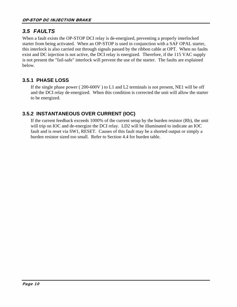
3.5 FAULTS When a fault exists the OP-STOP DCI relay is de-energized, preventing a properly interlocked starter from being activated. When an OP-STOP is used in conjunction with a SAF OPAL starter, this interlock is also carried out through signals passed by the ribbon cable at OPT. When no faults exist and DC injection is not active, the DCI relay is energized. Therefore, if the 115 VAC supply is not present the "fail-safe" interlock will prevent the use of the starter. The faults are explained below.
3.5.1 PHASE LOSS If the single phase power ( 200-600V ) to L1 and L2 terminals is not present, NE1 will be off and the DCI relay de-energized. When this condition is corrected the unit will allow the starter to be energized.
3.5.2 INSTANTANEOUS OVER CURRENT (IOC) If the current feedback exceeds 1000% of the current setup by the burden resistor (Rb), the unit will trip on IOC and de-energize the DCI relay. LD2 will be illuminated to indicate an IOC fault and is reset via SW1, RESET. Causes of this fault may be a shorted output or simply a burden resistor sized too small. Refer to Section 4.4 for burden table.

OP-STOP DC INJECTION BRAKE
Page 11
4 INSTALLATION AND START UP
4.1 INSPECTION The OP-STOP has been packaged to protect it from damage caused by normal handling during shipping; however mishandling may cause damage to the OP-STOP. Unpack the unit as soon as it is received and check for any shipping or storage damages. If damage is found, notify the carrier. Any damage claim must be filed by the customer since all shipments are F.O.B. SAF plant unless otherwise specified.
If the OP-STOP is not installed when received, store it in a clean, dry, well ventilated area, free from heat, humidity, oil, dust and metal particles.
4.2 SAFETY PRECAUTIONS CAUTION
Equipment is at line voltage when AC power is connected. Pressing "STOP" pushbutton does not remove AC mains potential. All phases must be
disconnected before it is safe to work on machinery or touch motor terminals or control equipment parts.
CAUTION Disconnect incoming voltage from unit before opening load side during DC
injection. Failure to observe this precaution can result in damage to disconnecting device and/or bodily injury.
The electrical code requires all equipment, starter motor, operator station, brake, etc... to be grounded properly. An incoming circuit breaker or disconnect switch must be locked open before wiring and servicing this electrical brake, motor, or other related equipment. This equipment must be installed and serviced only by qualified personnel, familiar with this unit. The user is responsible for ensuring that proper short circuit protection is provided by either a circuit breaker or HRC fuses.
4.3 MOUNTING GUIDELINES Standard Nema 1 OP-STOP units must be installed indoors in a well ventilated area, free from heat, humidity, oil, dust and metal particles.
One foot of clearance must be kept around the perimeter of the unit in a naturally cooled setup. The equipment must be mounted away from any heat source. See Section 2 for additional specifications and derating. Be aware that the heatsink may reach temperatures of 70°C / 158°F during normal operation. Do not install the unit in contact with any material that can not accept this temperature.
OP-STOP DC INJECTION BRAKE
Page 12
The OP-STOP must be mounted vertically and where it will not experience excessive shock or vibration.

OP-STOP DC INJECTION BRAKE
Page 13
4.4 WIRING GUIDELINES Follow all local electrical codes for installation requirements and wire sizing. Size the power wiring as per local code and on long wire runs it is recommended to use a larger wire size. Power factor correcting capacitors MUST NOT be connected to the OP-STOP output. If desired, they must be connected on the line side of the unit. Capacitors can be connected before starting or preferably after the motor has reached full speed.
4.5 START UP
4.5.1 CHECKS BEFORE POWER-UP
4.5.1.1 Ensure that all electrical connections are completed as shown on schematics in section 6, and that connections are properly tightened. The most important connection is the interlock between the OP-STOP and the starter.
4.5.1.2 Ensure that the burden resistor is equal or larger than the value listed in the table below or calculated by the following equation:
Rb = Effective Current Transformer Ratio ÷ Motor Nameplate Amps
4.5.1.3 Set JP1 link to LO.
4.5.1.4 Adjust RV2, braking torque, and RV1, braking time to 50%
4.5.1.5 Install a Disable switch between terminals 2 and 4 of J3 in the open position. Switch is to be closed once the motor has reached zero speed or if any problems occur during braking.
4.5.1.6 If a Disable switch is not used, then set RV2 to 30%, about 20 seconds or lower.
WARNING!
DO NOT OPEN LOAD SIDE DISCONNECT DEVICE DURING DC
INJECTION CYCLE. FAILURE TO OBSERVE THIS WARNING WILL RESULT IN DAMAGE TO THE DISCONNECTING DEVICE AND MAY
CAUSE PERSONAL INJURY.

OP-STOP DC INJECTION BRAKE
Page 14
MODEL
MOTOR
AMPS BURDEN
RESISTOR (¼ W) EFFECTIVE CT
RATIO SS6-15 with DCI 10.0 68 Ω 750 : 1 15.0 47 Ω DCI-20 or
SS6-30 with DCI 20.0 39 Ω 750 : 1
30.0 27 Ω DCI-40 or
SS6-50 with DCI 40.0 39 Ω 1500 : 1
50.0 33 Ω DCI-80 or
SS6-80 with DCI 60.0 39 Ω 2500 : 1
80.0 33 Ω DCI-125 or
SS6-125 with DCI 100.0 27 Ω 2500 : 1
125.0 22 Ω DCI-200 or
SS6-200 with DCI 150.0 18 Ω 2500 : 1
200.0 12 Ω DCI-300 or
SS6-360 with DCI 200.0 27Ω 5000 : 1
300.0 18 Ω DCI-500 or
SS6-500 with DCI 400.0 22 Ω 8500 : 1
500.0 18 Ω
4.5.2 WITH POWER ON 4.5.2.1 Run the motor up to full speed and command the starter off. If the motor reaches zero
speed from the DC injection cycle, close the switch to the Disable Input to disable the braking.
4.5.2.2 Re-adjust the braking torque pot, RV2, if the actual braking time has to be increased or decreased to bring the motor to zero speed.
4.5.2.3 Once the braking torque is set, then adjust RV1 to match the DC injection time with the actual stopping time of the motor. Typically, the injection should decease when the motor is at zero speed or shortly after. LD1, DC INJCT is an indication of braking. Each 10% graduation in RV1 corresponds to approximately 6 seconds.
WARNING! ALLOW TIME FOR THE MOTOR TO COOL BEFORE ANOTHER
START / STOP SEQUENCE IS INITIATED FREQUENT START / STOP COULD CAUSE MOTOR DAMAGE
DUE TO OVERHEATING

OP-STOP DC INJECTION BRAKE
Page 15
5 TYPICAL CONNECTIONS
5.1 STAND ALONE DC INJECTION UNIT WITH ZERO SPEED DISABLE

OP-STOP DC INJECTION BRAKE
Page 16
5.2 OPAL STARTER WITH DC INJECTION
SCR1
SCR2
SCR4
SCR3
SCR5
SCR6
CT3
L1 L2 L3
CT2
CT1
MO
V
MO
V
MO
V
T1 T2 T3
200-
600V
3 PH
ASE
50/6
0HZ
PRO
TEC
TED
120V
, 60H
z/11
0V ,5
0Hz
SUPP
LY
K6
TO S
CR
GAT
ES
G1
K1
G2
K2
G3
K3
G4
K4
G5
K5
G6
43
21
CA
392-
2
FAU
LTRU
N
12
34
56
7TB
AC
1
NRU
N
FAU
LT
RAT
E
STEP
STA
RT
STO
P
MO
TOR
IND
UC
TIO
N3
PHA
SE
TIM
E
CA
398-
3
NL1
K4
G1
K1
G2
K2
G3
K3
G4
J21
23
45
6J4
12
J3
MX
DIS
AB
LE
DC
INJE
CTI
ON
+V
IOC
BU
RDEN
RESI
STO
R
CU
RREN
TFB
K
TORQ
UE
CT4
1 2
VFB
SCR1
SCR8
SCR4
SCR9
PRO
TEC
TED
OPT
MO
V
SCR8
MO
V
SCR9
7
1 2
DC
I
J5
R7
BRA
KIN
G
BRA
KIN
G
OPT

OP-STOP DC INJECTION BRAKE
Page 17
5.3 REVERSING OPAL STARTER WITH DC INJECTION, 125 AMPS AND BELOW
SCR1
SCR2
SCR4
SCR3
SCR5
SCR6
CT3
L1 L2 L3
CT2
CT1
MO
V
MO
V
MO
V
T1 T2 T3
200-
600V
3 PH
ASE
50/6
0HZ
PRO
TEC
TED
120V
, 60H
z/11
0V ,5
0Hz
SUPP
LY
K6
TO S
CR
GAT
ES
G1
K1
G2
K2
G3
K3
G4
K4
G5
K5
G6
43
21
CA
392-
2
FAU
LTRU
N
12
34
56
7TB
AC
1
NRU
N
FAU
LT
RAT
E
STEP
STA
RT
STO
P
MO
TOR
IND
UC
TIO
N3
PHA
SE
TIM
E
CA
398-
3
NL1
K4
G1
K1
G2
K2
G3
K3
G4
J21
23
45
6J4
12
J3
MX
DIS
AB
LE
DC
INJE
CTI
ON
+V
IOC
BU
RDEN
RESI
STO
R
CU
RREN
TFB
K
TOR
QU
E
CT4
1 2
VFB
SCR1
SCR8
SCR4
SCR9
PRO
TEC
TED
OPT
NEU
T.
TIM
E D
ELAY
REV
ERSI
NG
CA
388-
4
AC
FWD
/REV
43
21
P1
OPT
120V
TO S
CR
GAT
ES
K10
G7
K7
G8
K8
G9
K9
G10
FWD
REV
FWD
/REV
SWIT
CH
P1
MO
V
SCR8
SCR7
MO
V
SCR9
SCR1
0
7
1 2
DC
I
J5
R7
BRA
KIN
G
BRA
KIN
G
OPT

OP-STOP DC INJECTION BRAKE
Page 18
5.4 REVERSING OPAL STARTER WITH DC INJECTION, 200 AMPS AND ABOVE
SCR1
SCR2
SCR4
SCR3
SCR5
SCR6
CT3
L1 L2 L3
CT2
CT1
MO
V
MO
V
MO
V
T1 T2 T3
200-
600V
3 PH
ASE
50/6
0HZ
PRO
TEC
TED
120V
, 60H
z/11
0V ,5
0Hz
SUPP
LY
K6
TO S
CR
GAT
ES
G1
K1
G2
K2
G3
K3
G4
K4
G5
K5
G6
43
21
CA
392-
2
FAU
LTRU
N
12
34
56
7TB
AC
1
NRU
N
FAU
LT
RATE
STEP
STA
RT
STO
P
MO
TOR
IND
UC
TIO
N3
PHA
SE
TIM
E
CA
398-
3
NL1
K4
G1
K1
G2
K2
G3
K3
G4
J21
23
45
6J4
12
J3
MX
DIS
AB
LE
DC
INJE
CTI
ON
+V
IOC
BU
RDEN
RESI
STO
R
CU
RREN
TFB
K
TORQ
UE
CT4
1 2
VFB
SCR1
SCR8
SCR4
SCR9
PRO
TEC
TED
OPT
NEU
T.
TIM
E D
ELAY
REV
ERSI
NG
CA
388-
4
AC
FWD
/REV
43
21
P1
OPT
120V
TO S
CR
GAT
ES
K10
G7
K7
G8
K8
G9
K9
G10
FWD
REV
FWD
/REV
SWIT
CH
P1
MO
V
SCR8
SCR7
MO
V
SCR9
SCR1
0
7
1 2
DC
I
J5
R7
BRA
KIN
G
BRA
KIN
G
OPT

OP-STOP DC INJECTION BRAKE
Page 19
6 SPARE PARTS
OP-STOP MODEL
CT RATIO
CT PART NO.
SCR PART NO.
SNUBBER CARD
CONTROL CARD DESCRIPTION
DCI-20 1500:1 T261123 N10SP03 CA524 CA398
DCI-40 1500:1 T261123 N10SP06 CA524 CA398
DCI-80 2500:1 T262230 N10SP16 CA524 CA398
DCI-125 2500:1 T262230 N20SP06 CA524 CA398
DCI-200 2500:1 T262230 N728452 CA232 CA398
DCI-300 5000:1 T265320 N718602 CA232 CA398
DCI-500 8500:1 T268320 N718133 CA232 CA398

www.safdrives.com
email: [email protected](Replies given within 24 hours)
18 Neville Street, Unit CNew Hamburg, ON N3A 4G7
Tel: 519-662-6489Fax: 1-866-280-5247
www.opalstarters.com
Installation & Operating Procedures
Opal OP-STOP Series
DC INJECTION BRAKEFOR 3 PHASE INDUCTION MOTORS