Installation, Operating and Service Instructions for FORCE ...
44
109444-03 - 12/19 9700609 FORCE • Water Boiler • Cast Iron • Chimney Vent • Gas Fired TO THE INSTALLER: Affix these instructions adjacent to boiler. Provide model number and serial number when seeking information and support. TO THE CONSUMER: Retain these instructions for future reference. Contact heating contractor for all issues and support. Models: • FORCE02E • FORCE03E • FORCE04E • FORCE05E • FORCE06E • FORCE07E • FORCE08E • FORCE09E Manual Contents Page Specifications 3 Pre-installation 4 Removing Existing Boiler 5 Clearances 5 Venting 7 Water Piping 10 Gas Piping 13 Electrical 14 System Start-Up and Checkout 17 Operation 22 Before Leaving Jobsite 24 Service and Maintenance 25 How It Works 29 Troubleshooting 31 Service Parts 33 Appendix 40 WARNING Improper installation, adjustment, alteration, service or maintenance can cause property damage, injury, or loss of life. For assistance or additional information, consult a qualified installer, service agency or gas supplier. Read these instructions carefully before installing. ! Installation, Operating and Service Instructions for TM
Transcript of Installation, Operating and Service Instructions for FORCE ...

109444-03 - 12/19
9700609
FORCE • Water Boiler• Cast Iron• Chimney Vent• Gas Fired
TO THE INSTALLER: Affix these instructions adjacent to boiler.Provide model number and serial number when seeking information and support.
TO THE CONSUMER: Retain these instructions for future reference.Contact heating contractor for all issues and support.
Models:
• FORCE02E• FORCE03E• FORCE04E• FORCE05E• FORCE06E• FORCE07E• FORCE08E• FORCE09E
Manual Contents Page
Specifications . . . . . . . . . . . . . . . . . . . . . . . . . . 3Pre-installation . . . . . . . . . . . . . . . . . . . . . . . . . . 4Removing Existing Boiler . . . . . . . . . . . . . . . . . 5Clearances . . . . . . . . . . . . . . . . . . . . . . . . . . . . . 5Venting . . . . . . . . . . . . . . . . . . . . . . . . . . . . . . . . 7Water Piping . . . . . . . . . . . . . . . . . . . . . . . . . . . 10Gas Piping . . . . . . . . . . . . . . . . . . . . . . . . . . . . 13Electrical . . . . . . . . . . . . . . . . . . . . . . . . . . . . . . 14System Start-Up and Checkout . . . . . . . . . . . 17Operation . . . . . . . . . . . . . . . . . . . . . . . . . . . . . 22Before Leaving Jobsite . . . . . . . . . . . . . . . . . . 24Service and Maintenance . . . . . . . . . . . . . . . . 25How It Works . . . . . . . . . . . . . . . . . . . . . . . . . . 29Troubleshooting . . . . . . . . . . . . . . . . . . . . . . . . 31Service Parts . . . . . . . . . . . . . . . . . . . . . . . . . . 33Appendix . . . . . . . . . . . . . . . . . . . . . . . . . . . . . 40
WARNING
Improper installation, adjustment, alteration, service or maintenance can cause property damage, injury, or loss of life. For assistance or additional information, consult a qualified installer, service agency or gas supplier. Read these instructions carefully before installing.
!
Installation, Operating and Service Instructions for
TM
2
FORCE E Installation, Operating & Service Manual
109444-03 - 12/19
The following terms are used throughout this manual to bring attention to the presence of hazards of various risk levels, or to important information concerning product life .
The City of New York requires a Licensed Master Plumber supervise the installation of this product.
The Massachusetts Board of Plumbers and Gas Fitters has listed the FORCE E Boiler. See the Massachusetts Board of Plumbers and Gas Fitters website, http://licensing .reg .state .ma .us/pubLic/pl_products/pb_product .asp for the latest Approval Code or ask your local Sales Representative.The Commonwealth of Massachusetts requires this product to be installed by a licensed Plumber or Gas fitter.
NOTICE: Indicates special instructions on installation, operation, or service which are important but not related to personal injury hazards.
DANGER
Indicates a hazardous situation that, if not avoided, will result in death or serious injury.
CAUTION
Indicates a hazardous situation that, if not avoided, could result in minor or moderate injury.
WARNING
Indicates a hazardous situation that, if not avoided, could result in death or serious injury.
DANGER
Explosion Hazard . DO NOT store or use gasoline or other flammable vapors or liquids in the vicinity of this or any other appliance.
If you smell gas vapors, DO NOT try to operate any appliance - DO NOT touch any electrical switch or use any phone in the building. Immediately, call the gas supplier from a remotely located phone. Follow the gas supplier’s instructions or if the supplier is unavailable, contact the fire department.
WARNING
This boiler must only be serviced and repaired by skilled and experienced service technicians .
• If any controls are replaced, they must be replaced with identical models. • Read, understand and follow all the instructions and warnings contained in all the sections of this manual. • If any electrical wires are disconnected during service, clearly label the wires and assure that the wires are reconnected properly. • Never jump out or bypass any safety or operating control or component of this boiler. • Assure that all safety and operating controls and components are operating properly before placing the boiler back in service. • Annually inspect all vent gaskets and replace any exhibiting damage or deterioration.
! !
!
!
!
3
FORCE E Installation, Operating & Service Manual
109444-03 - 12/19
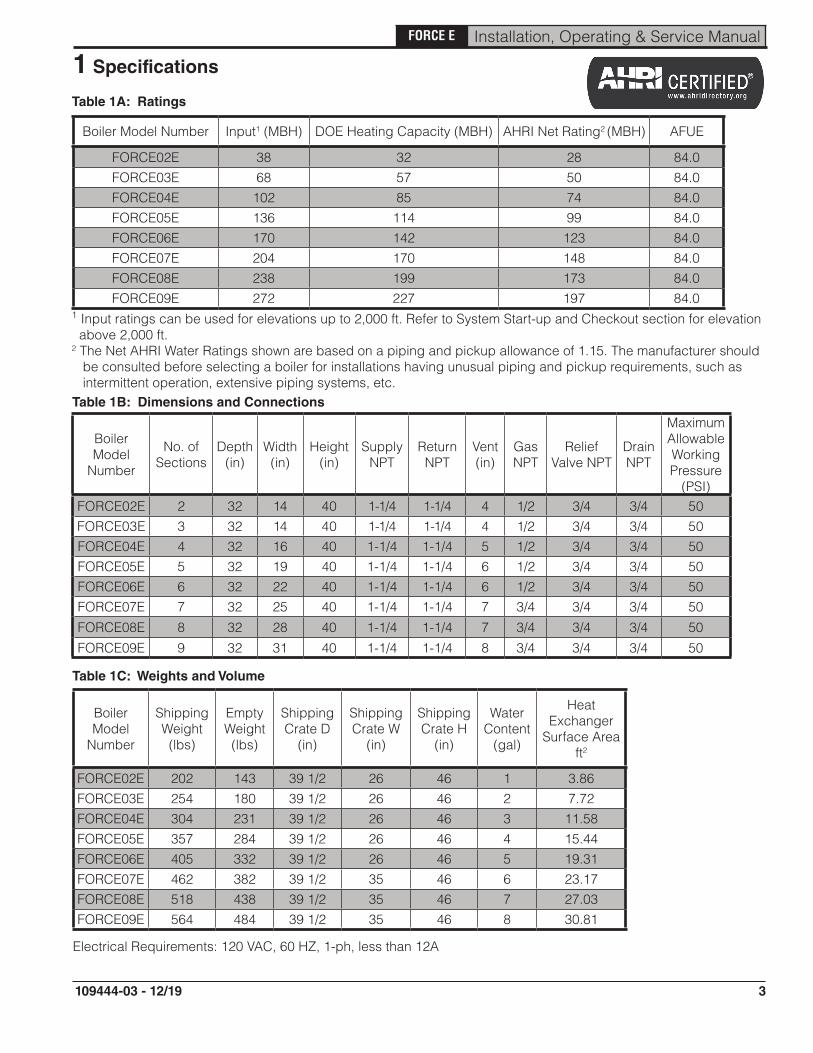
Table 1A: Ratings
Boiler Model Number Input1 (MBH) DOE Heating Capacity (MBH) AHRI Net Rating2 (MBH) AFUE
FORCE02E 38 32 28 84.0FORCE03E 68 57 50 84.0FORCE04E 102 85 74 84.0FORCE05E 136 114 99 84.0FORCE06E 170 142 123 84.0FORCE07E 204 170 148 84.0FORCE08E 238 199 173 84.0FORCE09E 272 227 197 84.0
1 Input ratings can be used for elevations up to 2,000 ft. Refer to System Start-up and Checkout section for elevation above 2,000 ft.2 The Net AHRI Water Ratings shown are based on a piping and pickup allowance of 1.15. The manufacturer should be consulted before selecting a boiler for installations having unusual piping and pickup requirements, such as intermittent operation, extensive piping systems, etc.Table 1B: Dimensions and Connections
Boiler Model
Number
No. of Sections
Depth (in)
Width (in)
Height (in)
Supply NPT
Return NPT
Vent (in)
Gas NPT
Relief Valve NPT
Drain NPT
Maximum Allowable Working Pressure
(PSI)FORCE02E 2 32 14 40 1-1/4 1-1/4 4 1/2 3/4 3/4 50FORCE03E 3 32 14 40 1-1/4 1-1/4 4 1/2 3/4 3/4 50FORCE04E 4 32 16 40 1-1/4 1-1/4 5 1/2 3/4 3/4 50FORCE05E 5 32 19 40 1-1/4 1-1/4 6 1/2 3/4 3/4 50FORCE06E 6 32 22 40 1-1/4 1-1/4 6 1/2 3/4 3/4 50FORCE07E 7 32 25 40 1-1/4 1-1/4 7 3/4 3/4 3/4 50
FORCE08E 8 32 28 40 1-1/4 1-1/4 7 3/4 3/4 3/4 50
FORCE09E 9 32 31 40 1-1/4 1-1/4 8 3/4 3/4 3/4 50
Boiler Model
Number
Shipping Weight (lbs)
Empty Weight (lbs)
Shipping Crate D
(in)
Shipping Crate W
(in)
Shipping Crate H
(in)
Water Content
(gal)
Heat Exchanger
Surface Area ft2
FORCE02E 202 143 39 1/2 26 46 1 3.86FORCE03E 254 180 39 1/2 26 46 2 7.72FORCE04E 304 231 39 1/2 26 46 3 11.58FORCE05E 357 284 39 1/2 26 46 4 15.44FORCE06E 405 332 39 1/2 26 46 5 19.31FORCE07E 462 382 39 1/2 35 46 6 23.17FORCE08E 518 438 39 1/2 35 46 7 27.03FORCE09E 564 484 39 1/2 35 46 8 30.81
Table 1C: Weights and Volume
1 Specifications
Electrical Requirements: 120 VAC, 60 HZ, 1-ph, less than 12A

4
FORCE E Installation, Operating & Service Manual
109444-03 - 12/19
2 Pre-installation
WARNING
Carefully read all instructions before installing boiler. Failure to follow all instructions in proper order can cause personal injury or death.
A. FORCE E boiler is Category I, draft hood equipped appliance with vent damper.
B. Installation must conform to requirements of authority having jurisdiction. In absence of such requirements, installation must conform to National Fuel Gas Code, ANSI Z223.1/NFPA 54.
C. Appliance is design listed for installation on combustible flooring and must not be installed on carpeting.
D. Provide clearance between boiler jacket and combustible material in accordance with authority having jurisdiction. Minimum clearances outlined in Figures 4-1 and 4-2.
E. Provide practical service clearances. Minimum 24" from left side and front jacket panels is recommended for servicing.
F. Install on level floor. For basement installation provide concrete base if floor is not level or if water may be encountered on floor around boiler.
G. Protect gas ignition system components from water (dripping, spraying, rain, etc.) during boiler operation and service (circulator replacement, condensate trap, control replacement, etc.).
H. Provide combustion and ventilation air in accordance with the section "Air for Combustion and Ventilation," of the National Fuel Gas Code, ANSI Z223.1/NFPA 54, or applicable provisions of local building codes.
WARNING
Adequate combustion and ventilation air must be provided to assure proper combustion and dilution air.
I. Do not install boiler where gasoline or other flammable vapors or liquids are stored. Avoid areas near chemical products containing chlorine, chloride based salts, chloro/fluorocarbons, paint removers, cleaning solvent, and detergents.
J. Consider using boiler bypass described in Section 6 "Water Piping" for systems which have a large volume or excessive radiation where low boiler water temperatures may be encountered.
K. Where required by authority having jurisdiction, installation must conform to standard for Controls and Safety Devices for Automatically Fired Boilers, ANSI/ASME CSD-1.
L. A hot water boiler installed above radiation level or as required by the authority having jurisdiction must be provided with a low water cutoff device. The Hydrostat 3200 LWCO is supplied with boiler.
!
!
Components Shipped with Boiler: Vent damper Circulator Miscellaneous parts bag (Supply water manifold, Temperature/pressure gauge, 30 psi safety relief valve, drain valve, circulator flanges)
IMPORTANT
This boiler is equipped with a feature that saves energy by reducing the boiler water temperature as the heating load decreases. This feature is equipped with an override which is provided primarily to permit the use of an external energy management system that serves the same function. THIS OVERRIDE MUST NOT BE USED UNLESS AT LEAST ONE OF THE FOLLOWING CONDITIONS IS TRUE: • An external energy management system is installed that reduces the boiler water temperature as the heating load decreases. • This boiler is not used for any space heating. • This boiler is part of a modular or multiple boiler system having a total input of 300,000 BTU/hr or greater. • This boiler is equipped with a tankless coil.

5
FORCE E Installation, Operating & Service Manual
109444-03 - 12/19
3 Removing Existing Boiler
A. If an Existing Boiler is Removed:
When an existing boiler is removed from a common venting system, the common venting system is likely to be too large for proper venting of the appliances remaining connected to it.
At the time of removal of an existing boiler, the following steps shall be followed with each appliance remaining connected to the common venting system placed in operation, while the other appliances remaining connected to the common venting system are not in operation:
1. Seal any unused openings in the common venting system.
2. Visually inspect the venting system for proper size and horizontal pitch and determine there is no blockage or restriction, leakage, corrosion, and other deficiencies which could cause an unsafe condition.
3. Insofar as is practical, close all building doors and windows and all doors between the space in which the appliances remaining connected to the common venting system are located and other spaces of the building. Turn on clothes dryers and any appliance not connected to the common venting system. Turn on any exhaust fans, such as range hoods and bathroom exhausts, so they will operate at maxi mum speed. Do not operate a summer exhaust fan. Close fireplace dampers.
4. Place in operation the appliance being inspected. Follow the Lighting (or Operating) Instructions. Adjust thermo stat so appliance will operate continuously.
5. Test for spillage at the draft hood relief opening after 5 minutes of main burner operation. Use the flame of a match or candle, or smoke from a cigarette, cigar or pipe.
6. After it has been determined that each appliance remain ing connected to the common venting system properly vents when tested as outlined above, return doors, win dows, exhaust fans, fireplace dampers and any other gas-burning appliance to their previous condition of use.
7. Any improper operation of the common venting system should be corrected so the installation conforms with the National Fuel Gas Code, ANSI Z223.1/NFPA 54. When resizing any portion of the common venting system, the common venting system should be resized to approach the minimum size as determined using the appropriate tables in Chapter 13 of the National Fuel Gas Code, ANSI Z223.1/NFPA 54.
4 Clearances
A. All Installations
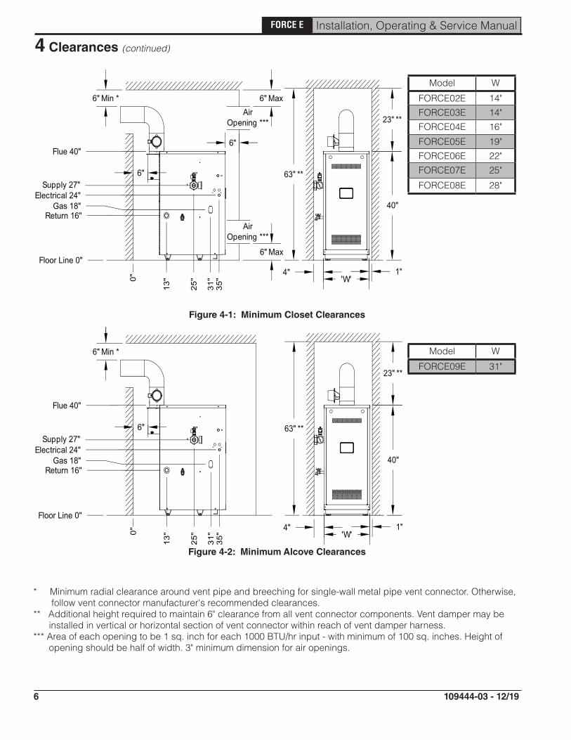
1. Minimum clearances to combustible materials are shown in Figures 4-1 and 4-2. Recommended for servicing: 24" minimum for left side and front jacket panels .
2. Closet Installation - Models FORCE02E, FORCE03E, FORCE04E, FORCE05E, FORCE06E,FORCE07E, & FORCE08E are listed for closet installation. See Figure 4-1.
3. Alcove Installation (no front door)- Model FORCE09E is listed for alcove installation. See Figure 4-2.
4. Hot water pipes: at least 1/2" from combustible material.
B. Provide Combustion and Ventilation Air in accordance with the section "Air for Combustion and Ventilation", of the National Fuel Gas Code, ANSI Z223.1/NFPA, or applicable provisions of local building codes.
6
FORCE E Installation, Operating & Service Manual
109444-03 - 12/19
4 Clearances (continued)
Figure 4-1: Minimum Closet Clearances
Model W
FORCE02E 14"FORCE03E 14"FORCE04E 16"
FORCE05E 19"FORCE06E 22"FORCE07E 25"
FORCE08E 28"
* Minimum radial clearance around vent pipe and breeching for single-wall metal pipe vent connector. Otherwise, follow vent connector manufacturer's recommended clearances.** Additional height required to maintain 6" clearance from all vent connector components. Vent damper may be installed in vertical or horizontal section of vent connector within reach of vent damper harness.*** Area of each opening to be 1 sq. inch for each 1000 BTU/hr input - with minimum of 100 sq. inches. Height of opening should be half of width. 3" minimum dimension for air openings.
Model W
FORCE09E 31"
Figure 4-2: Minimum Alcove Clearances

7
FORCE E Installation, Operating & Service Manual
109444-03 - 12/19
5 Venting
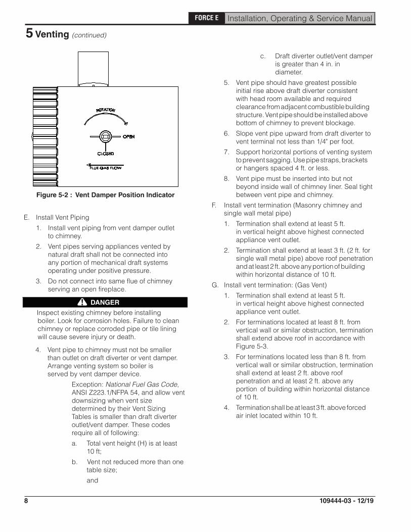
C. Install Vent Damper
OPEN THE VENT DAMPER CARTON and remove Installation Instructions. READ INSTALLATION INSTRUCTIONS THOROUGHLY before proceeding.
Automatic gas control valve supplied on each FORCE E boiler provides redundancy referenced in vent damper Installation Instructions.
Figure 5-1 : Vent Damper Installation
A. Inspect chimney and remove any obstructions or restric tions. Clean chimney if previously used for solid or liquid fuel-burning appliances or fireplaces.
B. Locate blocked vent switch on boiler draft hood. Verify connections are made.
CAUTION
Do not use one vent damper to control more than one heating appliance.
!
1. Vent damper must be same size as outlet of vent supplied with boiler (see Table 1B). Unpack damper carefully - DO NOT FORCE IT CLOSED! Forcing damper may damage motor and void warranty.
Insert pilot vent plug into gate and fold over tabs.
1. Type B or Type L gas vent. Install in accordance with manufacturer's installation instructions.
2. Masonry or metal chimney. Build and install in accordance with local building codes; or local authority having jurisdiction; or Standard for Chimneys, Fireplaces, Vents, and Solid Fuel Burning Appliances, NFPA 211.
Masonry chimney must be lined with listed clay flue lining or listed chimney lining system.
3. Single wall metal vent. Allowed by ANSI Z223.1/NFPA 54 under very restrictive conditions.
4. Do not use CPVC, PVC, Polypropylene or any other non-metallic vent pipe. Do not use cellular core PVC (ASTM F891), cellular core CPVC, or Radel® (polyphenolsulfone).
5. Do not cover non-metallic vent pipe and fittings with thermal insulation.
2. Mount the vent damper assembly onto draft hood. (Refer to Figure 5-1 and to instructions packed with vent damper for specific instructions). Do not modify either draft hood or vent damper.
NOTICE: Provide adequate clearance for servicing.
3. Locate vent damper position indicating means to be visible following installation.
4. Plug factory harness vent damper connector into damper motor polarized receptacle.
WARNING
Do not alter draft hood or place any obstruction or non listed damper in breeching or vent system. Flue gas spillage and carbon monoxide production can occur.
!
D. Install vent system in accordance with "Venting of Appliances" of the National Fuel Gas Code, ANSI Z223.1/NFPA 54, or applicable provisions of local building codes. The FORCE E boiler is a Category I, draft hood equipped appliance with vent damper.
8
FORCE E Installation, Operating & Service Manual
109444-03 - 12/19
5 Venting (continued)
E. Install Vent Piping
1. Install vent piping from vent damper outlet to chimney.
2. Vent pipes serving appliances vented by natural draft shall not be connected into any portion of mechanical draft systems operating under positive pressure.
3. Do not connect into same flue of chimney serving an open fireplace.
4. Vent pipe to chimney must not be smaller than outlet on draft diverter or vent damper. Arrange venting system so boiler is served by vent damper device.
Exception: National Fuel Gas Code, ANSI Z223.1/NFPA 54, and allow vent downsizing when vent size determined by their Vent Sizing Tables is smaller than draft diverter outlet/vent damper. These codes require all of following:
a. Total vent height (H) is at least 10 ft;
b. Vent not reduced more than one table size;
and
DANGER
Inspect existing chimney before installing boiler. Look for corrosion holes. Failure to clean chimney or replace corroded pipe or tile lining will cause severe injury or death.
!
Figure 5-2 : Vent Damper Position Indicator
c. Draft diverter outlet/vent damper is greater than 4 in. in diameter.
5. Vent pipe should have greatest possible initial rise above draft diverter consistent with head room available and required clearance from adjacent combustible building structure. Vent pipe should be installed above bottom of chimney to prevent blockage.
6. Slope vent pipe upward from draft diverter to vent terminal not less than 1/4" per foot.
7. Support horizontal portions of venting system to prevent sagging. Use pipe straps, brackets or hangers spaced 4 ft. or less.
8. Vent pipe must be inserted into but not beyond inside wall of chimney liner. Seal tight between vent pipe and chimney.
F. Install vent termination (Masonry chimney and single wall metal pipe)
1. Termination shall extend at least 5 ft. in vertical height above highest connected appliance vent outlet.
2. Termination shall extend at least 3 ft. (2 ft. for single wall metal pipe) above roof penetration and at least 2 ft. above any portion of building within horizontal distance of 10 ft.
G. Install vent termination: (Gas Vent)
1. Termination shall extend at least 5 ft. in vertical height above highest connected appliance vent outlet.
2. For terminations located at least 8 ft. from vertical wall or similar obstruction, termination shall extend above roof in accordance with Figure 5-3.
3. For terminations located less than 8 ft. from vertical wall or similar obstruction, termination shall extend at least 2 ft. above roof penetration and at least 2 ft. above any portion of building within horizontal distance of 10 ft.
4. Termination shall be at least 3 ft. above forced air inlet located within 10 ft.

9
FORCE E Installation, Operating & Service Manual
109444-03 - 12/19
5 Venting (continued)
Figure 5-3 : Termination Location for Gas Vent
Roof Slope Heights
Roof Slope ft.Flat to 6/12 1.0
Over 6/12 to 7/12 1.25Over 7/12 to 8/12 1.5Over 8/12 to 9/12 2.0Over 9/12 to 10/12 2.5Over 10/12 to 11/12 3.25Over 11/12 to 12/12 4.0Over 12/12 to 14/12 5.0Over 14/12 to 16/12 6.0Over 16/12 to 18/12 7.0Over 18/12 t 20/12 7.5Over 20/12 to 21/12 8.0

10
FORCE E Installation, Operating & Service Manual
109444-03 - 12/19
WARNING
Failure to properly pipe boiler may result in improper operation and damage to boiler or building.
A. Design and install boiler and system piping to prevent oxygen contamination of boiler water.
Oxygen contamination sources are system leaks requiring addition of makeup water, fittings, and oxygen permeable materials in distribution system. Eliminate oxygen contamination by repairing system leaks, repairing fittings, and using non-permeable materials in distribution system.
B. Install circulator with flanges, gaskets and bolts provided.
Figure 6-1: Standard Near Boiler Piping
!
6 Water Piping
WARNING
Safety relief valve discharge piping must be piped near floor to eliminate potential of severe burns. Do not pipe in any shut-off valves between:
1. Safety relief valve and boiler
2. Safety relief valve and discharge
Union may be installed in safety relief valve piping.
!
C. Install safety relief valve. See Figure 6-1 and 6-2. Safety relief valve must be installed with spindle in vertical position.
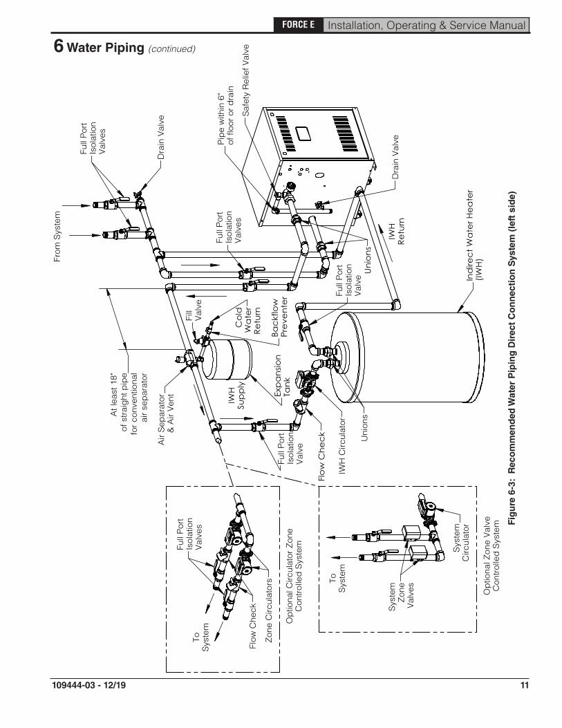
D. Connect system supply and return piping to boiler. Refer to Figures 6-3 and 6-4. Also consult Residential Hydronic Heating Installation and Design I=B=R Guide. Maintain minimum ½ inch clearance from hot water piping to combustible materials.
E. If necessary, supply and return may be connected to right side of boiler by removing 1-1/4" plugs from right side of block (under knockouts in jacket).
NOTICE: Both supply and return connections must be made on same side of boiler.
F. If boiler is used in connection with refrigeration system, See Appendix: "Combination Refrigeration/Heating System".
G. Use a system bypass if boiler is to be operated in a system which has a large volume or excessive radiation where low boiler water temperatures may be encountered (i.e. converted gravity circulation system, etc.). (See Appendix "Low Return Water Temperatures").
H. Perform a long term pressure test of hydronic system, isolate boiler to avoid a pressure loss due to escape of air trapped in boiler.
To perform a long term pressure test including the boiler, ALL trapped air must first be removed from the boiler.
A loss of pressure during such a test, with no visible water leakage, is an indication that the boiler contained trapped air.
SafetyReliefValve
Right Side
Drain
Return
Temperature& Pressure
Gauge
Figure 6-2: Alternate Near Boiler Piping
11
FORCE E Installation, Operating & Service Manual
109444-03 - 12/19
Fig
ure
6-3
: R
eco
mm
end
ed W
ater
Pip
ing
Dir
ect
Co
nn
ecti
on
Sys
tem
(le
ft s
ide)
6 Water Piping (continued)
At l
east
18"
of s
trai
ght
pip
efo
r co
nven
tiona
lai
r se
par
ator
ToS
yste
m
ToS
yste
m
Op
tiona
l Circ
ulat
or Z
one
Con
trol
led
Sys
tem
Op
tiona
l Zon
e V
alve
Con
trol
led
Sys
tem
Sys
tem
Circ
ulat
or
Sys
tem
Zon
eV
alve
s
Zon
e C
ircul
ator
s
Full
Por
tIs
olat
ion
Val
ves
Flow
Che
ck
From
Sys
tem
Full
Por
tIs
olat
ion
Val
ves
Dra
in V
alve
Saf
ety
Rel
ief V
alve
Pip
e w
ithin
6"
of fl
oor
or d
rain
Dra
in V
alve
IWH
Retu
rn
IWH
Sup
ply
Ind
irec
t Wa
ter H
ea
ter
(IWH
)
Air
Sep
arat
or&
Air
Ven
t Exp
ans
ion
Tank
Bac
kflo
wPr
eve
nte
r
Fill
Val
ve
Co
ldW
ate
rRe
turn
Full
Por
tIs
olat
ion
Val
ves
Uni
ons
Flo
w C
hec
k
IWH
Circ
ulat
or
Full
Por
tIs
olat
ion
Val
ve
Uni
ons
Full
Por
tIs
olat
ion
Val
ve

12
FORCE E Installation, Operating & Service Manual
109444-03 - 12/19
6 Water Piping (continued)
'C'
'B'
'A'
ToSy
stem
ToSy
stem
Opt
iona
l Circ
ulat
or Z
one
Con
trolle
d Sy
stem
Opt
iona
l Zon
e Va
lve
Con
trolle
d Sy
stem
Syst
emC
ircul
ator
Syst
emZo
neVa
lves
Zone
Circ
ulat
ors
Full
Port
Isol
atio
nVa
lves
Flow
Che
ck
From
Sys
tem
Full
Port
Isol
atio
nVa
lves
Dra
in V
alve Sa
fety
Rel
ief V
alve
Pipe
with
in 6
"of
floo
r or d
rain
Dra
in V
alve
IWH
Retu
rn
IWH
Supp
ly
Ind
irect
Wat
er H
eate
r(IW
H)
Air
Sepa
rato
r&
Air
Vent Ex
pans
ion
Tank
Bac
kflo
wPr
even
ter
Fill
Valv
e
Col
dW
ater
Ret
urn
Full
Port
Isol
atio
nVa
lves
Unio
ns
Flow
Che
ck
IWH
Circ
ulat
or
Full
Port
Isol
atio
nVa
lve
Uni
ons
Full
Port
Isol
atio
nVa
lve
A.
At l
east
eig
ht p
ipe
dia
met
ers u
pstre
am o
f boi
ler r
etur
n te
e.B.
No
furth
er a
part
than
12"
(~30
cm) o
r fou
r pip
e d
iam
eter
s, w
hich
ever
is sm
alle
r.C
. A
t lea
st 1
8" (~
46cm
) of s
traig
ht p
ipe
for C
onve
ntio
nal A
ir Sc
oop.
Circ
ulat
or
Fig
ure
6-4
: R
eco
mm
end
ed P
ipin
g fo
r P
rim
ary/
Sec
on
dar
y S
yste
m (
left
sid
e)

13
FORCE E Installation, Operating & Service Manual
109444-03 - 12/19
A. Size gas piping. Design system to provide adequate gas supply to boiler. Consider these factors:
1. Allowable pressure drop from point of delivery to boiler. Maximum allowable system pressure is ½ psig. Minimum gas valve inlet pressure is listed on rating label. See Table 7-1.
Figure 7-2: Gas Piping
7 Gas Piping
Natural Gas
Inlet Min (in. wc.)
Inlet Max (in. wc.)
Manifold (in. wc.)
All Sizes 4.5 14.0 3.5
LP Inlet Min (in. wc.)
Inlet Max (in. wc.)
Manifold (in. wc.)
All Sizes 11.0 14.0 10.0
Table 7-1: Gas Pressure
Figure 7-3: Gas Manifold and Control Assembly
2. Maximum gas demand. Consider existing and expected future gas utilization equipment (i.e. water heater, cooking equipment).
B. Connect boiler to gas supply system.
1. Use methods and materials in accordance with local plumbing codes and requirements of gas supplier. In absence of such requirements, follow National Fuel Gas Code, ANSI Z223.1/NFPA 54.
2. Use thread compounds (pipe dope) resistant to action of liquefied petroleum gas.
3. Install sediment trap, ground-joint union and manual shut-off valve upstream of boiler gas control valve. See Figure 7-2 (within 6 ft. of boiler).
4. All above ground gas piping upstream from manual shut-off valve must be electrically continuous and bonded to a grounding electrode. Do not use gas piping as grounding electrode. Refer to National Electrical Code, ANSI/NFPA 70.
C. Pressure test. Boiler and its gas connection must be leak tested before placing boiler in operation. See Startup and Checkout Section E and H " Gas Leak Test" for guidance.
14
FORCE E Installation, Operating & Service Manual
109444-03 - 12/19
8 Electrical
A. Install wiring so boiler is electrically bonded to ground in accordance with requirements of authority having jurisdiction, or in absence of such requirements, with the National Electrical Code, ANSI/NFPA 70.
B. Install thermostat. Locate on inside wall approximately 4 feet above floor. Do not install on outside wall, near fireplace, or where influenced by drafts or restricted air flow, hot or cold water pipes, lighting fixtures, television, or sunlight. Allow free air movement by avoiding placement of furniture near thermostat.
C. Wire boiler. Boiler is rated for 120 VAC, 60 HZ, less than 12 A. A separate electrical circuit must be run from the main electrical service with an over-current device/disconnect in the circuit. A service switch is recommended and may be required by some local jurisdictions. Connect to L1, L2, and green ground wires. See Figures 8-1 and 8-2.
D. For installations using zone valves provide separate transformer for zone valve wiring. Consult zone valve manufacturer for assistance.
CAUTION
This boiler contains controls which may cause the boiler to shut down and not restart without service. If damage due to frozen pipes is a possibility, the heating system should not be left unattended in cold weather; or appropriate safeguards and alarms should be installed on the heating system to prevent damage if the boiler is inoperative.
!
WARNING
Electrical Shock Hazard. Wiring errors can cause improper or dangerous operation. Verify proper operation after installation.
!

15
FORCE E Installation, Operating & Service Manual
109444-03 - 12/19
Figure 8-1: Wiring Connection Diagram
8 Electrical (continued)

16
FORCE E Installation, Operating & Service Manual
109444-03 - 12/19
Figure 8-2: Schematic Ladder Diagram
8 Electrical (continued)

17
FORCE E Installation, Operating & Service Manual
109444-03 - 12/19
A. Visual Main Burner Check
Inspect burners for dislodgement during shipment. Rear of burners should be in vertical slots in rear of burner tray and front of burners should be seated completely on orifices.
B. Initial LWCO Test
Before filling boiler with water, turn on power to boiler and set thermostat to call for heat. Both the green "ACTIVE LED" and amber "LOW WATER" LED should illuminate. Burner should not fire.
WARNING
If the burner fires with no water at probe, immediately shut down power to boiler and contact customer service for assistance.
C. Fill boiler with water
1. Proceed to fill boiler with water. When water reaches temp/LWCO sensor "LOW WATER" LED will turn off and burner will fire.
2. Turn off power to boiler and finish filling system.
D. Purge air from system
1. Fill entire heating system with water and vent air from boiler, radiators and system, one zone at a time.
2. Isolate boiler by closing isolation valves.
3. Isolate all circuits by closing zone valves or turning off zone circulators.
4. Attach hose to drain valve located on return piping (see Figure 6-3 and 6-4). Note-Terminate hose in five gallon bucket, at a suitable floor drain, or outdoor area).
5. Starting with one circuit, open zone valve or start circulator.
6. Open drain valve.
7. Open fill valve.
8. Allow water to flow through system until discharge from hose is bubble free for 30 seconds.
9. Open zone valve or start circulator to second zone to be purged, then close first. Repeat this step until all zones have been purged, but always have one zone open. At completion, open all zone valves.
10. Close hose bib, open boiler isolation valve, continue filling system until pressure gauge reads 12 psi. Close fill valve. (Note - If make-up water line is equipped with pressure reducing valve, system will automatically fill to 12 psi).
11. Remove hose from drain valve.
E. Perform gas leak test upstream of boiler shutoff valve.
1. Protect boiler gas valve.
a. For all testing over ½ psig, boiler and manual shutoff valve must be disconnected from gas supply piping.
b. For testing at ½ psig or less, isolate boiler from gas supply piping by closing boiler manual shutoff valve.
2. Locate leaks using listed combustible gas detector, a noncorrosive leak detection fluid or other listed leak detection method.
3. Tighten appropriate pipe connections.
9 System Start-Up and Checkout
!
DANGER
Do not use matches, candles, open flames, or other ignition sources.
!

18
FORCE E Installation, Operating & Service Manual
109444-03 - 12/19
Figure 9-1: Operating Instructions
9 System Start-Up and Checkout (continued)

19
FORCE E Installation, Operating & Service Manual
109444-03 - 12/19
2. PURGE AIR FROM GAS PIPING by loosening (or removing) “Inlet Pressure Tap” plug on gas valve (See Figure 9-2). Tighten (or replace) plug when you start to smell gas. Adequate ventilation must be provided and no smoking or open flame permitted.
3. Locate and address leaks using listed combustible gas detector,a non corrosive leak detection fluid or other listed leak detection method.
a. Check pipe fittings up to inlet of gas valve
b. Check piping between gas valve and orifices (after boiler is operating).
c. Check piping between gas valve and pilot (after boiler is operating).
4. Tighten appropriate pipe connections.
I. Check pilot burner flame. Natural Gas Only . Pilot produces single flame.
Flame should be steady medium hard blue enveloping 3/8 to 1/2 inch of igniter-sensor tip. See Figure 9-3.
9 System Start-Up and Checkout (continued)
4. Turn "OFF" the electric switch to boiler.
G. Start boiler according to "Operating Instructions" in Figure 9-1.
H. Perform gas leak test downstream of boiler manual shutoff valve.
1. Open manual shutoff valve.
F. Perform limit check
1. Ensure gas to boiler is off
2. Set ROOM THERMOSTAT to lowest setting.
3. If limits are functioning properly (LWCO, flame rollout switch, blocked vent switch, damper), boiler should spark. If boiler does not spark, see Section 14 "Troubleshooting" for guidance.
Figure 9-3: Pilot Burner Flame (NG Only)
Figure 9-4: Pilot Burner Flame (LP Only)
Figure 9-2: Top View of Gas Valves
LP Gas Only. Pilot burner produces three (3) flames. The center flame should be steady, medium hard blue enveloping 3/8 to 1/2 inch of sending probe. See Figure 9-4.

20
FORCE E Installation, Operating & Service Manual
109444-03 - 12/19
9 System Start-Up and Checkout (continued)
CAUTION
Avoid operating boiler in an environment where saw dust, loose insulation fibers, dry wall dust, etc. are present. If boiler is operated under these conditions, burner interior and ports must be cleaned and inspected daily to ensure proper operation.
!
Figure 9-5: Main Burner Flame
J. Check Main Burner Flame (see Figure 9-5)
1. NORMAL FLAME:
a. Clearly defined inner cone with no yellow tipping.
b. Orange-yellow streaks caused by dust should not be confused with true yellow tipping.
2. ABNORMAL FLAME (if found, check inlet and outlet gas pressure. Procedure found in following steps):
a. Overfired - large flame
b. Underfired - small flames
c. Lack of primary air - yellow tipping on flames.
K. Check gas Inlet pressure
1. While boiler and all other gas appliances are not firing, gas inlet pressure should not exceed ½ psig.
2. While boiler and all other gas appliances are firing, gas inlet pressure must be between minimum and maximum shown on rating label.
L. Check gas outlet (manifold) pressure
1. Install manometer on 1/8" outlet pressure tap on gas valve (see Figure 9-2). Use of shutoff valve between manometer and gas valve can prevent pressure surge that blows out manometer fluid.
2. Adjust regulator on gas valve so manifold pressure matches values listed on rating label.
3. Turning regulator adjustment screw clockwise () increases pressure.
4. Turning regulator adjustment screw counterclockwise () decreases pressure.
M. Check gas input rate to boiler
1. When checking rate, ensure all other appliances connected to same meter as boiler are off.
2. Input ratings shown on boiler rating label can be used for elevations up to 2,000 ft. For elevations 2,000 ft. or higher, reduce input rate to 4 percent per 1,000 ft. above sea level. Do not install at elevations above 12,000 ft. See Table below.
Input (MBH)Boiler Mode
Rating Label 5,000 ft. 7,000 ft. 10,000 ft.
FORCE02E 38 30.5 27.5 23.0FORCE03E 68 54.5 49.0 41.0FORCE04E 102 81.5 73.5 61.0FORCE05E 136 109 98.0 81.5FORCE06E 170 136 122.5 102.0FORCE07E 204 163 147.0 122.5FORCE08E 238 190.5 171.5 143.0FORCE09E 272 217.5 196.0 163.0
N. Measure carbon monoxide (CO) level in vent after 5 minutes of main burner operation. CO should not exceed 400ppm air free.
O. Check vent damper operation.
Vent damper must be in open position when

21
FORCE E Installation, Operating & Service Manual
109444-03 - 12/19
9 System Start-Up and Checkout (continued)
appliance main burners are operating.
P. Check ignition system safety shut-off device.
After control has finished sparking, remove ignitor/flame sense wire from control. Burners will shut down.
Q. Test LWCO functionality
Press "TEST"/SETTINGS button on Hydrostat 3200. Boiler should shut down.
• Set thermostat to call for heat and push “TEST”/SETTINGS button on Hydrostat 3200 to simulate low water condition.
• Red “LOW WATER” LED will illuminate and burner will shut down.
• Release “TEST”/SETTINGS button and burner will light off.
R. Check high limit control. Set thermostat to higher than normal setpoint. Allow boiler to run until high limit is achieved. (190oF default) Burners will shut down.
S. Check thermostat operation. Raise and lower temperature setting to start and stop boiler operation. Adjust thermostat to normal setting.
T. Review User's Information Manual and system operation with owner or operator.

22
FORCE E Installation, Operating & Service Manual
109444-03 - 12/19
10 Operation
A. Temperature Limit/LWCO Control
Refer to HydroStat 3200 Installation Instructions and Operating Manual included with these instructions.
B. Electronic Ignition Module
See Figure 10-1 for electronic ignition (EI). Electronic Ignition Modules with LED indicators. Table 10-2 cross-references ignition module terminal designations to ignition terminal numbers in wiring ladder diagrams. Table 10-4 provides green LED status codes and recommended service action where applicable. See Figure 10-1 for Location of LED. See Figure 14-1 for Troubleshooting Guide.
Figure 10-1: Location of LED
Table 10-2: Ignition Module Terminal Cross-Reference
Ignition ModuleTerminal Designation
Wiring Ladder Diagram Terminal Number
MV 1
MV/PV 2
PV 3
GND 4
24V (GND) 5
24V 6
SPARK SPARK
1. Flame Current Measurement Procedure. See Figure 10-3 “Measuring pilot flame current with micro-ammeter”
a. Pilot flame current in micro amps can be measured using any standard micro-ammeter by inserting meter probes into module holes labeled FLAME CURRENT as shown in Figure 10-3.
Figure 10-3: Measuring Pilot Flame Currentwith Micro-ammeter
b. Flame current must be measured with pilot valve open/pilot lit but main valve closed .
c. Disconnect MV lead wire from module before measuring flame current. Trying to measure pilot flame current in series with the wiring will not yield accurate reading.
d. Minimum steady pilot flame signal must be 1 μAmp (microampere) DC (direct current).
e. For reliable operation flame current should be 2 μAmp or greater.
f. To ensure adequate flame current:
i. Turn off boiler power at circuit breaker or fuse box.
ii. Clean the flame rod with emery cloth if required.
iii. Make sure electrical connections are clean and tight, and wiring not damaged, repair/replace as needed.
iv. Check for igniter/sensor cracked ceramic insulator, replace if needed.

23
FORCE E Installation, Operating & Service Manual
109444-03 - 12/19
10 Operation (continued)
v. Check pilot flame. It must be blue, steady and envelop flame sensing rod 3/8” to ½”.
vi. If needed, adjust pilot flame by turning the gas valve pilot adjustment screw clockwise to decrease or counterclockwise to increase pilot flame. Always reinstall pilot adjustment screw cover and tighten securely upon completion to assure proper gas valve operation.
g. Reconnect MV lead wire to module upon satisfactory completion of pilot flame current measurement.
Table 10-4: Green LED Flame Codes
Green LED FlashCodea
Indicates Next System Action Recommended Service Action
OFF No “Call for Heat” N/A None
Flash Fast Power up - internal check N/A None
Heartbeat Normal startup - ignition sequence started (including prepurge) N/A None
4 Seconds ON then “x” flashes
Device in run mode.“x” = flame current to the nearest µA. N/A None
25 minute Retry Delay- Pilot flame not detected during trial for ignition
Initiate new trial for ignition after retry delay completed.
If system fails to light on next trial for ignition check gas supply, pilot burner, spark and flame sense wiring, flame rod contamination or out of position, burner ground connection.
3 Recycle- Flame failed during run
Initiate new trial for ignition. Flash code will remain through ignition trial until flame is proved.
If system fails to light on next trial for ignition, check gas supply, pilot burner, flame sense wiring, contamination of flame rod, burner ground connection.
4 Flame sensed out of sequence
If situation self corrects within 10 seconds, control returns to normal sequence. If flame out of sequence remains longer than 10 seconds, con-trol will resume normal operation 1 hour after error is corrected.
Check for pilot flame. Replace gas valve if pi-lot flame present. If no pilot flame, cycle “Call for Heat.” If error repeats, replace control.
6 Control Internal ErrorControl remains in wait mode. When fault corrects, control resumes normal operation.
Cycle “Call for Heat”. If error repeats, replace control.
7 Flame rod shorted to groundControl remains in wait mode. When fault corrects, control resumes normal operation.
Check flame sense lead wire for damage or shorting. Check that flame rod is in proper position. Check flame rod ceramic for cracks, damage or tracking.
8 Low secondary voltage supply- (below 15.5 Vac)
Control remains in wait mode. When fault corrects, control resumes normal operation.
Check transformer and AC line for proper in-put voltage to control. Check with full system load on the transformer.
aFlash Code Descriptions:
- Flash Fast: rapid blinking- Heartbeat: Constant ½ second bright, ½ second dim cycles.- 4 second solid on pulse followed by “x” 1 second flashes indicates flame current to the nearest µA. This is only available in run mode.- A single flash code number signifies that the LED flashes X times at 2Hz, remains off for two seconds, and then repeats the sequence.
h. Check pilot burner operation/ignition sequence during ignition cycle:
i. Restore boiler power at circuit breaker or fuse box.
ii. Set thermostat to call for heat.iii. Watch ignition sequence at burner.iv. If spark does not stop after pilot
lights, replace ignition module.v. If main burners do not light or if main
burners light but system locks out, check the module ground wire and gas control as described in Figure 14-1 “ Honeywell Electronic Ignition Troubleshooting Guide”.
24
FORCE E Installation, Operating & Service Manual
109444-03 - 12/19
11 Before Leaving Jobsite
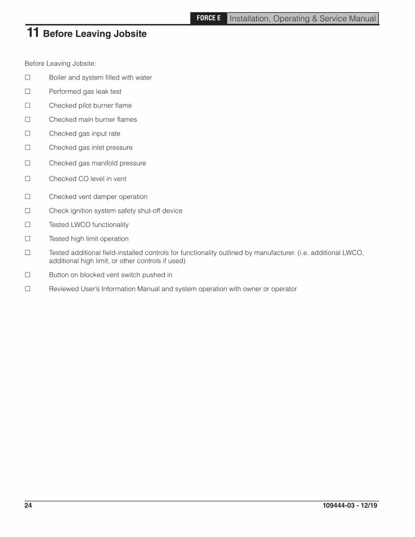
Before Leaving Jobsite:
Boiler and system filled with water
Performed gas leak test
Checked pilot burner flame
Checked main burner flames
Checked gas input rate
Checked gas inlet pressure
Checked gas manifold pressure
Checked CO level in vent
Checked vent damper operation
Check ignition system safety shut-off device
Tested LWCO functionality
Tested high limit operation
Tested additional field-installed controls for functionality outlined by manufacturer. (i.e. additional LWCO, additional high limit, or other controls if used)
Button on blocked vent switch pushed in
Reviewed User’s Information Manual and system operation with owner or operator
25
FORCE E Installation, Operating & Service Manual
109444-03 - 12/19
12 Service and Maintenance
Important Product Safety Information:Refractory Ceramic Fiber Product
WARNING
Some boiler components use materials that contain refractory ceramic fibers (RCF). RCF has been classified as a possible human carcinogen. When exposed to elevated temperatures, RCF may change into crystalline silica, a known carcinogen. When disturbed as a result of servicing or repair, these substances become airborne and, if inhaled, may be hazardous to your health. Avoid breathing RCF particulates and dust.
Precautionary Measures:
• Do not handle RCF parts or attempt any service or repair work involving RCF without wearing the following protective gear:
1. A properly fitting National Institute for Occupational Safety and Health (NIOSH)-certified air-purifying respirator with a filter efficiency of at least 95%. Respirator should also include a full facepiece when handling used RCF. Other types of respirators may be required depending on site conditions. Current NIOSH recommendations may be found on the NIOSH website http://www.cdc.gov/niosh/homepage.html. NIOSH-approved manufacturers, respirators and associated user instructions are listed on the NIOSH website.
2. Long sleeved, loose fitting clothing that is sufficiently tight around potential entry points for RCF dust.
3. Gloves.4. Eye protection, such as goggles, safety glasses with side shields, or full facepiece.
• Take steps to assure adequate ventilation.• Handle RCF carefully to minimize airborne dust. Use hand tools whenever possible.• Dampen used RCF with light water spray prior to removal to prevent airborne dust.• Do not use compressed air or dry sweeping for clean-up. Frequently clean work area with a
vacuum or by wet sweeping to minimize debris accumulation.• Vacuum work clothes before leaving work area. Wash work clothes separately from other
laundry and rinse washing machine after use to avoid contaminating other clothes.• Wash all exposed body areas gently with soap and water after contact.• Discard used RCF components by sealing in an airtight plastic bag or container. Refer to
local, regional, state or provincial regulations to identify applicable disposal requirements.
First Aid Procedures:
• Eye contact: Flush with water for at least 15 minutes. Do not rub eyes. Seek immediate medical attention if irritation persists.
• Skin contact: Wash affected area gently with soap and water. Do not rub or scratch affected skin. Seek immediate medical attention if irritation persists.
• Nose and throat contact: If these become irritated, leave the area and move to a location with clean fresh air. Drink water and blow nose. Seek immediate medical attention if symptoms persist.
26
FORCE E Installation, Operating & Service Manual
109444-03 - 12/19
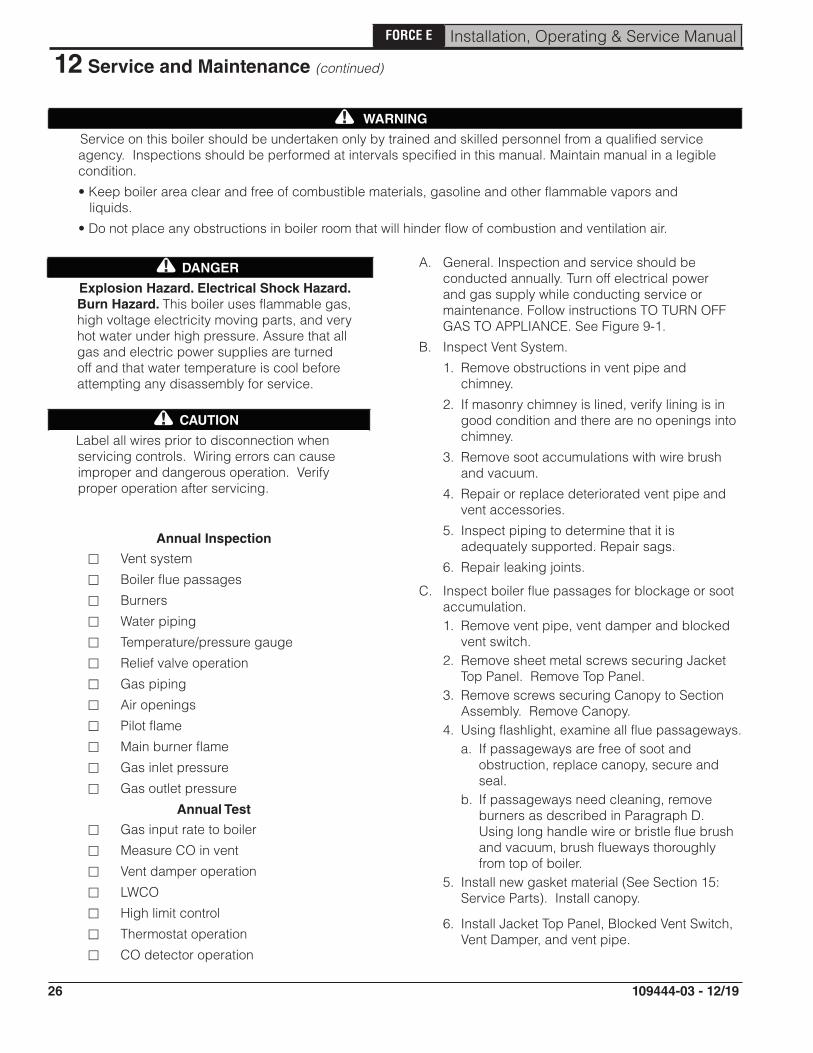
DANGER
Explosion Hazard . Electrical Shock Hazard . Burn Hazard . This boiler uses flammable gas, high voltage electricity moving parts, and very hot water under high pressure. Assure that all gas and electric power supplies are turned off and that water temperature is cool before attempting any disassembly for service.
CAUTION
Label all wires prior to disconnection when servicing controls. Wiring errors can cause improper and dangerous operation. Verify proper operation after servicing.
Annual Inspection
Vent system
Boiler flue passages
Burners
Water piping
Temperature/pressure gauge
Relief valve operation
Gas piping
Air openings
Pilot flame
Main burner flame
Gas inlet pressure
Gas outlet pressure
Annual Test
Gas input rate to boiler
Measure CO in vent
Vent damper operation
LWCO
High limit control
Thermostat operation
CO detector operation
A. General. Inspection and service should be conducted annually. Turn off electrical power and gas supply while conducting service or maintenance. Follow instructions TO TURN OFF GAS TO APPLIANCE. See Figure 9-1.
B. Inspect Vent System.
1. Remove obstructions in vent pipe and chimney.
2. If masonry chimney is lined, verify lining is in good condition and there are no openings into chimney.
3. Remove soot accumulations with wire brush and vacuum.
4. Repair or replace deteriorated vent pipe and vent accessories.
5. Inspect piping to determine that it is adequately supported. Repair sags.
6. Repair leaking joints.
C. Inspect boiler flue passages for blockage or soot accumulation. 1. Remove vent pipe, vent damper and blocked
vent switch.2. Remove sheet metal screws securing Jacket
Top Panel. Remove Top Panel.3. Remove screws securing Canopy to Section
Assembly. Remove Canopy.4. Using flashlight, examine all flue passageways.
a. If passageways are free of soot and obstruction, replace canopy, secure and seal.
b. If passageways need cleaning, remove burners as described in Paragraph D. Using long handle wire or bristle flue brush and vacuum, brush flueways thoroughly from top of boiler.
5. Install new gasket material (See Section 15: Service Parts). Install canopy.
6. Install Jacket Top Panel, Blocked Vent Switch, Vent Damper, and vent pipe.
12 Service and Maintenance (continued)
WARNING
Service on this boiler should be undertaken only by trained and skilled personnel from a qualified service agency. Inspections should be performed at intervals specified in this manual. Maintain manual in a legible condition.
• Keep boiler area clear and free of combustible materials, gasoline and other flammable vapors and liquids.
• Do not place any obstructions in boiler room that will hinder flow of combustion and ventilation air.
!
!
!

27
FORCE E Installation, Operating & Service Manual
109444-03 - 12/19
D. Clean Main Burners and Firebox.1. To remove burners for cleaning, changing
orifices, or repairs:a. Remove Jacket Front Panel.b. Disconnect pilot tubing at gas valve.c. Disconnect 3-wire plug at the gas valve. d. Remove wires to flame roll-out switch.e. Disconnect ignitor sensor cable at boiler
control.f. Remove the burner access panel.g. Mark the location of the pilot main burner on
the manifold if the marking on manifold is missing.
h. Hold burner at throat. Lift front of burner to clear orifice. Pilot burner can only be removed by lifting the burner adjacent to its right first.
2. Brush top of burners with a soft bristle brush. Vacuum burners.
3. Check orifices. Drilled passageways must be free of lint or dirt.
4. Vacuum tip of Pilot Burner.5. Clean firebox by vacuuming. Exercise care not
to damage base insulation.6. Install burners by reversing procedure used
to remove burners. Make sure burner with pilot assembly is in same location as original installation.
WARNING
Be careful handling pilot tubing. Do not crimp or crack gas pilot tube. Leaking pilot tubing could result in serious injury, or substantial property damage.
Check burners to see that they are located properly in slot at rear of burner tray. Reinstall burner access panel. Reconnect flame roll-out switch wires, pilot gas supply, or pilot lead.
7. Connect pilot gas supply, igniter/sensor wire, and ground wire at Boiler Control.
8. Install Burner Access Panel. Connect Flame Rollout Switch wires.
E. Inspect Water Piping
1. Check all system piping for leaks.
2. Repair any leaks before placing back into service.
12 Service and Maintenance (continued)
F. Inspect Temperature/Pressure Gauge 1. Water temperature needle should move with
variation in water temperature. 2. Pressure needle should move with variation in
pressure. 3. Replace gauge if needed.G. Operate Safety Relief Valve 1. When manually operating the relief valve,
water will discharge. Take precautions to avoid contact with hot water and avoid water damage. Inspect relief valve and lift lever to verify flow.
2. If relief valve leaks or will not seat properly, replace relief valve.
H. Inspect Gas Piping 1. Sniff around boiler area for indication of gas
leak. 2. Locate leaks using approved gas detector,
a non corrosive leak detector fluid or other approved leak detection methods.
3. Repair any leaks before placing back into service and retest.
I. Inspect Air Openings 1. Keep boiler area clear of combustible
materials. 2. Remove any obstructions in boiler room
that will hinder flow of combustion and ventilation air and dilution air.
J. Follow "Operating Instructions" outlined in Figure 9-1.
K. Inspect Pilot Flame See "Start-up and Checkout - Check Pilot Burner
Flame"L. Inspect Main Burner Flames See "Start-up and Checkout - Check Main Burner
Flame"M. Check gas inlet pressure See "Start-up and Checkout - Check gas inlet
pressure"N. Check gas outlet pressure See "Start-up and Checkout - Check gas outlet
pressure"O. Check Gas Input Rate to Boiler See "Start-up and Checkout - Check Gas Input to
Boiler"P. Measure CO in vent. See "Start-up and Checkout -
Measure Carbon Monoxide Level".
!
28
FORCE E Installation, Operating & Service Manual
109444-03 - 12/19
12 Service and Maintenance (continued)
Q. Test Vent Damper Operation Vent damper must be in open position when main
burners are operating.R. Test Functionality of LWCO See "Start-up and Checkout - Check LWCO
Functionality.S. Check High Limit Control See " Start-up and Checkout - Check High Limit
Control".T. Check Thermostat Operation See "Start-up and Checkout - Check Thermostat
Operation"U. Check CO detector operation (if available).
V. Lubrication. There are no parts requiring lubrication by service technician or owner. Circulator bearings are water lubricated.
W. If remodeling has occurred, verify combustion air supply is adequate.

29
FORCE E Installation, Operating & Service Manual
109444-03 - 12/19
13 How It Works
1/2
Hydrostat 3200
FORCE E boilers are equipped with Hydrostat 3200 and Honeywell S8610M Ignition module. Hydrostat 3200 contains features such as high limit switch, LWCO and circulator relay. Energy is saved by using a thermal target feature which adjusts boiler target temperature depending on heat required.
Honeywell S8610M provides ignition control.Dual sensor for boiler temperature control and protection against potentially damaging low water conditions in boiler. In event of low water condition, “LOW WATER” LED will turn on and control will shutdown burner. Can be configured for auto reset or manual reset LWCO.When thermostat calls for heat, Hydrostat 3200 starts system circulator, checks safety limits, and activates vent damper.When vent damper is opened completely, ignition module opens pilot valve and activates ignition spark.
Honeywell S8610M Ignition Module
Ignition module will sense pilot flame. Once pilot flame is established, ignition module opens gas valve and main burners will ignite.When thermostat is satisfied, ignition module turns off gas valve, deactivates damper, and deactivates circulator.Hyrdostat 3200 indicates boiler status. Indicator lights provide assistance with troubleshooting. See Hydrostat 3200 installation instructions and operating manual for more information.Honeywell S8610M indicator lights provide assistance with troubleshooting. See Table 10-4 for more information.
3Draft Hood Provides adequate dilution air and ensures proper draft for boiler operation.
Blocked Vent Switch If vent becomes blocked, switch will open (requiring manual reset) and cause burners to shut down.
4 Flame Roll-Out SwitchIf flames roll out of burner tubes, switch will open (requiring replacement) and cause burners to shut down. If switch trips, determine cause of flame roll-out.
5 Gas Valve Regulates gas flow to boiler.
6 Pilot Provides ignition source for burner lighting.
7 Vent Damper Closes during off cycles to reduce heat loss from house to vent.

30
FORCE E Installation, Operating & Service Manual
109444-03 - 12/19
3
1
2
5
4 6
7
(On rear of boiler)
Rear of Boiler
3
13 How It Works (continued)
31
FORCE E Installation, Operating & Service Manual
109444-03 - 12/19
14 Troubleshooting
A. Before Troubleshooting
When troubleshooting boiler, keep in mind:
1. Troubleshooting should be completed by a professional heating technician.
2. Before seeking technical assistance, the servicing technician should have an electrical meter and gas pressure gauge available for use.
3. Check electrical connections on boiler before proceeding (see Figure 8-1 and Figure 8-2).
4. Ensure 120VAC power polarity is correct, and boiler is properly grounded.
5. Controls are tested during manufacturing process. Defective control is least likely cause of failure.
B. Temperature Limit/LWCO Control
Refer to the HydroStat 3200 Installation Instructions and Operating Manual included with these instructions.
C. Electronic Ignition Module (see Figure 14-1)
U.S. Boiler Company, Inc.P.O. Box 3020Lancaster, PA 176041-888-432-8887www.usboiler.net

32
FORCE E Installation, Operating & Service Manual
109444-03 - 12/19
14 Troubleshooting (continued)Start
Before troubleshooting,familiarize yourself with the
Startup and Checkoutprocedures.
Note: "Call for heat" 24 VAC supply is connected to the 24 V terminal on the control.
Turn gas supply off.Turn thermostat(controller) to"Call For Heat".
Power tomodule? (24 V
normal)
Yes
NoCheck line voltage power, low voltage transformer, limit controller, thermostat (controller) and wiring. Also,check air proving switch on combustion air blower system (if used) and the the vent damper end switch (if used)is made.
No
30 secondprepurge
delay? (S8670Only)
Replace S8670
Yes
NoSpark
across ignitor/sensor gap?
Pull ignition lead andcheck spark at module. Spark OK? No
Yes
Replace module
Check ignition cable, ground wiring, ceramic insulator and spark gap and correct.Check boot of the ignition cable for signs of melting or buckling. Take protective action to shield cable and bootfrom excessive temperatures.
Yes
Turn gas supply on andrecycle "Call For Heat"
Pilot burnerlights?
Yes
No
Check that all manual gas valves are open, supply tubing and pressures are good, and pilot burner orifice is notblocked (pilot gas flowing).Check electrical connections between module and pilot operator on gas control.Check for 24 VAC across PV-MV/PV terminals on module, if voltage is OK, replace gas control. If not, replacemodule.Note: It may be necessary to recycle the "Call For Heat" more than once to clear the pilot supply tubes of air.
Spark stopswhen pilot
is lit?
Yes
No
Note: If control goes into lockout or retry delay, reset the "Call For Heat".Check continuity of ignition cable and ground wire.Clean flame rod.Check electrical connections between flame rod and module.Check for cracked ceramic flame rod insulator.Check that pilot flame covers flame rod and is steady and blue.Adjust pilot flame.If problem persists, replace module.
Main burnerlights? No
Yes
Check for 24 VAC across PV-MV/PV terminals on module. If no voltage, replace module.Check electrical connections between module and gas control including safety controls wired in the circuit. Ifokay, replace gas control.
System runsuntil "Call ForHeat" ends?
No
Note: If control goes into lockout or retry delay, reset the "Call For Heat".Check continuity of ignition cable and ground wire.Note: If ground is poor or erratic, shutdowns may occur occasionally even though operation is normal at the timeof checkout.Check that pilot flame covers flame rod and is steady and blue. Pilot flame must not be moving around due tooutside air flows, etc.Adjust pilot flame. Check gas pressure meets appliance specifications while appliance main burner is on and allother gas appliances on the supply are operating at full rate.If checks are okay, replace module.
Yes
"Call For Heat" ends
Systemshuts off?
No
Yes
Check for proper thermostat (controller) operation.Remove MV lead at module. If valve closes, recheck temperature controller and wiring. If not, replace gas control.
Repeat procedure untiltrouble free operation
is obtained.
Figure 14-1: Troubleshooting Guide, Honeywell Electronic Ignition (EI)

33
FORCE E Installation, Operating & Service Manual
109444-03 - 12/19
Key No. DescriptionPart Number [Quantity]
FORCE02E FORCE03E FORCE04E FORCE05E FORCE06E FORCE07E FORCE08E FORCE09E
1A Section Assembly 109871-02 [1]
109871-03 [1]
109871-04 [1]
109871-05 [1]
109871-06 [1]
109871-07 [1]
109871-08 [1]
109871-09 [1]
1B Canopy Gasket 109943-01 [1]
1C Canopy 109944-02 [1]
109944-03 [1]
109944-04 [1]
109944-05 [1]
109944-06 [1]
109944-07 [1]
109944-08 [1]
109944-09 [1]
Not Shown
Blocked Vent Switch (see Figure 5-1) 109942-01 [1]
All FORCETM E Series Service Parts may be obtained by contacting your local Ferguson branch.
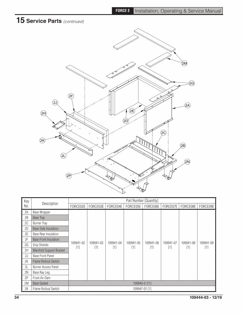
15 Service Parts
34
FORCE E Installation, Operating & Service Manual
109444-03 - 12/19
Key No. Description
Part Number [Quantity]FORCE02E FORCE03E FORCE04E FORCE05E FORCE06E FORCE07E FORCE08E FORCE09E
2A Base Wrapper
109941-02 [1]
109941-03 [1]
109941-04 [1]
109941-05 [1]
109941-06 [1]
109941-07 [1]
109941-08 [1]
109941-09 [1]
2B Base Tray2C Burner Tray2D Base Side Insulation2E Base Rear Insulation2F Base Front Insulation2G Drip Shields2H Manifold Support Bracket2J Base Front Panel
2K Flame Rollout Switch
2L Burner Access Panel2N Base Ray Leg 2P Front Air Dam2M Base Gasket 109940-0 1[1]2K Flame Rollout Switch 109947-01 [1]
15 Service Parts (continued)
35
FORCE E Installation, Operating & Service Manual
109444-03 - 12/19
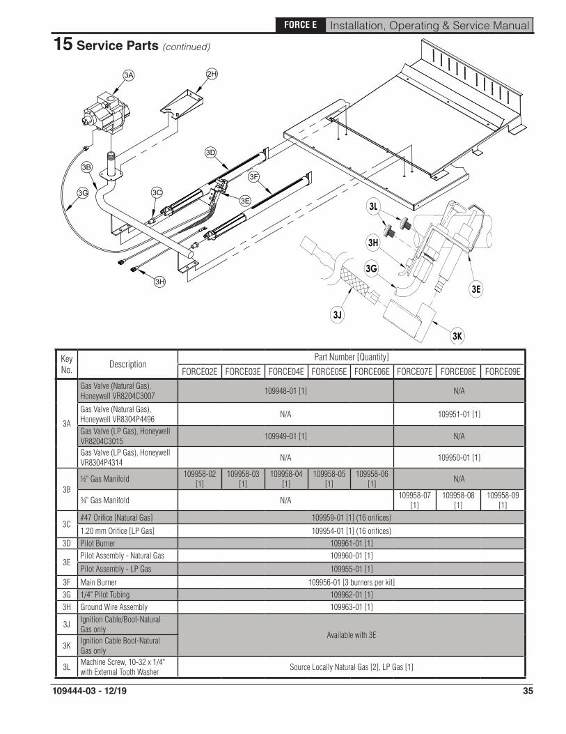
Key No. Description
Part Number [Quantity]
FORCE02E FORCE03E FORCE04E FORCE05E FORCE06E FORCE07E FORCE08E FORCE09E
3A
Gas Valve (Natural Gas), Honeywell VR8204C3007 109948-01 [1] N/A
Gas Valve (Natural Gas), Honeywell VR8304P4496 N/A 109951-01 [1]
Gas Valve (LP Gas), Honeywell VR8204C3015 109949-01 [1] N/A
Gas Valve (LP Gas), Honeywell VR8304P4314 N/A 109950-01 [1]
3B½" Gas Manifold 109958-02
[1]109958-03
[1]109958-04
[1]109958-05
[1]109958-06
[1] N/A
¾" Gas Manifold N/A 109958-07 [1]
109958-08 [1]
109958-09 [1]
3C#47 Orifice [Natural Gas] 109959-01 [1] (16 orifices)
1.20 mm Orifice [LP Gas] 109954-01 [1] (16 orifices)3D Pilot Burner 109961-01 [1]
3EPilot Assembly - Natural Gas 109960-01 [1]
Pilot Assembly - LP Gas 109955-01 [1]
3F Main Burner 109956-01 [3 burners per kit]3G 1/4" Pilot Tubing 109962-01 [1]3H Ground Wire Assembly 109963-01 [1]
3J Ignition Cable/Boot-Natural Gas only
Available with 3E3K Ignition Cable Boot-Natural
Gas only
3L Machine Screw, 10-32 x 1/4" with External Tooth Washer Source Locally Natural Gas [2], LP Gas [1]
15 Service Parts (continued)

36
FORCE E Installation, Operating & Service Manual
109444-03 - 12/19
Key No. DescriptionPart Number [Quantity]
FORCE02E FORCE03E FORCE04E FORCE05E FORCE06E FORCE07E FORCE08E FORCE09E4A Hydrostat 3200 LWCO/High Limit 109952-01 [1]4B Honeywell S8610M EI Module 109945-01 [1]
15 Service Parts (continued)

37
FORCE E Installation, Operating & Service Manual
109444-03 - 12/19
Key No. Description
Part Number [Quantity]
FORCE02E FORCE03E FORCE04E FORCE05E FORCE06E FORCE07E FORCE08E FORCE09E5A Wrap-around Jacket Panel Not available
5B Jacket Vestibule Panel
109618-02 [1]
109618-03 [1]
109618-04 [1]
109618-05 [1]
109618-06 [1]
109618-07 [1]
109618-08 [1]
109618-09 [1]
5C Rear Discharge Chute
5D Top Jacket Panel
5E Front Door Jacket Panel
5F Tie Bar Jacket Panel
15 Service Parts (continued)
38
FORCE E Installation, Operating & Service Manual
109444-03 - 12/19
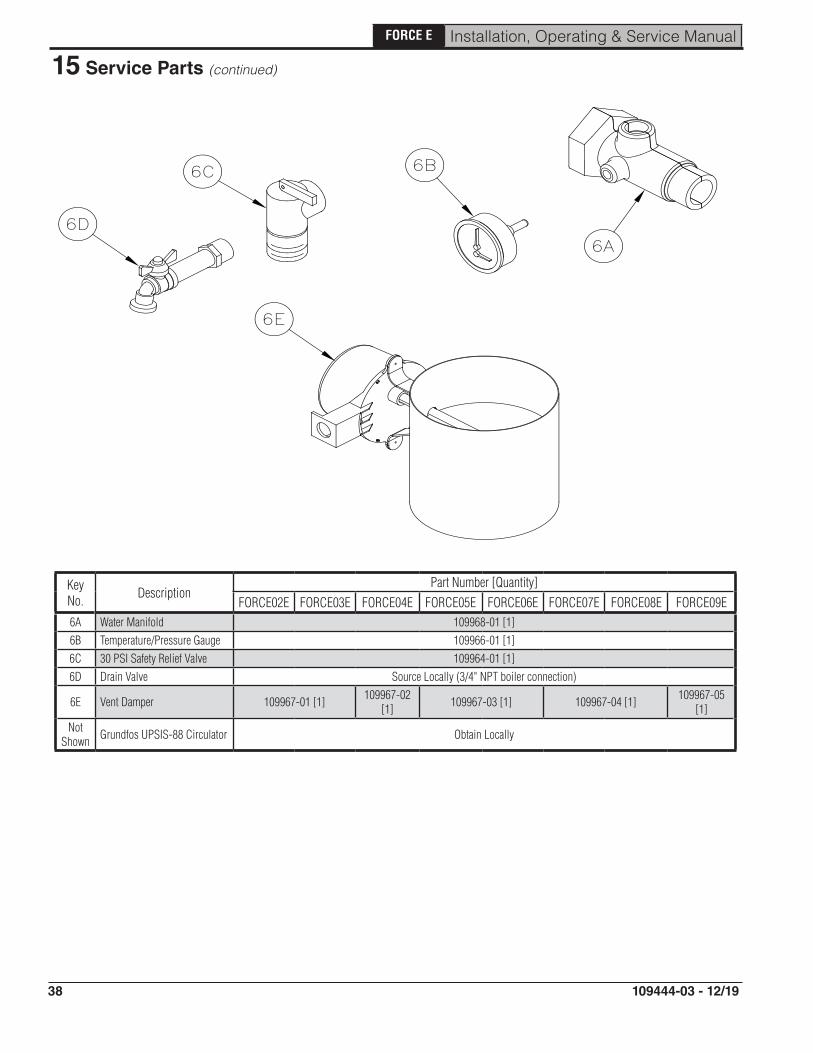
Key No. Description
Part Number [Quantity]FORCE02E FORCE03E FORCE04E FORCE05E FORCE06E FORCE07E FORCE08E FORCE09E
6A Water Manifold 109968-01 [1]6B Temperature/Pressure Gauge 109966-01 [1]6C 30 PSI Safety Relief Valve 109964-01 [1]6D Drain Valve Source Locally (3/4" NPT boiler connection)
6E Vent Damper 109967-01 [1] 109967-02 [1] 109967-03 [1] 109967-04 [1] 109967-05
[1]Not
Shown Grundfos UPSIS-88 Circulator Obtain Locally
15 Service Parts (continued)
39
FORCE E Installation, Operating & Service Manual
109444-03 - 12/19
15 Service Parts (continued)
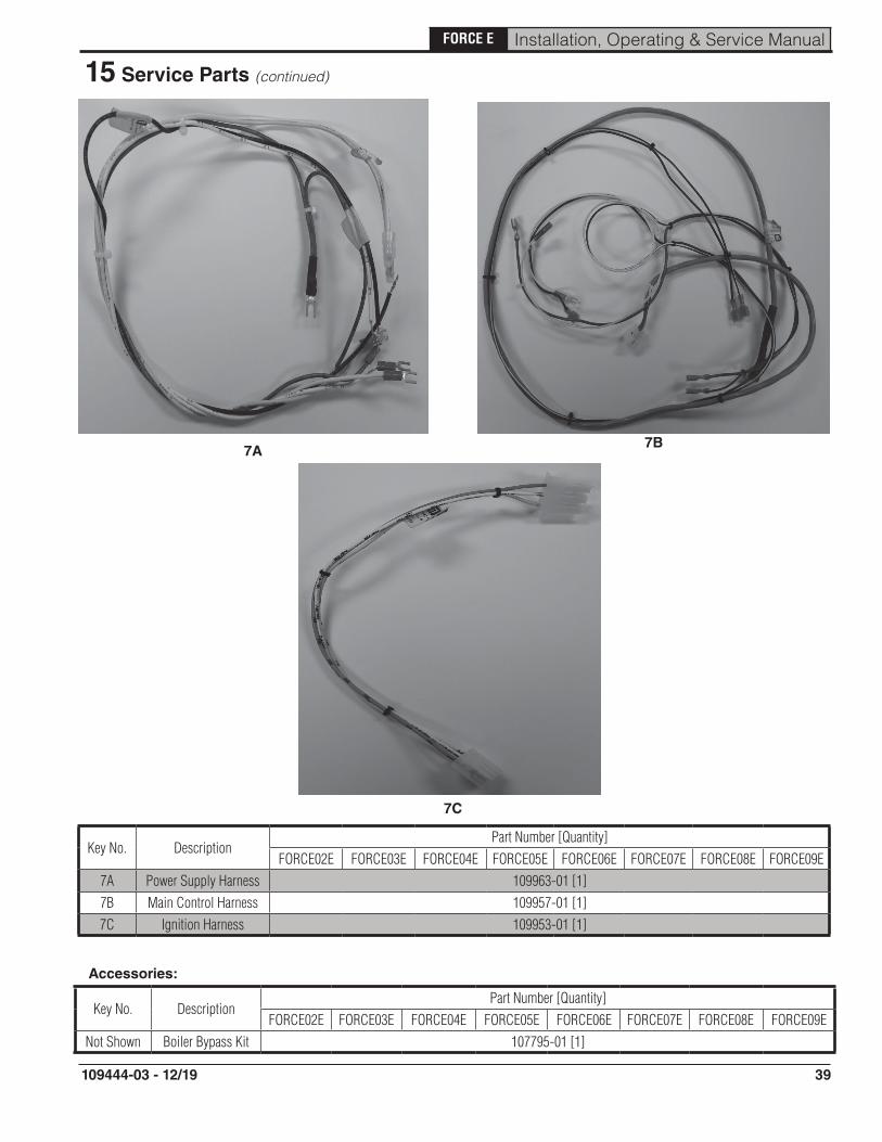
Key No. DescriptionPart Number [Quantity]
FORCE02E FORCE03E FORCE04E FORCE05E FORCE06E FORCE07E FORCE08E FORCE09E7A Power Supply Harness 109963-01 [1]7B Main Control Harness 109957-01 [1]7C Ignition Harness 109953-01 [1]
Key No. DescriptionPart Number [Quantity]
FORCE02E FORCE03E FORCE04E FORCE05E FORCE06E FORCE07E FORCE08E FORCE09ENot Shown Boiler Bypass Kit 107795-01 [1]
Accessories:
7A 7B
7C

40
FORCE E Installation, Operating & Service Manual
109444-03 - 12/19
A. If boiler is used in connection with refrigeration systems, boiler must be installed with chilled medium piped in parallel with the heating boiler using appropriate valves to prevent chilled medium from entering boiler. See Figure A-1. Also consult Residential Hydronic Heating Installation and Design I=B=R Guide.
Appendix: Combination Refrigeration/ Heating System
WaterChiller
Shut-offvalves
Shut-offvalves
ExpansionTank
CirculatorSupply main tocombined heating
& cooling system
Return main fromcombined heating& cooling system
HeatingBoiler
B. If boiler is connected to heating coils located in air handling units where they may be exposed to refrigerated air, boiler piping must be equipped with flow control valves or other automatic means to prevent gravity circulation of boiler water during operation of cooling system.
Figure A-1: Isolated Boiler from Refrigeration System
41
FORCE E Installation, Operating & Service Manual
109444-03 - 12/19
Appendix: Low Return Water Temperatures
Thermal Shock:
Cast iron boilers are very robust. 110oF and below return water temperatures will not cause thermal shock to castings.
Condensation is a different matter:
Cast iron boilers will tolerate intermittent periods of condensation, but are not designed for extended condensation periods. Water temperatures below 120oF cause condensation that damage cast iron, burners and other components. This is not unique to boiler design. All cast iron boilers act the same way.
Typical high temperature [170oF and higher] fin tube radiation heating systems will have short condensation cycles in 'shoulder' seasons, early and late parts of the heating season. Short term condensing during these heating season 'shoulders' is unlikely to cause problems.
Larger volume systems during the 'shoulder' heating seasons or systems with aggressive set back or low temperature systems will cause extended condensation periods that will shorten boiler life.
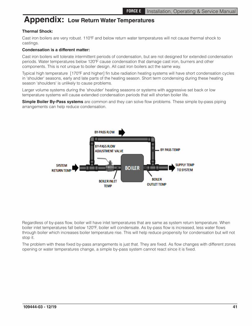
Simple Boiler By-Pass systems are common and they can solve flow problems. These simple by-pass piping arrangements can help reduce condensation.
Regardless of by-pass flow, boiler will have inlet temperatures that are same as system return temperature. When boiler inlet temperatures fall below 120oF, boiler will condensate. As by-pass flow is increased, less water flows through boiler which increases boiler temperature rise. This will help reduce propensity for condensation but will not stop it.
The problem with these fixed by-pass arrangements is just that. They are fixed. As flow changes with different zones opening or water temperatures change, a simple by-pass system cannot react since it is fixed.

42
FORCE E Installation, Operating & Service Manual
109444-03 - 12/19
Appendix: Low Return Water Temperatures (continued)
Primary-Secondary Pumping:
Kit includes all fittings, pump, sensor and instructions for installation.
This is an improvement over simple by-pass piping to reduce condensation.
Again this is a fixed system. It can not adapt to variations in temperature and flow.
Best Alternative: System by-pass kit [part number 107795-01] that addresses these situations.
A strap on temperature sensor measures boiler inlet temperatures. This temperature signal is sent to a variable speed pump that will ensure boiler inlet temperatures are always greater than the factory by-pass kit set point of 120oF.
43
FORCE E Installation, Operating & Service Manual
109444-03 - 12/19

44
FORCE E Installation, Operating & Service Manual
109444-03 - 12/19