
Installation of Heated Grips on 2009 Kawasaki Voya
12
1 March 14, 2010 Installation of Heated Grips, 2009 Kawasaki Voyager After spending many years riding a BMW with heated grips, I realize how important it is to keep the hands warm, whether it is just rainy, or truly cold. Therefore putting heated grips on my new Voyager was a priority. After doing research on various heated grips, I narrowed my choice down to the “Hot Grips”brand available at: www.hotgrips.com Part of the reason why I decided on Hot Grips, is because the company owner “ Jim Hollander”was very quick to answer my questions, and provided all the information that I needed. In other words he gave me the “warm fuzzy feeling”about his product. (I wish other suppliers would do that). I ordered model “525-100”with the optional chrome end caps, and the 2 part epoxy (optional). (If you want the chrome end caps and Epoxy you need to specify when ordering.) The grips in this kit are 5-1/4" overall length and meant for 1" handlebars with a 1-1/8" throttle sleeve. The Kit contains: Left and right heated grip (with optional chrome end caps). Resistor for the low temperature setting. High/Low toggle switch Fuse holder (not shown) Instructions Not shown is the optional 2 part epoxy that I also bought from Hot Grips. Below; I have detailed how I installed the grips. Hopefully my experience will help others installing grips. Please make sure that you follow the instructions provided by “Hot Grips” . Remove the Factory Grips Before removing the factory grips, the “ chromed plastic”grip end caps need to be removed. The chromed plastic ends are threaded on, but have “ left hand”threads, which means to unscrew you need to turn them clockwise. (The opposite way that you would normally unscrew something) To do that I recommend using, either a rubber strap wrench, or a sheet of thin rubber used as you would to loosen the lid of a jar. Once I had the end caps off, I used a sharp utility knife to cut through, and peel off the factory rubber grips. (They are only about 1/8”thick so it’ s easy to do.) With the rubber grips off, I removed the chromed ring that is adjacent to the left switch housing. The left ring will come off, with a gentle pull, but the throttle side ring will need to be cut off, as it’ s pressed on. It’ s easy to do; I cut it off using wire side cutters (see picture on page 3 below). Factory left and right Grips
Transcript of Installation of Heated Grips on 2009 Kawasaki Voya
1
March 14, 2010Installation of Heated Grips, 2009 Kawasaki Voyager
After spending many years riding a BMW with heated grips, I realize how important it is to keep thehands warm, whether it is just rainy, or truly cold. Therefore putting heated grips on my newVoyager was a priority.
After doing research on various heated grips, I narrowed my choice down to the “Hot Grips”brandavailable at: www.hotgrips.comPart of the reason why I decided on Hot Grips, is because the company owner “Jim Hollander”wasvery quick to answer my questions, and provided all the information that I needed. In other wordshe gave me the “warm fuzzy feeling”about his product. (I wish other suppliers would do that).
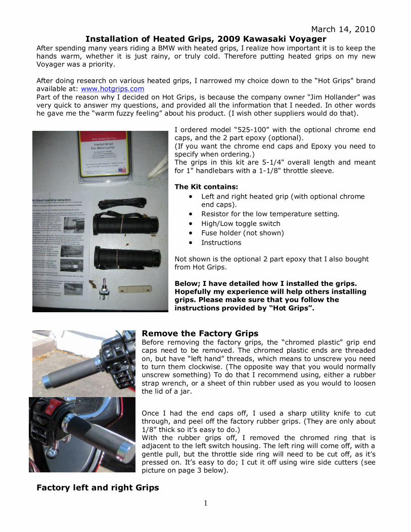
I ordered model “525-100”with the optional chrome endcaps, and the 2 part epoxy (optional).(If you want the chrome end caps and Epoxy you need tospecify when ordering.)The grips in this kit are 5-1/4" overall length and meantfor 1" handlebars with a 1-1/8" throttle sleeve.
The Kit contains:
Left and right heated grip (with optional chromeend caps).
Resistor for the low temperature setting.
High/Low toggle switch
Fuse holder (not shown)
Instructions
Not shown is the optional 2 part epoxy that I also boughtfrom Hot Grips.
Below; I have detailed how I installed the grips.Hopefully my experience will help others installinggrips. Please make sure that you follow theinstructions provided by “Hot Grips”.
Remove the Factory GripsBefore removing the factory grips, the “chromed plastic”grip endcaps need to be removed. The chromed plastic ends are threadedon, but have “left hand”threads, which means to unscrew you needto turn them clockwise. (The opposite way that you would normallyunscrew something) To do that I recommend using, either a rubberstrap wrench, or a sheet of thin rubber used as you would to loosenthe lid of a jar.
Once I had the end caps off, I used a sharp utility knife to cutthrough, and peel off the factory rubber grips. (They are only about1/8”thick so it’s easy to do.)With the rubber grips off, I removed the chromed ring that isadjacent to the left switch housing. The left ring will come off, with agentle pull, but the throttle side ring will need to be cut off, as it’spressed on. It’s easy to do; I cut it off using wire side cutters (seepicture on page 3 below).
Factory left and right Grips

2
After removing thechromed end cap, andthe factory rubbergrips.
The chromed plasticring next to the switchhousing needs to be cutoff.
Note all the ridges onthe sleeve, all theseexcept one ridge needto be filed off.
1. Prepare left handle bar for grip installationThe left handle bar is pretty easy to prepare, first I cleaned any glue from the bar, and then gentlytest fit the left grip, be very careful here as it needs to slide on easily.As per the instructions, “Do not force the grip on with anything greater than gentle handforce”. Remember after the test fit you need to take it off again. (You could also crack the heatedgrip if it’s too tight).If you find it too tight, as I did sand the bar using sand paper until it slides on and off easily. Onmy bike I used an 80 grit sand paper, and it took approx 20 minutes to get a good fit.
Using a hack saw I cut the threads offthe end of the left bar.

3
2. Prepare throttle sleeve for grip installationThe plastic throttle sleeve needs to be filed to make room for the new grip. As this is easieraccomplished on a work bench I opened up the throttle housing and removed the sleeve.
To remove the throttle sleeve, I first put a towel overmy tank to protect the paint work in case the housingdropped, then I un-screwed the 2 screws (C) in thechrome cap (B), and then removed screw (D).The two halves of the housing then came apart, then Itook the 2 throttle cables off the throttle sleeve andthe sleeve slid off the handle bar.
Cut off the plastic Chrome ring.
Using a hacksaw I cut off thethreads
I used a very coarse metal file toremove all the ridges except onefrom the sleeve.

4
When filing be very careful not to file through the throttle sleeve, I made sure that I filedon a flat plain, not on an angle.Attacking one ridge at a time I filed off all the longitudinal ridges except one.(if you look inside the new “Hot Grip”you will see grooves, by leaving one ridge on the sleeve itnicely locks to the sleeve.)
In addition to filing the longitudinal ridges, I needed to lightly file the raised area around the end ofthe sleeve, close to the end that had the thread. Also just to the right of the file in the pictureabove, there is a raised area that needs to be filed.Test fit the new hot grip; it needs to slide up to the raised area shown with the arrow in the abovepicture.
The finished throttle sleeve, ready to be re-installed

5
I then reinstalled the sleeve in thehousing. Put both throttle cablesback on and tightened all thehousing screws.You can see the one ridge that Ileft on the sleeve.
3. Epoxy on the new grips.When test fitting the new grips, I decided that the best position for the power wires is straightdown or a 6 o-clock position.I mixed the high heat 2 part epoxy, and applied it using a stick (about the size of a pencil) to theentire throttle sleeve, and then slowly slid on the throttle grip, cleaning up the excess epoxy as thegrip slid on. I then repeated the process on the left bar. I found the left bar did not need as muchepoxy as the throttle side.
Installed throttle grip.

6
Installed left grip.
The day I installed the grips the temperature was just below freezing, so as per the instructions Iconnected them up to a 12 volt power source for about 45 minutes, the heat helps to set theepoxy.
4. Connect the WiringLeaving a couple ofinches slack at thethrottle grip, I ran thewires from both gripsalong the handle barsand neatly secured withcable zip ties.
Just in front of thehandlebar clamps, Ithen connected thewires from both grips toone main power linerunning to the switch/resistor and Aux groundconnection.

7
Wiring connections are always a weak point. When making wire connections some people liketo solder, however years ago, I found out that solder joints often break due to the vibration on therigid solder joint. The solution that I found to work better, is a good crimp connector filled withsilicone. The silicone not only helps to seal out moisture, but also acts as a vibration dampener.
On a board I squeeze out a lineof silicone, and then fill theconnector by scooping it in thesilicone.Then insert the wire into thecrimp connector and crimp.
Once the silicone is dry I havea moisture proof, vibrationresistant connection.
Above is the wiring diagram I used to connect the grips.
To connect the grips all I needed to do was remove the left hand speaker grill and speaker, and theleft storage box. This provided access to the AUX power connections, and allowed room to mountthe resistor and install the switch.

8
Using a 4mm hex wrench,remove the 2 bolts on the leftspeaker grill.
Remove the 4 Philips screws that hold in the leftspeaker and speaker box, lift out the speaker andun-plug the connectors on the rear of the speaker.
Pull out the speaker box, the 2 speaker wires willslide through the hole in the back.

9
Next unlock the left storage box and remove the 3Philips screws. Gently pull out the box allowing the2 IPod wire connections to go through the hole inthe back of the box. A rubber grommet needs tobe removed before the plugs will slip through thehole.
With the speaker assemblyand storage box removed,you can reach up and find the2 Aux power connectors,which are on the top left ofthe radio.These connectors take a male“pin”type plug (as shown inthe “silicone”picture on page7)The Brown and Blue wire isthe positive, and the Blackyellow is the negative(ground)
I attached the low heatresistor to the metal bar thatis part of the driving lightbracket, using nylon zip ties.
On to one of the wires running from the grips, I crimped a male pin type connector, and plugged itdirectly to the Black and yellow wire Aux ground connector.

10
After resistor mounted.
Next to the left speaker opening Idrilled a ½”hole in the fairing toaccommodate the high/low switch.
The other switch shown is a powerswitch for my “Sirius”radio.
Switch Installed.

11
The High/low toggle switch does not come with a water proofcover, this I purchased from an auto parts store. It just screwson over the toggle, and results in a weather proof switch thatblends in with the fairing.
Using the supplied fuse, I crimped on a male pin plug, and a female spade plug. The male pin plugwent into the “Brown and Blue”Aux wire (as shown on page 9), and the female spade plug wasplugged onto the center connector on the back of the toggle high/low switch.
As I wanted the toggle switch to be in the lowposition when it is in the down position, usinga wire with crimped female spade terminalson each end, I connected a wire from the topterminal on the back of the toggle switch tothe resistor.
I then created another wire with a crimpedfemale spade terminal to the other end of theresistor and ran this wire back to the switch,and connected it along with the positive wirefrom the grips to the bottom connector on theback of the toggle switch.

12
It was time to test the grips; the switch center position is off, down is low heat and up is high heat.
After I determined the grips work, I reinstalled the storage box, being sure to reinsert the IPodconnections and rubber grommet in the back of the box, and then fasten in place with the 3 Philipsscrews.
Next I installed the speaker box, inserting the speaker wires through the back, and plugged themon the speaker (note the 2 speaker wires have different sized plugs so you can’t mix up the wires).Secure the speaker and speaker box in place using the 4 Philips screws. Then install the chromespeaker grill using the 2 4mm hex bolts.
Now it’s time to enjoy the “heat”.
Julian [email protected]