
Installation: OCTOPUS OS20 / OS24 · Installation OCTOPUS OS20/OS24 Unmanaged Release 10 08/2017 3...
40
Installation OCTOPUS OS20/OS24 Unmanaged Release 10 08/2017 Technical Support https://hirschmann-support.belden.eu.com User Manual Installation Unmanaged IP65/67 Switch OCTOPUS OS20 / OS24 OS20–001000T5T5TAFUHB OS20–001000T5T5TNEUHB OS24–081000T5T5TNEUHB OS24–081000T5T5TFFUHB Power N.C. N.C. P- 1 2 3 4 5 P2+ Pin Function P1+ 1 2 3 4 5 Power 4 9 5 10 1 3 2 8 7 6 P1 P2 x y OCTOPUS OS20 Unmanaged ETHERNET Switch Power N.C. P- 1 2 3 4 N.C. Pin Function P+ Power 1 2 4 3 P 4 5 1 3 2 9 10 8 7 6 x y OCTOPUS OS20 Unmanaged ETHERNET Switch OS20-001000T5T5TNEUHB Power N.C. 1 2 3 4 5 P2+ Pin Function P1+ Power 4 5 1 2 3 P- P1 4 5 1 3 2 9 10 8 7 6 PoE PoE P2 FAULT x y OCTOPUS OS24 Unmanaged ETHERNET Switch OS24-081000T5T5TFFUHB P Port 2-5, 7-10 Power N.C. P- 1 2 3 4 N.C. Pin Function P+ Power 1 2 4 3 4 5 1 3 2 9 10 8 7 6 PoE PoE FAULT P x y OCTOPUS OS24 Unmanaged ETHERNET Switch P Port 2-5, 7-10 OS20-001000T5T5TAFUHB OS24-081000T5T5TNEUHB
Transcript of Installation: OCTOPUS OS20 / OS24 · Installation OCTOPUS OS20/OS24 Unmanaged Release 10 08/2017 3...

User Manual
InstallationUnmanaged IP65/67 SwitchOCTOPUS OS20 / OS24
OS20–001000T5T5TAFUHB OS20–001000T5T5TNEUHB
OS24–081000T5T5TNEUHBOS24–081000T5T5TFFUHB
Power
N.C.
N.C.
P-
12345
P2+
Pin FunctionP1+
1
23
4
5Power
4 9
5 10
1
3
2
8
7
6
P1 P2
x yOCTOPUS
OS20
UnmanagedETHERNET Switch
Power
N.C.P-
1234 N.C.
Pin FunctionP+
Power
1
24
3
P
4
5
1
3
2
9
10
8
7
6
x yOCTOPUS
OS20
UnmanagedETHERNET Switch
OS20-001000T5T5TNEUHB
Power
N.C.
12345 P2+
Pin FunctionP1+
Power
4
51
23
P-
P1
4
5
1
3
2
9
10
8
7
6 PoE
PoE
P2 FAULT
x yOCTOPUS
OS24
UnmanagedETHERNET Switch
OS24-081000T5T5TFFUHB
P
Port 2-5, 7-10
Power
N.C.P-
1234 N.C.
Pin FunctionP+
Power
1
24
3
4
5
1
3
2
9
10
8
7
6 PoE
PoE
FAULTP
x yOCTOPUS
OS24
UnmanagedETHERNET Switch
P
Port 2-5, 7-10
OS20-001000T5T5TAFUHB
OS24-081000T5T5TNEUHB
Installation OCTOPUS OS20/OS24 UnmanagedRelease 10 08/2017
Technical Supporthttps://hirschmann-support.belden.eu.com

The naming of copyrighted trademarks in this manual, even when not specially indicated, should not be taken to mean that these names may be considered as free in the sense of the trademark and tradename protection law and hence that they may be freely used by anyone.
© 2017 Hirschmann Automation and Control GmbH
Manuals and software are protected by copyright. All rights reserved. The copying, reproduction, translation, conversion into any electronic medium or machine scannable form is not permitted, either in whole or in part. An exception is the preparation of a backup copy of the software for your own use.
The performance features described here are binding only if they have been expressly agreed when the contract was made. This document was produced by Hirschmann Automation and Control GmbH according to the best of the company's knowledge. Hirschmann reserves the right to change the contents of this document without prior notice. Hirschmann can give no guarantee in respect of the correctness or accuracy of the information in this document.
Hirschmann can accept no responsibility for damages, resulting from the use of the network components or the associated operating software. In addition, we refer to the conditions of use specified in the license contract.
You can get the latest version of this manual on the Internet at the Hirschmann product site (www.hirschmann.com).
Hirschmann Automation and Control GmbHStuttgarter Str. 45-5172654 NeckartenzlingenGermany
OCTOPUS OS20/OS24 Unmanaged 25.8.17

Contents
Safety instructions 5
About this Manual 10
Legend 11
1 Description 12
1.1 General device description 12
1.2 Device name and product code 13
1.3 Device view 15
1.4 Power supply 191.4.1 Supply voltage with the characteristic value A 191.4.2 Supply voltage with the characteristic value F 191.4.3 Supply voltage with the characteristic value N 19
1.5 Ethernet ports 201.5.1 10/100 Mbit/s twisted pair port 201.5.2 10/100 Mbit/s PoE port 201.5.3 Pin assignments 21
1.6 Display elements 22
2 Installation 23
2.1 Checking the package contents 23
2.2 Wiring the connector for the supply voltage 232.2.1 Devices featuring supply voltage with the
characteristic value A 232.2.2 Devices featuring supply voltage with the
characteristic value F 242.2.3 Devices featuring supply voltage with the
characteristic value N 25
2.3 Installing and grounding the device 262.3.1 Grounding the device 27
2.4 Connecting the ferrite 28
2.5 Connecting the supply voltage 28
2.6 Operating the device 29
Installation OCTOPUS OS20/OS24 UnmanagedRelease 10 08/2017 3

2.7 Connecting data cables 29
3 Monitoring the ambient air temperature 30
4 Maintenance and service 31
5 Technical data 32
A Further support 39
4Installation OCTOPUS OS20/OS24 Unmanaged
Release 10 08/2017

Safety instructions
General safety instructionsYou operate this device with electricity. Improper usage of the device entails the risk of physical injury or significant property damage. The proper and safe operation of this device depends on proper handling during transportation, proper storage and installation, and careful operation and maintenance procedures. Before connecting any cable, read this document, and the safety
instructions and warnings. Operate the device with undamaged components exclusively. The device is free of any service components. In case of a damaged
or malfunctioning the device, turn off the supply voltage and return the device to Hirschmann for inspection.
Certified usage Use the product only for the application cases described in the
Hirschmann product information, including this manual. Operate the product only according to the technical specifications.
See “Technical data” on page 32. Connect to the product only components suitable for the requirements
of the specific application case.
WARNINGUNCONTROLLED MACHINE ACTIONS To avoid uncontrolled machine actions caused by data loss, configure all the data transmission devices individually.Before you start any machine which is controlled via data transmission, be sure to complete the configuration of all data transmission devices. Failure to follow this instruction can result in death, serious injury, or equipment damage.
Certification typeSee “Device name and product code” on page 13.
Operational environment
E On the inside of buildingsOn the inside of trains
F On the inside of buildingsOn the inside of trainsOn the inside of shipsOn the inside of vehicles
Table 1: Operational environment
Installation OCTOPUS OS20/OS24 UnmanagedRelease 10 08/2017 5

Device casingOnly technicians authorized by the manufacturer are permitted to open the casing. Never insert pointed objects (narrow screwdrivers, wires, etc.) into the
device or into the connection terminals for electric conductors. Do not touch the connection terminals.
At ambient temperatures > 140 °F (60 °C):The surfaces of the device housing may become hot. Avoid touching the device while it is operating.
Qualification requirements for personnel Only allow qualified personnel to work on the device.Qualified personnel have the following characteristics: Qualified personnel are properly trained. Training as well as practical
knowledge and experience make up their qualifications. This is the prerequisite for grounding and labeling circuits, devices, and systems in accordance with current standards in safety technology.
Qualified personnel are aware of the dangers that exist in their work. Qualified personnel are familiar with appropriate measures against
these hazards in order to reduce the risk for themselves and others. Qualified personnel receive training on a regular basis.
National and international safety regulations Verify that the electrical installation meets local or nationally applicable
safety regulations.
Grounding the deviceThe housing is grounded via the separate ground screw on the bottom left of the front panel. Use a wire diameter for the ground conductor that is no smaller than
the diameter of the supply voltage connection, however of at least 0.75 mm² (AWG18).
Ground the device before connecting any other cables. Disconnect the grounding only after disconnecting all other cables.
Shielding groundThe overall shield of a connected shielded twisted-pair cable is connected to the metal housing as a conductor. Beware of possible short circuits when connecting a cable section with
conductive shielding braiding.
6Installation OCTOPUS OS20/OS24 Unmanaged
Release 10 08/2017

Supply voltageThe supply voltage is electrically isolated from the housing. Use undamaged parts. Relevant for North America:
Only use copper wire/conductors of class 1, 167 °F (75 °C). Applies to devices featuring supply voltage with the characteristic
value F:Exclusively connect SELV circuits with the voltage restrictions in accordance with IEC/EN 60950-1 to the supply voltage connections.
Applies to devices featuring supply voltage with the characteristic value A:Ensure that the externally power unit connected upstream fulfills one of following conditions: NEC Class 2 Limited Power Source based on EN 60950-1
Operating conditionsOperate the device at the specified ambient temperature (temperature of the ambient air at a distance of 2 inches (5 cm) from the device) and at the specified relative humidity exclusively. Install the device in a location where the climatic threshold values
specified in the technical data are adhered to. Make sure the environment does not heat the device.
Use the device in an environment with a maximum pollution degree that complies with the specifications in the technical data.
Relevant for use in North AmericaUse this device solely in Class 2 Circuits.
Relevant for usage under conditions that comply with the the technical standard UL 60950-1:
Note: The following information applies only to device variants with UL 60950-1 approval and protective conductor connection.
Protective conductor connection for the crimp connection: Use a wire diameter for the ground conductor that is no smaller than the diameter of the supply voltage connection, however of at least 0.75 mm² (AWG18).Use a professional crimping tool specified for the wire size. Follow the instruction of the crimping tool. The pull out force the crimped connection is at least 135 N according to the technical standard IEC 60352-2.
Installation OCTOPUS OS20/OS24 UnmanagedRelease 10 08/2017 7
E markingThe labeled devices comply with the regulations contained in the following European directive(s): Regulation No. 10 of the Economic Commission for Europe of the United Nations (UN/ECE): Devices with an approval are labeled with the E type approval mark.(Relevant for devices with certification type F)
CE markingThe labeled devices comply with the regulations contained in the following European directive(s):
2011/65/EU (RoHS)Directive of the European Parliament and of the Council on the restriction of the use of certain hazardous substances in electrical and electronic equipment.
2014/35/EUDirective of the European Parliament and of the Council on the harmonisation of the laws of the Member States relating to the making available on the market of electrical equipment designed for use within certain voltage limits.
2014/30/EU (EMC)Directive of the European Parlament and of the Council on the harmonisation of the laws of the Member States relating to electromagnetic compatibility.
In accordance with the above-named EU directive(s), the EU conformity declaration will be at the disposal of the relevant authorities at the following address:
Hirschmann Automation and Control GmbHStuttgarter Str. 45-5172654 NeckartenzlingenGermany
The device can be used in the industrial sector. Interference immunity: EN 61000-6-2 Emitted interference: EN 55032 Warning! This is a class A device. This device can cause interference in living areas, and in this case the operator may be required to take appropriate measures.
Note: The assembly guidelines provided in these instructions must be strictly adhered to in order to observe the EMC threshold values.
8Installation OCTOPUS OS20/OS24 Unmanaged
Release 10 08/2017

FCC note:This device complies with part 15 of the FCC rules. Operation is subject to the following two conditions: (1) this device may not cause harmful interference; (2) this device must accept any interference received, including interference that may cause undesired operation.Appropriate testing has established that this device fulfills the requirements of a class A digital device in line with part 15 of the FCC regulations.These requirements are designed to provide sufficient protection against interference when the device is being used in a business environment. The device creates and uses high frequencies and can also radiate these frequencies. If it is not installed and used in accordance with this operating manual, it can cause radio transmission interference. The use of this device in a residential area can also cause interference, and in this case the user is obliged to cover the costs of removing the interference.
Recycling noteAfter usage, this device must be disposed of properly as electronic waste, in accordance with the current disposal regulations of your county, state, and country.
Installation OCTOPUS OS20/OS24 UnmanagedRelease 10 08/2017 9

About this Manual
The “Installation” user manual contains a device description, safety instructions, a description of the display, and the other information that you need to install the device.
10Installation OCTOPUS OS20/OS24 Unmanaged
Release 10 08/2017

LegendThe symbols used in this manual have the following meanings:
Listing Work step
Subheading
Installation OCTOPUS OS20/OS24 UnmanagedRelease 10 08/2017 11

1 Description
1.1 General device descriptionThe OCTOPUS OS20/OS24 Unmanaged devices are designed for the special requirements of industrial automation. They meet the relevant industry standards, provide very high operational reliability, even under extreme conditions, and also long-term reliability and flexibility. The devices allow you to set up switched industrial Ethernet networks that conform to the IEEE 802.3 standard in the line structure.The devices work without a fan. The 10 twisted pair ports are M12 sockets.
The twisted pair ports support: Autocrossing Autonegotiation Autopolarity Mount the device on a level surface with four M5 screws.The Hirschmann network components help you ensure continuous communication across all levels of the company.
Connect your devices to: devices of the OCTOPUS family devices of the Open Rail family devices of the MICE family backbone devices of the MACH family the BAT wireless transmission system the EAGLE security system products for the LION control room / MACH 100 family
12Installation OCTOPUS OS20/OS24 Unmanaged
Release 10 08/2017

1.2 Device name and product codeThe device name corresponds to the product code. The product code is made up of characteristics with defined positions. The characteristic values stand for specific product properties.You have numerous options of combining the device characteristics. You can determine the possible combinations using the Configurator which is available in the Belden E-Catalog (www.e-catalog.beldensolutions.com) on the web page of the device.
Item Product characteristic
Product code
Value for the characteristic
1 ... 4 Product OS20 OCTOPUS device
with Fast Ethernet ports without PoE ports
OS24 OCTOPUS device
with Fast Ethernet ports with PoE+ ports
5 (hyphen) —6 ... 7 Number:
Special ports00 0 × PoE(+) ports08 8 × PoE(+) ports
8 ... 9 Number:100 Mbit/s ports
10 10 × 100 Mbit/s ports
10 ... 11 Number:1000 Mbit/s ports
00 0 × 1000 Mbit/s ports
12 ... 13 uplink port T5 1 × 100 Mbit/s portsTwisted pairM12
14 ... 15 uplink port T5 1 × 100 Mbit/s portsTwisted pairM12
16 Temperature range T Extended −40 °F ... +158 °F (−40 °C ... +70 °C)
Table 2: Device name and product code
Installation OCTOPUS OS20/OS24 UnmanagedRelease 10 08/2017 13
The following table informs you about the possible device variants.
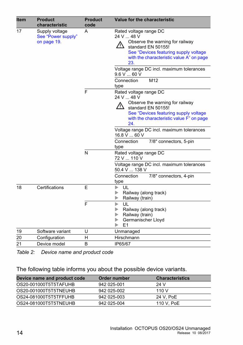
17 Supply voltageSee “Power supply” on page 19.
A Rated voltage range DC24 V ... 48 V
Observe the warning for railway standard EN 50155!See “Devices featuring supply voltage with the characteristic value A” on page 23.
Voltage range DC incl. maximum tolerances9.6 V ... 60 VConnection type
M12
F Rated voltage range DC24 V ... 48 V
Observe the warning for railway standard EN 50155!See “Devices featuring supply voltage with the characteristic value F” on page 24.
Voltage range DC incl. maximum tolerances16.8 V ... 60 VConnection type
7/8" connectors, 5-pin
N Rated voltage range DC72 V ... 110 VVoltage range DC incl. maximum tolerances50.4 V ... 138 VConnection type
7/8" connectors, 4-pin
18 Certifications E UL Railway (along track) Railway (train)
F UL Railway (along track) Railway (train) Germanischer Lloyd E1
19 Software variant U Unmanaged20 Configuration H Hirschmann21 Device model B IP65/67
Device name and product code Order number CharacteristicsOS20-001000T5T5TAFUHB 942 025-001 24 VOS20-001000T5T5TNEUHB 942 025-002 110 VOS24-081000T5T5TFFUHB 942 025-003 24 V, PoEOS24-081000T5T5TNEUHB 942 025-004 110 V, PoE
Item Product characteristic
Product code
Value for the characteristic
Table 2: Device name and product code
14Installation OCTOPUS OS20/OS24 Unmanaged
Release 10 08/2017

1.3 Device view
OS20-001000T5T5TAFUHB1 LED display elements Device Status
P1 Supply voltage 1P2 Supply voltage 2
2 100 Mbit/s ports3 Connecting the supply voltage4 Grounding screw M35 Product code6 LED display elements Port status
Power
N.C.
N.C.
P-
12345
P2+
Pin FunctionP1+
1
23
4
5Power
4 9
5 10
1
3
2
8
7
6
P1 P2
OS20-001000T5T5TAFUHB
x yOCTOPUS
OS20
UnmanagedETHERNET Switch
3
4
5
6
1 2
Installation OCTOPUS OS20/OS24 UnmanagedRelease 10 08/2017 15
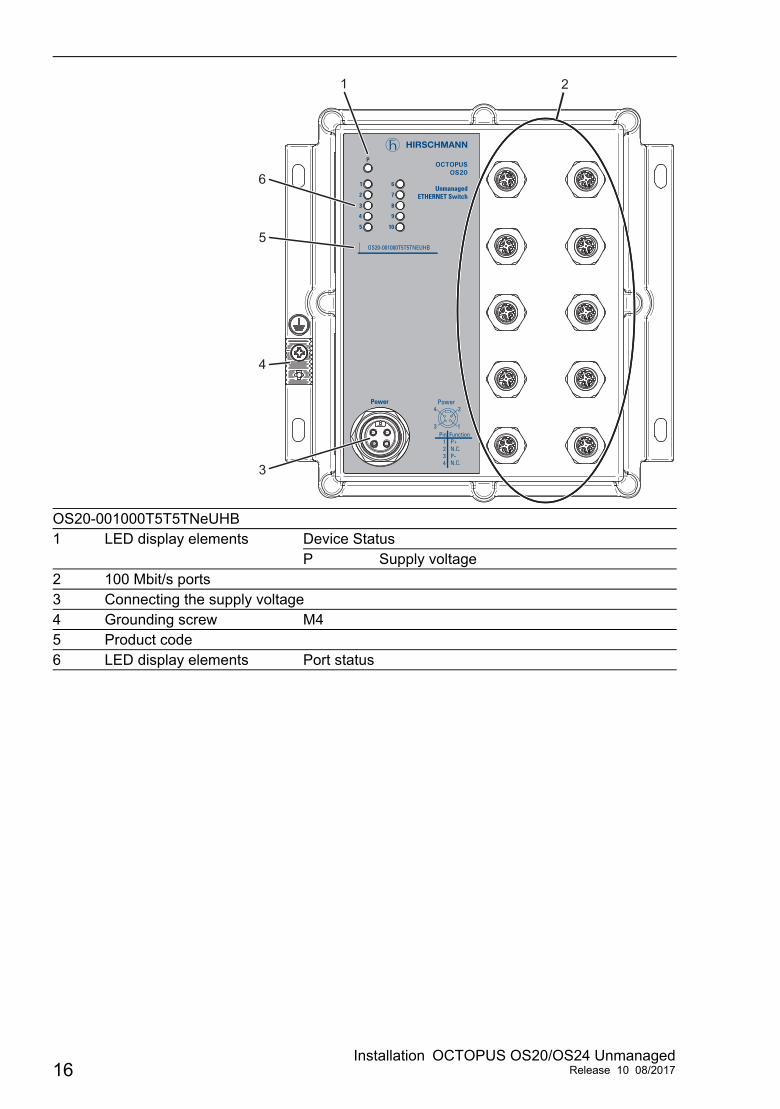
OS20-001000T5T5TNeUHB1 LED display elements Device Status
P Supply voltage2 100 Mbit/s ports3 Connecting the supply voltage4 Grounding screw M45 Product code6 LED display elements Port status
Power
N.C.P-
1234 N.C.
Pin FunctionP+
Power
1
24
3
P
4
5
1
3
2
9
10
8
7
6
x yOCTOPUS
OS20
UnmanagedETHERNET Switch
OS20-001000T5T5TNEUHB
3
4
5
6
1 2
16Installation OCTOPUS OS20/OS24 Unmanaged
Release 10 08/2017

OS24-081000T5T5TFFUHB1 LED display elements Device Status
P1 Supply voltage 1P2 Supply voltage 2FAULT Total PoE output
2 Ports1,6
100 Mbit/s ports
Ports2,3,4,5,7,8,9,10
100 Mbit/s PoE+ ports
3 Connecting the supply voltage4 Grounding screw M45 Product code6 LED display elements Port status
Power
N.C.
12345 P2+
Pin FunctionP1+
Power
4
51
23
P-
P1
4
5
1
3
2
9
10
8
7
6 PoE
PoE
P2 FAULT
x yOCTOPUS
OS24
UnmanagedETHERNET Switch
OS24-081000T5T5TFFUHB
P
Port 2-5, 7-10
3
4
5
6
1 2
Installation OCTOPUS OS20/OS24 UnmanagedRelease 10 08/2017 17

OS24-081000T5T5TNEUHB1 LED display elements Device Status
P Supply voltageFAULT Total PoE output
2 Ports1,6
100 Mbit/s ports
Ports2,3,4,5,7,8,9,10
100 Mbit/s PoE+ ports
3 Connecting the supply voltage4 Grounding screw M45 Product code6 LED display elements Port status
Power
N.C.P-
1234 N.C.
Pin FunctionP+
Power
1
24
3
4
5
1
3
2
9
10
8
7
6 PoE
PoE
FAULTP
x yOCTOPUS
OS24
UnmanagedETHERNET Switch
OS24-081000T5T5TNEUHB
P
Port 2-5, 7-10
3
4
5
6
1 2
18Installation OCTOPUS OS20/OS24 Unmanaged
Release 10 08/2017

1.4 Power supply
1.4.1 Supply voltage with the characteristic value AA 5-pin M12 plug is available for the redundant supply to the device.See “Devices featuring supply voltage with the characteristic value A” on page 23.
1.4.2 Supply voltage with the characteristic value FA 5-pin 7/8" connector is available to supply the device with PoE redundantly.See “Devices featuring supply voltage with the characteristic value F” on page 24.
1.4.3 Supply voltage with the characteristic value NA 4-pin 7/8" connector is available to supply the device.See “Devices featuring supply voltage with the characteristic value N” on page 25.
Installation OCTOPUS OS20/OS24 UnmanagedRelease 10 08/2017 19

1.5 Ethernet portsYou can connect end devices and other segments to the device ports using twisted pair cables or optical fibers (F/O).You find information on pin assignments for making patch cables here:“Pin assignments” on page 21
1.5.1 10/100 Mbit/s twisted pair portThis port is designed as an 4-pin M12 socket.The 10/100 Mbit/s twisted pair port allows you to connect network components according to the IEEE 802.3 10BASE-T/100BASE-TX standard.This port supports: Autonegotiation Autopolarity AutocrossingDelivery state: Autonegotiation activatedThe socket housing is electrically connected with the device housing.
Note: Some of these ports also support Power over Ethernet (PoE).See “10/100 Mbit/s PoE port” on page 20.
1.5.2 10/100 Mbit/s PoE portSome device variants support Power over Ethernet based on IEEE 802.3at (PoE+) via a twisted pair:
The PoE ports allow the connection and remote supply of, for example, IP telephones (Voice over IP), webcams, sensors, printer servers and WLAN access points. With PoE, power is supplied to these terminal devices via the twisted-pair cable.
Pin Function1 TD+ Transmission path2 RD+ Receive path3 TD− Transmission path4 RD− Receive pathHousing: shield
Table 3: Pin assignment of 10/100 Mbit/s twisted pair port, M12 socket
Device Number of TX ports PoE-capable TX ports included
OS20-... 10 NoneOS24-... 10 8
(Port 2 ... 5, 7 ... 10)
Table 4: Device types: Twisted-pair ports and PoE support
1
23
4
20Installation OCTOPUS OS20/OS24 Unmanaged
Release 10 08/2017

The devices are supplied with PoE voltage (53 V DC safety low voltage) via the internal voltage supply. The PoE voltage to the twisted-pair cables is supplied via the wire pairs transmitting the signal (phantom voltage).
The total PoE power output is limited to 61.6 W.
1.5.3 Pin assignments
M12 4-pin (“D”-coded) Pin Data PoE1 TX+ Positive VPSE2 RX+ Negative VPSE3 TX− Positive VPSE4 RX− Negative VPSE
M12 8-pin (“X”-coded) Pin 10/100 Mbit/s 1000 Mbit/s PoE1 RX+ BI_DB+ Negative VPSE2 RX− BI_DB− Negative VPSE3 TX+ BI_DA+ Positive VPSE4 TX− BI_DA− Positive VPSE5 — BI_DC+ —6 — BI_DC− —7 — BI_DD− —8 — BI_DD+ —
1
23
4
182
36
7
45
Installation OCTOPUS OS20/OS24 UnmanagedRelease 10 08/2017 21
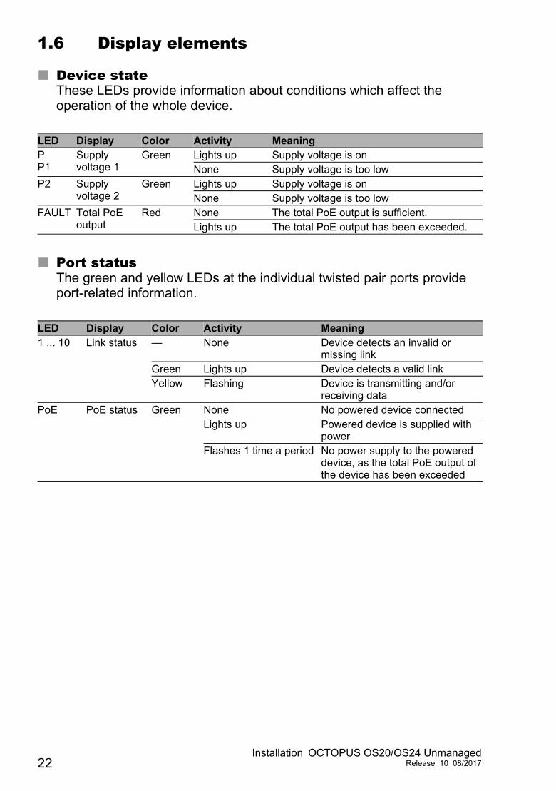
1.6 Display elements
Device stateThese LEDs provide information about conditions which affect the operation of the whole device.
Port statusThe green and yellow LEDs at the individual twisted pair ports provide port-related information.
LED Display Color Activity MeaningPP1
Supply voltage 1
Green Lights up Supply voltage is onNone Supply voltage is too low
P2 Supply voltage 2
Green Lights up Supply voltage is onNone Supply voltage is too low
FAULT Total PoE output
Red None The total PoE output is sufficient.Lights up The total PoE output has been exceeded.
LED Display Color Activity Meaning1 ... 10 Link status — None Device detects an invalid or
missing linkGreen Lights up Device detects a valid linkYellow Flashing Device is transmitting and/or
receiving dataPoE PoE status Green None No powered device connected
Lights up Powered device is supplied with power
Flashes 1 time a period No power supply to the powered device, as the total PoE output of the device has been exceeded
22Installation OCTOPUS OS20/OS24 Unmanaged
Release 10 08/2017

2 InstallationThe devices have been developed for practical application in a harsh industrial environment.On delivery, the device is ready for operation.
Perform the following steps to install and configure the device:
Checking the package contents Wiring the connector for the supply voltage Installing and grounding the device Connecting the ferrite Connecting the supply voltage Operating the device Connecting data cables
2.1 Checking the package contents Check whether the package includes all items named in the section
“Scope of delivery” on page 36. Check the individual parts for transport damage.
2.2 Wiring the connector for the supply voltage
Note: Only connect the device to a power supply that complies to surge voltage category II or lower.
2.2.1 Devices featuring supply voltage with the characteristic value A
WARNINGELECTRIC SHOCKThe nominal voltage of 48 V specified for trains can temporarily exceed the SELV threshold of 60 V based on EN 50155 para. 5.1.1.1. Use additional measures to limit the surge voltage to 60 V or use a lower nominal voltage. Failure to follow this instruction can result in death, serious injury, or equipment damage.
Installation OCTOPUS OS20/OS24 UnmanagedRelease 10 08/2017 23
The input voltage is electrically isolated from the housing. You have the option of supplying the supply voltage redundantly, without
load distribution. Use a power supply cable which is suitable for the voltage, the current and
the physical load.Hirschmann recommends a wire diameter of 0.5 mm² to 0.75 mm² (AWG20 to AWG18).
The supply voltage is connected via a 5-pin M12 connector (A coding, e.g. ELWIKA 5012 PG7 from Hirschmann, supplied).You find the prescribed tightening torque in General technical data section on page 32.
Connect the power supply cables.
2.2.2 Devices featuring supply voltage with the characteristic value F
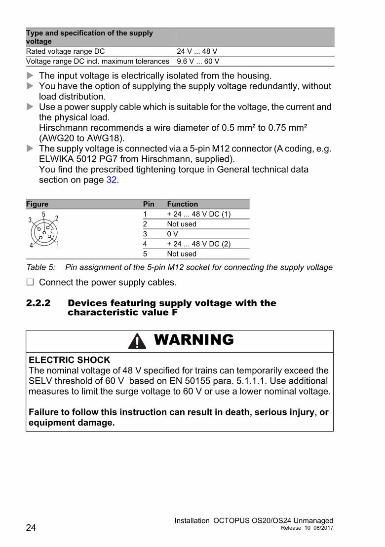
Type and specification of the supply voltage
Rated voltage range DC 24 V ... 48 VVoltage range DC incl. maximum tolerances 9.6 V ... 60 V
Figure Pin Function1 + 24 ... 48 V DC (1)2 Not used3 0 V4 + 24 ... 48 V DC (2)5 Not used
Table 5: Pin assignment of the 5-pin M12 socket for connecting the supply voltage
WARNINGELECTRIC SHOCKThe nominal voltage of 48 V specified for trains can temporarily exceed the SELV threshold of 60 V based on EN 50155 para. 5.1.1.1. Use additional measures to limit the surge voltage to 60 V or use a lower nominal voltage. Failure to follow this instruction can result in death, serious injury, or equipment damage.
24Installation OCTOPUS OS20/OS24 Unmanaged
Release 10 08/2017
The input voltage is electrically isolated from the housing. You have the option of supplying the supply voltage redundantly, without
load distribution. Use a power supply cable which is suitable for the voltage, the current and
the physical load.Hirschmann recommends a wire diameter of 0.75 mm² to 1.0 mm² (AWG18 to AWG16).
The supply voltage is connected via a 5-pin 7/8" connector.See “Accessories” on page 37.You find the prescribed tightening torque in General technical data section on page 32.
Connect the power supply cables.
2.2.3 Devices featuring supply voltage with the characteristic value N
The input voltage is electrically isolated from the housing. The supply voltage is connected via a 4-pin 7/8" connector.
See “Accessories” on page 37.You find the prescribed tightening torque in General technical data section on page 32.
Use a power supply cable which is suitable for the voltage, the current and the physical load.Hirschmann recommends a wire diameter of 0.75 mm² (AWG18).
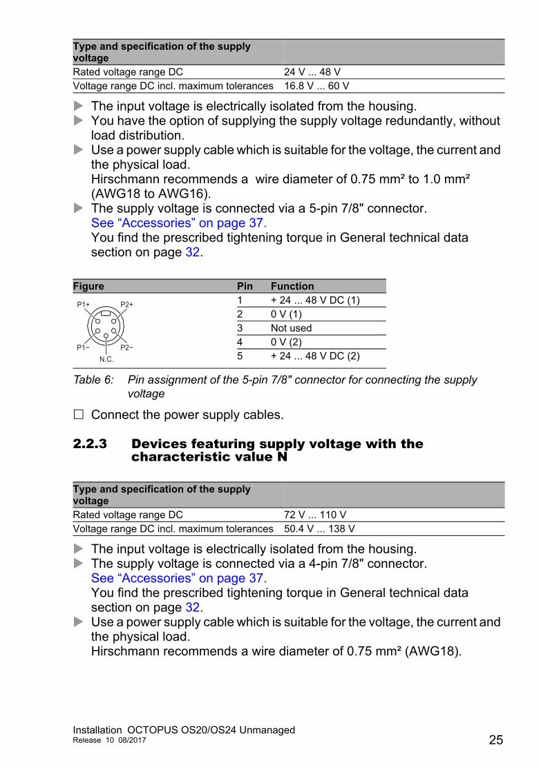
Type and specification of the supply voltage
Rated voltage range DC 24 V ... 48 VVoltage range DC incl. maximum tolerances 16.8 V ... 60 V
Figure Pin Function1 + 24 ... 48 V DC (1)2 0 V (1)3 Not used4 0 V (2)5 + 24 ... 48 V DC (2)
Table 6: Pin assignment of the 5-pin 7/8" connector for connecting the supply voltage
Type and specification of the supply voltage
Rated voltage range DC 72 V ... 110 VVoltage range DC incl. maximum tolerances 50.4 V ... 138 V
P2−
P2+P1+
P1−N.C.
Installation OCTOPUS OS20/OS24 UnmanagedRelease 10 08/2017 25

Connect the power supply cables.
2.3 Installing and grounding the device
Figure Pin Function1 + 72 ... 110 V DC2 Not used3 0 V4 Not used
Table 7: Pin assignment of the 4-pin 7/8" connector for connecting the supply voltage
WARNINGELECTRIC SHOCKApplies to devices featuring supply voltage with the characteristic value N:Install the device in such a way that it is protected against mechanical forces. Failure to follow this instruction can result in death, serious injury, or equipment damage.
WARNINGRISK OF BURNINGApplies to devices featuring supply voltage with the characteristic value N:Only install the device in “operating sites with restricted access” based on EN 60950-1. Applies to devices featuring supply voltage with the characteristic value A and F:At ambient temperatures > 49 °F (>45 °C):Install this device solely in a switch cabinet or in an operating site with restricted access, to which maintenance staff have exclusive access. Failure to follow this instruction can result in death, serious injury, or equipment damage.
P+
N.C.N.C.
P−
26Installation OCTOPUS OS20/OS24 Unmanaged
Release 10 08/2017

To protect the exposed uninstalled contacts of the components from dirt, connect the individual system components in a dry and clean working area.
When you are selecting the installation location, make sure you observe the climatic threshold values specified in the technical data.Prevent heat from the surroundings from affecting the device.
Applies to devices featuring supply voltage with the characteristic value F:Take care that the temperature of the device base plate remains under 194 °F (90 °C) during operation.You achieve this, for example, by means of one of the following measures: You make sure that the operating voltage of the device is at least 20 V. You limit the total PoE output to a maximum of 47 W. You limit the ambient temperature to a maximum of 149 °F (65 °C). You install the device on a 1.62 ft2 (0.15 m2) metal plate to which you
will connect no other heat sources. Prepare the drill holes at the installation point. Mount the device on a level surface with four M5 screws.
2.3.1 Grounding the deviceThe device is grounded via the separate ground screw.See “Device view” on page 15.The overall shield of a connected shielded twisted-pair cable is connected to the metal housing as a conductor. Applies to devices featuring supply voltage with the characteristic
value A:Use the M3 screw for the function ground.Applies to devices featuring supply voltage with characteristic value F and N:Use the M4 screw for the protective ground.
Use toothed washers to ensure good electrical conductivity at the connection.
Installation OCTOPUS OS20/OS24 UnmanagedRelease 10 08/2017 27

2.4 Connecting the ferriteApplies to devices featuring supply voltage with the characteristic value F:To adhere to EMC conformity, you connect the ferrite supplied to the voltage input via the power supply cable.
Insert the power supply cable through the ferrite 3 times. Position the ferrite as close as possible to the voltage input (max. distance
19.7 in (50 cm)). Lock the ferrite.
Note: To open the ferrite use the key supplied.
2.5 Connecting the supply voltage Use a back-up fuse suitable for the supply network.
See “General technical data” on page 32. Do not use connectors as electrical isolating devices. Make sure that the disconnecting device is easily accessible for
disconnecting the device from the mains voltage. Connect the power supply connector to the power supply socket of the
device.
28Installation OCTOPUS OS20/OS24 Unmanaged
Release 10 08/2017

2.6 Operating the deviceWhen you connect the supply voltage, you start up the device.
2.7 Connecting data cablesYou have the option to connect end devices or other segments to the ports of the device via twisted pair cables. Note the following general recommendations for data cable connections in environments with high electrical interference levels: Keep the length of the data cables as short as possible. Use optical data cables for the data transmission between the buildings. When using copper cables, provide a sufficient separation between the
power supply cables and the data cables. Ideally, install the cables in separate cable channels.
Verify that power supply cables and data cables do not run parallel over longer distances, and that ideally they are installed in separate cable channels. If reducing the inductive coupling is necessary, verify that the power supply cables and data cables cross at a 90° angle.
Use SF/UTP cables as per ISO/IEC 11801:2002. Use a shielded CAT5 cable or better. Use a shielded 4-pin M12 plug. Connect only PoE-supplier devices whose data connections are located
in the interior of the building and are specified as SELV circuits. There is no galvanic separation between the PoE ports of an OCTOPUS
OS24 device. If you are using these devices in ring structures, wire a PoE port with a non-PoE port to avoid a potential difference.
Proceed as follows: Connect the data cables according to your requirements.
The tightening torque is 5.3 lb-in (0.6 Nm). Seal all unused connections and ports with protection screws.
See “Accessories” on page 37.
Installation OCTOPUS OS20/OS24 UnmanagedRelease 10 08/2017 29

3 Monitoring the ambient air temperatureOperate the device below the specified maximum ambient air temperature exclusively.
The ambient air temperature is the temperature of the air at a distance of 2 in (5 cm) from the device. It depends on the installation conditions of the device, e.g. the distance from other devices or other objects, and the output of neighboring devices.
The temperature displayed in the CLI and the GUI is the internal temperature of the device. It is higher than the ambient air temperature. The maximum internal temperature of the device named in the technical data is a guideline that indicates to you that the maximum ambient air temperature has possibly been exceeded.
Therefore, the temperature value displayed in the CLI and the GUI differs from the ambient air temperature.
To determine the actual permitted maximum value for operating the device, you perform a reference measurement: Install the device at the planned location. Switch the device on and wait until it has reached its maximum operating
temperature. Measure the ambient air temperature at a distance of 2 in (5 cm) from the
device. Read the temperature value displayed in the CLI or the GUI. Calculate the temperature difference. Add the difference to the maximum ambient air temperature specified in
the manual.
This calculated value corresponds to the actual maximum permitted ambient air temperature, up to which you can operate the device.
30Installation OCTOPUS OS20/OS24 Unmanaged
Release 10 08/2017

4 Maintenance and serviceWhen designing this device, Hirschmann largely avoided using high-wear parts. The parts subject to wear and tear are dimensioned to last longer than the lifetime of the product when it is operated normally. Operate this device according to the specifications.Relays are subject to natural wear. This wear depends on the frequency of the switching operations. Check the resistance of the closed relay contacts and the switching function depending on the frequency of the switching operations.Hirschmann is continually working on improving and developing their software. Check regularly whether there is an updated version of the software that provides you with additional benefits. You find information and software downloads on the Hirschmann product pages on the Internet (www.hirschmann.com).
Note: You find information on settling complaints on the Internet at http://www.beldensolutions.com/en/Service/Reparaturen/index.phtml.
Installation OCTOPUS OS20/OS24 UnmanagedRelease 10 08/2017 31

5 Technical data
General technical data
Dimensions W × H × D
See “Dimension drawings” on page 34.
Weight 67.02 oz (1900 g)Power supplyType A
Redundant power supplyNote: Ensure that the externally power unit connected upstream fulfills one of following conditions: NEC Class 2 Limited Power Source based on EN 60950-1
Rated voltage range DC 24 V ... 48 VObserve the warning for railway standard EN 50155!See “Devices featuring supply voltage with the characteristic value A” on page 23.
Voltage range DC incl. maximum tolerances
9.6 V ... 60 V
Connection type M12 connector, 5 pinTightening torque 5.3 lb-in
(0.6 Nm)Power loss buffer > 10 msOverload current protection at input Non-replaceable fuseBack-up fuse Nominal rating:
Characteristic:2 Aslow blow
Peak inrush current 14 APower supplyType F
Redundant power supplyRated voltage range DC 24 V ... 48 V
Observe the warning for railway standard EN 50155!See “Devices featuring supply voltage with the characteristic value F” on page 24.
Voltage range DC incl. maximum tolerances
16.8 V ... 60 V
Connection type 7/8" connectors, 5-pinTightening torque 22 lb-in
(2.5 Nm)Power loss buffer > 10 ms
No buffering of powered devices (PDs)
Overload current protection at input Non-replaceable fuseBack-up fuse Nominal rating:
Characteristic:7 Aslow blow
Peak inrush current 4.9 A
32Installation OCTOPUS OS20/OS24 Unmanaged
Release 10 08/2017
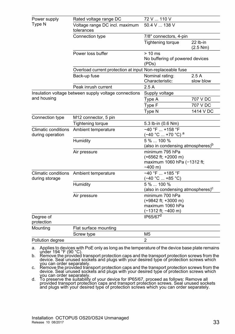
Power supplyType N
Rated voltage range DC 72 V ... 110 VVoltage range DC incl. maximum tolerances
50.4 V ... 138 V
Connection type 7/8" connectors, 4-pinTightening torque 22 lb-in
(2.5 Nm)Power loss buffer > 10 ms
No buffering of powered devices (PDs)
Overload current protection at input Non-replaceable fuseBack-up fuse Nominal rating:
Characteristic:2.5 Aslow blow
Peak inrush current 2.5 AInsulation voltage between supply voltage connections and housing
Supply voltageType A 707 V DCType F 707 V DCType N 1414 V DC
Connection type M12 connector, 5 pinTightening torque 5.3 lb-in (0.6 Nm)
Climatic conditions during operation
Ambient temperature −40 °F ... +158 °F (−40 °C ... +70 °C) a
Humidity 5 % ... 100 %(also in condensing atmospheres)b
Air pressure minimum 795 hPa (+6562 ft; +2000 m)maximum 1060 hPa (−1312 ft; −400 m)
Climatic conditions during storage
Ambient temperature −40 °F ... +185 °F (−40 °C ... +85 °C)
Humidity 5 % ... 100 %(also in condensing atmospheres)c
Air pressure minimum 700 hPa (+9842 ft; +3000 m)maximum 1060 hPa (−1312 ft; −400 m)
Degree of protection
IP65/67d
Mounting Flat surface mountingScrew type M5
Pollution degree 2
a. Applies to devices with PoE only as long as the temperature of the device base plate remains under 194 °F (90 °C).
b. Remove the provided transport protection caps and the transport protection screws from the device. Seal unused sockets and plugs with your desired type of protection screws which you can order separately.
c. Remove the provided transport protection caps and the transport protection screws from the device. Seal unused sockets and plugs with your desired type of protection screws which you can order separately.
d. To preserve the suitability of your device for IP65/67, proceed as follows: Remove all provided transport protection caps and transport protection screws. Seal unused sockets and plugs with your desired type of protection screws which you can order separately.
Installation OCTOPUS OS20/OS24 UnmanagedRelease 10 08/2017 33

Dimension drawings
Figure 1: Dimensions
EMC and immunity
EMC interference immunityIEC/EN 61000-4-2 Electrostatic discharge
Contact dischargeAir discharge
6 kV8 kV
IEC/EN 61000-4-3 Electromagnetic field80 MHz ... 2700 MHz
20 V/m
IEC/EN 61000-4-4 Fast transients (burst)AC/DC supply connectionData line
2 kV4 kV
IEC/EN 61000-4-5 Voltage surgesDC supply connection Data line
line/lineline/ground
1 kV2 kV1 kV
IEC/EN 61000-4-6 Conducted disturbances150 kHz ... 80 MHz
10 V
EN 61000-4-9 Pulse magnetic fields 300 A/m
EMC interference emissionEN 55032 Class A YesFCC 47 CFR Part 15 Class A Yes
52,8
mm
2.08
inch
171,8 mm6.77 inch
183,8 mm7.24 inch
188,
5 m
m7.
43 in
ch
120
mm
4.73
inch
34Installation OCTOPUS OS20/OS24 Unmanaged
Release 10 08/2017

Network range
German Lloyd Classification + Construction Guidelines VI-7-3 Part 1 Ed.2001
Yes
StabilityVibration IEC 60068-2-6 Test FC test level according to IEC 61131-2 Yes
Germanischer Lloyd Guidelines for the Performance of Type Tests Part 1
Yes
IEC 60870-2-2 table 3 normal installation according to EN 61850-3
Yes
EN 61373, Category 1, Class A (broadband noise), installation in acc. with EN 50155
Yes
Shock IEC 60068-2-27 Test Ea test level according to IEC 61131-2 YesIEC 60870-2-2 table 3 normal installation according to EN 61850-3
Yes
EN 61373, Category 1, Class A (broadband noise), installation in acc. with EN 50155
Yes
10/100/1000 Mbit/s twisted pair portLength of a twisted pair segment max. 328 ft (100 m) (for Cat5e cable)
EMC interference emission
Installation OCTOPUS OS20/OS24 UnmanagedRelease 10 08/2017 35

Power consumption/power output
Scope of delivery
Order numbers/product description
Device name and product code
Maximum power consumption Power output
OS20-001000T5T5TAFUHB 5.8 W 19.8 Btu (IT)/hOS20-001000T5T5TNEUHB 12 W 41 Btu (IT)/hOS24-081000T5T5TFFUHB 80 W 68 Btu (IT)/hOS24-081000T5T5TNEUHB 80 W 68 Btu (IT)/h
Device name and product code Scope of deliveryOS20-001000T5T5TAFUHB OCTOPUS device
Connector ELWIKA 5012 PG7 for supply voltage
Note: The connector ELWIKA 5012 PG7 (933 175-100) supports a temperature range from −13 °F to +158 °F (−25 °C to +70 °C). It may thus limit the application range of the overall system.Special connectors with protection classes IP65/67 and an extended temperature range are available on request.
General safety instructionsOS24-081000T5T5TFFUHB OCTOPUS device
Ferrite with keyGeneral safety instructions
OS20-001000T5T5TNEUHBOS24-081000T5T5TNEUHB
OCTOPUS deviceGeneral safety instructions
Device name and product code Order numberOS20-001000T5T5TAFUHB 942 025-001OS20-001000T5T5TNEUHB 942 025-002OS24-081000T5T5TFFUHB 942 025-003OS24-081000T5T5TNEUHB 942 025-004
Table 8: Device types: product code, order number
36Installation OCTOPUS OS20/OS24 Unmanaged
Release 10 08/2017
Accessories
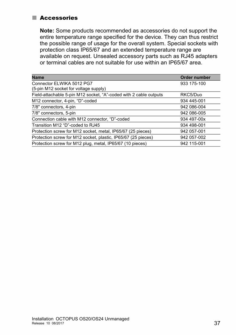
Note: Some products recommended as accessories do not support the entire temperature range specified for the device. They can thus restrict the possible range of usage for the overall system. Special sockets with protection class IP65/67 and an extended temperature range are available on request. Unsealed accessory parts such as RJ45 adapters or terminal cables are not suitable for use within an IP65/67 area.
Name Order numberConnector ELWIKA 5012 PG7 (5-pin M12 socket for voltage supply)
933 175-100
Field-attachable 5-pin M12 socket, “A”-coded with 2 cable outputs RKC5/DuoM12 connector, 4-pin, “D”-coded 934 445-0017/8" connectors, 4-pin 942 086-0047/8" connectors, 5-pin 942 086-005Connection cable with M12 connector, “D”-coded 934 497-00xTransition M12 “D”-coded to RJ45 934 498-001Protection screw for M12 socket, metal, IP65/67 (25 pieces) 942 057-001Protection screw for M12 socket, plastic, IP65/67 (25 pieces) 942 057-002Protection screw for M12 plug, metal, IP65/67 (10 pieces) 942 115-001
Installation OCTOPUS OS20/OS24 UnmanagedRelease 10 08/2017 37

Underlying technical standards
The device has an approval based on a specific standard only if the approval indicator appears on the device casing.If your device has a shipping approval according to Germanischer Lloyd, you find the approval mark printed on the device label. You will find out whether your device has other shipping approvals on the Hirschmann website under www.hirschmann.com in the product information.
NameEN 50121-4 Railway applications - EMC - emitted interference and
interference immunity for signal and telecommunication systems
EN 50155 Railway applications - Electronic equipment used on rolling stock
EN 55032 Electromagnetic compatibility of multimedia equipment – Emission Requirements
EN 61000-6-2 Electromagnetic compatibility (EMC) – Part 6-2: Generic standards – Immunity for industrial environments
EN 61131-2 Programmable controllers – Part 2: Equipment requirements and tests
FCC 47 CFR Part 15 Code of Federal RegulationsGermanischer Lloyd Rules for Classification and Construction VI-7-2 – GL72/245/EWG, 2009/19/EG E type certification for use in vehiclesDIN 5510-2,NF F 16-101, NF F 16-102
Fire protection in railway vehicles
UL 60950-1 Information technology equipment – Safety – Part 1: General requirements
Table 9: List of the technical standards
38Installation OCTOPUS OS20/OS24 Unmanaged
Release 10 08/2017

A Further support
Technical questions
For technical questions, please contact any Hirschmann dealer in your area or Hirschmann directly.
You find the addresses of our partners on the Internet at http://www.hirschmann.com.
A list of local telephone numbers and email addresses for technical support directly from Hirschmann is available at https://hirschmann-support.belden.eu.com.
This site also includes a free of charge knowledge base and a software download section.
Hirschmann Competence Center
The Hirschmann Competence Center is ahead of its competitors on three counts with its complete range of innovative services:
Consulting incorporates comprehensive technical advice, from system evaluation through network planning to project planning.
Training offers you an introduction to the basics, product briefing and user training with certification.You find the training courses on technology and products currently available at http://www.hicomcenter.com.
Support ranges from the first installation through the standby service to maintenance concepts.
With the Hirschmann Competence Center, you decided against making any compromises. Our client-customized package leaves you free to choose the service components you want to use.
Internet:http://www.hicomcenter.com
Installation OCTOPUS OS20/OS24 UnmanagedRelease 10 08/2017 39