
Installation manual turbokit - MC Xpress i Altersbruk · Install the pressure hose between the...
24
1 Installation manual turbo kit 190 hp Yamaha Viper / Arctic Cat 7000 MC Xpress AB Norra Altervägen 821 945 92 ALTERSBRUK Sweden Tel: +46 911 202005 Fax: +46 911 202008 www.mcx.se
Transcript of Installation manual turbokit - MC Xpress i Altersbruk · Install the pressure hose between the...

1
Installation manual turbo kit
190 hp Yamaha Viper
/ Arctic Cat 7000
MC Xpress AB
Norra Altervägen 821
945 92 ALTERSBRUK
Sweden
Tel: +46 911 202005
Fax: +46 911 202008
www.mcx.se

2
Supreme of the extreme !
Viper / AC 7000 turbo 190 hp
Thank you for choosing the MC Xpress turbo kit to your Yamaha Viper / Arctic Cat 7000
snowmobile.
The turbo kit is designed for racing use only.
The turbo kit is designed to give you the best performance possible together with reliability.
During the developement work we have tried to keep the snowmobile as stock as possible to
make the installation easy and to keep the sled as untouched as possible.
Read this manual carefully before you start with the installation.
We hope you will get much joy with your new investment.
The turbo snowmobile is only recommended to be used by experienced riders and for racing
use only.
This turbo kit greatly enhances the performance of the vehicle it is installed upon!
Professional training should be received by anyone that operates this modified vehicle.
Installation of this turbo kit may void any warranty that is provided by the vehicle
manufacturer.
A one (1) year warranty is provided on the kit parts only. This warranty does not cover
any other parts even if the damage is caused by the installation of the turbo kit.
MCXpress AB, its distributors, dealers, nor installers will not be held liable for any
personal or physical damaged obtained in association with the installation or use of this
product.
By installation or purchase of this product, the end user and or installer agree that the end user
has been informed of this information.
AC 7000 / Viper 190 hp turbo kit. Changes may have been done since the picture was taken.
3
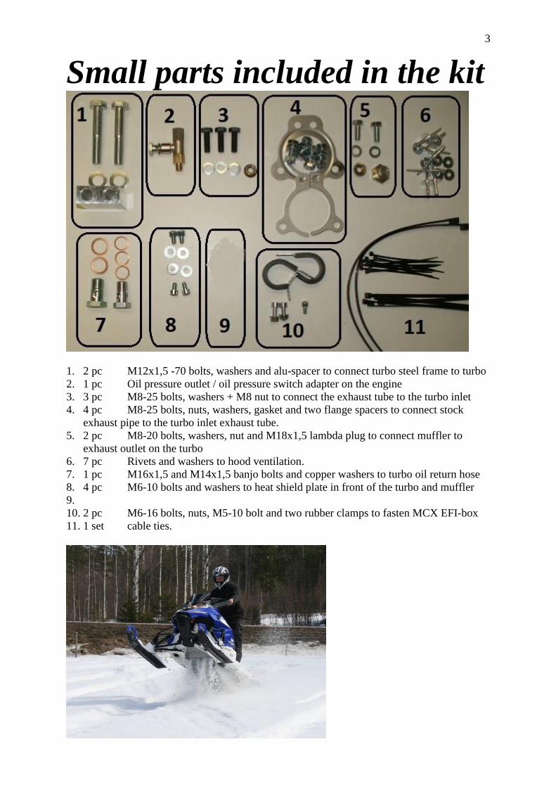
Small parts included in the kit
1. 2 pc M12x1,5 -70 bolts, washers and alu-spacer to connect turbo steel frame to turbo
2. 1 pc Oil pressure outlet / oil pressure switch adapter on the engine
3. 3 pc M8-25 bolts, washers + M8 nut to connect the exhaust tube to the turbo inlet
4. 4 pc M8-25 bolts, nuts, washers, gasket and two flange spacers to connect stock
exhaust pipe to the turbo inlet exhaust tube.
5. 2 pc M8-20 bolts, washers, nut and M18x1,5 lambda plug to connect muffler to
exhaust outlet on the turbo
6. 7 pc Rivets and washers to hood ventilation.
7. 1 pc M16x1,5 and M14x1,5 banjo bolts and copper washers to turbo oil return hose
8. 4 pc M6-10 bolts and washers to heat shield plate in front of the turbo and muffler
9.
10. 2 pc M6-16 bolts, nuts, M5-10 bolt and two rubber clamps to fasten MCX EFI-box
11. 1 set cable ties.

4
Before the installation
Very important to know:
This turbo kit is designed for 190 hp and 143 kPa (=21 psi) absolute pressure.
(This is 43 kPa (6 psi) turbo pressure at sea level)
If higher pressure is used, the risk of engine damages will rise rapidly.
Premium fuel or higher octane shall be used (98 octane pump gas for Europe)
To make the installation as efficient as possible, we recommend you to follow these
instructions.
To begin with, we recommend to:
Remove the plastic side covers and the headlight/hood.
Remove the muffler and the air box.
Oil hose to turbo The oil hose to the turbo shall be installed on the rear side of the engine where the oil pressure
switch is located. Remove the cover under the engine.
To make it easier, you can lift up one side of the sled, so you easier can work from under.
Remove the oil pressure cover from the engine by removing two M6 bolts.
Remove the oil pressure sensor from the cover.
Cut one ear on the oil pressure cover.
Install the adapter supplied wit the kit where the oil pressure sensor was located.
Use Loc-tite thread sealant (or similar) on the threads of the gold coloured nipple.
Install the sensor to the special banjo bolt.
Use thread sealant on the sensor threads. (But not to much)
Install the oil hose to the turbo (=the hose with 10 mm banjo on one side and 12 mm banjo on
the other) the T-fitting like the picture..
Use cupper washers between each item.

5
Vacuum hose to throttle body
Install the vacuum hoses to the throttle body.

6
Air temp sensor
The air temp sensor shall be removed from the stock air box.
Connect the sensor to the stock wire harness and strap it towards the stock wire harness like
the picture.

7
EFI-box installation
Install the MCX- EFI-box to left side of the frame with two rubber clamps like the picture.
Disconnect the big connector se picture above, and install the EFI-box 16 pin connectors here.
Connect the black EFI-box ground cable to the chassis.
The two pin connector shall go the the TCV valve on the turbo.
The 10 pin connector is made for options.
The MCX display or the MCX blue tooth module can be installed to this connector.
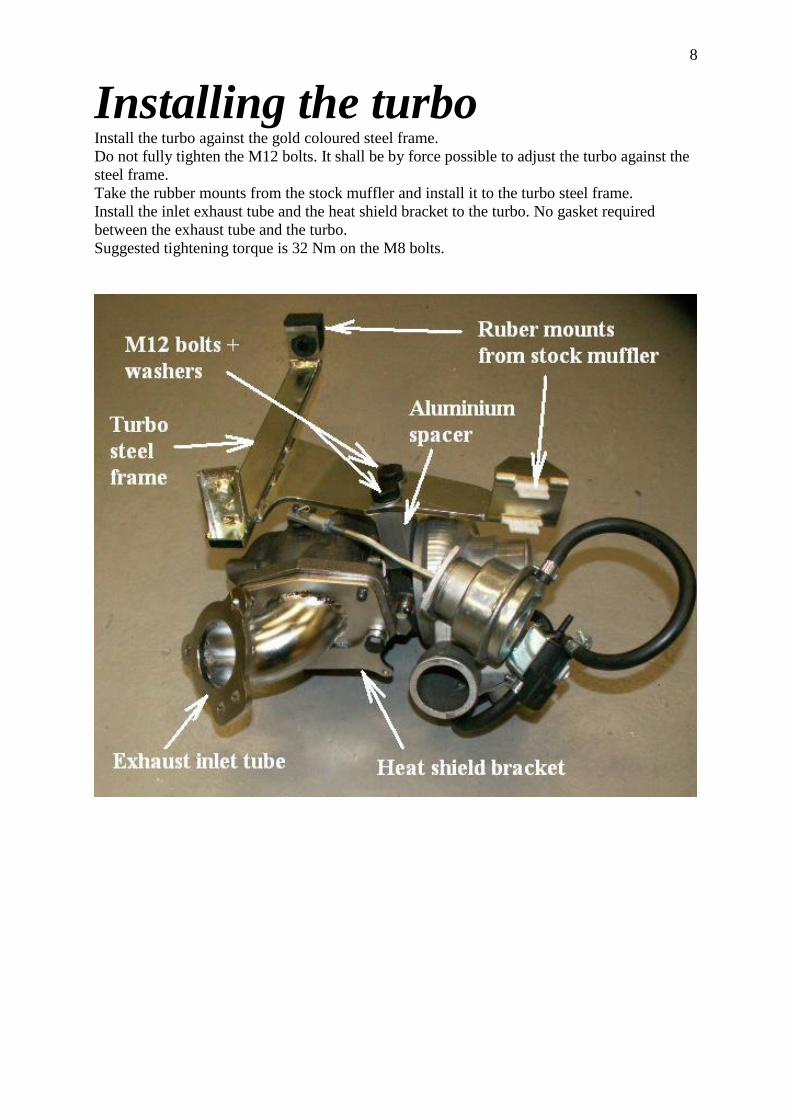
8
Installing the turbo Install the turbo against the gold coloured steel frame.
Do not fully tighten the M12 bolts. It shall be by force possible to adjust the turbo against the
steel frame.
Take the rubber mounts from the stock muffler and install it to the turbo steel frame.
Install the inlet exhaust tube and the heat shield bracket to the turbo. No gasket required
between the exhaust tube and the turbo.
Suggested tightening torque is 32 Nm on the M8 bolts.

9
Install the turbo to the chassis.
Install temporary the muffler to the exhaust outlet of the turbo.
Turn the turbo against the steel frame until the exhaust outlet of the muffler is in the middle of
the exhaust outlet of the chassis.
Remove the turbo from the chassis and final tighten the M12 bolts. Suggested torque is 60
Nm.
Install the turbo again in the chassis.
Install the oil return hose from the turbo to the generator cover like the picture.
Use two copper washers between the banjo fitting and the generator cover.
This is to prevent the hose from touching the generator cover.

10
We recommend to remove the heat protector from the right plastic fairing.
Install it between the engine and the muffler to prevent the engine from the muffler heat.
Use cable ties. Make a hole for the oil return hose.
Install the oil inlet hose to the turbo. But before you install this hose on top of the turbo,
lubricate the oil inlet of the turbo with fresh motor oil so it will be lubricated at once when
you crank the engine.
Install the exhaust tube going into the turbo against the stock exhaust system.
Use the new stainless steel gasket supplied with the kit.
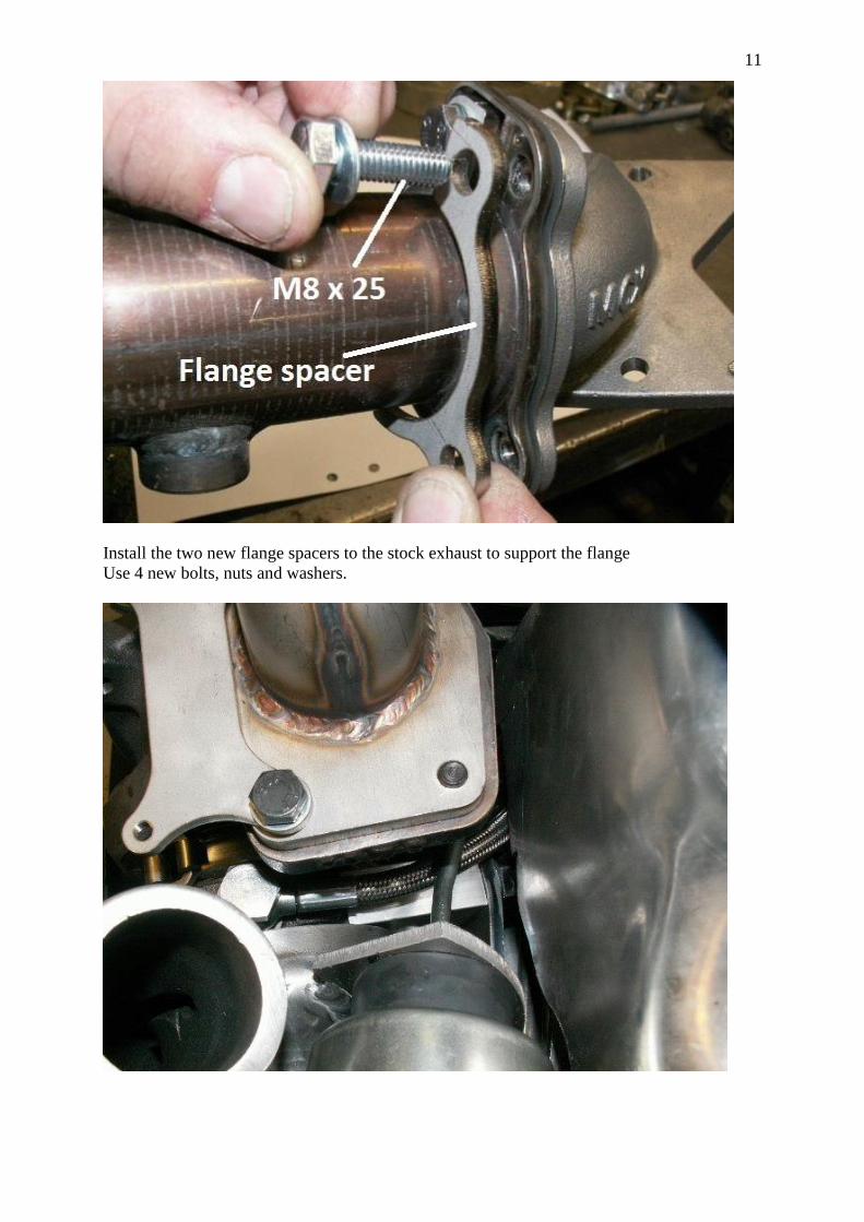
11
Install the two new flange spacers to the stock exhaust to support the flange
Use 4 new bolts, nuts and washers.
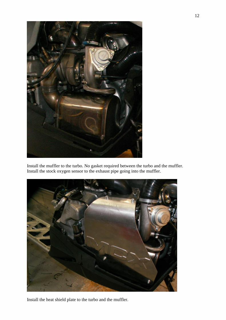
12
Install the muffler to the turbo. No gasket required between the turbo and the muffler.
Install the stock oxygen sensor to the exhaust pipe going into the muffler.
Install the heat shield plate to the turbo and the muffler.

13
Install the air inlet hose to the turbo including the rubber ring on the hose to centre the air
filter, and the snow air filter.
Also install the new engine vent tube between the catch tank and the turbo air inlet hose.
Connect the small hose coming from the valve cover to the engine ventilation tube.
And finally connect the vacuum hose from the throttle body to the blow off valve on the
turbo.
14
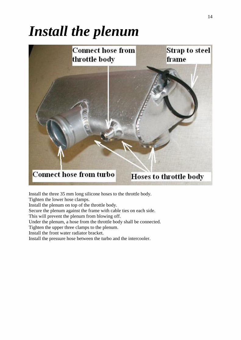
Install the plenum
Install the three 35 mm long silicone hoses to the throttle body.
Tighten the lower hose clamps.
Install the plenum on top of the throttle body.
Secure the plenum against the frame with cable ties on each side.
This will prevent the plenum from blowing off.
Under the plenum, a hose from the throttle body shall be connected.
Tighten the upper three clamps to the plenum.
Install the front water radiator bracket.
Install the pressure hose between the turbo and the intercooler.

15
The stock baro pressure sensor that is located on the throttle body shall be pressurized from
the plenum. This prevents the engine from running lean at high altitude.
A small nipple shall be installed on the plenum (see picture).
Install a hose between the nipple and the stock baro pressure sensor.
(picture is from the Viper 270 plenum)

16
Start the engine
Check water level in the cooling system.
Check oil level.
Start the engine before you put on the fairings.
Check for leaks.
Caution: We recommend loosening the oil inlet M12 banjo-screw on the turbo for a second
just after you started the engine, just to make sure the engine and turbo get lubricated.
If everything seems to be working fine, install the heat shield. Let the engine be heated up and
make sure the water is circulating through the radiator.
Install the remaining parts.
Test-driving OBS: The clutch has to be modified to handle the extra power. See more info under
“options”.
CAUTION: Always use high octane pump gas or race gas. Low octane may cause engine
damages. Test-drive the snowmobile.
CAUTION: Be very careful when you drive in the beginning.
Check water level and oil level once again after the engine has been running
Check for leaks and control so everything seems normal. It is very important that it is no air
left in the water cooling system.
The recommended turbo pressure is 43 kPa. (6psi) at sea level The maximum power will then
be 190 hp.
Using higher turbo pressure may cause engine damages.
If higher performance is requested, we recommend low compression pistons or that you use
race gas. The air/fuel ratio shall also be recorded to avoid the engine from running lean.
IMPORTANT:
The maximum turbo pressure must be tested.
When testing turbo pressure, we recommend connecting a gauge via a T-connector on the
same hose as to the blow off valve/MCX EFI box .
The test shall be made at full throttle for at least 2-3 seconds. And the clutching must be right
when doing this.
We recommend being careful when doing this.
17
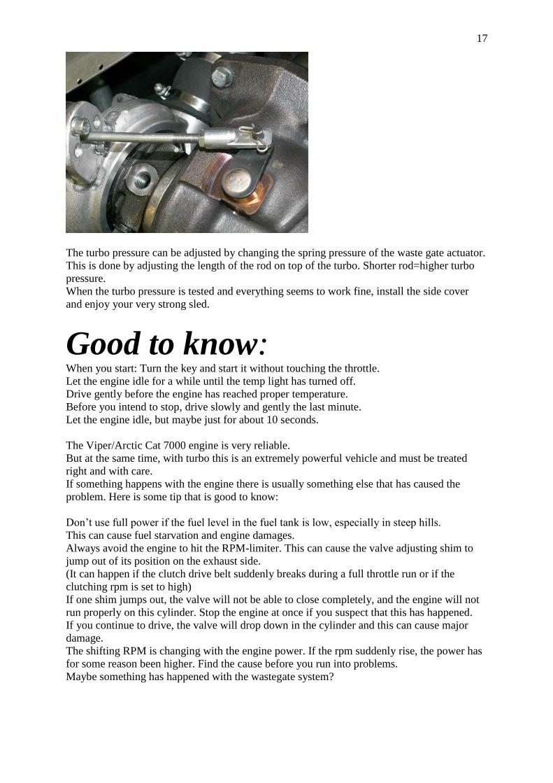
The turbo pressure can be adjusted by changing the spring pressure of the waste gate actuator.
This is done by adjusting the length of the rod on top of the turbo. Shorter rod=higher turbo
pressure.
When the turbo pressure is tested and everything seems to work fine, install the side cover
and enjoy your very strong sled.
Good to know: When you start: Turn the key and start it without touching the throttle.
Let the engine idle for a while until the temp light has turned off.
Drive gently before the engine has reached proper temperature.
Before you intend to stop, drive slowly and gently the last minute.
Let the engine idle, but maybe just for about 10 seconds.
The Viper/Arctic Cat 7000 engine is very reliable.
But at the same time, with turbo this is an extremely powerful vehicle and must be treated
right and with care.
If something happens with the engine there is usually something else that has caused the
problem. Here is some tip that is good to know:
Don’t use full power if the fuel level in the fuel tank is low, especially in steep hills.
This can cause fuel starvation and engine damages.
Always avoid the engine to hit the RPM-limiter. This can cause the valve adjusting shim to
jump out of its position on the exhaust side.
(It can happen if the clutch drive belt suddenly breaks during a full throttle run or if the
clutching rpm is set to high)
If one shim jumps out, the valve will not be able to close completely, and the engine will not
run properly on this cylinder. Stop the engine at once if you suspect that this has happened.
If you continue to drive, the valve will drop down in the cylinder and this can cause major
damage.
The shifting RPM is changing with the engine power. If the rpm suddenly rise, the power has
for some reason been higher. Find the cause before you run into problems.
Maybe something has happened with the wastegate system?

18
Dyno graph Yamaha Viper/Arctic Cat 7000 turbo, 190 hp turbo kit.
Fairing modification Note: Only on Arctic Cat 7000 model
Cut the edge of the right side fairing like the dotted line.

19
Stickers Yamaha:
Install the stickers like the pictures.
Put the sticker ”98 octane” (Europe) or ”Premium only” (USA/Canada) close to the fuel cap
as a reminder of the recommende fuel quality.
Install air ventilation net on the right side cover above the turbo and the muffler.
First mark where to cut, then cut up the hole.
Place the air net on top of the plastic cover and drill holes for the rivets.
Place a washer on the inner side when installing the rivets.

20
Options:
Display and log unit.
This display can show pressure, lambda or air fuel ratio, rpm, baro pressure, etc.
It can also sample data 10 times each second.
This info, you can be downloaded via the USB cable to your PC.
The MCX EFI-box is prepared with a connector, so it is just “plug and play”
A Bosch wide range oxygen sensor is included.
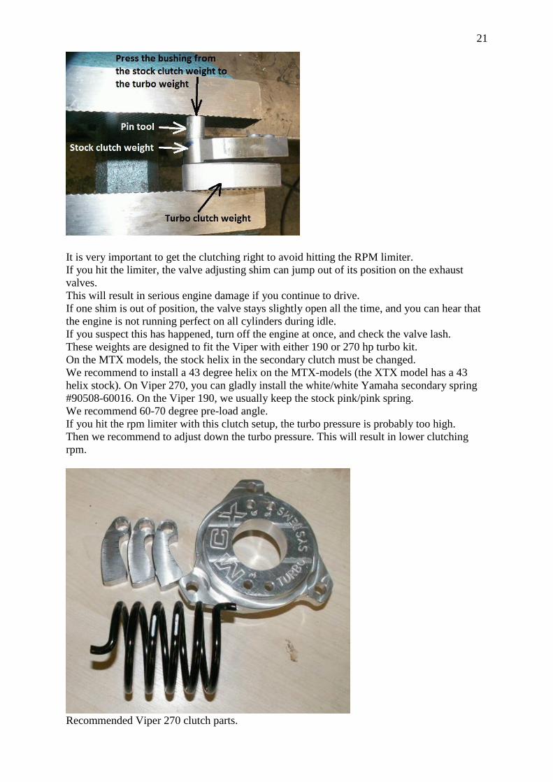
Clutch Kit for Yamaha Viper 190 / 270 turbo Use the stock bushings when installing the turbo clutch weights.
Press over the bushing to the turbo weight by using the pin-tool supplied with the clutch kit.
Be careful so you don’t destroy the bushing during the operation.
(see next page)
21
It is very important to get the clutching right to avoid hitting the RPM limiter.
If you hit the limiter, the valve adjusting shim can jump out of its position on the exhaust
valves.
This will result in serious engine damage if you continue to drive.
If one shim is out of position, the valve stays slightly open all the time, and you can hear that
the engine is not running perfect on all cylinders during idle.
If you suspect this has happened, turn off the engine at once, and check the valve lash.
These weights are designed to fit the Viper with either 190 or 270 hp turbo kit.
On the MTX models, the stock helix in the secondary clutch must be changed.
We recommend to install a 43 degree helix on the MTX-models (the XTX model has a 43
helix stock). On Viper 270, you can gladly install the white/white Yamaha secondary spring
#90508-60016. On the Viper 190, we usually keep the stock pink/pink spring.
We recommend 60-70 degree pre-load angle.
If you hit the rpm limiter with this clutch setup, the turbo pressure is probably too high.
Then we recommend to adjust down the turbo pressure. This will result in lower clutching
rpm.
Recommended Viper 270 clutch parts.

22
Option: Snorkel air intake kit for
Yamaha Viper / Arctic Cat 7000
For deep snow riding
Drill a hole diameter about 65 mm like the picture.
Grind up the hole until the hose fits fine.

23
Remove the air inlet hose to the turbo and the air filer aluminum basket.
Cut the air inlet hose like the picture.
Cut the engine vent hose also. Remove the straight end (in the left of the picture) of the tube,
but keep it if you want to put the filter under the hood again in the future.
This is how the snorkel kit shall be installed
(The upper fairing is taken off just to show how it looks like)

24


![[XLS] · Web view163 (Chowdury Bari), Janata Housing Road, Baro Bagh, Mirpur 152 (Nazrul), Janata Housing Road, Baro Bagh, Mirpur 86 (Dr. Deloara House), Janata housing Road, Baro](https://static.fdocuments.in/doc/165x107/5ab19ae47f8b9abc2f8cf86a/xls-view163-chowdury-bari-janata-housing-road-baro-bagh-mirpur-152-nazrul.jpg)