Installation manual - SUNNY ISLAND 3.0M / 4.4M / 6.0H / 8€¦ · Installation manual SUNNY ISLAND...
112
SI30M-44M-60H-80H-IA-en-32 | Version 3.2 ENGLISH Installation manual SUNNY ISLAND 3.0M / 4.4M / 6.0H / 8.0H
Transcript of Installation manual - SUNNY ISLAND 3.0M / 4.4M / 6.0H / 8€¦ · Installation manual SUNNY ISLAND...

SI30M-44M-60H-80H-IA-en-32 | Version 3.2 ENGLISH
Installation manualSUNNY ISLAND 3.0M / 4.4M / 6.0H / 8.0H

Legal Provisions SMA Solar Technology AG
2 SI30M-44M-60H-80H-IA-en-32 Installation manual
Legal ProvisionsThe information contained in this document is the property of SMA Solar Technology AG. Publishing its content, either partially or in full, requires the written permission of SMA Solar Technology AG. Any internal company copying of the document for the purposes of evaluating the product or its correct implementation is allowed and does not require permission.
SMA WarrantyYou can download the current warranty conditions from the Internet at www.SMA-Solar.com.
TrademarksAll trademarks are recognized, even if not explicitly identified as such. A lack of identification does not mean that a product or symbol is not trademarked.The BLUETOOTH® word mark and logos are registered trademarks owned by Bluetooth SIG, Inc. and any use of these marks by SMA Solar Technology AG is under license.Modbus® is a registered trademark of Schneider Electric and is licensed by the Modbus Organization, Inc.QR Code is a registered trademark of DENSO WAVE INCORPORATED.Phillips® and Pozidriv® are registered trademarks of Phillips Screw Company.Torx® is a registered trademark of Acument Global Technologies, Inc.
SMA Solar Technology AG Sonnenallee 1 34266 Niestetal GermanyTel. +49 561 9522-0 Fax +49 561 9522-100 www.SMA.de E-mail: [email protected]© 2004 to 2015 SMA Solar Technology AG. All rights reserved.
SMA Solar Technology AG Table of Contents
Installation manual SI30M-44M-60H-80H-IA-en-32 3
Table of Contents1 Information on this Document. . . . . . . . . . . . . . . . . . . . . . . . . . . . . . . . . . . . . . . . . . . . . . . . . . . . . 7
1.1 Validity . . . . . . . . . . . . . . . . . . . . . . . . . . . . . . . . . . . . . . . . . . . . . . . . . . . . . . . . . . . . . . . . . . . . . . . . . . . . . . 71.2 Target Group . . . . . . . . . . . . . . . . . . . . . . . . . . . . . . . . . . . . . . . . . . . . . . . . . . . . . . . . . . . . . . . . . . . . . . . . . 71.3 Additional Information . . . . . . . . . . . . . . . . . . . . . . . . . . . . . . . . . . . . . . . . . . . . . . . . . . . . . . . . . . . . . . . . . . 71.4 Symbols . . . . . . . . . . . . . . . . . . . . . . . . . . . . . . . . . . . . . . . . . . . . . . . . . . . . . . . . . . . . . . . . . . . . . . . . . . . . . 71.5 Typographies . . . . . . . . . . . . . . . . . . . . . . . . . . . . . . . . . . . . . . . . . . . . . . . . . . . . . . . . . . . . . . . . . . . . . . . . . 81.6 Nomenclature. . . . . . . . . . . . . . . . . . . . . . . . . . . . . . . . . . . . . . . . . . . . . . . . . . . . . . . . . . . . . . . . . . . . . . . . . 8
2 Safety . . . . . . . . . . . . . . . . . . . . . . . . . . . . . . . . . . . . . . . . . . . . . . . . . . . . . . . . . . . . . . . . . . . . . . . . 92.1 Intended Use . . . . . . . . . . . . . . . . . . . . . . . . . . . . . . . . . . . . . . . . . . . . . . . . . . . . . . . . . . . . . . . . . . . . . . . . . 92.2 Safety Information . . . . . . . . . . . . . . . . . . . . . . . . . . . . . . . . . . . . . . . . . . . . . . . . . . . . . . . . . . . . . . . . . . . . 102.3 Information for Handling Batteries . . . . . . . . . . . . . . . . . . . . . . . . . . . . . . . . . . . . . . . . . . . . . . . . . . . . . . . . 11
3 Scope of Delivery. . . . . . . . . . . . . . . . . . . . . . . . . . . . . . . . . . . . . . . . . . . . . . . . . . . . . . . . . . . . . . 134 Additional Tools Required. . . . . . . . . . . . . . . . . . . . . . . . . . . . . . . . . . . . . . . . . . . . . . . . . . . . . . . 165 Product Description . . . . . . . . . . . . . . . . . . . . . . . . . . . . . . . . . . . . . . . . . . . . . . . . . . . . . . . . . . . . 17
5.1 Sunny Island . . . . . . . . . . . . . . . . . . . . . . . . . . . . . . . . . . . . . . . . . . . . . . . . . . . . . . . . . . . . . . . . . . . . . . . . . 175.2 Scope of Functions of Device Types SI3.0M-11 and SI4.4M-11. . . . . . . . . . . . . . . . . . . . . . . . . . . . . . . . . 175.3 Multifunction Relay . . . . . . . . . . . . . . . . . . . . . . . . . . . . . . . . . . . . . . . . . . . . . . . . . . . . . . . . . . . . . . . . . . . . 185.4 Communication. . . . . . . . . . . . . . . . . . . . . . . . . . . . . . . . . . . . . . . . . . . . . . . . . . . . . . . . . . . . . . . . . . . . . . . 19
5.4.1 Communication Interfaces . . . . . . . . . . . . . . . . . . . . . . . . . . . . . . . . . . . . . . . . . . . . . . . . . . . . . . . . . . . . . . . . .195.4.2 Compatible Communication Products . . . . . . . . . . . . . . . . . . . . . . . . . . . . . . . . . . . . . . . . . . . . . . . . . . . . . . . .19
6 Mounting. . . . . . . . . . . . . . . . . . . . . . . . . . . . . . . . . . . . . . . . . . . . . . . . . . . . . . . . . . . . . . . . . . . . . 206.1 Requirements for Mounting. . . . . . . . . . . . . . . . . . . . . . . . . . . . . . . . . . . . . . . . . . . . . . . . . . . . . . . . . . . . . . 206.2 Mounting the Sunny Island . . . . . . . . . . . . . . . . . . . . . . . . . . . . . . . . . . . . . . . . . . . . . . . . . . . . . . . . . . . . . . 21
7 Electrical Connection . . . . . . . . . . . . . . . . . . . . . . . . . . . . . . . . . . . . . . . . . . . . . . . . . . . . . . . . . . . 257.1 Content and Structure of the Section . . . . . . . . . . . . . . . . . . . . . . . . . . . . . . . . . . . . . . . . . . . . . . . . . . . . . . 257.2 Connection Area . . . . . . . . . . . . . . . . . . . . . . . . . . . . . . . . . . . . . . . . . . . . . . . . . . . . . . . . . . . . . . . . . . . . . 267.3 Connecting the Grounding Conductor in Systems with a Grounded Battery . . . . . . . . . . . . . . . . . . . . . . . . 277.4 Connecting the Components . . . . . . . . . . . . . . . . . . . . . . . . . . . . . . . . . . . . . . . . . . . . . . . . . . . . . . . . . . . . 28
7.4.1 Connecting the Fuse Switch-Disconnector BatFuse to the Sunny Island. . . . . . . . . . . . . . . . . . . . . . . . . . . . . . .287.4.2 Connecting the Utility Grid in the SMA Flexible Storage System . . . . . . . . . . . . . . . . . . . . . . . . . . . . . . . . . . .297.4.3 Connecting the Automatic Transfer Switch in the SMA Flexible Storage System with
Battery-Backup Function. . . . . . . . . . . . . . . . . . . . . . . . . . . . . . . . . . . . . . . . . . . . . . . . . . . . . . . . . . . . . . . . . . .307.4.3.1 Automatic Transfer Switch Function . . . . . . . . . . . . . . . . . . . . . . . . . . . . . . . . . . . . . . . . . . . . . . . . . . . . . . . . . . .307.4.3.2 Connecting the AC Power Cables to the Automatic Transfer Switch . . . . . . . . . . . . . . . . . . . . . . . . . . . . . . . . . .307.4.3.3 Connecting the Control Cables to the Automatic Transfer Switch. . . . . . . . . . . . . . . . . . . . . . . . . . . . . . . . . . . . .317.4.3.4 Connecting the Measuring Cables to the Automatic Transfer Switch . . . . . . . . . . . . . . . . . . . . . . . . . . . . . . . . . .31
7.4.4 Connecting the Stand-Alone Grid or Multicluster Box 6 / 12 / 36 . . . . . . . . . . . . . . . . . . . . . . . . . . . . . . . . .327.4.5 Connecting the Multicluster Box 12 (MC-Box-12.3-20) . . . . . . . . . . . . . . . . . . . . . . . . . . . . . . . . . . . . . . . . . .33
7.4.5.1 Connecting the AC Power Cable to the Multicluster Box 12 . . . . . . . . . . . . . . . . . . . . . . . . . . . . . . . . . . . . . . . .337.4.5.2 Connecting the Control Cable to the Multicluster Box 12 . . . . . . . . . . . . . . . . . . . . . . . . . . . . . . . . . . . . . . . . . .337.4.5.3 Connecting the Measuring Cable to the Multicluster Box 12. . . . . . . . . . . . . . . . . . . . . . . . . . . . . . . . . . . . . . . .34
7.4.6 Connecting the Generator in an Off-Grid System . . . . . . . . . . . . . . . . . . . . . . . . . . . . . . . . . . . . . . . . . . . . . . .357.4.7 Inserting Filler Plugs . . . . . . . . . . . . . . . . . . . . . . . . . . . . . . . . . . . . . . . . . . . . . . . . . . . . . . . . . . . . . . . . . . . . . .36
Table of Contents SMA Solar Technology AG
4 SI30M-44M-60H-80H-IA-en-32 Installation manual
7.4.8 Communication Connection. . . . . . . . . . . . . . . . . . . . . . . . . . . . . . . . . . . . . . . . . . . . . . . . . . . . . . . . . . . . . . . .367.4.8.1 Connecting the Sunny Remote Control . . . . . . . . . . . . . . . . . . . . . . . . . . . . . . . . . . . . . . . . . . . . . . . . . . . . . . . . 367.4.8.2 Connecting the Data Cable of the Lithium-Ion Batteries. . . . . . . . . . . . . . . . . . . . . . . . . . . . . . . . . . . . . . . . . . . . 367.4.8.3 Connecting the Communication Product via Speedwire . . . . . . . . . . . . . . . . . . . . . . . . . . . . . . . . . . . . . . . . . . . 377.4.8.4 Connecting the Data Cable for the Internal Communication of the Cluster. . . . . . . . . . . . . . . . . . . . . . . . . . . . . 387.4.8.5 Connecting the Data Cable of the Sunny Island Charger 50 Charge Controller . . . . . . . . . . . . . . . . . . . . . . . . 397.4.8.6 Connecting the Data Cable of the Multicluster Box . . . . . . . . . . . . . . . . . . . . . . . . . . . . . . . . . . . . . . . . . . . . . . 397.4.8.7 Connecting Control and Measuring Cables of the Multicluster Box . . . . . . . . . . . . . . . . . . . . . . . . . . . . . . . . . . 407.4.8.8 Connecting the Cable of the Multicluster Communication . . . . . . . . . . . . . . . . . . . . . . . . . . . . . . . . . . . . . . . . . 407.4.8.9 Connecting the Communication Device via RS485. . . . . . . . . . . . . . . . . . . . . . . . . . . . . . . . . . . . . . . . . . . . . . . 41
7.4.9 Connecting the Battery Temperature Sensor . . . . . . . . . . . . . . . . . . . . . . . . . . . . . . . . . . . . . . . . . . . . . . . . . . .427.4.10 Connecting the Battery Current Sensor in the Off-Grid System . . . . . . . . . . . . . . . . . . . . . . . . . . . . . . . . . . . . .437.4.11 Connecting the Control Cable for Autostart Generators . . . . . . . . . . . . . . . . . . . . . . . . . . . . . . . . . . . . . . . . . .457.4.12 Connecting a Signal Generator for Generators without Autostart Function . . . . . . . . . . . . . . . . . . . . . . . . . . .467.4.13 Connecting Load-Shedding Contactors . . . . . . . . . . . . . . . . . . . . . . . . . . . . . . . . . . . . . . . . . . . . . . . . . . . . . . .477.4.14 Connecting the Time Control for External Processes . . . . . . . . . . . . . . . . . . . . . . . . . . . . . . . . . . . . . . . . . . . . .487.4.15 Connecting Message Devices for Operating States and Warning Messages . . . . . . . . . . . . . . . . . . . . . . . . .497.4.16 Connecting the Battery Room Fan . . . . . . . . . . . . . . . . . . . . . . . . . . . . . . . . . . . . . . . . . . . . . . . . . . . . . . . . . . .507.4.17 Connecting the Electrolyte Pump for the Battery . . . . . . . . . . . . . . . . . . . . . . . . . . . . . . . . . . . . . . . . . . . . . . . .517.4.18 Connecting the Control Cable for the Use of Excess Energy in an Off-Grid System . . . . . . . . . . . . . . . . . . . . .527.4.19 Connecting the Signal Cable of the External Generator Request . . . . . . . . . . . . . . . . . . . . . . . . . . . . . . . . . . .53
7.5 Connecting the Cables. . . . . . . . . . . . . . . . . . . . . . . . . . . . . . . . . . . . . . . . . . . . . . . . . . . . . . . . . . . . . . . . . 547.5.1 Connecting the DC Power Cable . . . . . . . . . . . . . . . . . . . . . . . . . . . . . . . . . . . . . . . . . . . . . . . . . . . . . . . . . . .547.5.2 Connecting the AC Power Cable . . . . . . . . . . . . . . . . . . . . . . . . . . . . . . . . . . . . . . . . . . . . . . . . . . . . . . . . . . .567.5.3 Connecting the Grounding Conductor . . . . . . . . . . . . . . . . . . . . . . . . . . . . . . . . . . . . . . . . . . . . . . . . . . . . . . .577.5.4 Connecting the Data Cables . . . . . . . . . . . . . . . . . . . . . . . . . . . . . . . . . . . . . . . . . . . . . . . . . . . . . . . . . . . . . . .587.5.5 Connecting Relay 1 and Relay 2. . . . . . . . . . . . . . . . . . . . . . . . . . . . . . . . . . . . . . . . . . . . . . . . . . . . . . . . . . . .597.5.6 Connecting BatVtgOut, DigIn, BatTMP and BatCur . . . . . . . . . . . . . . . . . . . . . . . . . . . . . . . . . . . . . . . . . . . . .607.5.7 Connecting ExtVtg . . . . . . . . . . . . . . . . . . . . . . . . . . . . . . . . . . . . . . . . . . . . . . . . . . . . . . . . . . . . . . . . . . . . . . .61
7.6 Checking the Wiring . . . . . . . . . . . . . . . . . . . . . . . . . . . . . . . . . . . . . . . . . . . . . . . . . . . . . . . . . . . . . . . . . . 627.7 Sealing and Closing the Sunny Island . . . . . . . . . . . . . . . . . . . . . . . . . . . . . . . . . . . . . . . . . . . . . . . . . . . . . 667.8 Inserting the Fuse Links in the Fuse Switch-Disconnector BatFuse . . . . . . . . . . . . . . . . . . . . . . . . . . . . . . . . . 67
8 Commissioning . . . . . . . . . . . . . . . . . . . . . . . . . . . . . . . . . . . . . . . . . . . . . . . . . . . . . . . . . . . . . . . .688.1 Basic Configuration . . . . . . . . . . . . . . . . . . . . . . . . . . . . . . . . . . . . . . . . . . . . . . . . . . . . . . . . . . . . . . . . . . . 68
8.1.1 Starting the Quick Configuration Guide . . . . . . . . . . . . . . . . . . . . . . . . . . . . . . . . . . . . . . . . . . . . . . . . . . . . . .688.1.2 Performing Basic Configuration of the Sunny Island . . . . . . . . . . . . . . . . . . . . . . . . . . . . . . . . . . . . . . . . . . . . .698.1.3 Setting Sunny Island for Charge Controller / Sunny Island Charger in Off-Grid Systems . . . . . . . . . . . . . . . .698.1.4 Commissioning the Battery Current Sensor in Off-Grid Systems . . . . . . . . . . . . . . . . . . . . . . . . . . . . . . . . . . . .698.1.5 Setting the Functions of the Multifunction Relays . . . . . . . . . . . . . . . . . . . . . . . . . . . . . . . . . . . . . . . . . . . . . . . .71
8.2 Battery Management . . . . . . . . . . . . . . . . . . . . . . . . . . . . . . . . . . . . . . . . . . . . . . . . . . . . . . . . . . . . . . . . . . 728.2.1 Safety When Setting the Battery Management Parameters . . . . . . . . . . . . . . . . . . . . . . . . . . . . . . . . . . . . . . .728.2.2 Adjusting the Battery Management to the Battery . . . . . . . . . . . . . . . . . . . . . . . . . . . . . . . . . . . . . . . . . . . . . . .728.2.3 Changing the Battery Usage Through Battery-Backup Systems without Increased Self-Consumption . . . . . . . .738.2.4 Battery Usage through Systems for Increased Self-Consumption . . . . . . . . . . . . . . . . . . . . . . . . . . . . . . . . . . .75
8.2.4.1 Seasonal Adjustment of the Battery Usage . . . . . . . . . . . . . . . . . . . . . . . . . . . . . . . . . . . . . . . . . . . . . . . . . . . . . 758.2.4.2 Changing the Battery Usage through Systems for Increased Self-Consumption without a
Battery-Backup Function . . . . . . . . . . . . . . . . . . . . . . . . . . . . . . . . . . . . . . . . . . . . . . . . . . . . . . . . . . . . . . . . . . . 758.2.4.3 Changing the Battery Usage through Battery-Backup Systems with Increased Self-Consumption. . . . . . . . . . . . 78

SMA Solar Technology AG Table of Contents
Installation manual SI30M-44M-60H-80H-IA-en-32 5
8.2.5 Changing the Battery Protection Mode in Off-Grid Systems . . . . . . . . . . . . . . . . . . . . . . . . . . . . . . . . . . . . . . .818.2.6 Setting the Control of the Battery Room Fan . . . . . . . . . . . . . . . . . . . . . . . . . . . . . . . . . . . . . . . . . . . . . . . . . . .83
8.3 Energy Management . . . . . . . . . . . . . . . . . . . . . . . . . . . . . . . . . . . . . . . . . . . . . . . . . . . . . . . . . . . . . . . . . . 848.3.1 Setting Load Shedding in a Multicluster System . . . . . . . . . . . . . . . . . . . . . . . . . . . . . . . . . . . . . . . . . . . . . . . .848.3.2 Setting One-Level Load Shedding . . . . . . . . . . . . . . . . . . . . . . . . . . . . . . . . . . . . . . . . . . . . . . . . . . . . . . . . . . .858.3.3 Setting Two-Level Load Shedding . . . . . . . . . . . . . . . . . . . . . . . . . . . . . . . . . . . . . . . . . . . . . . . . . . . . . . . . . . .858.3.4 Setting Time-Dependent One-Level Load Shedding . . . . . . . . . . . . . . . . . . . . . . . . . . . . . . . . . . . . . . . . . . . . . .868.3.5 Setting Time-Dependent Two-Level Load Shedding . . . . . . . . . . . . . . . . . . . . . . . . . . . . . . . . . . . . . . . . . . . . . .888.3.6 Setting Utilization of Excess Energy in Off-Grid Systems . . . . . . . . . . . . . . . . . . . . . . . . . . . . . . . . . . . . . . . . . .89
8.4 Generator Management . . . . . . . . . . . . . . . . . . . . . . . . . . . . . . . . . . . . . . . . . . . . . . . . . . . . . . . . . . . . . . . 908.4.1 Configuration of the Thresholds for Generator Connection. . . . . . . . . . . . . . . . . . . . . . . . . . . . . . . . . . . . . . . .90
8.4.1.1 Changing the Current limit for the Generator . . . . . . . . . . . . . . . . . . . . . . . . . . . . . . . . . . . . . . . . . . . . . . . . . . . .908.4.1.2 Changing the Voltage Thresholds for the Generator . . . . . . . . . . . . . . . . . . . . . . . . . . . . . . . . . . . . . . . . . . . . . .908.4.1.3 Changing the Frequency Thresholds of the Generator Voltage . . . . . . . . . . . . . . . . . . . . . . . . . . . . . . . . . . . . . .908.4.1.4 Changing the Permitted Reverse Power in the Generator . . . . . . . . . . . . . . . . . . . . . . . . . . . . . . . . . . . . . . . . . . .918.4.1.5 Configuring the Current Limit for the Generator Depending on the Frequency . . . . . . . . . . . . . . . . . . . . . . . . . .91
8.4.2 Changing the Type of the Generator Interface . . . . . . . . . . . . . . . . . . . . . . . . . . . . . . . . . . . . . . . . . . . . . . . . .918.4.3 Configuring Generator Run Times . . . . . . . . . . . . . . . . . . . . . . . . . . . . . . . . . . . . . . . . . . . . . . . . . . . . . . . . . . .92
8.4.3.1 Changing the Warm-Up Time for the Generator . . . . . . . . . . . . . . . . . . . . . . . . . . . . . . . . . . . . . . . . . . . . . . . . .928.4.3.2 Changing the Minimum Run Time for the Generator . . . . . . . . . . . . . . . . . . . . . . . . . . . . . . . . . . . . . . . . . . . . . .928.4.3.3 Changing the Power-Down Time for the Generator . . . . . . . . . . . . . . . . . . . . . . . . . . . . . . . . . . . . . . . . . . . . . . .928.4.3.4 Changing the Minimum Stop Time for the Generator . . . . . . . . . . . . . . . . . . . . . . . . . . . . . . . . . . . . . . . . . . . . . .93
8.4.4 Configuring the Generator Request . . . . . . . . . . . . . . . . . . . . . . . . . . . . . . . . . . . . . . . . . . . . . . . . . . . . . . . . . .938.4.4.1 Changing the Automatic Generator Operation . . . . . . . . . . . . . . . . . . . . . . . . . . . . . . . . . . . . . . . . . . . . . . . . . .938.4.4.2 Changing a State-Of-Charge-Dependent Generator Request. . . . . . . . . . . . . . . . . . . . . . . . . . . . . . . . . . . . . . . .938.4.4.3 Setting a Time-Dependent Generator Request . . . . . . . . . . . . . . . . . . . . . . . . . . . . . . . . . . . . . . . . . . . . . . . . . . .938.4.4.4 Configuring the Load-Dependent Generator Request . . . . . . . . . . . . . . . . . . . . . . . . . . . . . . . . . . . . . . . . . . . . . .948.4.4.5 Time-Controlled Generator Requesting . . . . . . . . . . . . . . . . . . . . . . . . . . . . . . . . . . . . . . . . . . . . . . . . . . . . . . . . .958.4.4.6 Changing the Generator Request via the Charging Process of the Battery . . . . . . . . . . . . . . . . . . . . . . . . . . . . .968.4.4.7 Setting an External Generator Request . . . . . . . . . . . . . . . . . . . . . . . . . . . . . . . . . . . . . . . . . . . . . . . . . . . . . . . . .96
8.4.5 Configuring the Procedure in the Event of a Generator False Start . . . . . . . . . . . . . . . . . . . . . . . . . . . . . . . . . .968.5 Setting the Time Control . . . . . . . . . . . . . . . . . . . . . . . . . . . . . . . . . . . . . . . . . . . . . . . . . . . . . . . . . . . . . . . . 978.6 Changing Thresholds for Systems for Increased Self-Consumption . . . . . . . . . . . . . . . . . . . . . . . . . . . . . . . 978.7 Changing the Automatic Frequency Synchronization in Off-Grid Systems. . . . . . . . . . . . . . . . . . . . . . . . . . 978.8 Completing Commissioning . . . . . . . . . . . . . . . . . . . . . . . . . . . . . . . . . . . . . . . . . . . . . . . . . . . . . . . . . . . . . 98
9 Supplementary Information . . . . . . . . . . . . . . . . . . . . . . . . . . . . . . . . . . . . . . . . . . . . . . . . . . . . . 999.1 Entering the SMA Grid Guard Code . . . . . . . . . . . . . . . . . . . . . . . . . . . . . . . . . . . . . . . . . . . . . . . . . . . . . . 999.2 Determining the Battery Capacity. . . . . . . . . . . . . . . . . . . . . . . . . . . . . . . . . . . . . . . . . . . . . . . . . . . . . . . . . 999.3 Setting Time-Dependent Functions . . . . . . . . . . . . . . . . . . . . . . . . . . . . . . . . . . . . . . . . . . . . . . . . . . . . . . . 1009.4 Setting Time-Controlled Functions . . . . . . . . . . . . . . . . . . . . . . . . . . . . . . . . . . . . . . . . . . . . . . . . . . . . . . . . 100
10 Technical Data . . . . . . . . . . . . . . . . . . . . . . . . . . . . . . . . . . . . . . . . . . . . . . . . . . . . . . . . . . . . . . . 10110.1 AC1 Connection for Stand-Alone Grid. . . . . . . . . . . . . . . . . . . . . . . . . . . . . . . . . . . . . . . . . . . . . . . . . . . . 10110.2 AC2 Connection for Utility Grid and Generator (External Energy Source) . . . . . . . . . . . . . . . . . . . . . . . . 10210.3 DC Connection for Battery . . . . . . . . . . . . . . . . . . . . . . . . . . . . . . . . . . . . . . . . . . . . . . . . . . . . . . . . . . . . . 10210.4 Efficiency. . . . . . . . . . . . . . . . . . . . . . . . . . . . . . . . . . . . . . . . . . . . . . . . . . . . . . . . . . . . . . . . . . . . . . . . . . . 10310.5 Sunny Island 3.0M Efficiency Profile . . . . . . . . . . . . . . . . . . . . . . . . . . . . . . . . . . . . . . . . . . . . . . . . . . . . . 10410.6 Sunny Island 4.4M Efficiency Profile . . . . . . . . . . . . . . . . . . . . . . . . . . . . . . . . . . . . . . . . . . . . . . . . . . . . . 104
Table of Contents SMA Solar Technology AG
6 SI30M-44M-60H-80H-IA-en-32 Installation manual
10.7 Sunny Island 6.0H Efficiency Profile . . . . . . . . . . . . . . . . . . . . . . . . . . . . . . . . . . . . . . . . . . . . . . . . . . . . . 10510.8 Sunny Island 8.0H Efficiency Profile . . . . . . . . . . . . . . . . . . . . . . . . . . . . . . . . . . . . . . . . . . . . . . . . . . . . . 10510.9 Energy Consumption in No-Load Operation and Standby . . . . . . . . . . . . . . . . . . . . . . . . . . . . . . . . . . . . 10510.10 Noise Emission . . . . . . . . . . . . . . . . . . . . . . . . . . . . . . . . . . . . . . . . . . . . . . . . . . . . . . . . . . . . . . . . . . . . . 10610.11 Grid Configuration . . . . . . . . . . . . . . . . . . . . . . . . . . . . . . . . . . . . . . . . . . . . . . . . . . . . . . . . . . . . . . . . . . 10610.12 Protective Devices. . . . . . . . . . . . . . . . . . . . . . . . . . . . . . . . . . . . . . . . . . . . . . . . . . . . . . . . . . . . . . . . . . . 10610.13 Features . . . . . . . . . . . . . . . . . . . . . . . . . . . . . . . . . . . . . . . . . . . . . . . . . . . . . . . . . . . . . . . . . . . . . . . . . . 10610.14 DC Load Limitation Curve of the Multifunction Relays . . . . . . . . . . . . . . . . . . . . . . . . . . . . . . . . . . . . . . . 10710.15 General Data . . . . . . . . . . . . . . . . . . . . . . . . . . . . . . . . . . . . . . . . . . . . . . . . . . . . . . . . . . . . . . . . . . . . . . 107
11 Accessories . . . . . . . . . . . . . . . . . . . . . . . . . . . . . . . . . . . . . . . . . . . . . . . . . . . . . . . . . . . . . . . . . 10812 Contact. . . . . . . . . . . . . . . . . . . . . . . . . . . . . . . . . . . . . . . . . . . . . . . . . . . . . . . . . . . . . . . . . . . . . 109
SMA Solar Technology AG 1 Information on this Document
Installation manual SI30M-44M-60H-80H-IA-en-32 7
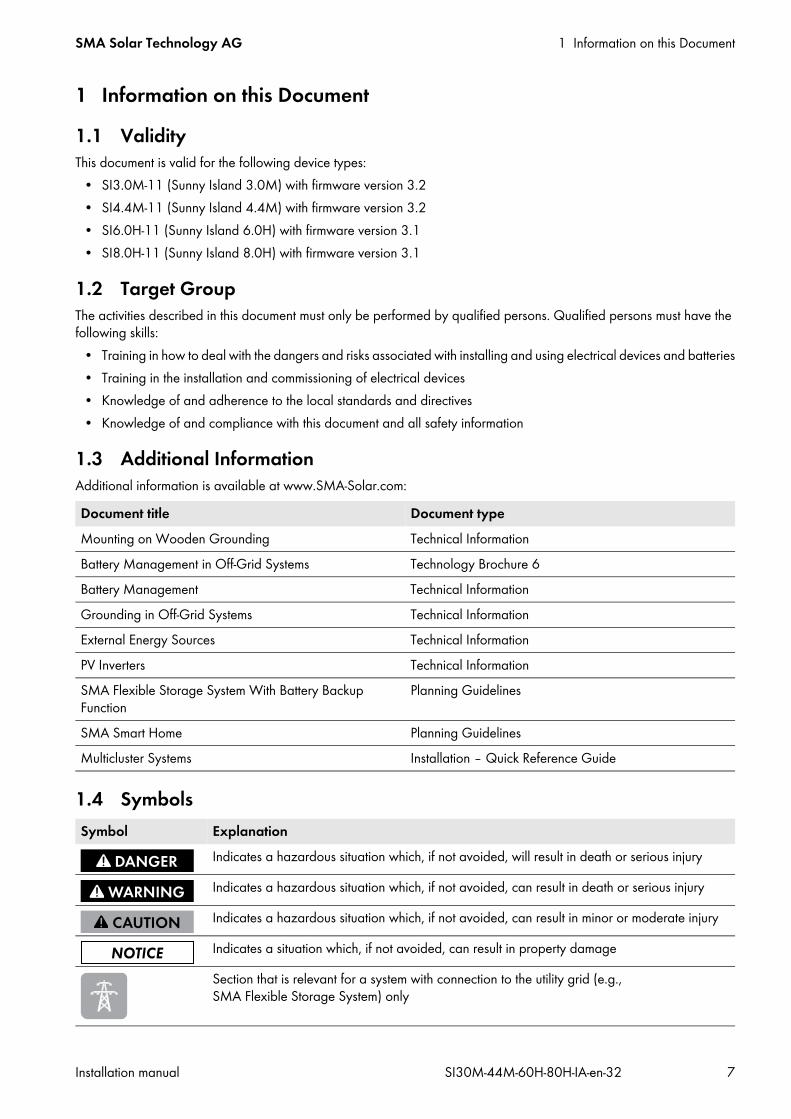
1 Information on this Document1.1 ValidityThis document is valid for the following device types:
• SI3.0M-11 (Sunny Island 3.0M) with firmware version 3.2• SI4.4M-11 (Sunny Island 4.4M) with firmware version 3.2• SI6.0H-11 (Sunny Island 6.0H) with firmware version 3.1• SI8.0H-11 (Sunny Island 8.0H) with firmware version 3.1
1.2 Target GroupThe activities described in this document must only be performed by qualified persons. Qualified persons must have the following skills:
• Training in how to deal with the dangers and risks associated with installing and using electrical devices and batteries• Training in the installation and commissioning of electrical devices• Knowledge of and adherence to the local standards and directives• Knowledge of and compliance with this document and all safety information
1.3 Additional InformationAdditional information is available at www.SMA-Solar.com:
1.4 Symbols
Document title Document typeMounting on Wooden Grounding Technical InformationBattery Management in Off-Grid Systems Technology Brochure 6Battery Management Technical InformationGrounding in Off-Grid Systems Technical InformationExternal Energy Sources Technical InformationPV Inverters Technical InformationSMA Flexible Storage System With Battery Backup Function
Planning Guidelines
SMA Smart Home Planning GuidelinesMulticluster Systems Installation – Quick Reference Guide
Symbol ExplanationIndicates a hazardous situation which, if not avoided, will result in death or serious injury
Indicates a hazardous situation which, if not avoided, can result in death or serious injury
Indicates a hazardous situation which, if not avoided, can result in minor or moderate injury
Indicates a situation which, if not avoided, can result in property damage
Section that is relevant for a system with connection to the utility grid (e.g., SMA Flexible Storage System) only
1 Information on this Document SMA Solar Technology AG
8 SI30M-44M-60H-80H-IA-en-32 Installation manual
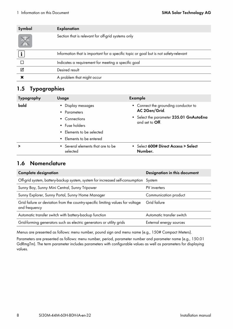
1.5 Typographies
1.6 Nomenclature
Menus are presented as follows: menu number, pound sign and menu name (e.g., 150# Compact Meters).Parameters are presented as follows: menu number, period, parameter number and parameter name (e.g., 150.01 GdRmgTm). The term parameter includes parameters with configurable values as well as parameters for displaying values.
Section that is relevant for off-grid systems only
Information that is important for a specific topic or goal but is not safety-relevant
Indicates a requirement for meeting a specific goal Desired result A problem that might occur
Typography Usage Examplebold • Display messages
• Parameters• Connections• Fuse holders• Elements to be selected• Elements to be entered
• Connect the grounding conductor to AC 2Gen/Grid.
• Select the parameter 235.01 GnAutoEna and set to Off.
> • Several elements that are to be selected
• Select 600# Direct Access > Select Number.
Complete designation Designation in this documentOff-grid system, battery-backup system, system for increased self-consumption SystemSunny Boy, Sunny Mini Central, Sunny Tripower PV invertersSunny Explorer, Sunny Portal, Sunny Home Manager Communication productGrid failure or deviation from the country-specific limiting values for voltage and frequency
Grid failure
Automatic transfer switch with battery-backup function Automatic transfer switchGrid-forming generators such as electric generators or utility grids External energy sources
Symbol Explanation
SMA Solar Technology AG 2 Safety
Installation manual SI30M-44M-60H-80H-IA-en-32 9
2 Safety2.1 Intended UseThe Sunny Island is a battery inverter that controls the electrical energy balance in an off-grid system, in a battery-backup system or in a system for increased self-consumption. In a battery-backup system, you can also use the Sunny Island for increased self-consumption.The Sunny Island is suitable for use indoors and in weather-protected outdoor areas. The Sunny Island must only be used as stationary equipment.The grid configuration of the generator or the utility grid must be a TN or TT system. Cables with copper wires must be used for the installation.Use this product only in accordance with the information provided in the enclosed documentation and with the locally applicable standards and directives. Any other application may cause personal injury or property damage.Device types SI3.0M-11 and SI4.4M-11 do not support all mentioned systems. Only device types SI6.0H-11 and SI8.0H-11 are suitable for single-phase single-cluster systems and three-phase multicluster systems (see the quick reference guide “Off-Grid Systems” or “Multicluster Systems”).The Sunny Island is not suitable for supplying life-sustaining medical devices. A power outage must not lead to personal injury.AC sources (such as PV inverters) can be used in off-grid systems and battery-backup systems for energy supply. Too much power from the AC sources in the stand-alone grid or with battery-backup systems in a battery-backup grid can lead to system failures. The maximum output power of the AC sources must be observed in off-grid systems and battery-backup systems (see Section 10 "Technical Data", page 101). The powers of the individual Sunny Island inverters are added to yield the total maximum power.The Sunny Island uses batteries for the storage of energy. The nominal voltage of the battery must correspond to the input voltage on the DC connection. A fuse switch-disconnector (e.g., BatFuse) must be installed between the battery and the Sunny Island. The battery room must be ventilated in accordance with the requirements of the battery manufacturer and with the locally applicable standards and directives (see documentation of the battery manufacturer). If connecting a lithium-ion battery, the following must be observed:
• The lithium-ion battery must comply with the locally applicable standards and directives and be intrinsically safe.• Battery management of the lithium-ion battery must be compatible with the Sunny Island (see “Safety Information”
in the quick reference guide for the relevant system).In off-grid systems with lead-acid batteries only, a maximum of four Sunny Island Charger charge controllers can be connected per cluster. The battery management must record the DC current when charging and discharging the battery. A battery current sensor may be installed to allow precise measurement of the battery current. The Sunny Island is not suitable for establishing a DC distribution grid.The Sunny Island can control various devices in the system (e.g., load-shedding contactors) via two multifunction relays. The multifunction relays are not suitable for controlling functions that may endanger persons in the event of a malfunction of the multifunction relays, e.g., if there is insufficient redundancy in the ventilation of the battery room.Use this product only in accordance with the information provided in the enclosed documentation and with the locally applicable standards and directives. Any other application may cause personal injury or property damage.Alterations to the product, e.g., modifications or conversions, are only permitted with the express written permission of SMA Solar Technology AG. Unauthorized alterations will void guarantee and warranty claims and usually void the operating license. SMA Solar Technology AG shall not be held liable for any damage caused by such alterations. Any use of the product other than that described in the Intended Use section does not qualify as the intended use.The enclosed documentation is an integral part of this product. Keep the documentation in a convenient place for future reference and observe all instructions contained therein.The type label must remain permanently attached to the product.
2 Safety SMA Solar Technology AG
10 SI30M-44M-60H-80H-IA-en-32 Installation manual
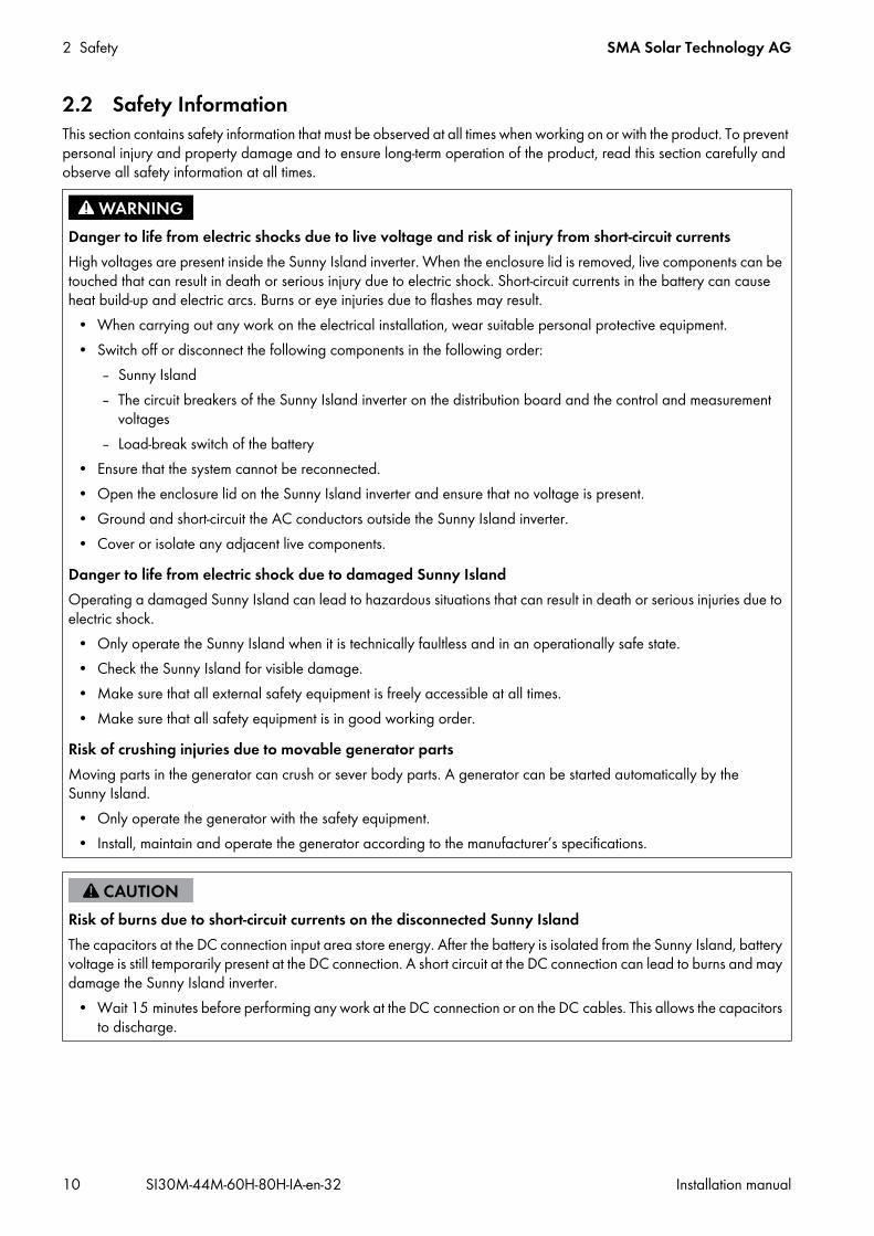
2.2 Safety InformationThis section contains safety information that must be observed at all times when working on or with the product. To prevent personal injury and property damage and to ensure long-term operation of the product, read this section carefully and observe all safety information at all times.
Danger to life from electric shocks due to live voltage and risk of injury from short-circuit currentsHigh voltages are present inside the Sunny Island inverter. When the enclosure lid is removed, live components can be touched that can result in death or serious injury due to electric shock. Short-circuit currents in the battery can cause heat build-up and electric arcs. Burns or eye injuries due to flashes may result.
• When carrying out any work on the electrical installation, wear suitable personal protective equipment.• Switch off or disconnect the following components in the following order:
– Sunny Island– The circuit breakers of the Sunny Island inverter on the distribution board and the control and measurement
voltages– Load-break switch of the battery
• Ensure that the system cannot be reconnected.• Open the enclosure lid on the Sunny Island inverter and ensure that no voltage is present.• Ground and short-circuit the AC conductors outside the Sunny Island inverter.• Cover or isolate any adjacent live components.
Danger to life from electric shock due to damaged Sunny IslandOperating a damaged Sunny Island can lead to hazardous situations that can result in death or serious injuries due to electric shock.
• Only operate the Sunny Island when it is technically faultless and in an operationally safe state.• Check the Sunny Island for visible damage.• Make sure that all external safety equipment is freely accessible at all times.• Make sure that all safety equipment is in good working order.
Risk of crushing injuries due to movable generator partsMoving parts in the generator can crush or sever body parts. A generator can be started automatically by the Sunny Island.
• Only operate the generator with the safety equipment.• Install, maintain and operate the generator according to the manufacturer’s specifications.
Risk of burns due to short-circuit currents on the disconnected Sunny IslandThe capacitors at the DC connection input area store energy. After the battery is isolated from the Sunny Island, battery voltage is still temporarily present at the DC connection. A short circuit at the DC connection can lead to burns and may damage the Sunny Island inverter.
• Wait 15 minutes before performing any work at the DC connection or on the DC cables. This allows the capacitors to discharge.
SMA Solar Technology AG 2 Safety
Installation manual SI30M-44M-60H-80H-IA-en-32 11
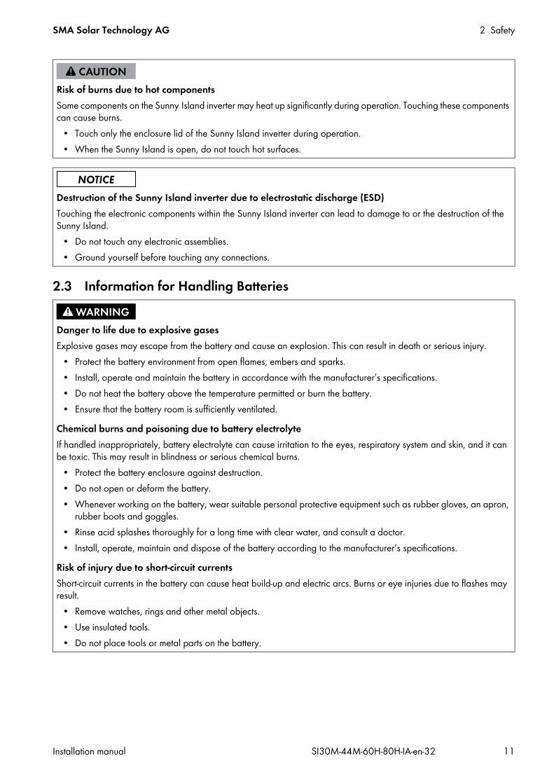
2.3 Information for Handling Batteries
Risk of burns due to hot componentsSome components on the Sunny Island inverter may heat up significantly during operation. Touching these components can cause burns.
• Touch only the enclosure lid of the Sunny Island inverter during operation.• When the Sunny Island is open, do not touch hot surfaces.
Destruction of the Sunny Island inverter due to electrostatic discharge (ESD)Touching the electronic components within the Sunny Island inverter can lead to damage to or the destruction of the Sunny Island.
• Do not touch any electronic assemblies.• Ground yourself before touching any connections.
Danger to life due to explosive gasesExplosive gases may escape from the battery and cause an explosion. This can result in death or serious injury.
• Protect the battery environment from open flames, embers and sparks.• Install, operate and maintain the battery in accordance with the manufacturer’s specifications.• Do not heat the battery above the temperature permitted or burn the battery.• Ensure that the battery room is sufficiently ventilated.
Chemical burns and poisoning due to battery electrolyteIf handled inappropriately, battery electrolyte can cause irritation to the eyes, respiratory system and skin, and it can be toxic. This may result in blindness or serious chemical burns.
• Protect the battery enclosure against destruction.• Do not open or deform the battery.• Whenever working on the battery, wear suitable personal protective equipment such as rubber gloves, an apron,
rubber boots and goggles.• Rinse acid splashes thoroughly for a long time with clear water, and consult a doctor.• Install, operate, maintain and dispose of the battery according to the manufacturer’s specifications.
Risk of injury due to short-circuit currentsShort-circuit currents in the battery can cause heat build-up and electric arcs. Burns or eye injuries due to flashes may result.
• Remove watches, rings and other metal objects.• Use insulated tools.• Do not place tools or metal parts on the battery.

2 Safety SMA Solar Technology AG
12 SI30M-44M-60H-80H-IA-en-32 Installation manual
Risk of burns due to hot battery componentsImproper battery connection may result in excessively high transition resistances. Excessive transition resistances give rise to localized heat build-up. Heat build-up can cause burns.
• Ensure that all pole connectors are connected with the connecting torque specified by the battery manufacturer.• Ensure that all DC cables are connected with the connecting torque specified by the battery manufacturer.
Permanent damage to the battery due to improper handlingImproper storage, transport, set-up or maintenance of the battery can cause it to become permanently damaged. Logs can help to determine the cause.
• Comply with all requirements of the battery manufacturer with regard to storage, transport and mounting location.• Check and log the status of the battery before commissioning and before performing maintenance work:
• Check the battery for visible damage and log.• Measure and log the fill level and acid density of FLA batteries.• In the case of lead-acid batteries, measure and log the voltages of the individual cells.• Perform and log the test routines required by the battery manufacturer.
Tip: Many battery manufacturers provide suitable logs.Damage to the battery due to incorrect settingsThe set battery parameters influence the charging behavior of the Sunny Island inverter. The battery can be damaged by incorrect settings of the battery type, nominal voltage and capacity parameters.
• Ensure that the values recommended by the battery manufacturer are set (refer to the technical data of the battery in the manufacturer documentation). Note that the battery charging behavior names used by SMA Solar Technology AG and the battery manufacturer may, in some cases, differ in meaning (for the battery charging behavior of the Sunny Island inverter, see technical information “Battery Management”).
• Set the battery capacity for a ten-hour electric discharge (C10) The battery manufacturer specifies the battery capacity in relation to discharge time.
Prior damage to batteriesBatteries may have suffered prior damage due to production defects. Logs can help to determine the cause.
• Check and log the status of the battery before commissioning and each time before performing maintenance work:
Performance impairment of batteriesTransition resistances can impair the performance of the batteries.
• Note the torques when connecting the battery.

SMA Solar Technology AG 3 Scope of Delivery
Installation manual SI30M-44M-60H-80H-IA-en-32 13
3 Scope of DeliveryCheck the scope of delivery for completeness and any externally visible damage. Contact your distributor if the scope of delivery is incomplete or damaged.
Figure 1: Components included in the scope of delivery
Position Quantity Designation Position Quantity DesignationA 1 Sunny Island R 2 M25 cable glandB 2 Ventilation grid S 2 Counter nut for M25 cable
glandC 1 Wall mounting bracket T 2 M32 cable glandD 2 Hexagon socket screw M6x10 U 2 Counter nut for M32 cable
glandV 1 Filler plug M20
E 2 Hexagon socket screw M6x16*
W 1 Filler plug M25X 1 Sealing compound
F 2 Hexagon socket screw M8x20 Y 1 Black CAT5e data cable, 2 mG 2 Fender washer M8 Z 2 Silicon tube 10 mm x 500 mmH 2 Spring washer M8 a 1 Cable support sleeve for one
cableI 2 M6 conical spring washer*
* 1 spare part for the enclosure lid included
b 2 Cable support sleeve for two cables
K 1 Clamping bracket c 1 Installation manual, operating manual, quick reference guides: “SMA Flexible Storage System”, “SMA Flexible Storage System with Battery Backup Function”, “Off-Grid Systems”
L 1 Battery temperature sensorM 1 2-pole terminalN 2 3-pole terminalO 2 4-pole terminalP 1 M20 cable gland d 1 Label “VDE 0126-1-1”Q 1 Counter nut for M20 cable
gland1 Warning label for
battery-backup system
3 Scope of Delivery SMA Solar Technology AG
14 SI30M-44M-60H-80H-IA-en-32 Installation manual
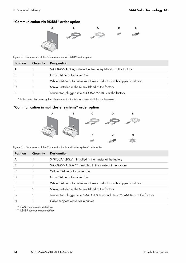
“Communication via RS485” order option
Figure 2: Components of the “Communication via RS485” order option
“Communication in multicluster systems” order option
Figure 3: Components of the “Communication in multicluster systems” order option
Position Quantity DesignationA 1 SI-COMSMA.BGx, installed in the Sunny Island* at the factory
* In the case of a cluster system, the communication interface is only installed in the master.
B 1 Gray CAT5e data cable, 5 mC 1 White CAT5e data cable with three conductors with stripped insulationD 1 Screw, installed in the Sunny Island at the factoryE 1 Terminator, plugged into SI-COMSMA.BGx at the factory
Position Quantity DesignationA 1 SI-SYSCAN.BGx* , installed in the master at the factory
* CAN communication interface
B 1 SI-COMSMA.BGx** , installed in the master at the factory
** RS485 communication interface
C 1 Yellow CAT5e data cable, 5 mD 1 Gray CAT5e data cable, 5 mE 1 White CAT5e data cable with three conductors with stripped insulationF 2 Screw, installed in the Sunny Island at the factoryG 2 Terminator, plugged into SI-SYSCAN.BGx and SI-COMSMA.BGx at the factoryH 1 Cable support sleeve for 4 cables

SMA Solar Technology AG 3 Scope of Delivery
Installation manual SI30M-44M-60H-80H-IA-en-32 15
“Communication via Speedwire” order option (e.g., SMA Flexible Storage System)
Figure 4: Components of the “Communication via Speedwire” order option
Position Quantity DesignationA 1 Speedwire data module, installed in the master at the factoryB 3 Spacer*
* Two spacers are required for installation of the Speedwire data module. One spacer is a spare part.
C 1 ScrewD 1 Cable support sleeveE 1 Filler plugF 1 Installation manualG 1 Network cable, 5 m

4 Additional Tools Required SMA Solar Technology AG
16 SI30M-44M-60H-80H-IA-en-32 Installation manual
4 Additional Tools RequiredTools ExplanationDrill ‒Drill bit Mounting of the wall mounting bracketAllen key, AF 5 ‒Torque wrench Attachment: AF 5
Measurement range: 4 Nm to 12 NmCrimping pliers Crimping of the DC cable terminal lugsCrimping tool Crimping of the bootlace ferrulesFlat-blade screwdriver Connection of the control and measuring cables to the terminalsCurrent clamp Measuring of the battery currentMeasuring device for voltage measurement
Measuring of the AC voltages in the system and measuring of the battery voltage
SMA Solar Technology AG 5 Product Description
Installation manual SI30M-44M-60H-80H-IA-en-32 17
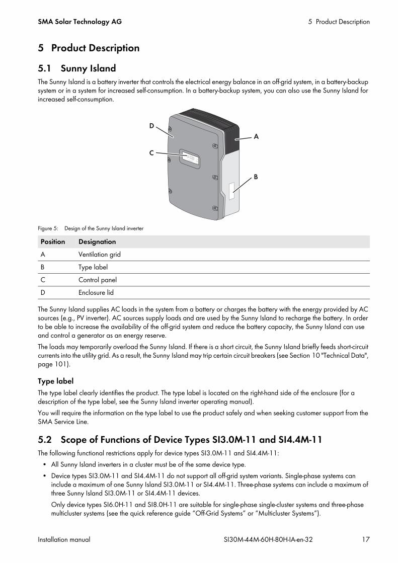
5 Product Description5.1 Sunny IslandThe Sunny Island is a battery inverter that controls the electrical energy balance in an off-grid system, in a battery-backup system or in a system for increased self-consumption. In a battery-backup system, you can also use the Sunny Island for increased self-consumption.
Figure 5: Design of the Sunny Island inverter
The Sunny Island supplies AC loads in the system from a battery or charges the battery with the energy provided by AC sources (e.g., PV inverter). AC sources supply loads and are used by the Sunny Island to recharge the battery. In order to be able to increase the availability of the off-grid system and reduce the battery capacity, the Sunny Island can use and control a generator as an energy reserve.The loads may temporarily overload the Sunny Island. If there is a short circuit, the Sunny Island briefly feeds short-circuit currents into the utility grid. As a result, the Sunny Island may trip certain circuit breakers (see Section 10 "Technical Data", page 101).
Type labelThe type label clearly identifies the product. The type label is located on the right-hand side of the enclosure (for a description of the type label, see the Sunny Island inverter operating manual).You will require the information on the type label to use the product safely and when seeking customer support from the SMA Service Line.
5.2 Scope of Functions of Device Types SI3.0M-11 and SI4.4M-11The following functional restrictions apply for device types SI3.0M-11 and SI4.4M-11:
• All Sunny Island inverters in a cluster must be of the same device type.• Device types SI3.0M-11 and SI4.4M-11 do not support all off-grid system variants. Single-phase systems can
include a maximum of one Sunny Island SI3.0M-11 or SI4.4M-11. Three-phase systems can include a maximum of three Sunny Island SI3.0M-11 or SI4.4M-11 devices.Only device types SI6.0H-11 and SI8.0H-11 are suitable for single-phase single-cluster systems and three-phase multicluster systems (see the quick reference guide “Off-Grid Systems” or “Multicluster Systems”).
Position DesignationA Ventilation gridB Type labelC Control panelD Enclosure lid
5 Product Description SMA Solar Technology AG
18 SI30M-44M-60H-80H-IA-en-32 Installation manual
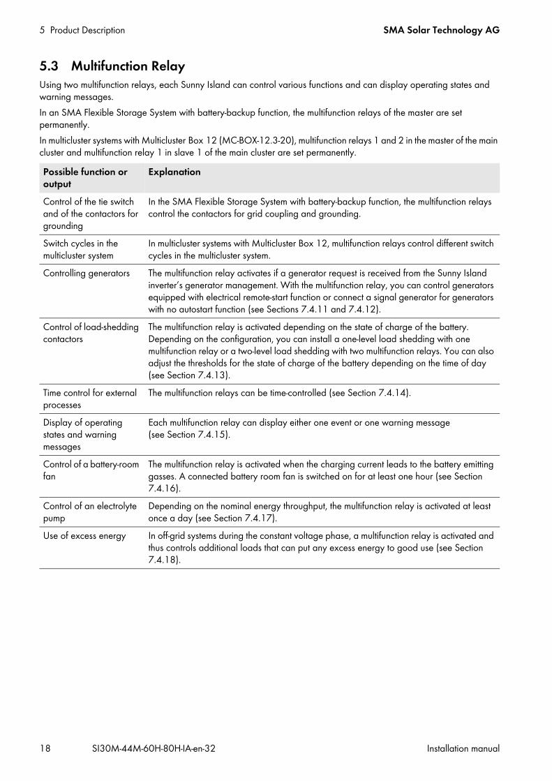
5.3 Multifunction RelayUsing two multifunction relays, each Sunny Island can control various functions and can display operating states and warning messages.In an SMA Flexible Storage System with battery-backup function, the multifunction relays of the master are set permanently.In multicluster systems with Multicluster Box 12 (MC-BOX-12.3-20), multifunction relays 1 and 2 in the master of the main cluster and multifunction relay 1 in slave 1 of the main cluster are set permanently.Possible function or output
Explanation
Control of the tie switch and of the contactors for grounding
In the SMA Flexible Storage System with battery-backup function, the multifunction relays control the contactors for grid coupling and grounding.
Switch cycles in the multicluster system
In multicluster systems with Multicluster Box 12, multifunction relays control different switch cycles in the multicluster system.
Controlling generators The multifunction relay activates if a generator request is received from the Sunny Island inverter’s generator management. With the multifunction relay, you can control generators equipped with electrical remote-start function or connect a signal generator for generators with no autostart function (see Sections 7.4.11 and 7.4.12).
Control of load-shedding contactors
The multifunction relay is activated depending on the state of charge of the battery. Depending on the configuration, you can install a one-level load shedding with one multifunction relay or a two-level load shedding with two multifunction relays. You can also adjust the thresholds for the state of charge of the battery depending on the time of day (see Section 7.4.13).
Time control for external processes
The multifunction relays can be time-controlled (see Section 7.4.14).
Display of operating states and warning messages
Each multifunction relay can display either one event or one warning message (see Section 7.4.15).
Control of a battery-room fan
The multifunction relay is activated when the charging current leads to the battery emitting gasses. A connected battery room fan is switched on for at least one hour (see Section 7.4.16).
Control of an electrolyte pump
Depending on the nominal energy throughput, the multifunction relay is activated at least once a day (see Section 7.4.17).
Use of excess energy In off-grid systems during the constant voltage phase, a multifunction relay is activated and thus controls additional loads that can put any excess energy to good use (see Section 7.4.18).

SMA Solar Technology AG 5 Product Description
Installation manual SI30M-44M-60H-80H-IA-en-32 19
5.4 Communication5.4.1 Communication InterfacesThe Sunny Island is equipped with two interface slots for the connection of SMA communication interfaces.
Interface slot SICOMSMAThe interface slot SICOMSMA is for connecting the Speedwire data module SWDMSI-xx or the RS485 communication interface SI-COMSMA.BGx.The Speedwire data module SWDMSI-xx allows the Sunny Island inverter to be integrated into a Speedwire network. Speedwire is a cable-based type of communication based on the Ethernet standard and the communication protocol SMA Data2+. This enables inverter-optimized 10/100 Mbit data transmission between Speedwire devices, e.g., between Sunny Island and Sunny Home Manager.The SI-COMSMA.BGx communication interface allows the Sunny Island inverter to be integrated into an RS485 communication bus. You can connect the Sunny Island to the following products using RS485:
• SMA communication products (e.g., Sunny WebBox)• PV inverters• Wind power inverters• Extension cluster masters
If the Sunny Island inverters are ordered with the RS485 communication interface SI-COMSMA.BGx or with the Speedwire data module SWDMSI-xx, the Sunny Island inverters are delivered with premounted communication interfaces (Components of the optional communication interface see Section 3, page 13).
Interface slot SISYSCANOn Sunny Island device types SI6.0H-11 or SI8.0H-11, the interface slot SISYSCAN is for connecting the multicluster data module SI-SYSCAN.BGx.In a multicluster system, the masters of the clusters must communicate with each other via a separate CAN bus. An SI-SYSCAN.BGx communication interface must be installed in each master for multicluster communication.If the Sunny Island inverters are ordered with the communication interface SI-SYSCAN.BGx, the masters are delivered with premounted communication interfaces (components of the optional communication interface see Section 3, page 13).
5.4.2 Compatible Communication ProductsSunny Home Manager and Sunny PortalThe Sunny Home Manager is a device for PV system monitoring and for controlling loads in households with PV systems. The Sunny Home Manager and the Sunny Island inverter communicate via Speedwire and are a substantial part of the SMA Flexible Storage System (see quick reference guide of the Sunny Island inverter).Sunny Portal is an Internet portal for visualization of the data of the PV system, of SMA radio-controlled sockets and of other components of the SMA Flexible Storage System. In addition, Sunny Portal serves as a user interface for configuring the Sunny Home Manager and SMA radio-controlled sockets (see user manual of the SUNNY HOME MANAGER in SUNNY PORTAL).
Sunny ExplorerWith the Sunny Explorer software, you can visualize and manage the data of your Sunny Island system. You can also use it to configure single devices or entire device classes in your system.To enable this, the Sunny Explorer software must be installed on a computer that is connected to the Sunny Island via Speedwire (see user manual of Sunny Explorer).
6 Mounting SMA Solar Technology AG
20 SI30M-44M-60H-80H-IA-en-32 Installation manual
6 Mounting6.1 Requirements for MountingMounting location: A stable, non-flammable support surface must be used at the mounting location, e.g., concrete or masonry. In the
living area, ensure that the support surface is not made of drywall or similar. When in operation, the Sunny Island makes noises that can be perceived as annoying.
The mounting location must be suitable for the weight and dimensions of the Sunny Island inverter (see Section 10 "Technical Data", page 101).
The mounting location must be clear and safely accessible at all times without the need for any auxiliary equipment (e.g., scaffolding or lifting platforms). Non-fulfillment of these criteria may restrict servicing.
The mounting location must not hinder access to disconnection devices. The mounting location must not be exposed to direct solar irradiation. Direct solar irradiation can cause the
Sunny Island to overheat. Climatic conditions must be met (see Section 10 "Technical Data", page 101). The mounting location must be less than 3,000 m above MSL. From altitudes of 2,000 m above MSL, the power
decreases by 0.5% every 100 m. The ambient temperature should be below 40°C. This will ensure the optimum operation of the Sunny Island inverter
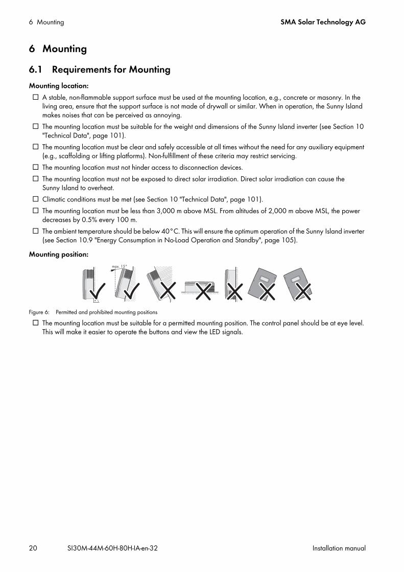
(see Section 10.9 "Energy Consumption in No-Load Operation and Standby", page 105).Mounting position:
Figure 6: Permitted and prohibited mounting positions The mounting location must be suitable for a permitted mounting position. The control panel should be at eye level.
This will make it easier to operate the buttons and view the LED signals.
SMA Solar Technology AG 6 Mounting
Installation manual SI30M-44M-60H-80H-IA-en-32 21
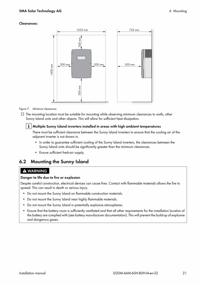
Clearances:
Figure 7: Minimum clearances The mounting location must be suitable for mounting while observing minimum clearances to walls, other
Sunny Island units and other objects. This will allow for sufficient heat dissipation.
6.2 Mounting the Sunny Island
Multiple Sunny Island inverters installed in areas with high ambient temperaturesThere must be sufficient clearance between the Sunny Island inverters to ensure that the cooling air of the adjacent inverter is not drawn in.
• In order to guarantee sufficient cooling of the Sunny Island inverters, the clearances between the Sunny Island units should be significantly greater than the minimum clearances.
• Ensure sufficient fresh-air supply.
Danger to life due to fire or explosionDespite careful construction, electrical devices can cause fires. Contact with flammable materials allows the fire to spread. This can result in death or serious injury.
• Do not mount the Sunny Island on flammable construction materials.• Do not mount the Sunny Island near highly flammable materials.• Do not mount the Sunny Island in potentially explosive atmospheres.• Ensure that the battery room is sufficiently ventilated and that all other requirements for the installation location of
the battery are complied with (see battery manufacturer documentation). This will prevent the build-up of explosive and dangerous gases.
6 Mounting SMA Solar Technology AG
22 SI30M-44M-60H-80H-IA-en-32 Installation manual
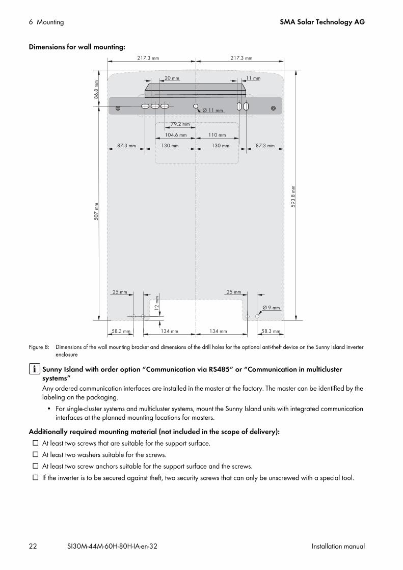
Dimensions for wall mounting:
Figure 8: Dimensions of the wall mounting bracket and dimensions of the drill holes for the optional anti-theft device on the Sunny Island inverter enclosure
Additionally required mounting material (not included in the scope of delivery): At least two screws that are suitable for the support surface. At least two washers suitable for the screws. At least two screw anchors suitable for the support surface and the screws. If the inverter is to be secured against theft, two security screws that can only be unscrewed with a special tool.
Sunny Island with order option “Communication via RS485” or “Communication in multicluster systems”Any ordered communication interfaces are installed in the master at the factory. The master can be identified by the labeling on the packaging.
• For single-cluster systems and multicluster systems, mount the Sunny Island units with integrated communication interfaces at the planned mounting locations for masters.
SMA Solar Technology AG 6 Mounting
Installation manual SI30M-44M-60H-80H-IA-en-32 23
Procedure:1. At the mounting location, mark the position of the drill holes using the wall mounting bracket. Use at least one hole
on the right side of the wall mounting bracket and one on the left.2. Ensure that there are no electric lines or other supply lines in the wall behind the marked positions.3. Drill the holes and insert the screw anchors.4. Secure the wall mounting bracket horizontally to the wall using screws and washers.5. If the Sunny Island is to be secured against theft, mark the drill holes for the anti-theft device. Use at least one hole
on the right and one on the left.
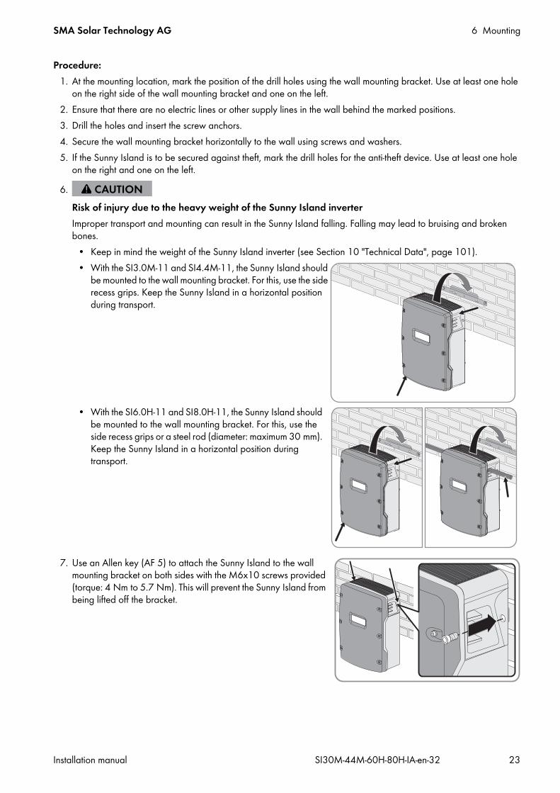
7. Use an Allen key (AF 5) to attach the Sunny Island to the wall mounting bracket on both sides with the M6x10 screws provided (torque: 4 Nm to 5.7 Nm). This will prevent the Sunny Island from being lifted off the bracket.
6.Risk of injury due to the heavy weight of the Sunny Island inverterImproper transport and mounting can result in the Sunny Island falling. Falling may lead to bruising and broken bones.
• Keep in mind the weight of the Sunny Island inverter (see Section 10 "Technical Data", page 101).• With the SI3.0M-11 and SI4.4M-11, the Sunny Island should
be mounted to the wall mounting bracket. For this, use the side recess grips. Keep the Sunny Island in a horizontal position during transport.
• With the SI6.0H-11 and SI8.0H-11, the Sunny Island should be mounted to the wall mounting bracket. For this, use the side recess grips or a steel rod (diameter: maximum 30 mm). Keep the Sunny Island in a horizontal position during transport.
6 Mounting SMA Solar Technology AG
24 SI30M-44M-60H-80H-IA-en-32 Installation manual
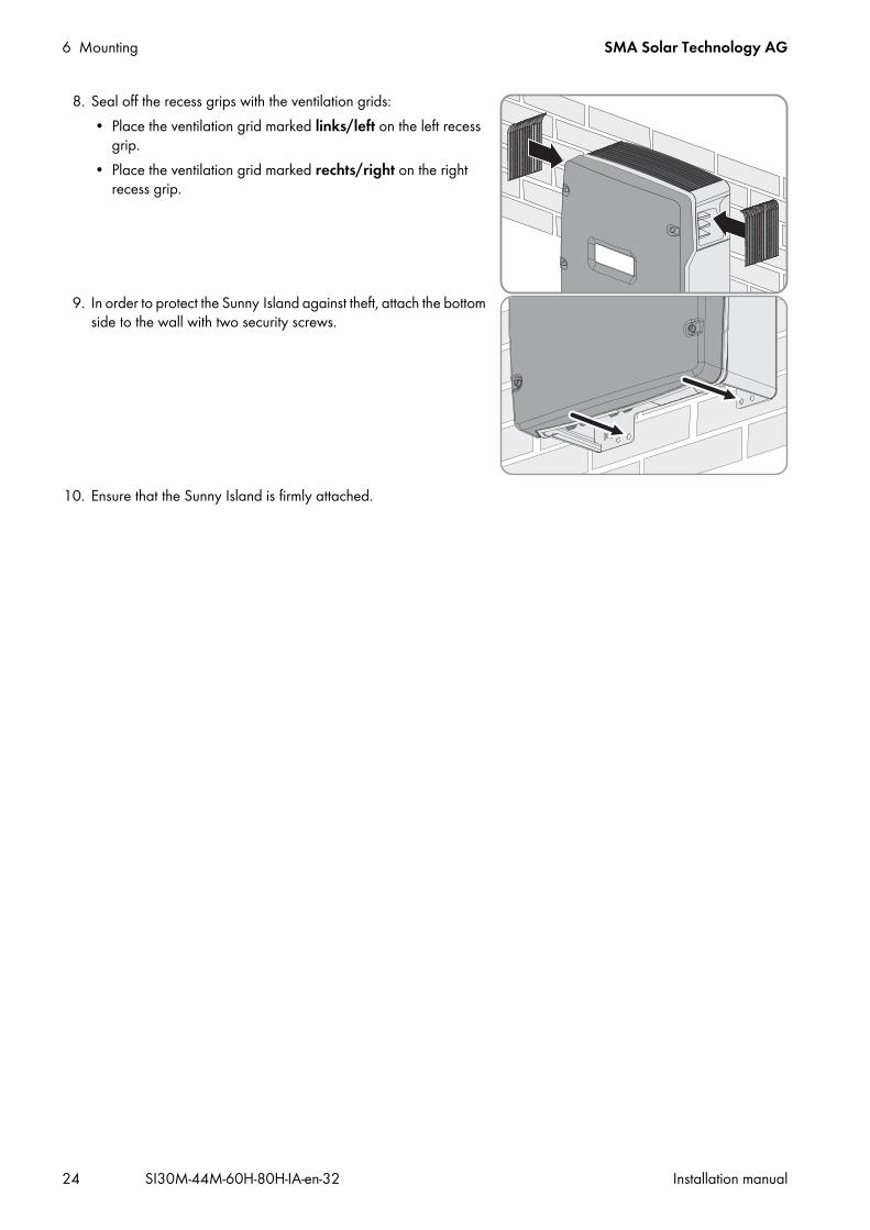
8. Seal off the recess grips with the ventilation grids:• Place the ventilation grid marked links/left on the left recess
grip.• Place the ventilation grid marked rechts/right on the right
recess grip.
9. In order to protect the Sunny Island against theft, attach the bottom side to the wall with two security screws.
10. Ensure that the Sunny Island is firmly attached.

SMA Solar Technology AG 7 Electrical Connection
Installation manual SI30M-44M-60H-80H-IA-en-32 25
7 Electrical Connection7.1 Content and Structure of the SectionThe sub-sections differ in their structure. Some sub-sections refer to the correct connection of devices, others refer to basic procedures.An overview detailing which contents the sub-sections describe and which contents should be read and adhered to can be found in the following table.Section Explanation7.2 Connection Area Graphic overview of the connection area7.3 Connecting the Grounding Conductor
in Systems with a Grounded BatteryFor systems with a grounded battery, this section must be read and observed.
7.4 Connecting the Components Information on the connection and circuitry of individual devices with specification of connections on the Sunny Island
7.5 Connecting the Cables Correct connection of the cables to the respective connectionsYou must read and observe the sections for the connections used.
7.6 Checking the Wiring You must read and observe the section for the connections used.7.7 Sealing and Closing the Sunny Island You must read and observe this section.7.8 Inserting the Fuse Links in the Fuse
Switch-Disconnector BatFuseYou must read and observe this section.
7 Electrical Connection SMA Solar Technology AG
26 SI30M-44M-60H-80H-IA-en-32 Installation manual
7.2 Connection Area
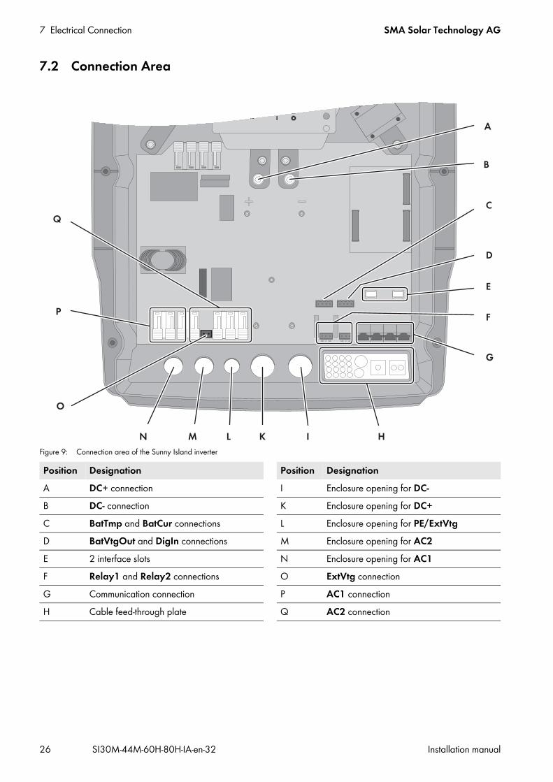
Figure 9: Connection area of the Sunny Island inverter
Position Designation Position DesignationA DC+ connection I Enclosure opening for DC-B DC- connection K Enclosure opening for DC+C BatTmp and BatCur connections L Enclosure opening for PE/ExtVtgD BatVtgOut and DigIn connections M Enclosure opening for AC2E 2 interface slots N Enclosure opening for AC1F Relay1 and Relay2 connections O ExtVtg connectionG Communication connection P AC1 connectionH Cable feed-through plate Q AC2 connection

SMA Solar Technology AG 7 Electrical Connection
Installation manual SI30M-44M-60H-80H-IA-en-32 27
7.3 Connecting the Grounding Conductor in Systems with a Grounded Battery
If you ground the battery, you can ground it at the positive terminal or at the negative terminal with a grounding conductor. SMA Solar Technology AG does not recommend grounding the battery. If the battery is grounded, the enclosure of the Sunny Island must also be grounded. This additional grounding is no substitute for the grounding at connections AC1 and AC2.Conductor cross-section:You must determine the required conductor cross-section of the grounding conductor, taking into account the applicable local standards and directives. The calculation of the grounding conductor cross-section depends on the type and size of the connected battery, the external fuse in the BatFuse and the material of the grounding conductor.
Cable requirement: Copper wire Conductor cross-section: maximum 16 mm² The cross-sections of the battery grounding conductor and Sunny Island inverter grounding conductor must be the
same.Procedure:
1. Calculate the cross-section of the grounding conductor.2. Ground the battery at the positive terminal or negative terminal using a conductor with the calculated cross-section.3. Also ground the Sunny Island enclosure using a conductor with the calculated cross-section, as follows:
• Strip off the insulation of the grounding conductor.• Place the clamping bracket over the conductor. Position the
conductor on the left.
Example: Calculation of the grounding conductor cross-sectionGrounding conductor made of copper. The required cross-section of the grounding conductor can be calculated using the following formula:
SCuISCt
= conductor cross-section in mm²= short-circuit current in A= interruption time in s
Typical tripping times for an LV/HRC fuse are around 25 ms for short-circuit currents between 2,000 A and 10,000 A. Grounding with a cross-section of 16 mm² is sufficient for short-circuit currents up to 10,000 A.
7 Electrical Connection SMA Solar Technology AG
28 SI30M-44M-60H-80H-IA-en-32 Installation manual
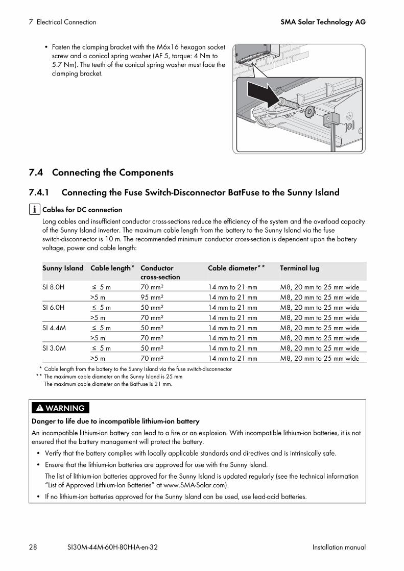
• Fasten the clamping bracket with the M6x16 hexagon socket screw and a conical spring washer (AF 5, torque: 4 Nm to 5.7 Nm). The teeth of the conical spring washer must face the clamping bracket.
7.4 Connecting the Components7.4.1 Connecting the Fuse Switch-Disconnector BatFuse to the Sunny Island
Cables for DC connectionLong cables and insufficient conductor cross-sections reduce the efficiency of the system and the overload capacity of the Sunny Island inverter. The maximum cable length from the battery to the Sunny Island via the fuse switch-disconnector is 10 m. The recommended minimum conductor cross-section is dependent upon the battery voltage, power and cable length:
Sunny Island Cable length*
* Cable length from the battery to the Sunny Island via the fuse switch-disconnector
Conductor cross-section
Cable diameter**
** The maximum cable diameter on the Sunny Island is 25 mm The maximum cable diameter on the BatFuse is 21 mm.
Terminal lug
SI 8.0H ≤ 5 m 70 mm² 14 mm to 21 mm M8, 20 mm to 25 mm wide>5 m 95 mm² 14 mm to 21 mm M8, 20 mm to 25 mm wide
SI 6.0H ≤ 5 m 50 mm² 14 mm to 21 mm M8, 20 mm to 25 mm wide>5 m 70 mm² 14 mm to 21 mm M8, 20 mm to 25 mm wide
SI 4.4M ≤ 5 m 50 mm² 14 mm to 21 mm M8, 20 mm to 25 mm wide>5 m 70 mm² 14 mm to 21 mm M8, 20 mm to 25 mm wide
SI 3.0M ≤ 5 m 50 mm² 14 mm to 21 mm M8, 20 mm to 25 mm wide>5 m 70 mm² 14 mm to 21 mm M8, 20 mm to 25 mm wide
Danger to life due to incompatible lithium-ion batteryAn incompatible lithium-ion battery can lead to a fire or an explosion. With incompatible lithium-ion batteries, it is not ensured that the battery management will protect the battery.
• Verify that the battery complies with locally applicable standards and directives and is intrinsically safe.• Ensure that the lithium-ion batteries are approved for use with the Sunny Island.
The list of lithium-ion batteries approved for the Sunny Island is updated regularly (see the technical information “List of Approved Lithium-Ion Batteries” at www.SMA-Solar.com).
• If no lithium-ion batteries approved for the Sunny Island can be used, use lead-acid batteries.
SMA Solar Technology AG 7 Electrical Connection
Installation manual SI30M-44M-60H-80H-IA-en-32 29
Procedure:1. Ensure that the load-break switch of the BatFuse is open and secured against reconnection.2. On the Sunny Island, remove all screws of the lower enclosure lid using an Allen key (AF 5) and remove the
enclosure lid. Retain the screws and conical spring washers for later use.3. Clean the contact surfaces of the DC+ and DC- connections, for example, with ethanol. This reduces the transition
resistance on the contact surfaces. A low transition resistance increases the system stability and minimizes the risk of damage to the Sunny Island.
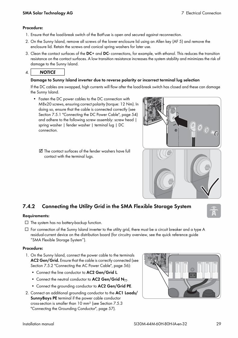
7.4.2 Connecting the Utility Grid in the SMA Flexible Storage SystemRequirements: The system has no battery-backup function. For connection of the Sunny Island inverter to the utility grid, there must be a circuit breaker and a type A
residual-current device on the distribution board (for circuitry overview, see the quick reference guide “SMA Flexible Storage System”).
Procedure:1. On the Sunny Island, connect the power cable to the terminals
AC2 Gen/Grid. Ensure that the cable is correctly connected (see Section 7.5.2 "Connecting the AC Power Cable", page 56):• Connect the line conductor to AC2 Gen/Grid L.• Connect the neutral conductor to AC2 Gen/Grid NTT.• Connect the grounding conductor to AC2 Gen/Grid PE.
2. Connect an additional grounding conductor to the AC1 Loads/SunnyBoys PE terminal if the power cable conductor cross-section is smaller than 10 mm² (see Section 7.5.3 "Connecting the Grounding Conductor", page 57).
4.Damage to Sunny Island inverter due to reverse polarity or incorrect terminal lug selectionIf the DC cables are swapped, high currents will flow after the load-break switch has closed and these can damage the Sunny Island.
• Fasten the DC power cables to the DC connection with M8x20 screws, ensuring correct polarity (torque: 12 Nm). In doing so, ensure that the cable is connected correctly (see Section 7.5.1 "Connecting the DC Power Cable", page 54) and adhere to the following screw assembly: screw head | spring washer | fender washer | terminal lug | DC connection.
The contact surfaces of the fender washers have full contact with the terminal lugs.
7 Electrical Connection SMA Solar Technology AG
30 SI30M-44M-60H-80H-IA-en-32 Installation manual
7.4.3 Connecting the Automatic Transfer Switch in the SMA Flexible Storage System with Battery-Backup Function
7.4.3.1 Automatic Transfer Switch FunctionThe automatic transfer switch separates the utility grid from the battery-backup grid in the SMA Flexible Storage System with battery-backup function. The control cable, measuring cable and power cable link the automatic transfer switch to the Sunny Island (for circuitry overview, see the quick reference guide “SMA Flexible Storage System with Battery Backup Function”).
7.4.3.2 Connecting the AC Power Cables to the Automatic Transfer SwitchThe AC power cables conduct the energy between the battery-backup grid and the Sunny Island (for circuitry overview, see the quick reference guide “SMA Flexible Storage System with Battery Backup Function”).Requirements: In a three-phase SMA Flexible Storage System with battery-backup function, L1 must be assigned to the master,
L2 to slave 1, and L3 to slave 2. This creates a right-hand rotating magnetic field. The power of the AC sources in the battery-backup grid must not exceed the maximum connectable power of the PV
inverters in the SMA Flexible Storage System with battery-backup function (see Section 10.2 "AC2 Connection for Utility Grid and Generator (External Energy Source)", page 102). The powers of the individual Sunny Island inverters are added to yield the total maximum power.
Cable requirements: Copper wire Number of conductors in the cable: 3 Conductor cross-section: 10 mm² to 16 mm² Cable diameter: 9 mm to 18 mm
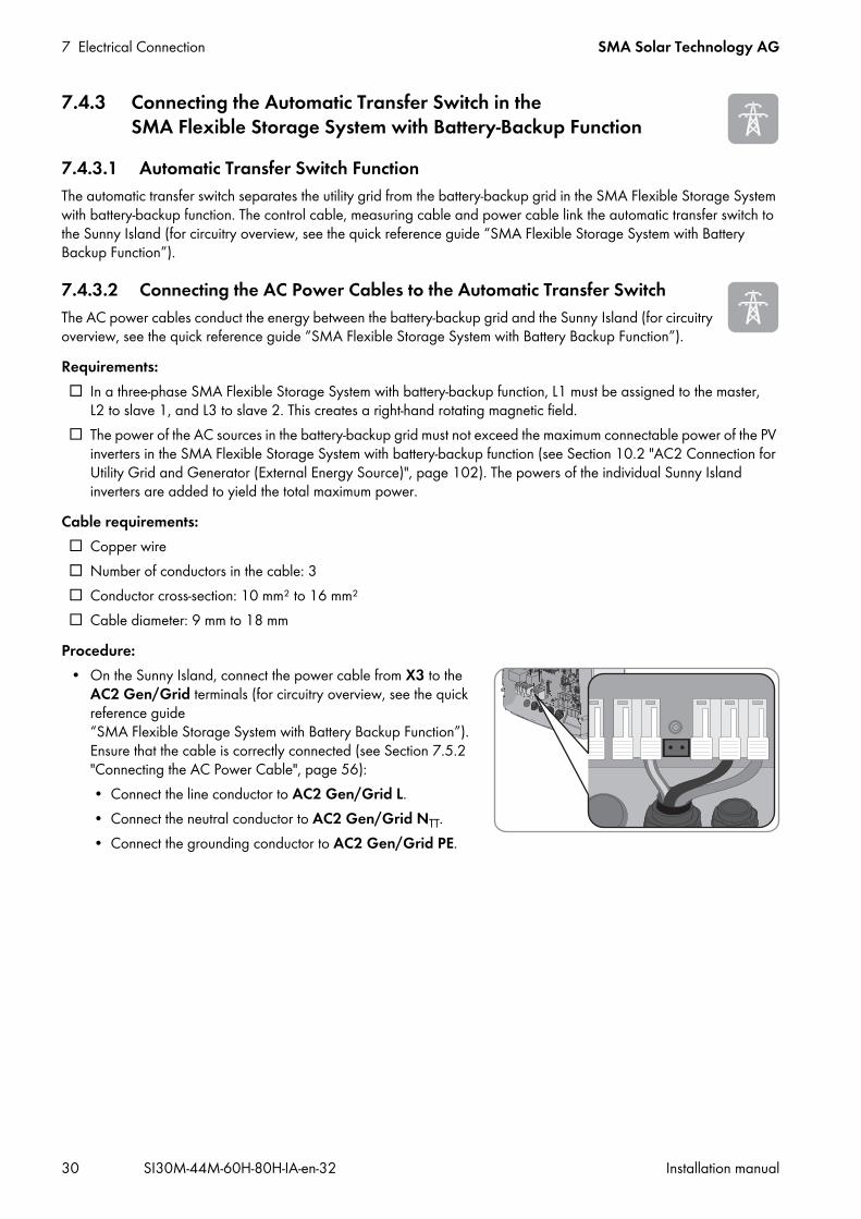
Procedure:• On the Sunny Island, connect the power cable from X3 to the
AC2 Gen/Grid terminals (for circuitry overview, see the quick reference guide “SMA Flexible Storage System with Battery Backup Function”). Ensure that the cable is correctly connected (see Section 7.5.2 "Connecting the AC Power Cable", page 56):• Connect the line conductor to AC2 Gen/Grid L.• Connect the neutral conductor to AC2 Gen/Grid NTT.• Connect the grounding conductor to AC2 Gen/Grid PE.
SMA Solar Technology AG 7 Electrical Connection
Installation manual SI30M-44M-60H-80H-IA-en-32 31
7.4.3.3 Connecting the Control Cables to the Automatic Transfer SwitchThe control cables conduct the control signals of the multifunction relays to the contactors (for circuitry overview, see the quick reference guide “SMA Flexible Storage System with Battery Backup Function”).Procedure:
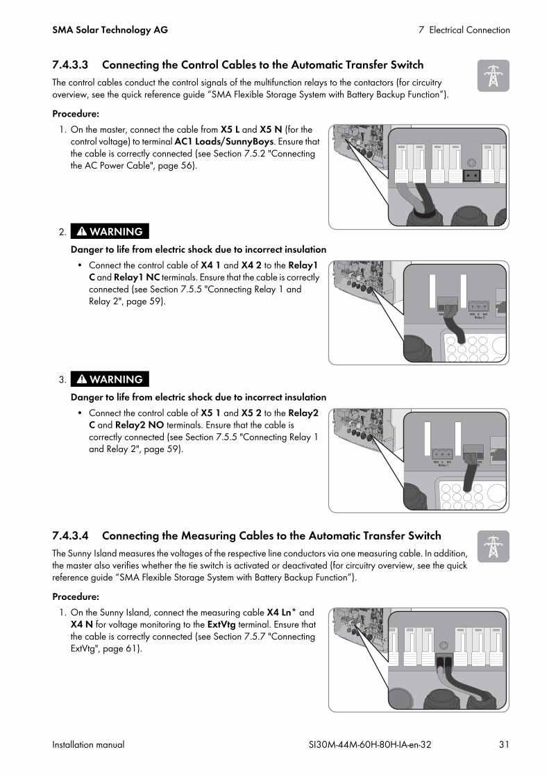
1. On the master, connect the cable from X5 L and X5 N (for the control voltage) to terminal AC1 Loads/SunnyBoys. Ensure that the cable is correctly connected (see Section 7.5.2 "Connecting the AC Power Cable", page 56).
7.4.3.4 Connecting the Measuring Cables to the Automatic Transfer SwitchThe Sunny Island measures the voltages of the respective line conductors via one measuring cable. In addition, the master also verifies whether the tie switch is activated or deactivated (for circuitry overview, see the quick reference guide “SMA Flexible Storage System with Battery Backup Function”).Procedure:
1. On the Sunny Island, connect the measuring cable X4 Ln* and X4 N for voltage monitoring to the ExtVtg terminal. Ensure that the cable is correctly connected (see Section 7.5.7 "Connecting ExtVtg", page 61).
2.Danger to life from electric shock due to incorrect insulation
• Connect the control cable of X4 1 and X4 2 to the Relay1 C and Relay1 NC terminals. Ensure that the cable is correctly connected (see Section 7.5.5 "Connecting Relay 1 and Relay 2", page 59).
3.Danger to life from electric shock due to incorrect insulation
• Connect the control cable of X5 1 and X5 2 to the Relay2 C and Relay2 NO terminals. Ensure that the cable is correctly connected (see Section 7.5.5 "Connecting Relay 1 and Relay 2", page 59).

7 Electrical Connection SMA Solar Technology AG
32 SI30M-44M-60H-80H-IA-en-32 Installation manual
2. At the master, connect the tie switch monitoring. Ensure that the cable from X5 3 and X5 4 is correctly connected (see Section 7.5.6 "Connecting BatVtgOut, DigIn, BatTMP and BatCur", page 60).• Connect BatVtgOut − with DigIn − within the master.• Connect the insulated conductor from X5 3 to DigIn+.• Connect the insulated conductor from X5 4 to BatVtgOut+.
7.4.4 Connecting the Stand-Alone Grid or Multicluster Box 6 / 12 / 36In the off-grid system, connect the AC loads and the grid-parallel AC sources (e.g., PV inverters) to connection AC1 on the Sunny Island inverter via an AC distribution board. In the case of a multicluster system, the Multicluster Box 6, Multicluster Box 12 (MC-BOX-12.3) or Multicluster Box 36 is the AC distribution board that is connected to connection AC1 (connection of device type MC-BOX-12.3-20 Multicluster Box 12 (see Section 7.4.5, page 33).Requirements for connecting Sunny Island inverters in single-phase parallel single-cluster systems:
Figure 10: Correct, symmetric connection and incorrect, asymmetric connection of the Sunny Island inverters For a single-phase parallel single-cluster system, the cable length and conductor cross-section from each
Sunny Island to the AC distribution board must be identical. This will allow for stable and symmetric operation.
Procedure:1. On the Sunny Island, connect the cable to the AC1 Loads/
SunnyBoys terminal. Ensure that the cable is correctly connected (see Section 7.5.2 "Connecting the AC Power Cable", page 56).
2. If the conductor cross-section of the grounding conductor is less than 10 mm², make sure that an additional grounding conductor is connected to terminal AC2 Loads/SunnyBoys PE (see Section 7.5.3 "Connecting the Grounding Conductor", page 57).
* Ln = L1 to L3
Danger to life due to fireIn case of a short circuit, the short-circuit current driven by the generator flows over the unfused cable between the Sunny Island and the AC distribution board. Short-circuit currents can cause fires.
• If the generator fuse is larger than the fuse on the AC distribution board, configure the cable for the generator fuse.

SMA Solar Technology AG 7 Electrical Connection
Installation manual SI30M-44M-60H-80H-IA-en-32 33
7.4.5 Connecting the Multicluster Box 12 (MC-Box-12.3-20)7.4.5.1 Connecting the AC Power Cable to the Multicluster Box 12Always connect the AC power cable of the Multicluster Box 12 (MC-Box-12.3-20) to the AC2 terminal of the Sunny Island inverter.
Requirements: The inverters to be connected must be Sunny Island 6.0H/8.0H inverters. The PV inverters must be equipped with at least firmware version 3.5. Firmware version 3.5 of Sunny Island can only
be used in multicluster systems with the Multicluster Box 12 of device type MC-BOX-12.3-20.Procedure:
• Connect the power cable to the AC2 Gen/Grid terminal on all Sunny Island inverters. Ensure that the cable is correctly connected (see Section 7.5.2 "Connecting the AC Power Cable", page 56):• Connect the line conductor to AC2 Gen/Grid L.• Connect the neutral conductor to AC2 Gen/Grid N.• Connect the grounding conductor to AC2 Gen/Grid PE.
7.4.5.2 Connecting the Control Cable to the Multicluster Box 12Control cables conduct the control signals of the multifunction relays to the contactors of the Multicluster Box 12 (MC-Box-12.3-20).Requirements: The inverters to be connected must be Sunny Island 6.0H/8.0H inverters. The PV inverters must be equipped with at least firmware version 3.5. Firmware version 3.5 of Sunny Island can only
be used in multicluster systems with the Multicluster Box 12 of device type MC-BOX-12.3-20.Procedure:
1. On the master of the main cluster, connect the X106 1 line conductor and X106 2 neutral conductor (for the control voltage) to terminal AC1 Loads/SunnyBoys. Ensure that the cable is correctly connected (see Section 7.5.2 "Connecting the AC Power Cable", page 56).
Danger to life due to fireIn case of a short circuit, the short-circuit current driven by the generator flows over the unfused cable between the Sunny Island and the AC distribution board. Short-circuit currents can cause fires.
• If the generator fuse is larger than the fuse on the AC distribution board, configure the cable for the generator fuse.
7 Electrical Connection SMA Solar Technology AG
34 SI30M-44M-60H-80H-IA-en-32 Installation manual
7.4.5.3 Connecting the Measuring Cable to the Multicluster Box 12The Sunny Island inverters of the main cluster measure the voltages of the respective line conductors via one measuring cable each. In addition, the master measures whether the tie switch in the Multicluster Box 12 (MC-Box-12.3-20) has activated or deactivated Requirements: The inverters to be connected must be Sunny Island 6.0H/8.0H inverters. The PV inverters must be equipped with at least firmware version 3.5. Firmware version 3.5 of Sunny Island can only
be used in multicluster systems with the Multicluster Box 12 of device type MC-BOX-12.3-20.
2.Danger to life from electric shock due to incorrect insulation
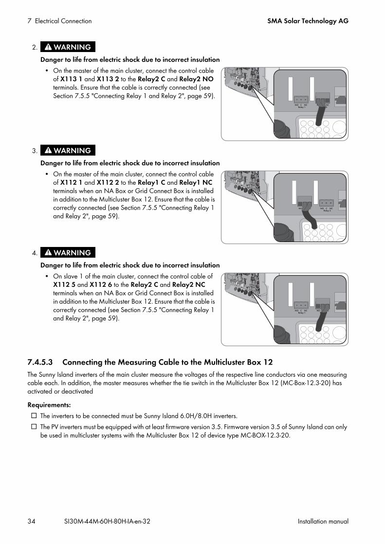
• On the master of the main cluster, connect the control cable of X113 1 and X113 2 to the Relay2 C and Relay2 NO terminals. Ensure that the cable is correctly connected (see Section 7.5.5 "Connecting Relay 1 and Relay 2", page 59).
3.Danger to life from electric shock due to incorrect insulation
• On the master of the main cluster, connect the control cable of X112 1 and X112 2 to the Relay1 C and Relay1 NC terminals when an NA Box or Grid Connect Box is installed in addition to the Multicluster Box 12. Ensure that the cable is correctly connected (see Section 7.5.5 "Connecting Relay 1 and Relay 2", page 59).
4.Danger to life from electric shock due to incorrect insulation
• On slave 1 of the main cluster, connect the control cable of X112 5 and X112 6 to the Relay2 C and Relay2 NC terminals when an NA Box or Grid Connect Box is installed in addition to the Multicluster Box 12. Ensure that the cable is correctly connected (see Section 7.5.5 "Connecting Relay 1 and Relay 2", page 59).

SMA Solar Technology AG 7 Electrical Connection
Installation manual SI30M-44M-60H-80H-IA-en-32 35
Procedure:1. On every Sunny Island of the main cluster, connect the measuring
cable for voltage monitoring of the Multicluster Box 12 to the ExtVtg terminal. Ensure that the cable is correctly connected (see Section 7.5.7 "Connecting ExtVtg", page 61):• On the master, connect the X112 3 and X112 4 conductors
to ExtVtg.• On slave 1, connect the X112 7 and X112 8 insulated
conductors to ExtVtg.• On slave 2, connect the X112 9 and X112 10 insulated
conductors to ExtVtg.2. At the master, connect the AC contactor monitoring. Ensure that
the cable is correctly connected (see Section 7.5.6 "Connecting BatVtgOut, DigIn, BatTMP and BatCur", page 60):• Connect BatVtgOut − with DigIn − within the master.• Connect the insulated conductor from X113 3 to
BatVtgOut+.• Connect the insulated conductor from X113 4 to DigIn+.
7.4.6 Connecting the Generator in an Off-Grid SystemIn single systems and single-cluster systems, connect a generator to connection AC2 of the Sunny Island inverter. For a multicluster system, connect the generator directly to the Multicluster Box (see the Multicluster Box documentation).
Requirements: A separate cable must be laid for each Sunny Island from the AC distribution board or directly from the generator. In single-phase parallel single-cluster systems, the cable lengths and conductor cross-sections from each Sunny Island
to the AC distribution board or directly to the generator must be configured in the same way. In a three-phase system, L1 must be assigned to the master, L2 to slave 1, and L3 to slave 2.
Procedure:• Connect the power cable to the AC2 Gen/Grid terminal on the
Sunny Island. Connect the neutral conductor to terminal N and ensure that the cable is correctly connected (see Section 7.5.2 "Connecting the AC Power Cable", page 56).
Danger to life from electric shock due to incorrect connection of the neutral conductorConnecting the neutral conductor incorrectly can cause failure of the protective functions in the system. This can result in death or serious injury.
• Connect the neutral conductor to terminal AC2 Gen/Grid N.
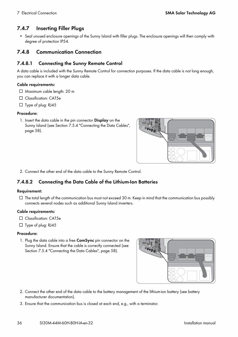
7 Electrical Connection SMA Solar Technology AG
36 SI30M-44M-60H-80H-IA-en-32 Installation manual
7.4.7 Inserting Filler Plugs• Seal unused enclosure openings of the Sunny Island with filler plugs. The enclosure openings will then comply with
degree of protection IP54.
7.4.8 Communication Connection7.4.8.1 Connecting the Sunny Remote ControlA data cable is included with the Sunny Remote Control for connection purposes. If the data cable is not long enough, you can replace it with a longer data cable.Cable requirements: Maximum cable length: 20 m Classification: CAT5e Type of plug: RJ45
Procedure:1. Insert the data cable in the pin connector Display on the
Sunny Island (see Section 7.5.4 "Connecting the Data Cables", page 58).
2. Connect the other end of the data cable to the Sunny Remote Control.
7.4.8.2 Connecting the Data Cable of the Lithium-Ion BatteriesRequirement: The total length of the communication bus must not exceed 30 m. Keep in mind that the communication bus possibly
connects several nodes such as additional Sunny Island inverters.Cable requirements: Classification: CAT5e Type of plug: RJ45
Procedure:1. Plug the data cable into a free ComSync pin connector on the
Sunny Island. Ensure that the cable is correctly connected (see Section 7.5.4 "Connecting the Data Cables", page 58).
2. Connect the other end of the data cable to the battery management of the lithium-ion battery (see battery manufacturer documentation).
3. Ensure that the communication bus is closed at each end, e.g., with a terminator.

SMA Solar Technology AG 7 Electrical Connection
Installation manual SI30M-44M-60H-80H-IA-en-32 37
7.4.8.3 Connecting the Communication Product via SpeedwireRequirement: A Speedwire data module for Sunny Island must be installed (see the installation manual of the SMA
Speedwire/Webconnect data module).Cable requirements: Cable length between two nodes:
– Maximum 50 m with patch cable– Maximum 100 m with installation cable
Cross-section: minimum 2 x 2 x 0.22 mm² or minimum 2 x 2 x AWG 24 Cable type: 100BaseTx, CAT5 with shielding S-UTP, F-UTP or higher Type of plug: RJ45
Procedure:1. On the Sunny Island, insert the data cable into the pin connector
of the Speedwire data module (for electrical connection, see the installation manual of the Speedwire data module Sunny Island).
2. Connect the other end of the data cable to the router or network switch.

7 Electrical Connection SMA Solar Technology AG
38 SI30M-44M-60H-80H-IA-en-32 Installation manual
7.4.8.4 Connecting the Data Cable for the Internal Communication of the ClusterIn a cluster, the Sunny Island inverters communicate via a black data cable.
Figure 11: Internal communication cabling
Requirements: The total length of the communication bus must not exceed 30 m. Keep in mind that the communication bus possibly
connects several nodes such as other Sunny Island Charger devices.Procedure:
1. Plug the data cable into a free ComSync pin connector on the Sunny Island. Ensure that the cable is correctly connected (see Section 7.5.4 "Connecting the Data Cables", page 58).
2. Ensure that the communication bus is closed at each end, e.g., with a terminator.
NO C NCRelay 1
NO C NCRelay 2
NO C NCRelay 1
NO C NCRelay 2
NO C NCRelay 1
NO C NCRelay 2
NO C NCRelay 1
NO C NCRelay 2
NO C NCRelay 1
NO C NCRelay 2
MASTER
MASTER SLAVE 1
SLAVE 1 SLAVE 2

SMA Solar Technology AG 7 Electrical Connection
Installation manual SI30M-44M-60H-80H-IA-en-32 39
7.4.8.5 Connecting the Data Cable of the Sunny Island Charger 50 Charge Controller
A maximum of four Sunny Island Charger 50 devices can be connected per cluster (see the quick reference guide “Off-Grid Systems”).Requirements: The total length of the communication bus must not exceed 30 m.
Cable requirements: Classification: CAT5e Type of plug: RJ45
Procedure:1. Plug the data cable into a free ComSync pin connector on the
Sunny Island. Ensure that the cable is correctly connected (see Section 7.5.4 "Connecting the Data Cables", page 58).
2. Connect the other end of the data cable to one Sunny Island Charger 50 and further Sunny Island Charger 50 devices to one another (see documentation for the Sunny Island Charger 50 charge controller).
3. Ensure that the communication bus is closed at each end, e.g., with a terminator.
7.4.8.6 Connecting the Data Cable of the Multicluster BoxFor a multicluster system, the Multicluster Box communicates with the master of the main cluster via a black data cable (see Multicluster Box documentation). The black data cable is part of the scope of delivery of the Multicluster Box.Requirements: The total length of the communication bus must not exceed 30 m. Keep in mind that the communication bus connects
several nodes such as additional Sunny Island inverters.Cable requirements: Classification: CAT5e Type of plug: RJ45
Procedure:1. Plug the data cable into a free ComSync pin connector on a
Sunny Island of the main cluster. Ensure that the cable is correctly connected (see Section 7.5.4 "Connecting the Data Cables", page 58).
2. Connect the other end of the data cable to the Multicluster Box (see Multicluster Box documentation).3. Ensure that the communication bus is closed at each end, e.g., with a terminator.

7 Electrical Connection SMA Solar Technology AG
40 SI30M-44M-60H-80H-IA-en-32 Installation manual
7.4.8.7 Connecting Control and Measuring Cables of the Multicluster BoxFor a multicluster system, the Multicluster Box communicates control and measuring data with the three Sunny Island inverters of the main cluster via three red data cables (see Multicluster Box documentation). The red data cables are part of the scope of delivery of the Multicluster Box.Procedure:
• Plug the red data cables into the pin connector BackupVtgCur on the Sunny Island units of the main cluster (see Section 7.5.4 "Connecting the Data Cables", page 58). Observe the following assignment:• Connect the master with the Mstr./L1 connection of the
Multicluster Box.• Connect slave 1 with the Slv1./L2 connection of the
Multicluster Box.• Connect slave 2 with the Slv2./L3 connection of the
Multicluster Box.
7.4.8.8 Connecting the Cable of the Multicluster CommunicationIn a multicluster system, the masters of the various clusters communicate with each other (see Multicluster Box documentation). An SI-SYSCAN.BGx communication interface must be installed in each master for Multicluster communication. This communication is not necessary for a multicluster system with one cluster. If the Sunny Island was ordered with the “Communication in multicluster systems” order option, SI-SYSCAN.BGx is installed in each master.
Figure 12: Design of the SI-SYSCAN.BGx
Cable requirements: Classification: CAT5e Maximum cable length: 30 m
Position DesignationA Mounting holeB Type labelC SysCanIn pin connectorD SysCanOut pin connector
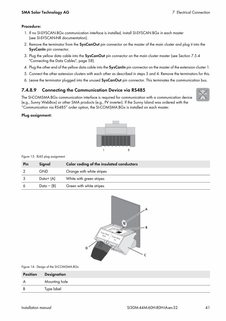
SMA Solar Technology AG 7 Electrical Connection
Installation manual SI30M-44M-60H-80H-IA-en-32 41
Procedure:1. If no SI-SYSCAN.BGx communication interface is installed, install SI-SYSCAN.BGx in each master
(see SI-SYSCAN-NR documentation).2. Remove the terminator from the SysCanOut pin connector on the master of the main cluster and plug it into the
SysCanIn pin connector.3. Plug the yellow data cable into the SysCanOut pin connector on the main cluster master (see Section 7.5.4
"Connecting the Data Cables", page 58).4. Plug the other end of the yellow data cable into the SysCanIn pin connector on the master of the extension cluster 1.5. Connect the other extension clusters with each other as described in steps 3 and 4. Remove the terminators for this.6. Leave the terminator plugged into the unused SysCanOut pin connector. This terminates the communication bus.
7.4.8.9 Connecting the Communication Device via RS485The SI-COMSMA.BGx communication interface is required for communication with a communication device (e.g., Sunny WebBox) or other SMA products (e.g., PV inverter). If the Sunny Island was ordered with the “Communication via RS485” order option, the SI-COMSMA.BGx is installed on each master.Plug assignment:
Figure 13: RJ45 plug assignment
Figure 14: Design of the SI-COMSMA.BGx
Pin Signal Color coding of the insulated conductors2 GND Orange with white stripes3 Data+ (A) White with green stripes6 Data − (B) Green with white stripes
Position DesignationA Mounting holeB Type label

7 Electrical Connection SMA Solar Technology AG
42 SI30M-44M-60H-80H-IA-en-32 Installation manual
Cable requirements: Classification: CAT5e Maximum cable length: 1,200 m
Procedure:1. If an SI-COMSMA.BGx is not installed in the Sunny Island, install an SI-COMSMA.BGx in the Sunny Island (see
SI-COMSMA-NR mounting instructions):• In single systems, install an SI-COMSMA.BGx in the Sunny Island.• In a single-cluster system, install an SI-COMSMA.BGx in the master.• In a multicluster system, install an SI-COMSMA.BGx in each master.
2. Connect the white data cable with open conductors to the communication device (see installation manual of the communication device).
3. Plug the white data cable into the ComSmaIn pin connector on the Sunny Island (see Section 7.5.4 "Connecting the Data Cables", page 58).
4. In a single-cluster system, plug the white data cable into the ComSmaIn pin connector on the master (see Section 7.5.4 "Connecting the Data Cables", page 58).
5. In a multicluster system, connect the masters to each other:• Remove the terminator from the ComSmaOut pin connector on the master of the main cluster.• Plug the gray data cable into the ComSmaOut pin connector on the master of the main cluster.• Plug the gray data cable into the ComSmaIn pin connector on the master of the extension cluster 1.• Connect the other extension clusters with each other as described.
6. Leave the terminator plugged into the unused ComSmaOut pin connector. This terminates the communication bus.
7.4.9 Connecting the Battery Temperature SensorWith lead-acid batteries, the battery management of the Sunny Island inverter must record the temperature of the connected battery.
C ComSmaIn pin connectorD ComSmaOut pin connector
Battery temperature sensor in a clusterOnly the master measures the battery temperature in a cluster.
• Connect the battery temperature sensor only to the master.
Position Designation
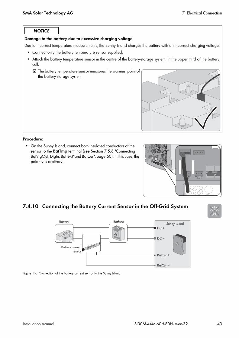
SMA Solar Technology AG 7 Electrical Connection
Installation manual SI30M-44M-60H-80H-IA-en-32 43
Procedure:• On the Sunny Island, connect both insulated conductors of the
sensor to the BatTmp terminal (see Section 7.5.6 "Connecting BatVtgOut, DigIn, BatTMP and BatCur", page 60). In this case, the polarity is arbitrary.
7.4.10 Connecting the Battery Current Sensor in the Off-Grid System
Figure 15: Connection of the battery current sensor to the Sunny Island.
Damage to the battery due to excessive charging voltageDue to incorrect temperature measurements, the Sunny Island charges the battery with an incorrect charging voltage.
• Connect only the battery temperature sensor supplied.• Attach the battery temperature sensor in the centre of the battery-storage system, in the upper third of the battery
cell. The battery temperature sensor measures the warmest point of
the battery-storage system.

7 Electrical Connection SMA Solar Technology AG
44 SI30M-44M-60H-80H-IA-en-32 Installation manual
Cable requirements: Copper wire Maximum cable length: 3 m Conductor cross-section: 0.2 mm² to 2.5 mm² A measuring cable with intrinsically safe current circuits must be used. For this purpose, “intrinsically safe” means
that the cable is double-insulated and that, in the event of a short circuit, the conductor melts but the insulation remains intact. In addition, the cable is not combustible.
Insulated conductors in the measuring cable must be twisted.Procedure:
1. Install the battery current sensor on the DC − power cable between the battery and BatFuse.2. Connect the BatCur+ insulated measuring conductor to the side
for connecting the BatFuse on the battery current sensor.
3. Connect the BatCur − insulated measuring conductor to the side for connecting the battery on the battery current sensor.
4. On the Sunny Island, connect the insulated conductors to the terminals BatCur + and BatCur − . Ensure that the cable is correctly connected (see Section 7.5.6 "Connecting BatVtgOut, DigIn, BatTMP and BatCur", page 60).

SMA Solar Technology AG 7 Electrical Connection
Installation manual SI30M-44M-60H-80H-IA-en-32 45
7.4.11 Connecting the Control Cable for Autostart GeneratorsAutostart generators are started and stopped with a contact.
Figure 16: Connection of the generator control to the Sunny Island
Requirements: The technical requirements of the multifunction relay must be met (see Section 10 "Technical Data", page 101).
Cable requirements: Copper wire Conductor cross-section: 0.2 mm² to 2.5 mm²
Procedure:
2. Go to Section 8.1.5, page 71 and enter AutoGn in the table for configuration.
Generator control in a clusterSlaves control the generator less reliably than masters do.
• Connect the generator control preferably to the master.• If the off-grid system is a multicluster system, always connect the generator control to the master of the main
cluster.
1.Danger to life from electric shock due to incorrect insulation
• Connect the control cable on the Sunny Island to either multifunction relay Relay1 or Relay2 (see Section 7.5.5 "Connecting Relay 1 and Relay 2", page 59). Use the C and NO connections.
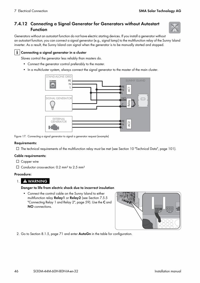
7 Electrical Connection SMA Solar Technology AG
46 SI30M-44M-60H-80H-IA-en-32 Installation manual
7.4.12 Connecting a Signal Generator for Generators without Autostart Function
Generators without an autostart function do not have electric starting devices. If you install a generator without an autostart function, you can connect a signal generator (e.g., signal lamp) to the multifunction relay of the Sunny Island inverter. As a result, the Sunny Island can signal when the generator is to be manually started and stopped.
Figure 17: Connecting a signal generator to signal a generator request (example)
Requirements: The technical requirements of the multifunction relay must be met (see Section 10 "Technical Data", page 101).
Cable requirements: Copper wire Conductor cross-section: 0.2 mm² to 2.5 mm²
Procedure:
2. Go to Section 8.1.5, page 71 and enter AutoGn in the table for configuration.
Connecting a signal generator in a clusterSlaves control the generator less reliably than masters do.
• Connect the generator control preferably to the master.• In a multicluster system, always connect the signal generator to the master of the main cluster.
1.Danger to life from electric shock due to incorrect insulation
• Connect the control cable on the Sunny Island to either multifunction relay Relay1 or Relay2 (see Section 7.5.5 "Connecting Relay 1 and Relay 2", page 59). Use the C and NO connections.
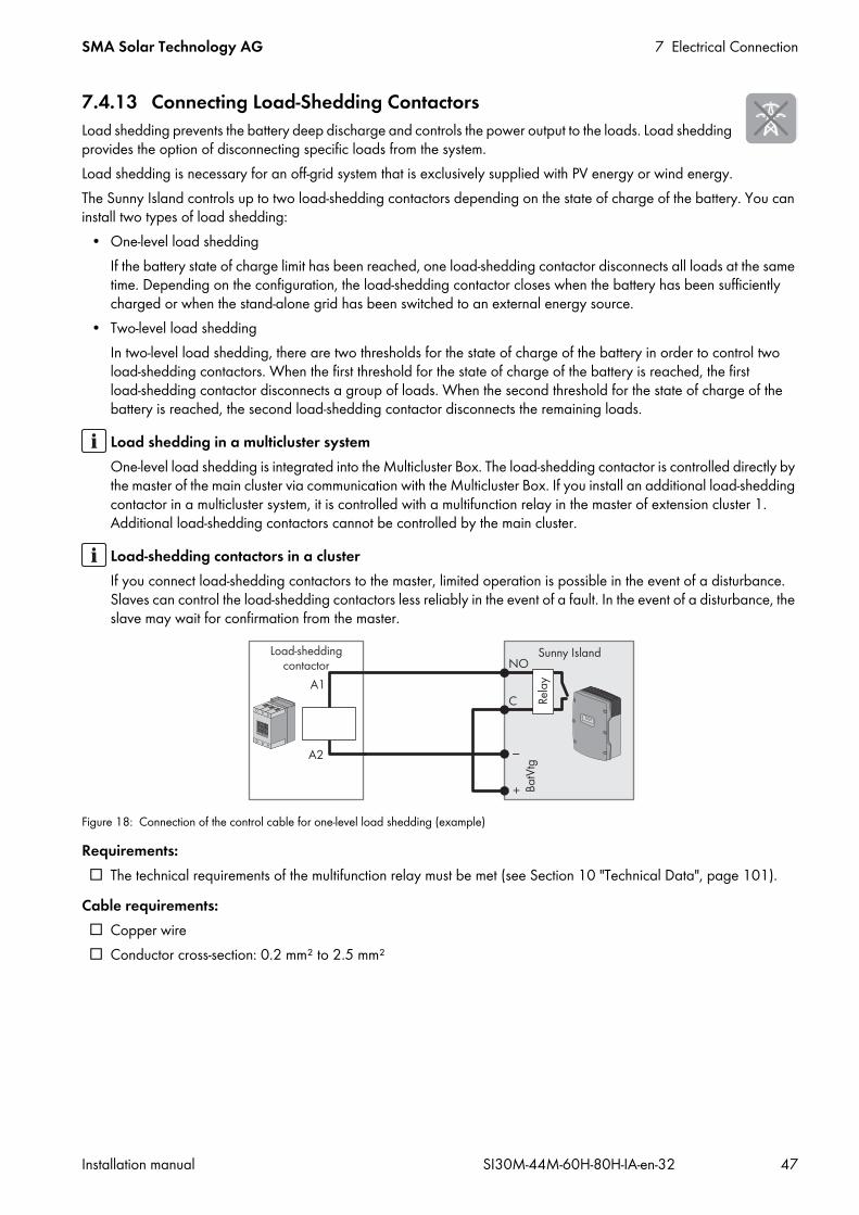
SMA Solar Technology AG 7 Electrical Connection
Installation manual SI30M-44M-60H-80H-IA-en-32 47
7.4.13 Connecting Load-Shedding ContactorsLoad shedding prevents the battery deep discharge and controls the power output to the loads. Load shedding provides the option of disconnecting specific loads from the system.Load shedding is necessary for an off-grid system that is exclusively supplied with PV energy or wind energy.The Sunny Island controls up to two load-shedding contactors depending on the state of charge of the battery. You can install two types of load shedding:
• One-level load sheddingIf the battery state of charge limit has been reached, one load-shedding contactor disconnects all loads at the same time. Depending on the configuration, the load-shedding contactor closes when the battery has been sufficiently charged or when the stand-alone grid has been switched to an external energy source.
• Two-level load sheddingIn two-level load shedding, there are two thresholds for the state of charge of the battery in order to control two load-shedding contactors. When the first threshold for the state of charge of the battery is reached, the first load-shedding contactor disconnects a group of loads. When the second threshold for the state of charge of the battery is reached, the second load-shedding contactor disconnects the remaining loads.
Figure 18: Connection of the control cable for one-level load shedding (example)
Requirements: The technical requirements of the multifunction relay must be met (see Section 10 "Technical Data", page 101).
Cable requirements: Copper wire Conductor cross-section: 0.2 mm² to 2.5 mm²
Load shedding in a multicluster systemOne-level load shedding is integrated into the Multicluster Box. The load-shedding contactor is controlled directly by the master of the main cluster via communication with the Multicluster Box. If you install an additional load-shedding contactor in a multicluster system, it is controlled with a multifunction relay in the master of extension cluster 1. Additional load-shedding contactors cannot be controlled by the main cluster.
Load-shedding contactors in a clusterIf you connect load-shedding contactors to the master, limited operation is possible in the event of a disturbance. Slaves can control the load-shedding contactors less reliably in the event of a fault. In the event of a disturbance, the slave may wait for confirmation from the master.

7 Electrical Connection SMA Solar Technology AG
48 SI30M-44M-60H-80H-IA-en-32 Installation manual
Procedure:1. Ensure that the load-shedding contactor only disconnects loads from the system. This ensures that the battery can be
recharged from AC sources in the system.2. Connect the insulated conductor for coil connection A1 of the load-shedding contactor to terminal Relay1 NO
(see Section 7.5.5 "Connecting Relay 1 and Relay 2", page 59).3. Connect the insulated conductor for coil connection A2 to terminal BatVtgOut − (see Section 7.5.6 "Connecting
BatVtgOut, DigIn, BatTMP and BatCur", page 60).4. Connect terminal BatVtgOut + to terminal Relay1 C. Use the same conductor cross-section as that of the cable for
the load-shedding contactor.5. Go to Section 8.1.5, page 71 and enter the following values in the table for configuration 1.
6. Repeat steps 1 to 5 for two-level load shedding. Connect the second load-shedding contactor to an unused multifunction relay.
7.4.14 Connecting the Time Control for External ProcessesThe Sunny Island has two timers for time-dependent control of external processes. For each timer, you can set the starting day and time that the multifunction relay is to be switched once, daily or weekly.Requirements: The technical requirements of the multifunction relay must be met (see Section 10 "Technical Data", page 101).
Cable requirements: Copper wire Conductor cross-section: 0.2 mm² to 2.5 mm²
Procedure:
2. Go to Section 8.1.5, page 71 and enter the value TM1 for timer 1 or the value TM2 for timer 2 in the table for configuration.
Value ExplanationAutoLodExt Setting for one-level load shedding. When the Sunny Island switches to an external energy
source, load shedding is stopped and the loads are supplied by the external energy source. The battery is only charged with the excess energy.
AutoLod1Soc Setting for one-level load shedding or the first level of two-level load shedding. Load shedding is only stopped when the battery has been sufficiently charged.
AutoLod2Soc Setting for the second level of two-level load shedding. Load shedding is only stopped when the battery has been sufficiently charged.
MccAutoLod Setting for additional one-level load shedding in a multicluster system. Load shedding is only stopped when the batteries of the extension cluster have been sufficiently charged.
1.Danger to life from electric shock due to incorrect insulation
• Connect the control cable on the Sunny Island to either multifunction relay Relay1 or Relay2 (see Section 7.5.5 "Connecting Relay 1 and Relay 2", page 59). Use the C and NO connections.
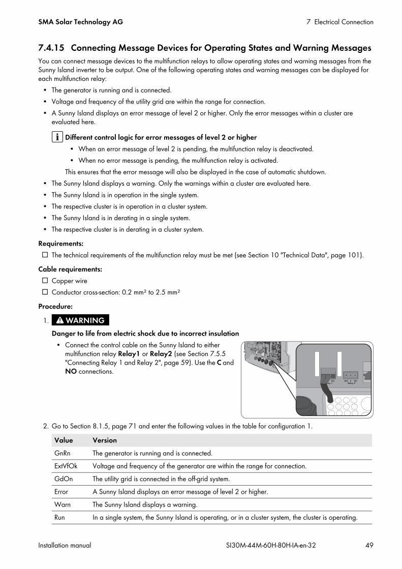
SMA Solar Technology AG 7 Electrical Connection
Installation manual SI30M-44M-60H-80H-IA-en-32 49
7.4.15 Connecting Message Devices for Operating States and Warning MessagesYou can connect message devices to the multifunction relays to allow operating states and warning messages from the Sunny Island inverter to be output. One of the following operating states and warning messages can be displayed for each multifunction relay:
• The generator is running and is connected.• Voltage and frequency of the utility grid are within the range for connection.• A Sunny Island displays an error message of level 2 or higher. Only the error messages within a cluster are
evaluated here.
• The Sunny Island displays a warning. Only the warnings within a cluster are evaluated here.• The Sunny Island is in operation in the single system.• The respective cluster is in operation in a cluster system.• The Sunny Island is in derating in a single system.• The respective cluster is in derating in a cluster system.
Requirements: The technical requirements of the multifunction relay must be met (see Section 10 "Technical Data", page 101).
Cable requirements: Copper wire Conductor cross-section: 0.2 mm² to 2.5 mm²
Procedure:
2. Go to Section 8.1.5, page 71 and enter the following values in the table for configuration 1.
Different control logic for error messages of level 2 or higher• When an error message of level 2 is pending, the multifunction relay is deactivated.• When no error message is pending, the multifunction relay is activated.
This ensures that the error message will also be displayed in the case of automatic shutdown.
1.Danger to life from electric shock due to incorrect insulation
• Connect the control cable on the Sunny Island to either multifunction relay Relay1 or Relay2 (see Section 7.5.5 "Connecting Relay 1 and Relay 2", page 59). Use the C and NO connections.
Value VersionGnRn The generator is running and is connected.ExtVfOk Voltage and frequency of the generator are within the range for connection.GdOn The utility grid is connected in the off-grid system.Error A Sunny Island displays an error message of level 2 or higher.Warn The Sunny Island displays a warning.Run In a single system, the Sunny Island is operating, or in a cluster system, the cluster is operating.

7 Electrical Connection SMA Solar Technology AG
50 SI30M-44M-60H-80H-IA-en-32 Installation manual
7.4.16 Connecting the Battery Room FanIf the charging current leads to the emission of gases from the battery, the battery room fan is switched on by the Sunny Island for at least one hour.Requirements: The technical requirements of the multifunction relay must be met (see Section 10 "Technical Data", page 101).
Cable requirements: Copper wire Conductor cross-section: 0.2 mm² to 2.5 mm²
Procedure:The battery management of the Sunny Island inverter is able to control one battery room fan for each battery. The following options result for the connection:
• Control a separate battery room fan for each battery.• Control one battery room fan for all batteries.
This is only an option with multicluster systems.
Controlling a separate battery room fan for each battery1. Ensure that the battery room is sufficiently ventilated in the case of a malfunction of the multifunction relay.
Overload In a single system, a Sunny Island is in derating, or in a cluster system, the cluster is in derating.
2.Danger to life from electric shock due to incorrect insulation
• With single systems or single-cluster systems:• Connect the battery room fan to a multifunction relay (see
Section 7.5.5 "Connecting Relay 1 and Relay 2", page 59).
• Go to Section 8.1.5, page 71 and enter BatFan in the table for configuration.• With a multicluster system:
• In each cluster, connect one battery room fan on one Sunny Island to any multifunction relay (see Section 7.5.5 "Connecting Relay 1 and Relay 2", page 59).
• Go to Section 8.1.5, page 71 and enter BatFan in the table for configuration.
Value Version

SMA Solar Technology AG 7 Electrical Connection
Installation manual SI30M-44M-60H-80H-IA-en-32 51
Controlling one battery room fan for all batteries1. Ensure that the battery room is sufficiently ventilated in the case of a malfunction of the multifunction relay.
3. Go to Section 8.1.5, page 71 and enter MccBatFan in the table for configuration.
7.4.17 Connecting the Electrolyte Pump for the BatteryThe Sunny Island controls the electrolyte pump for the battery as follows:
• The Sunny Island switches on the electrolyte pump at least once a day.• The Sunny Island switches on the electrolyte pump a maximum of nine times each day.• When the battery has been charged to 10% of its rated capacity, the Sunny Island switches the electrolyte pump on
for five minutes.Requirements: The technical requirements of the multifunction relay must be met (see Section 10 "Technical Data", page 101).
Cable requirements: Copper wire Conductor cross-section: 0.2 mm² to 2.5 mm²
Procedure:
2. For a multicluster system, repeat step 1 for every cluster.3. Go to Section 8.1.5, page 71 and enter AcdCir in the table for configuration.
2.Danger to life from electric shock due to incorrect insulation
• Connect the battery room fan to one multifunction relay on a Sunny Island of the main cluster (see Section 7.5.5 "Connecting Relay 1 and Relay 2", page 59).
1.Danger to life from electric shock due to incorrect insulation
1. On the Sunny Island, connect the control cable of the acid circulation to a multifunction relay (see Section 7.5.5 "Connecting Relay 1 and Relay 2", page 59).

7 Electrical Connection SMA Solar Technology AG
52 SI30M-44M-60H-80H-IA-en-32 Installation manual
7.4.18 Connecting the Control Cable for the Use of Excess Energy in an Off-Grid System
If the battery can no longer take up excess energy in an off-grid system, the power output of the AC sources in the stand-alone grid is limited by the Sunny Island. This means that the excess energy is not used. The Sunny Island allows for the use of excess energy by means of a multifunction relay.During the constant voltage phase, a multifunction relay is activated and thus controls additional loads that can put any excess energy to good use. As a result of the utilization of excess energy, the Sunny Island has to limit the power output of the AC sources in the stand-alone grid to a lesser extent.
Requirements: The technical requirements of the multifunction relay must be met (see Section 10 "Technical Data", page 101).
Cable requirements: Copper wire Conductor cross-section: 0.2 mm² to 2.5 mm²
Procedure:
2. Enter the function of the multifunction relay used in the configuration table (see Section 8.1.5 "Setting the Functions of the Multifunction Relays", page 71). Note the ExtPwrDer value.
3. After performing basic system configuration, adjust the multifunction relay (see Section 8.1.5, page 71) and function (see Section 8.3.6, page 89).
Example: Utilization of excess energyThe energy source of an off-grid system is PV energy. On days with high solar irradiation and low power consumption, the battery cannot take up all of the PV energy during the constant voltage phase. In order to utilize the excess energy, the Sunny Island activates the control of a pump that pumps water into a container for subsequent use.
1.Danger to life from electric shock due to incorrect insulation
• On the Sunny Island, connect the control cable for the utilization of excess energy to the multifunction relay (see Section 7.5.5 "Connecting Relay 1 and Relay 2", page 59).

SMA Solar Technology AG 7 Electrical Connection
Installation manual SI30M-44M-60H-80H-IA-en-32 53
7.4.19 Connecting the Signal Cable of the External Generator RequestAn external control signal can transmit a generator request to the generator management. If you have configured the generator management for the external generator request, the generator management starts the generator if there is a high level present. The generator management stops the generator if there is a low level. As a result, all generator run times are complied with.
Figure 19: Connection of the control cable of an external generator request (example).
Requirements: The technical requirements of the digital input must be complied with (see Section 10 "Technical Data", page 101).
Cable requirements: Copper wire Conductor cross-section: 0.2 mm² to 2.5 mm²
Procedure:1. On the Sunny Island, connect one insulated conductor of the control cable to terminal BatVtgOut+
(see Section 7.5.6 "Connecting BatVtgOut, DigIn, BatTMP and BatCur", page 60).2. Connect one insulated conductor of the control cable to terminal DigIn +.3. Connect terminal BatVtgOut– to terminal DigIn –. Use the same conductor as in the control cable.
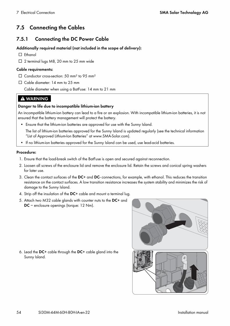
7 Electrical Connection SMA Solar Technology AG
54 SI30M-44M-60H-80H-IA-en-32 Installation manual
7.5 Connecting the Cables7.5.1 Connecting the DC Power CableAdditionally required material (not included in the scope of delivery): Ethanol 2 terminal lugs M8, 20 mm to 25 mm wide
Cable requirements: Conductor cross-section: 50 mm² to 95 mm² Cable diameter: 14 mm to 25 mm
Cable diameter when using a BatFuse: 14 mm to 21 mm
Procedure:1. Ensure that the load-break switch of the BatFuse is open and secured against reconnection.2. Loosen all screws of the enclosure lid and remove the enclosure lid. Retain the screws and conical spring washers
for later use.3. Clean the contact surfaces of the DC+ and DC- connections, for example, with ethanol. This reduces the transition
resistance on the contact surfaces. A low transition resistance increases the system stability and minimizes the risk of damage to the Sunny Island.
4. Strip off the insulation of the DC+ cable and mount a terminal lug.5. Attach two M32 cable glands with counter nuts to the DC+ and
DC − enclosure openings (torque: 12 Nm).
6. Lead the DC+ cable through the DC+ cable gland into the Sunny Island.
Danger to life due to incompatible lithium-ion batteryAn incompatible lithium-ion battery can lead to a fire or an explosion. With incompatible lithium-ion batteries, it is not ensured that the battery management will protect the battery.
• Ensure that the lithium-ion batteries are approved for use with the Sunny Island. The list of lithium-ion batteries approved for the Sunny Island is updated regularly (see the technical information “List of Approved Lithium-Ion Batteries” at www.SMA-Solar.com).
• If no lithium-ion batteries approved for the Sunny Island can be used, use lead-acid batteries.

SMA Solar Technology AG 7 Electrical Connection
Installation manual SI30M-44M-60H-80H-IA-en-32 55
8. Strip off the insulation of the DC– cable and mount a terminal lug.9. Lead the DC– cable through the DC– cable gland into the
Sunny Island.
10. Route the DC– cable on the side of the protective cover marked with a – symbol.
7.Damage to Sunny Island inverter due to reverse polarity or incorrect terminal lug selectionIf the DC cables are swapped, high currents will flow after the load-break switch has closed and these can damage the Sunny Island.
• Route the DC+ cable on the side of the protective cover marked with a + symbol.• Use an Allen key (AF 5) to fasten the DC+ cable to the
DC+ connection with an M8x20 screw (torque: 12 Nm). Be sure to adhere to the following screw assembly: screw head | spring washer | fender washer | terminal lug | DC connection.
The entire contact surface of the fender washer is in contact with the terminal lug.

7 Electrical Connection SMA Solar Technology AG
56 SI30M-44M-60H-80H-IA-en-32 Installation manual
11. Use an Allen key (AF 5) to fasten the DC– cable to the DC– connection with an M8x20 screw (torque: 12 Nm). Be sure to adhere to the following screw assembly: screw head | spring washer | fender washer | terminal lug | DC connection.
The entire contact surface of the fender washer is in contact with the terminal lug.
12. Tighten the swivel nuts of the cable glands (torque 4.5 Nm).
7.5.2 Connecting the AC Power CableAlways proceed as follows to connect the power cables.Cable requirements: Copper wire Conductor cross-section: maximum 16 mm² Cable diameter: 9 mm to 18 mm
Danger to life from electric shock due to incorrect connection of the neutral conductorThe neutral conductor of the external energy source is firmly connected to the neutral conductor of the Sunny Island inverter on connection AC2 Gen/Grid N. Upon disconnection of the external energy source, the Sunny Island only disconnects the line conductor on connection AC2 Gen/Grid N. The Sunny Island disconnects all poles from the external energy source on connection AC2 Gen/Grid NTT. If the neutral conductor is incorrectly connected on connection AC2, the protective functions in the system can fail. This can result in death or serious injury.
• Always connect the neutral conductor to the connection AC2 Gen/Grid NTT in the SMA Flexible Storage System.• Always connect the neutral conductor to the connection AC2 Gen/Grid NTT in the SMA Flexible Storage System
with battery-backup function.• Always connect the neutral conductor of the generator to the connection AC2 Gen/Grid N in off-grid systems.• Always connect the neutral conductor to the connection AC2 Gen/Grid N in the multicluster system with
Multicluster Box 12. (MC-Box-12.3-20).

SMA Solar Technology AG 7 Electrical Connection
Installation manual SI30M-44M-60H-80H-IA-en-32 57
Procedure:1. Push the levers of the AC1 or AC2 terminal upward.2. When connecting the cable to connection AC1, attach the M25
cable gland to the AC1 enclosure opening using the counter nut (torque: 7 Nm).
3. When connecting the cable to connection AC2, attach the M25 cable gland to the AC2 enclosure opening using the counter nut (torque: 7 Nm).
4. Remove the cable jacket and strip off 13 mm of the the insulation of all conductors.5. Lead the cable through the cable gland into the Sunny Island.6. Connect the insulated conductors to the terminals AC1 Loads/SunnyBoys or AC2 Gen/Grid:
• Insert the neutral conductor as far as it will go into terminal N or NTT and push the lever down.• Insert the line conductor as far as it will go into terminal L and push the lever down.• Insert the grounding conductor as far as it will go into terminal PE and push the lever down.
7. Tighten the swivel nut of the cable gland (torque: 4 Nm).
7.5.3 Connecting the Grounding ConductorThe Sunny Island must be connected to the ground potential via a grounding conductor on connection AC1 or AC2. The conductor cross-section of the grounding conductor must be at least 10 mm². If the conductor cross-section is smaller, an additional grounding conductor must connect the Sunny Island with the ground potential.Additional grounding is fulfilled if the Sunny Island is already grounded due to the grounded battery (see Section 7.3 "Connecting the Grounding Conductor in Systems with a Grounded Battery", page 27).Cable requirements: Conductor cross-section:
– Cross-section of the connected line conductor or larger– Maximum 16 mm²
Cable diameter: 7 mm to 14 mm
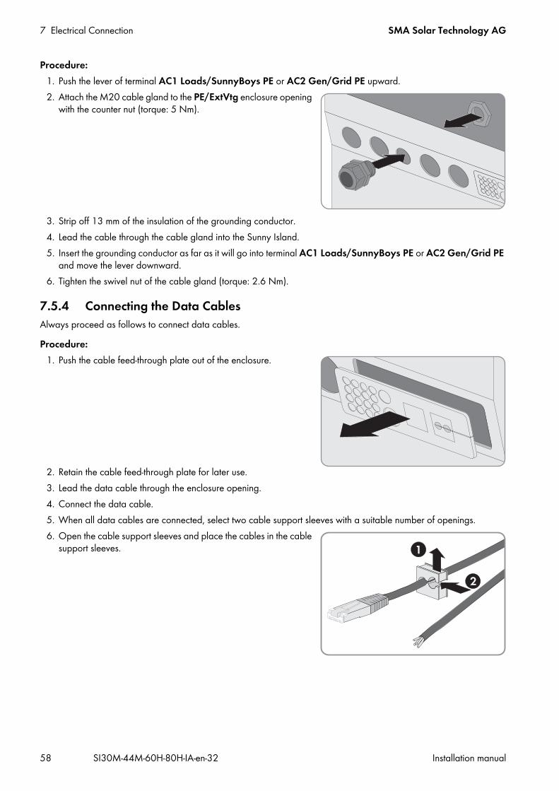
7 Electrical Connection SMA Solar Technology AG
58 SI30M-44M-60H-80H-IA-en-32 Installation manual
Procedure:1. Push the lever of terminal AC1 Loads/SunnyBoys PE or AC2 Gen/Grid PE upward.2. Attach the M20 cable gland to the PE/ExtVtg enclosure opening
with the counter nut (torque: 5 Nm).
3. Strip off 13 mm of the insulation of the grounding conductor.4. Lead the cable through the cable gland into the Sunny Island.5. Insert the grounding conductor as far as it will go into terminal AC1 Loads/SunnyBoys PE or AC2 Gen/Grid PE
and move the lever downward.6. Tighten the swivel nut of the cable gland (torque: 2.6 Nm).
7.5.4 Connecting the Data CablesAlways proceed as follows to connect data cables.Procedure:
1. Push the cable feed-through plate out of the enclosure.
2. Retain the cable feed-through plate for later use.3. Lead the data cable through the enclosure opening.4. Connect the data cable.5. When all data cables are connected, select two cable support sleeves with a suitable number of openings.6. Open the cable support sleeves and place the cables in the cable
support sleeves.

SMA Solar Technology AG 7 Electrical Connection
Installation manual SI30M-44M-60H-80H-IA-en-32 59
7. Open the cable feed-through plate and insert the cable support sleeves into the cable feed-through plate. Position the flat sides of each cable support sleeve on the flat side in the cable feed-through plate.
8. Hold the cables and push the cable feed-through plate to the enclosure opening of the cable feed-through plate.
9. Hook the cable feed-through plate into the enclosure opening of the cable feed-through plate and press into the enclosure opening.
7.5.5 Connecting Relay 1 and Relay 2If you are using a multifunction relay, always connect it as follows:
Additionally required material (not included in the scope of delivery): Suitable bootlace ferrules if using stranded wire
Requirement: The technical requirements of the multifunction relay must be met (see Section 10 "Technical Data", page 101). Copper wire Conductor cross-section: 0.2 mm² to 2.5 mm²
Procedure:1. Break through a suitable location in the cable feed-through plate with a sharp object.2. Strip off the insulation from the cable and press bootlace ferrules onto the insulated conductors.3. Lead the cable through the hole in the cable feed-through plate into the Sunny Island.
Switching behavior of the slavesIn case of a fault, the multifunction relays of the slaves switch less reliably than the multifunction relays of the masters. In case of a fault, the slaves wait for the master to confirm the fault.
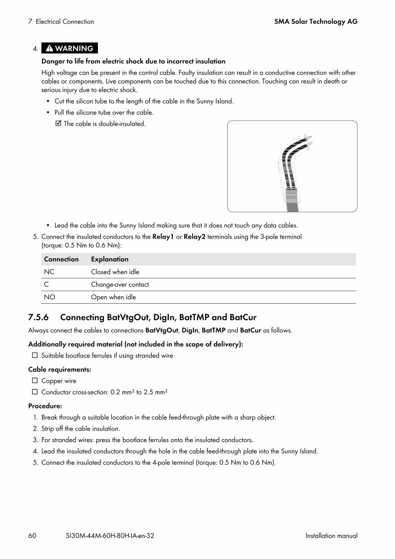
7 Electrical Connection SMA Solar Technology AG
60 SI30M-44M-60H-80H-IA-en-32 Installation manual
5. Connect the insulated conductors to the Relay1 or Relay2 terminals using the 3-pole terminal (torque: 0.5 Nm to 0.6 Nm):
7.5.6 Connecting BatVtgOut, DigIn, BatTMP and BatCurAlways connect the cables to connections BatVtgOut, DigIn, BatTMP and BatCur as follows.Additionally required material (not included in the scope of delivery): Suitable bootlace ferrules if using stranded wire
Cable requirements: Copper wire Conductor cross-section: 0.2 mm² to 2.5 mm²
Procedure:1. Break through a suitable location in the cable feed-through plate with a sharp object.2. Strip off the cable insulation.3. For stranded wires: press the bootlace ferrules onto the insulated conductors.4. Lead the insulated conductors through the hole in the cable feed-through plate into the Sunny Island.5. Connect the insulated conductors to the 4-pole terminal (torque: 0.5 Nm to 0.6 Nm).
4.Danger to life from electric shock due to incorrect insulationHigh voltage can be present in the control cable. Faulty insulation can result in a conductive connection with other cables or components. Live components can be touched due to this connection. Touching can result in death or serious injury due to electric shock.
• Cut the silicon tube to the length of the cable in the Sunny Island.• Pull the silicone tube over the cable.
The cable is double-insulated.
• Lead the cable into the Sunny Island making sure that it does not touch any data cables.
Connection ExplanationNC Closed when idleC Change-over contactNO Open when idle
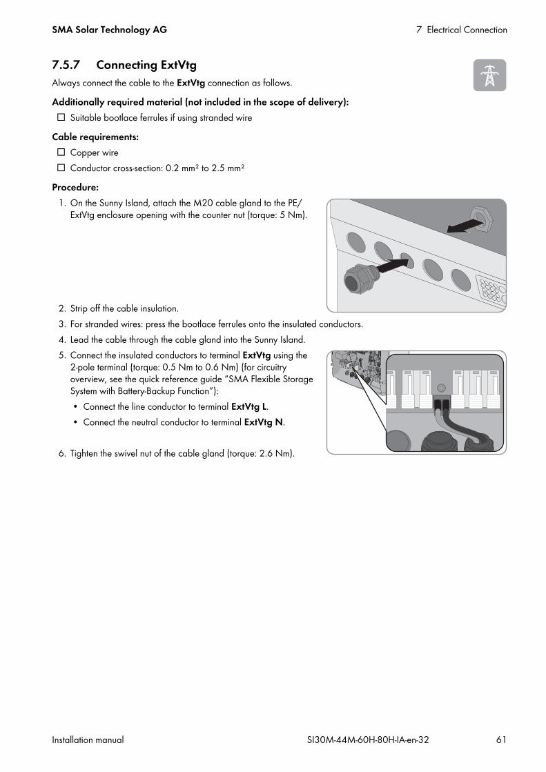
SMA Solar Technology AG 7 Electrical Connection
Installation manual SI30M-44M-60H-80H-IA-en-32 61
7.5.7 Connecting ExtVtgAlways connect the cable to the ExtVtg connection as follows.Additionally required material (not included in the scope of delivery): Suitable bootlace ferrules if using stranded wire
Cable requirements: Copper wire Conductor cross-section: 0.2 mm² to 2.5 mm²
Procedure:1. On the Sunny Island, attach the M20 cable gland to the PE/
ExtVtg enclosure opening with the counter nut (torque: 5 Nm).
2. Strip off the cable insulation.3. For stranded wires: press the bootlace ferrules onto the insulated conductors.4. Lead the cable through the cable gland into the Sunny Island.5. Connect the insulated conductors to terminal ExtVtg using the
2-pole terminal (torque: 0.5 Nm to 0.6 Nm) (for circuitry overview, see the quick reference guide “SMA Flexible Storage System with Battery-Backup Function”):• Connect the line conductor to terminal ExtVtg L.• Connect the neutral conductor to terminal ExtVtg N.
6. Tighten the swivel nut of the cable gland (torque: 2.6 Nm).

7 Electrical Connection SMA Solar Technology AG
62 SI30M-44M-60H-80H-IA-en-32 Installation manual
7.6 Checking the WiringEnsure that you carry out all tests relevant to the system and rectify all detected problems. Tip: Tests can be documented directly in the tables. Cross out all tests not applicable.Requirement: All Sunny Island inverters must be voltage-free (see the Sunny Island inverter operating manual).
Procedure:
Checking the grounding
Checking the additional groundingIf the battery is grounded, you must check the additional grounding on the Sunny Island.
Test point Test criterion OKEnclosure opening, PE/ExtVtg Enclosure opening is sealed with a filler plug or M20 cable gland.
The cable diameter of the cable must be 7 mm to 14 mm for an M20 cable gland.
Conductor cross-section of the grounding conductor at the AC1 and AC2 connections
If one grounding conductor is connected, the conductor cross-section must be at least 10 mm². If two grounding conductors are connected, the cross-section of each conductor must be at least 4 mm².
Grounding conductor connection to ground
The grounding conductor must be grounded, e.g., by connection to a grounding busbar or a foundation ground electrode.
With a TN system, neutral conductor and grounding conductor connection
Ensure by measuring that there is a conductive connection between the neutral conductor and the grounding conductor.
Grounding of the battery Ensure that the battery is not grounded unintentionally.If the battery has been grounded intentionally, ensure that the conductor cross-section is sufficient (see Section 7.3 "Connecting the Grounding Conductor in Systems with a Grounded Battery", page 27).
Test point Test criterion OKConductor cross-section for the additional grounding
The conductor cross-section must correspond to the grounding of the battery.
Connection of additional grounding Hexagon socket screw is screwed tight (torque: 4 Nm to 5.7 Nm). Grounding conductor connection to ground
The grounding conductors must be grounded, e.g., by connection to a grounding busbar or foundation ground electrode.

SMA Solar Technology AG 7 Electrical Connection
Installation manual SI30M-44M-60H-80H-IA-en-32 63
Checking the DC connection of the Sunny Island inverter
Checking connections AC1 and AC2 of the Sunny Island inverter
Test point Test criterion OKEnclosure opening for DC In the cable gland M32, the diameter of the DC power cable must
be 14 mm to 25 mm.
DC connection Terminal lugs are pressed on firmly. The bolted connection for fitting terminal lugs to the DC connection is assembled as follows: head of M8x20 screw | spring washer | fender washer | terminal lug | DC connection.
Terminal lugs are firmly fastened on the Sunny Island (torque: 12 Nm).
DC power cable The maximum length of cables from the battery via the BatFuse to the Sunny Island is 10 m.
The conductor cross-section meets the cable requirements of 50 mm² to 95 mm² (for the recommended conductor cross-section, see Section 7.4.1).
BatFuse Fuse links are matched to the Sunny Island.• SI3.0M-11: 80 A• SI4.4M-11: 100 A• SI6.0H-11: 160 A• SI8.0H-11: 200 A
The cables are attached to the BatFuse with the required torque (see BatFuse installation manual).
If installed, charge controllers and DC loads
All charge controllers and DC loads are installed in accordance with the manufacturer’s specifications.
If installed, battery current sensor The battery current sensor can be loaded with the maximum DC current (see technical data of the battery current sensor).
Test point Test criterion OKAC1 and AC2 enclosure openings All enclosure openings are sealed with M25 cable glands or filler
plugs.
For an M25 cable gland, the cable diameter must be 9 mm to 18 mm.
Connections AC1 and AC2 All contact areas are not insulated. All terminal levers are in the downward position. All cables are securely clamped.
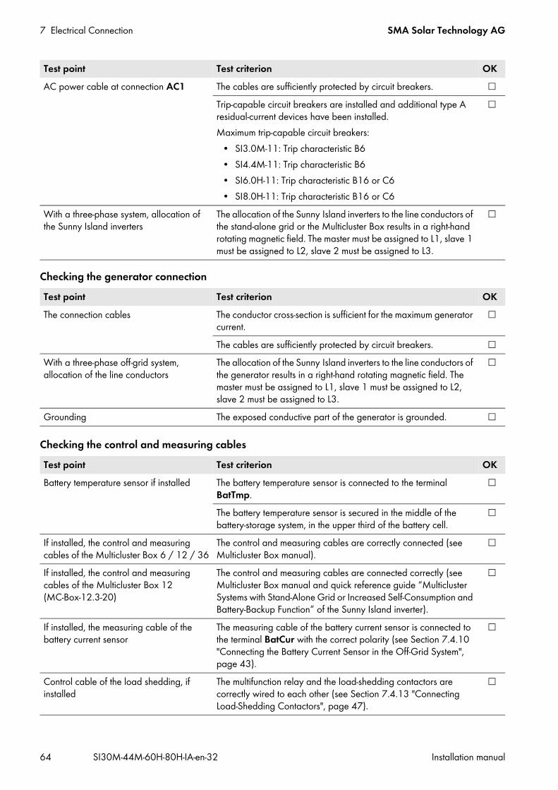
7 Electrical Connection SMA Solar Technology AG
64 SI30M-44M-60H-80H-IA-en-32 Installation manual
Checking the generator connection
Checking the control and measuring cables
AC power cable at connection AC1 The cables are sufficiently protected by circuit breakers. Trip-capable circuit breakers are installed and additional type A residual-current devices have been installed.Maximum trip-capable circuit breakers:
• SI3.0M-11: Trip characteristic B6• SI4.4M-11: Trip characteristic B6• SI6.0H-11: Trip characteristic B16 or C6• SI8.0H-11: Trip characteristic B16 or C6
With a three-phase system, allocation of the Sunny Island inverters
The allocation of the Sunny Island inverters to the line conductors of the stand-alone grid or the Multicluster Box results in a right-hand rotating magnetic field. The master must be assigned to L1, slave 1 must be assigned to L2, slave 2 must be assigned to L3.
Test point Test criterion OKThe connection cables The conductor cross-section is sufficient for the maximum generator
current.
The cables are sufficiently protected by circuit breakers. With a three-phase off-grid system, allocation of the line conductors
The allocation of the Sunny Island inverters to the line conductors of the generator results in a right-hand rotating magnetic field. The master must be assigned to L1, slave 1 must be assigned to L2, slave 2 must be assigned to L3.
Grounding The exposed conductive part of the generator is grounded.
Test point Test criterion OKBattery temperature sensor if installed The battery temperature sensor is connected to the terminal
BatTmp.
The battery temperature sensor is secured in the middle of the battery-storage system, in the upper third of the battery cell.
If installed, the control and measuring cables of the Multicluster Box 6 / 12 / 36
The control and measuring cables are correctly connected (see Multicluster Box manual).
If installed, the control and measuring cables of the Multicluster Box 12 (MC-Box-12.3-20)
The control and measuring cables are connected correctly (see Multicluster Box manual and quick reference guide “Multicluster Systems with Stand-Alone Grid or Increased Self-Consumption and Battery-Backup Function” of the Sunny Island inverter).
If installed, the measuring cable of the battery current sensor
The measuring cable of the battery current sensor is connected to the terminal BatCur with the correct polarity (see Section 7.4.10 "Connecting the Battery Current Sensor in the Off-Grid System", page 43).
Control cable of the load shedding, if installed
The multifunction relay and the load-shedding contactors are correctly wired to each other (see Section 7.4.13 "Connecting Load-Shedding Contactors", page 47).
Test point Test criterion OK
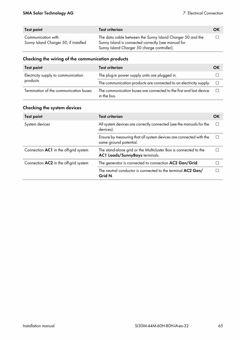
SMA Solar Technology AG 7 Electrical Connection
Installation manual SI30M-44M-60H-80H-IA-en-32 65
Checking the wiring of the communication products
Checking the system devices
Communication with Sunny Island Charger 50, if installed
The data cable between the Sunny Island Charger 50 and the Sunny Island is connected correctly (see manual for Sunny Island Charger 50 charge controller).
Test point Test criterion OKElectricity supply to communication products
The plug-in power supply units are plugged in. The communication products are connected to an electricity supply.
Termination of the communication buses The communication buses are connected to the first and last device in the bus.
Test point Test criterion OKSystem devices All system devices are correctly connected (see the manuals for the
devices).
Ensure by measuring that all system devices are connected with the same ground potential.
Connection AC1 in the off-grid system The stand-alone grid or the Multicluster Box is connected to the AC1 Loads/SunnyBoys terminals.
Connection AC2 in the off-grid system The generator is connected to connection AC2 Gen/Grid. The neutral conductor is connected to the terminal AC2 Gen/Grid N.
Test point Test criterion OK

7 Electrical Connection SMA Solar Technology AG
66 SI30M-44M-60H-80H-IA-en-32 Installation manual
7.7 Sealing and Closing the Sunny Island
Figure 20: Position of the cable glands and the cable feed-through plate.
Procedure:1. Protect the interior of the Sunny Island from dust and moisture:
• Make sure that the cable glands (A) completely seal the enclosure openings. • Seal the cable feed-through plate using the provided sealing compound. The sealing compound must completely
seal the cable feed-through plate (B) and the gap between the cable feed-through plate and enclosure.2. Use one conical spring washer with each screw. Ensure that the
grooved side of the conical spring washer points to the screw head. Tip: The scope of delivery of the Sunny Island inverter includes one additional replacement screw with a conical spring washer.
3. On the Sunny Island, fasten the enclosure lid following the sequence 1 to 6 using an Allen key (AF 5) (torque: 6 Nm). The teeth of the conical spring washer press into the enclosure
lid. This ensures that the enclosure lid is grounded.
Position DesignationA Cable glandsB Cable feed-through plate
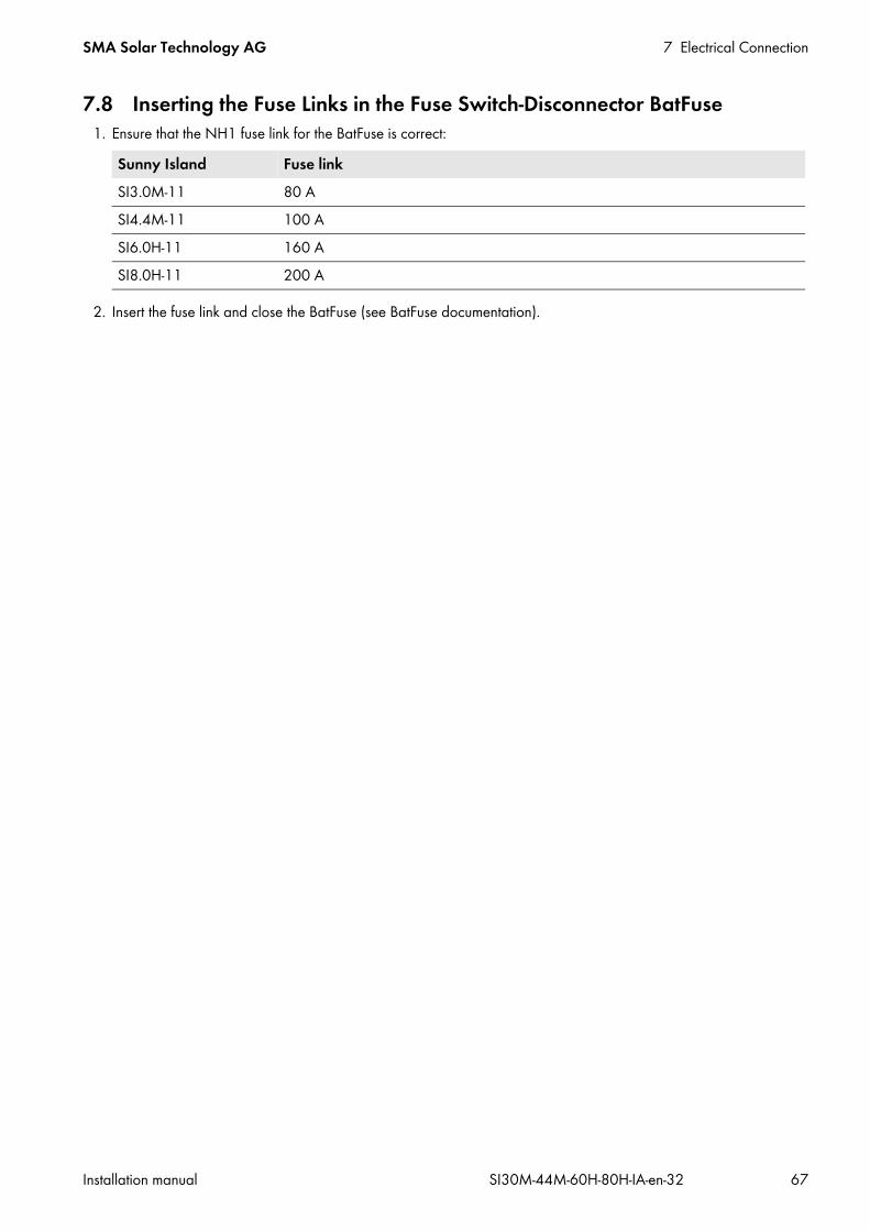
SMA Solar Technology AG 7 Electrical Connection
Installation manual SI30M-44M-60H-80H-IA-en-32 67
7.8 Inserting the Fuse Links in the Fuse Switch-Disconnector BatFuse1. Ensure that the NH1 fuse link for the BatFuse is correct:
2. Insert the fuse link and close the BatFuse (see BatFuse documentation).
Sunny Island Fuse linkSI3.0M-11 80 ASI4.4M-11 100 ASI6.0H-11 160 ASI8.0H-11 200 A

8 Commissioning SMA Solar Technology AG
68 SI30M-44M-60H-80H-IA-en-32 Installation manual
8 Commissioning8.1 Basic Configuration8.1.1 Starting the Quick Configuration GuideWith the Quick Configuration Guide (QCG), you can configure the settings required for operation.Step by step, the QCG requests the required settings for the system. Parameter setting for a cluster takes place centrally at the master. All slaves adopt the configuration automatically.
Requirements: The Sunny Remote Control must be connected to the master. All circuit breakers in the AC distribution board must be open. All Sunny Island inverters must be closed. All Sunny Island inverters must be switched off.
Procedure:1. Quickly close the load-break switch of the BatFuse and close the BatFuse (see BatFuse installation manual).2. Start the Sunny Island:
• In single systems, press the activation button on the Sunny Island.
• In a cluster, press and hold down the activation button on the master until an acoustic signal sounds. As a result, all Sunny Island inverters in the cluster are switched on.
3. When the Sunny Remote Control displays <Init System> , press and hold the button on the Sunny Remote Control (for operation of the Sunny Remote Control inverter, see the Sunny Island inverter operating manual). An acoustic signal sounds three times and the
Sunny Remote Control displays the QCG.
The Sunny Remote Control does not display the QCG?You have either pressed the button too late or not long enough.• Press the off button.• Repeat steps 2 and 3.
Configuration of the system using the QCGThe Sunny Island, which is connected to a Sunny Remote Control when starting to configure a new system, automatically becomes the master.
• During configuration, only the master may be connected to a Sunny Remote Control.• For a multicluster system, each cluster must be configured individually at the master.

SMA Solar Technology AG 8 Commissioning
Installation manual SI30M-44M-60H-80H-IA-en-32 69
8.1.2 Performing Basic Configuration of the Sunny IslandRequirements: The Sunny Remote Control must be connected to the master. All Sunny Island inverters must be switched on but not in operation (for how to switch on the Sunny Island inverter,
see the Sunny Island inverter operating manual). The Quick Configuration Guide (QCG) is started.
Procedure:1. Turn the button on the Sunny Remote Control to the right and
select New System.
2. Press the button.3. Turn the button to the right until Y flashes and press the button. This confirms your selection of New System.4. Set the parameters of the QCG (carry out basic configuration in accordance with the installed system, see quick
reference guide of the installed system).
8.1.3 Setting Sunny Island for Charge Controller / Sunny Island Charger in Off-Grid Systems
Requirement: For systems with a maximum of four Sunny Island Charger devices, all Sunny Island Charger devices must be
connected to the master via a communication bus.Procedure:
1. Log in to the communication product as Installer (see the user manual of the communication product) or switch to expert mode on the Sunny Remote Control (see the Sunny Island operating manual).
2. Select the parameter Type: other DC sources / 250.28 ChrgCtlOp and adjust as follows:
8.1.4 Commissioning the Battery Current Sensor in Off-Grid SystemsTo operate the battery current sensor, you must set the type of the battery current sensor and start the adjustments of the battery current sensor.The Sunny Island distinguishes between battery current sensors of the types 50 mV and 60 mV. The types reflect the amplification factor of the battery current sensor. The amplification factors are given in amperes per 50 mV or in amperes per 60 mV, e.g., 400 A/60 mV.Requirement: The Sunny Remote Control must be connected to the master.
Value ExplanationAuto System with AC sources (e.g., PV inverter)
The Sunny Island Charger or charge controller can also be present in the system.SMA System with Sunny Island Charger and without AC sources
A maximum of four Sunny Island Charger devices is installed.NoFrq System with charge controllers and without AC sources
The charge controllers are not Sunny Island Charger devices or the number is greater than four Sunny Island Chargers.

8 Commissioning SMA Solar Technology AG
70 SI30M-44M-60H-80H-IA-en-32 Installation manual
Procedure:1. Switch off the Sunny Island and open the BatFuse load-break
switch quickly.
2. Short-circuit the measuring cable at the battery current sensor. Connect the BatCur– and BatCur+ insulated measuring conductors to the connection for BatCur+.
3. Close the BatFuse load-break switch quickly and switch the Sunny Island on.
4. Switch to installer mode on the Sunny Remote Control (see Sunny Island operating manual).5. Select the parameter 225.01 BatCurSnsTyp and set to the type of the battery current sensor used.6. For a 60 mV model, select the parameter 225.02 BatCurGain60 and set it according to the gain factor of the
battery current sensor.7. For a 50 mV model, select the parameter 225.03 BatCurGain50 and set it according to the gain factor of the
battery current sensor.8. Select the parameter 225.04 BatCurAutoCal and set to Start.
The Sunny Island starts the adjustment.9. After ten seconds, select the parameter 120.06 TotBatCur and read off the value.
The parameter value is between 0 A and 1 A. The parameter value is not between 0 A and 1 A.
The measuring cables are not correctly connected or not short-circuited.• Check whether the measuring cables are correctly connected and whether they are short-circuited.• Repeat steps 8 and 9.

SMA Solar Technology AG 8 Commissioning
Installation manual SI30M-44M-60H-80H-IA-en-32 71
10. Switch off the Sunny Island and open the BatFuse load-break switch quickly.
11. Connect the BatCur+ insulated measuring conductor on the side for connecting the BatFuse.
12. Connect the BatCur– insulated measuring conductor on the side for connecting the battery.
13. Close the BatFuse load-break switch quickly and switch on the Sunny Island.
8.1.5 Setting the Functions of the Multifunction RelaysThe multifunction relays of the master are preset in an SMA Flexible Storage System and cannot be changed.In multicluster systems with Multicluster Box 12 (MC-BOX-12.3-20), multifunction relays 1 and 2 in the master of the main cluster and multifunction relay 1 in slave 1 of the main cluster are set permanently. Note the function of the multifunction relays in the following table during the electrical connection (see Section 7.4, page 28).Table for configuring the operating modes of the multifunction relay (for your own notes):Multifunction relay Parameter Value Function/outputRelay 1 of Sunny Island inverter/master
241.01 Rly1Op
Relay 2 of Sunny Island inverter/master
241.02 Rly2Op
Relay 1 of Slave 1 244.01 Rly1OpSlv1
Relay 2 of Slave 1 244.02 Rly2OpSlv1

8 Commissioning SMA Solar Technology AG
72 SI30M-44M-60H-80H-IA-en-32 Installation manual
Procedure:1. Log in to the communication product as Installer (see the user manual of the communication product) or switch to
expert mode on the Sunny Remote Control (see the Sunny Island operating manual).2. Set the parameter for the multifunction relay functions as shown in the table above.
8.2 Battery Management8.2.1 Safety When Setting the Battery Management ParametersThis section contains safety information to be observed when configuring the battery management. To prevent property damage and to ensure the long-term operation of the product, read this section carefully and observe all safety information.
8.2.2 Adjusting the Battery Management to the BatteryFor further information relating to the battery management and the charging behavior of the Sunny Island inverter, see the technical information “Battery Management” on the supplied CD.You can set the parameters for battery management on the communication product or on the Sunny Remote Control. Procedure:
1. Log in to the communication product as Installer (see the user manual of the communication product) or switch to expert mode on the Sunny Remote Control (see the Sunny Island operating manual).
2. To set the parameters for battery management on the Sunny Explorer, click on the tab Settings on the Sunny Explorer and select the group Battery > Charge.
3. Select the parameter Maximum battery charging current / 222.01 BatChrgCurMax and set it to the maximum battery charging current recommended by the battery manufacturer.
4. Set the parameters for boost charge:• Select the parameter Time for boost charge of battery / 222.02 AptTmBoost and set to the boost-charge
absorption time recommended by the battery manufacturer.• Select the parameter Cell charge setpoint voltage for boost charge / 222.07 ChrgVtgBoost and set it to
the cell-voltage setpoint recommended by the battery manufacturer for boost charge.
Relay 1 of Slave 2 245.01 Rly1OpSlv2
Relay 2 of Slave 2 245.02 Rly2OpSlv2
Damage to the battery due to incorrect settingsThe set battery parameters influence the charging behavior of the Sunny Island inverter. The battery can be damaged by incorrect settings of the battery type, nominal voltage and capacity parameters.
• Ensure that the values recommended by the battery manufacturer are set (refer to the technical data of the battery in the manufacturer documentation). Note that the battery charging behavior names used by SMA Solar Technology AG and the battery manufacturer may, in some cases, differ in meaning (for the battery charging behavior of the Sunny Island inverter, see technical information “Battery Management”).
• Set the battery capacity for a ten-hour electric discharge (C10) The battery manufacturer specifies the battery capacity in relation to discharge time.
Multifunction relay Parameter Value Function/output
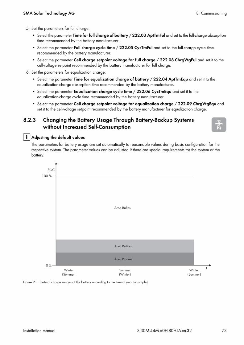
SMA Solar Technology AG 8 Commissioning
Installation manual SI30M-44M-60H-80H-IA-en-32 73
5. Set the parameters for full charge:• Select the parameter Time for full charge of battery / 222.03 AptTmFul and set to the full-charge absorption
time recommended by the battery manufacturer.• Select the parameter Full charge cycle time / 222.05 CycTmFul and set to the full-charge cycle time
recommended by the battery manufacturer.• Select the parameter Cell charge setpoint voltage for full charge / 222.08 ChrgVtgFul and set it to the
cell-voltage setpoint recommended by the battery manufacturer for full charge.6. Set the parameters for equalization charge:
• Select the parameter Time for equalization charge of battery / 222.04 AptTmEqu and set it to the equalization-charge absorption time recommended by the battery manufacturer.
• Select the parameter Equalization charge cycle time / 222.06 CycTmEqu and set it to the equalization-charge cycle time recommended by the battery manufacturer.
• Select the parameter Cell charge setpoint voltage for equalization charge / 222.09 ChrgVtgEqu and set it to the cell-voltage setpoint recommended by the battery manufacturer for equalization charge.
8.2.3 Changing the Battery Usage Through Battery-Backup Systems without Increased Self-Consumption
Figure 21: State of charge ranges of the battery according to the time of year (example)
Adjusting the default valuesThe parameters for battery usage are set automatically to reasonable values during basic configuration for the respective system. The parameter values can be adjusted if there are special requirements for the system or the battery.

8 Commissioning SMA Solar Technology AG
74 SI30M-44M-60H-80H-IA-en-32 Installation manual
The following ranges result from the parameter default values:
You can change the battery usage through battery-backup systems without increased self-consumption on the communication product or Sunny Remote Control. Procedure:
1. Log in to the communication product as Installer (see the user manual of the communication product) or switch to expert mode on the Sunny Remote Control (see the Sunny Island operating manual).
2. Set the following parameters for increased self-consumption:
Range Explanation of the range and parameters Behavior of the Sunny Island inverterBuRes Range for battery-backup function The Sunny Island uses this range for supplying the
battery-backup grid when the utility grid fails. When the utility grid is available again, the battery is charged by the Sunny Island with nominal power from the utility grid.
Minimum width of the battery-backup range / 262.03 BUResSOC
BatRes Range for protection against deep dischargeThis range can only be reached when the utility grid fails.
The Sunny Island switches into standby mode. The Sunny Island starts up every two hours and attempts to charge the battery with PV energy. If the battery cannot be charged, the Sunny Island switches back to standby mode.When the utility grid is available again, the battery is charged by the Sunny Island with nominal power from the utility grid.
Minimum width of the deep-discharge protection range / 262.02 BatResSOC
ProtRes Range for protection in the event of deep dischargeThis range can only be reached when the utility grid fails.
When this range is reached, the Sunny Island switches off in order to protect the battery. When the utility grid is available again, the system must be charged manually (“Charging the Battery after Auto Power Off”, see Sunny Island operating manual).
Lower limit of the deep-discharge protection range before disconnection / 262.01 ProtResSOC
Range Lead-acid battery Lithium-ion batteryBuRes 15% to 100% 13% to 100%BatRes 10% to 15% 3% to 13%ProtRes 0% to 10% 0% to 3%
Procedure for multicluster systems with battery-backup gridWith the Multicluster Box 12 (MC-Box-12.3-20) and the NA Box or Grid Connect Box, multicluster systems with battery-backup grid can be installed (see Multicluster Box and NA Box / Grid Connect Box documentation).
• In a multicluster system with battery-backup grid, set the ranges of battery state of charge for each cluster to the same values.
Parameter ValueIncreased self-consumption switched on / 261.01 SlfCsmpIncEna DisableLower limit of the deep-discharge protection range before disconnection / 262.01 ProtResSOC
–
Minimum width of the deep-discharge protection range / 262.02 BatResSOC
–

SMA Solar Technology AG 8 Commissioning
Installation manual SI30M-44M-60H-80H-IA-en-32 75
8.2.4 Battery Usage through Systems for Increased Self-Consumption8.2.4.1 Seasonal Adjustment of the Battery UsageThe options for increased self-consumption depend to a large extent on the battery and on the availability of PV energy. In order to use the battery optimally, you can adjust the depth of discharge of the battery to the application.In many regions, the PV energy available largely depends on the season and the hours of sunshine. On short days with few hours of sunlight, the Sunny Island cannot charge the battery fully. Lead-acid batteries in particular age faster due to low charging over a long period. Therefore, it is better if the battery is not discharged too much by the Sunny Island on short days. On short days, there is insufficient PV energy to charge the battery. On long days with many hours of sunlight, the Sunny Island can usually charge the battery fully. On such days, it is better to use as much of the battery capacity as possible for increasing self-consumption.The discharge behavior can be adjusted to the location and time by the Sunny Island. You can activate seasonal adjustment for this (parameter Seasonal operation active / 261.03 Saisonenable). The Sunny Island only uses a small portion of battery capacity for increased self-consumption on short days when adjustment is activated. The Sunny Island uses a large portion of the battery capacity for the increased self-consumption on long days. The seasonal adjustment prolongs the electrical endurance of the battery in regions where the available PV energy is largely dependent on the season.
8.2.4.2 Changing the Battery Usage through Systems for Increased Self-Consumption without a Battery-Backup Function
In systems for increased self-consumption, one range can be adjusted seasonally:• Increased self-consumption range (SlfCsmp)
You determine the percentage of the battery capacity that is to be used for increased self-consumption on the shortest day of the year.
The longer the days become, the more the SlfCsmp range increases automatically and the range for protection against deep discharge (BatRes) decreases. The range for increased self-consumption reaches its maximum on the longest day:
SlfCsmpmax = 100% − 262.04 PVResSOC − 262.02 BatResSOC − 262.01 ProtResSOCThis results in the seasonal progression of the ranges.
Minimum width of the battery-backup range / 262.03 BUResSOC
If all ranges combined do not amount to 100%, the BuRes range will be increased automatically.
Seasonal operation active / 261.03 Saisonenable No
Adjusting the default valuesThe parameters for battery usage are set automatically to reasonable values during basic configuration for the respective system. The parameter values can be adjusted if there are special requirements for the system or the battery.
Parameter Value
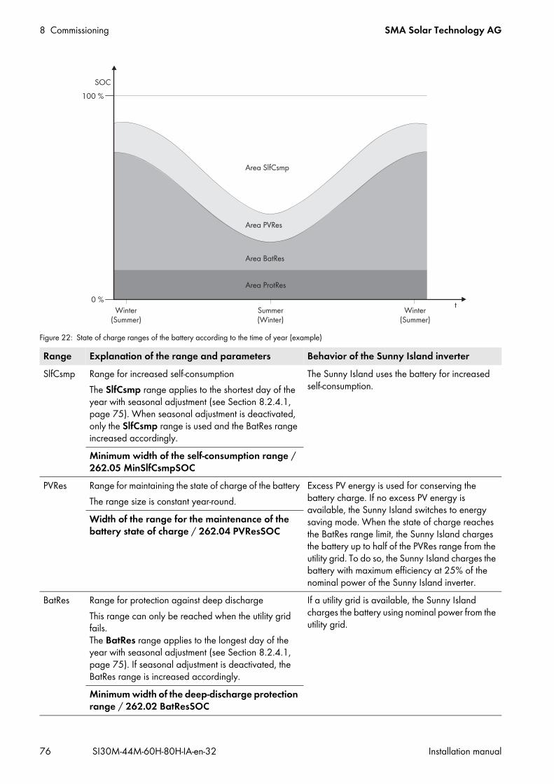
8 Commissioning SMA Solar Technology AG
76 SI30M-44M-60H-80H-IA-en-32 Installation manual
Figure 22: State of charge ranges of the battery according to the time of year (example)
Range Explanation of the range and parameters Behavior of the Sunny Island inverterSlfCsmp Range for increased self-consumption
The SlfCsmp range applies to the shortest day of the year with seasonal adjustment (see Section 8.2.4.1, page 75). When seasonal adjustment is deactivated, only the SlfCsmp range is used and the BatRes range increased accordingly.
The Sunny Island uses the battery for increased self-consumption.
Minimum width of the self-consumption range / 262.05 MinSlfCsmpSOC
PVRes Range for maintaining the state of charge of the batteryThe range size is constant year-round.
Excess PV energy is used for conserving the battery charge. If no excess PV energy is available, the Sunny Island switches to energy saving mode. When the state of charge reaches the BatRes range limit, the Sunny Island charges the battery up to half of the PVRes range from the utility grid. To do so, the Sunny Island charges the battery with maximum efficiency at 25% of the nominal power of the Sunny Island inverter.
Width of the range for the maintenance of the battery state of charge / 262.04 PVResSOC
BatRes Range for protection against deep dischargeThis range can only be reached when the utility grid fails. The BatRes range applies to the longest day of the year with seasonal adjustment (see Section 8.2.4.1, page 75). If seasonal adjustment is deactivated, the BatRes range is increased accordingly.
If a utility grid is available, the Sunny Island charges the battery using nominal power from the utility grid.
Minimum width of the deep-discharge protection range / 262.02 BatResSOC

SMA Solar Technology AG 8 Commissioning
Installation manual SI30M-44M-60H-80H-IA-en-32 77
The following ranges result from the parameter default values:
The following ranges result from deactivating seasonal adjustment with the default values of the parameters:
You can change the battery usage through battery-backup systems without increased self-consumption on the communication product or Sunny Remote Control.Requirement: The system must not be a battery-backup system.
ProtRes Range for protection in the event of deep dischargeThis range can only be reached when the utility grid fails.
When this range is reached, the Sunny Island switches off in order to protect the battery. When the utility grid is available again, the system must be charged manually (“Charging the Battery after Auto Power Off”, see Sunny Island operating manual).
Lower limit of the deep-discharge protection range before disconnection / 262.01 ProtResSOC
Range Lead-acid battery Lithium-ion batteryShortest day*
* December 21 (northern hemisphere) or June 21 (southern hemisphere)
Longest day**
** June 21 (northern hemisphere) or December 21 (southern hemisphere)
Shortest day* Longest day**MinSlfCsmp 65% to 100% 45% to 100% 30% to 100% 10% to 100%PVRes 60% to 65% 40% to 45% 25% to 30% 5% to 10%BatRes 10% to 60% 10% to 40% 3% to 25% 3% to 5%ProtRes 0% to 10% 0% to 10% 0% to 3% 0% to 3%
Range Lead-acid battery Lithium-ion batteryMinSlfCsmp 65% to 100% 30% to 100%PVRes 60% to 65% 25% to 30%BatRes 10% to 60% 3% to 25%ProtRes 0% to 10% 0% to 3%
Range Explanation of the range and parameters Behavior of the Sunny Island inverter

8 Commissioning SMA Solar Technology AG
78 SI30M-44M-60H-80H-IA-en-32 Installation manual
Procedure:1. Log in to the communication product as Installer (see the user manual of the communication product) or switch to
expert mode on the Sunny Remote Control (see the Sunny Island operating manual).2. Set the following parameters for the battery usage:
A parameter cannot be adjusted?All ranges combined result in a value greater than 100%.• Ensure that all ranges have been set correctly.
8.2.4.3 Changing the Battery Usage through Battery-Backup Systems with Increased Self-Consumption
Two ranges can be adjusted seasonally in battery-backup systems with increased self-consumption:• Range for increased self-consumption (MinSlfCsmp)
You determine the percentage of the battery capacity that is to be used for increased self-consumption on the shortest day of the year.
• Range for battery-backup function (BURes)You specify the percentage of the battery capacity that is to be used for the battery-backup function on the longest day.
The longer the days become, the more the SlfCsmp range automatically increases and the BURes range decreases. The range for increased self-consumption reaches its maximum on the longest day:
SlfCsmpmax = 100% − 262.04 PVResSOC − 262.03 BUResSOC − 262.02 BatResSOC − 262.01 ProtResSOC
Parameter ValueIncreased self-consumption switched on / 261.01 SlfCsmpIncEna EnableLower limit of the deep-discharge protection range before disconnection / 262.01 ProtResSOC
–
Minimum width of the deep-discharge protection range / 262.02 BatResSOC
The range remains constant year-round when seasonal adjustment is deactivated.
Width of the range for the maintenance of the battery state of charge / 262.04 PVResSOC
–
Minimum width of the self-consumption range / 262.05 MinSlfCsmpSOC
When seasonal adjustment is deactivated, this value is used year-round for increased self-consumption.
Highest yielding month for battery utilization range / 261.02 SlfCsmpPosSel
North for northern hemisphere* or South for southern hemisphere**
* Set the value to North when June is the month with the highest yield.** Set the value to South when December is the month with the highest yield.
Seasonal operation active / 261.03 Saisonenable No for no seasonal adjustment or Yes for seasonal adjustment
Adjusting the default valuesThe parameters for battery usage are set automatically to reasonable values during basic configuration for the respective system. The parameter values can be adjusted if there are special requirements for the system or the battery.
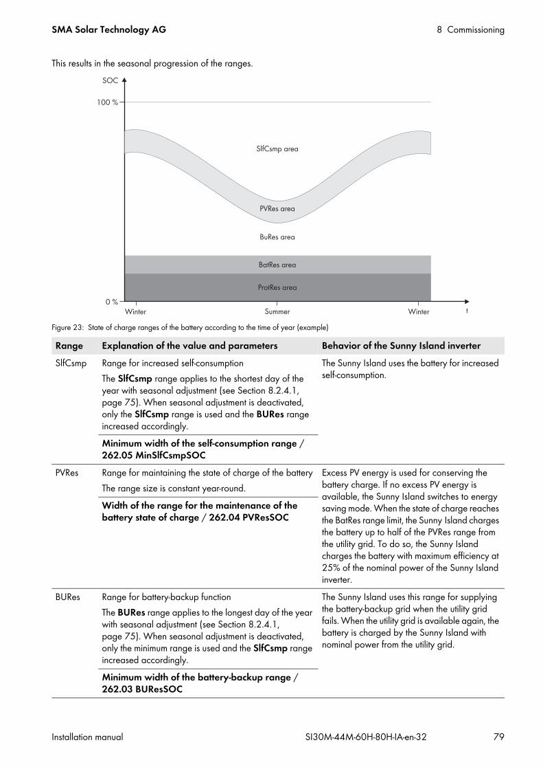
SMA Solar Technology AG 8 Commissioning
Installation manual SI30M-44M-60H-80H-IA-en-32 79
This results in the seasonal progression of the ranges.
Figure 23: State of charge ranges of the battery according to the time of year (example)
Range Explanation of the value and parameters Behavior of the Sunny Island inverterSlfCsmp Range for increased self-consumption
The SlfCsmp range applies to the shortest day of the year with seasonal adjustment (see Section 8.2.4.1, page 75). When seasonal adjustment is deactivated, only the SlfCsmp range is used and the BURes range increased accordingly.
The Sunny Island uses the battery for increased self-consumption.
Minimum width of the self-consumption range / 262.05 MinSlfCsmpSOC
PVRes Range for maintaining the state of charge of the batteryThe range size is constant year-round.
Excess PV energy is used for conserving the battery charge. If no excess PV energy is available, the Sunny Island switches to energy saving mode. When the state of charge reaches the BatRes range limit, the Sunny Island charges the battery up to half of the PVRes range from the utility grid. To do so, the Sunny Island charges the battery with maximum efficiency at 25% of the nominal power of the Sunny Island inverter.
Width of the range for the maintenance of the battery state of charge / 262.04 PVResSOC
BURes Range for battery-backup functionThe BURes range applies to the longest day of the year with seasonal adjustment (see Section 8.2.4.1, page 75). When seasonal adjustment is deactivated, only the minimum range is used and the SlfCsmp range increased accordingly.
The Sunny Island uses this range for supplying the battery-backup grid when the utility grid fails. When the utility grid is available again, the battery is charged by the Sunny Island with nominal power from the utility grid.
Minimum width of the battery-backup range / 262.03 BUResSOC

8 Commissioning SMA Solar Technology AG
80 SI30M-44M-60H-80H-IA-en-32 Installation manual
The following ranges result from the parameter default values:
The following ranges result from deactivating seasonal adjustment with the default values of the parameters:
You can change the battery usage through battery-backup systems with increased self-consumption on the communication product or Sunny Remote Control.Procedure:
1. Log in to the communication product as Installer (see the user manual of the communication product) or switch to expert mode on the Sunny Remote Control (see the Sunny Island operating manual).
BatRes Range for protection against deep discharge This range can only be reached when the utility grid fails.
The Sunny Island switches into standby mode. The Sunny Island starts up every two hours and attempts to charge the battery with PV energy. If the battery cannot be charged, the Sunny Island switches back to standby mode.When the utility grid is available, the Sunny Island charges the battery with nominal power from the utility grid.
Minimum width of the deep-discharge protection range / 262.02 BatResSOC
ProtRes Range for protection in the event of deep dischargeThis range can only be reached when the utility grid fails.
When this range is reached, the Sunny Island switches off in order to protect the battery. When the utility grid is available again, the system must be charged manually (“Charging the Battery after Auto Power Off”, see Sunny Island operating manual).
Lower limit of the deep-discharge protection range for disconnection / 262.01 ProtResSOC
Range Lead-acid battery Lithium-ion batteryShortest day*
* December 21 (northern hemisphere) or June 21 (southern hemisphere)
Longest day**
** June 21 (northern hemisphere) or December 21 (southern hemisphere)
Shortest day* Longest day**SlfCsmp 65% to 100% 45% to 100% 30% to 100% 28% to 100%PVRes 60% to 65% 40% to 45% 25% to 30% 23% to 28%BURes 15% to 60% 15% to 40% 13% to 25% 13% to 23%BatRes 10% to 15% 10% to 15% 3% to 13% 3% to 13%ProtRes 0% to 10% 0% to 10% 0% to 3% 0% to 3%
Range Lead-acid battery Lithium-ion batterySlfCsmp 65% to 100% 30% to 100%PVRes 60% to 65% 25% to 30%BURes 15% to 60% 13% to 25%BatRes 10% to 15% 3% to 13%ProtRes 0% to 10% 0% to 3%
Procedure for multicluster systems with battery-backup gridWith the Multicluster Box 12 (MC-Box-12.3-20) and the NA Box or Grid Connect Box, multicluster systems with battery-backup grid can be installed (see Multicluster Box and NA Box / Grid Connect Box documentation).
• In a multicluster system with battery-backup grid, set the ranges of battery state of charge for each cluster to the same values.
Range Explanation of the value and parameters Behavior of the Sunny Island inverter

SMA Solar Technology AG 8 Commissioning
Installation manual SI30M-44M-60H-80H-IA-en-32 81
2. Set the following parameters for increased self-consumption:
A parameter cannot be adjusted?All ranges combined result in a value greater than 100%.• Ensure that all ranges have been set correctly.
8.2.5 Changing the Battery Protection Mode in Off-Grid Systems
Function of the battery protection modeThe battery protection mode protects the battery.If the state of charge (SOC) of the battery falls below the thresholds, battery protection mode is activated. In battery protection mode, the Sunny Island switches to standby mode or switches itself off. The battery protection mode has three levels. One state of charge threshold can be set for each level. Levels 1 and 2 of the battery protection mode have specific start and end times and are therefore dependent on the time of day (see Section 9.3 "Setting Time-Dependent Functions", page 100).
• Level 1If the state of charge falls below the threshold for level 1, the Sunny Island switches to standby between the start time and end time. This way you can specify preferred times for the Sunny Island to be switched off if an energy deficit occurs.
Parameter ValueIncreased self-consumption switched on / 261.01 SlfCsmpIncEna EnableLower limit of the deep-discharge protection range before disconnection / 262.01 ProtResSOC
–
Minimum width of the deep-discharge protection range / 262.02 BatResSOC
–
Minimum width of the battery-backup range / 262.03 BUResSOC
The range remains constant year-round when seasonal adjustment is deactivated.
Width of the range for the maintenance of the battery state of charge / 262.04 PVResSOC
–
Minimum width of the self-consumption range / 262.05 MinSlfCsmpSOC
When seasonal adjustment is deactivated, this value is used year-round for increased self-consumption.
Highest yielding month for battery utilization range / 261.02 SlfCsmpPosSel
North for northern hemisphere* or South for southern hemisphere**
* Set the value to North when June is the month with the highest yield.** Set the value to South when December is the month with the highest yield.
Seasonal operation active / 261.03 Saisonenable No for no seasonal adjustment or Yes for seasonal adjustment
Battery protection mode for lithium-ion batteries cannot be changedYou can only change the battery protection mode if you are using lead-acid batteries. When using lithium-ion batteries, the battery protection mode cannot be changed.

8 Commissioning SMA Solar Technology AG
82 SI30M-44M-60H-80H-IA-en-32 Installation manual
• Level 2If the SOC drops below the threshold for level 2, the Sunny Island switches to standby. Use the start time and end time to define the time window in which no energy is anticipated from AC sources. Outside this time window, the Sunny Island starts up every two hours to charge the battery. If no energy is available to charge the battery, the Sunny Island remains on standby.This means that, for example, in stand-alone grids with PV inverters, you can specify that the Sunny Island does not start up at night, preventing it from consuming energy from the battery.
• Level 3If the state of charge falls below the threshold for level 3, the Sunny Island switches itself off. This protects the battery against deep discharge and severe damage. To charge the battery again, the Sunny Island must be switched on and started manually.
At all three levels, the Sunny Island will only switch to standby mode or switch itself off if no charging current has flowed in the battery for at least five minutes.Recharging the battery with an external energy source:In levels 1 and 2 of battery protection mode, you can charge the battery at any time with an external energy source. If a voltage is present on connection AC2, the Sunny Island exits standby mode.If the Sunny Island has switched to level 3 of battery protection mode by itself, you must charge the battery in emergency charge mode (see the Sunny Island inverter operating manual).Time settings:The start time and the end time can be configured for battery protection mode levels 1 and 2.If the state of charge falls below the threshold for level 1, the Sunny Island switches to standby between the start time and end time.If the state of charge falls below the threshold for level 2, the Sunny Island switches to standby between the start time and end time. The Sunny Island attempts to charge the battery in the remaining time.You can change the battery protection mode on the communication product or on the Sunny Remote Control. The parameters for the battery protection mode are created as a data field in the communication product. Data fields enable the summary of parameters. Therefore, the parameters in the Sunny Explorer are shown in a table. Requirement: In a cluster, the communication product or Sunny Remote Control must be connected to the master.
Procedure:1. Log in to the communication product as Installer (see the user manual of the communication product) or switch to
expert mode on the Sunny Remote Control (see the Sunny Island operating manual).2. To change battery protection mode 1, set the desired times and SOC thresholds:
• Select the parameter Start time battery protection mode / 223.01 BatPro1TmStr and set to the desired start time for level 1.
• Select the parameter End time battery protection mode / 223.02 BatPro1TmStp and set to the desired end time for level 1.
• Select the parameter Battery state of charge for protection mode / 223.05 BatPro1Soc and set to the desired SOC threshold for level 1.
3. To change battery protection mode 2, set the desired times and SOC thresholds:• Select the parameter Start time battery protection mode / 223.03 BatPro2TmStr and set to the desired
start time for level 2.• Select the parameter End time battery protection mode / 223.04 BatPro2TmStp and set to the desired end
time for level 2.• Select the parameter Battery state of charge for protection mode / 223.06 BatPro2Soc and set to the
desired SOC threshold for level 2.4. To change battery protection mode 3, select the parameter 223.07 BatPro3Soc and set to the desired SOC
threshold.

SMA Solar Technology AG 8 Commissioning
Installation manual SI30M-44M-60H-80H-IA-en-32 83
Configuring the resistance of the battery cableYou can optimize the battery management if you set the resistance of the battery cable in expert mode.
Figure 24: Designation of the cableThe resistance of the battery cable is composed of the resistance of cable 1, the BatFuse and the resistance of cable 2.Requirement: In a cluster, the communication product or Sunny Remote Control must be connected to the master.
Procedure:1. Calculate the individual cable resistances. Use the following formula:
RCu(l,A) = resistance of the cableρ = specific resistance of copper (ρ = 0.018 Ω mm²⁄m)l = total length of the conductor (outward conductor + return conductor = twice the cable length) in mA = conductor cross-section in mm²
2. Calculate the total resistance of the battery cable. Use the following formula:RBatRes = RCable 1 + RBatFuse + RCable 2
RBatRes = total resistance of the battery cableRCable 1 = calculated resistance of cable 1RCable 2 = calculated resistance of cable 2RBatFuse = calculated resistance of BatFuse = 2 m Ω
3. Log in to the communication product as Installer (see the user manual of the communication product) or switch to expert mode on the Sunny Remote Control (see the Sunny Island operating manual).
4. Select the parameter Cable resistance of the battery connection / 221.06 BatWirRes and set to the resistance of the battery cable.
8.2.6 Setting the Control of the Battery Room Fan1. Log in to the communication product as Installer (see the user manual of the communication product) or switch to
expert mode on the Sunny Remote Control (see the Sunny Island operating manual).
RCu l A, lA------=

8 Commissioning SMA Solar Technology AG
84 SI30M-44M-60H-80H-IA-en-32 Installation manual
• Select the parameter Temperature limit for multifunction relay with battery room fan / 221.07 BatFanTmpStr and set it to the battery temperature at which the fan is to be switched on.
2. Ensure that the multifunction relay used for control is set to BatFan or MccBatFan (see Section 8.1.5 "Setting the Functions of the Multifunction Relays", page 71).
3. Ensure that the battery room is sufficiently ventilated in the case of malfunctions – for example, on failure of the multifunction relay.
8.3 Energy Management8.3.1 Setting Load Shedding in a Multicluster SystemThe load contactor in the Multicluster Box is a load-shedding contactor and is controlled depending on the state of charge of the batteries.Significance of the SOC thresholds:When the state of charge of a battery reaches the lower SOC threshold, the load contactor is opened. The state of charge of the battery of the main cluster and the states of charge of the batteries of the extension clusters are evaluated. The load contactor disconnects the loads from the stand-alone grid. When the state of charge of all batteries reaches the upper SOC threshold during recharging, the load contactor closes. The load-shedding contactor connects the loads to the stand-alone grid.You can change the battery protection mode on the communication product or on the Sunny Remote Control. Requirement: The communication product or Sunny Remote Control must be connected to the master of the main cluster.
Procedure:1. Log in to the communication product as Installer (see the user manual of the communication product) or switch to
expert mode on the Sunny Remote Control (see the Sunny Island operating manual).2. Select the parameter Battery state of charge limit for load shedding 1 start / 242.01 Lod1SocTm1Str and
set it to the lower SOC threshold.3. Select the parameter Battery state of charge limit for load shedding 1 stop / 242.02 Lod1SocTm1Stp and
set it to the upper SOC threshold. The upper SOC threshold must be at least 10 percentage points above the lower SOC threshold.
4. Set the parameter Time load shedding 1 / 242.05 Lod1Tm1Str and the parameter Start time for the additional time period of load shedding 1 / 242.06 Lod1Tm2Str each to the same value, e.g., to 00:00:00. This will switch the time-dependent load shedding off.
5. If the off-grid system is a multicluster system, ensure that the parameter of the multifunction relay is set to MccAutoLod (see Section 8.1.5 "Setting the Functions of the Multifunction Relays", page 71).
SMA Solar Technology AG 8 Commissioning
Installation manual SI30M-44M-60H-80H-IA-en-32 85
8.3.2 Setting One-Level Load SheddingOne multifunction relay controls the load-shedding contactor depending on the state of charge of the battery.Significance of the SOC thresholds:When the state of charge of the battery reaches the lower SOC threshold, the multifunction relay opens the connected load-shedding contactor. The load-shedding contactor disconnects the loads from the stand-alone grid. When the state of charge of the battery reaches the upper SOC threshold during recharging, the multifunction relay closes the connected load-shedding contactor. The load-shedding contactor connects the loads to the stand-alone grid.You can change the battery protection mode on the communication product or on the Sunny Remote Control.Requirement: In a cluster, the communication product or Sunny Remote Control must be connected to the master.
Procedure:1. Log in to the communication product as Installer (see the user manual of the communication product) or switch to
expert mode on the Sunny Remote Control (see the Sunny Island operating manual).2. Select the parameter Battery state of charge limit for load shedding 1 start / 242.01 Lod1SocTm1Str and
set it to the lower SOC threshold.3. Select the parameter Battery state of charge limit for load shedding 1 stop / 242.02 Lod1SocTm1Stp and
set it to the upper SOC threshold. The upper SOC threshold must be at least 10 percentage points above the lower SOC threshold.
4. Set the parameter Time load shedding 1 / 242.05 Lod1Tm1Str and the parameter Start time for the additional time period of load shedding 1 / 242.06 Lod1Tm2Str each to the same value, e.g., to 00:00:00. This will switch the time-dependent load shedding off.
5. If the loads are only to be reconnected when the set SOC threshold is reached, ensure that the parameter of the multifunction relay is set to AutoLod1Soc (see Section 8.1.5 "Setting the Functions of the Multifunction Relays", page 71).
6. If the loads are to be supplied by an external energy source during recharging of the battery, ensure the following:• Ensure that the parameter of the multifunction relay is set to AutoLodExt (see Section 8.1.5 "Setting the Functions
of the Multifunction Relays", page 71).• Ensure that the external energy source can supply the loads with sufficient power.
7. If the off-grid system is a multicluster system, ensure that the parameter of the multifunction relay is set to MccAutoLod (see Section 8.1.5 "Setting the Functions of the Multifunction Relays", page 71).
8.3.3 Setting Two-Level Load SheddingTwo multifunction relays control two load-shedding contactors depending on the state of charge of the battery.Significance of the SOC thresholds:Two lower and two upper SOC thresholds each are available for controlling the load-shedding contactors. The load-shedding contactors disconnect the loads from the utility grid if the states of charge are as follows:
• When the state of charge of the battery reaches the first lower SOC threshold, the multifunction relay opens the connected load-shedding contactor for the first level of load shedding. The load-shedding contactor disconnects those loads from the utility grid that are to be disconnected for the first level.
• When the state of charge of the battery reaches the second lower SOC threshold, the multifunction relay opens the connected load-shedding contactor for the second level of load shedding. The load-shedding contactor disconnects the remaining loads from the utility grid.
• When the state of charge of the battery reaches the second upper SOC threshold during recharging, the multifunction relay closes the connected load-shedding contactor for the second level of load shedding. The load-shedding contactor connects those loads to the utility grid that were disconnected for the second level .

8 Commissioning SMA Solar Technology AG
86 SI30M-44M-60H-80H-IA-en-32 Installation manual
• When the state of charge of the battery reaches the first upper SOC threshold during recharging, the multifunction relay closes the connected load-shedding contactor for the first level of load shedding. The load-shedding contactor connects those loads to the utility grid that were disconnected for the first level. All loads are connected to the utility grid.
Requirement: In a cluster, the communication product or Sunny Remote Control must be connected to the master.
Procedure:1. Log in to the communication product as Installer (see the user manual of the communication product) or switch to
expert mode on the Sunny Remote Control (see the Sunny Island operating manual).2. Setting the first level of load shedding:
• Select the parameter Battery state of charge limit for load shedding 1 start / 242.01 Lod1SocTm1Str and set it to the lower SOC threshold.
• Select the parameter Battery state of charge limit for load shedding 1 stop / 242.02 Lod1SocTm1Stp and set it to the upper SOC threshold.
• Set the parameter Time load shedding 1 / 242.05 Lod1Tm1Str and the parameter Start time for the additional time period of load shedding 1 / 242.06 Lod1Tm2Str each to the same value, e.g., to 00:00:00. This will switch the time-dependent load shedding off.
• Ensure that the parameter of the multifunction relay is set to AutoLod1Soc (see Section 8.1.5 "Setting the Functions of the Multifunction Relays", page 71).
3. Setting the second level of load shedding:• Select the parameter Battery state of charge limit for load shedding 2 start / 242.07 Lod2SocTm1Str
and set it to the lower SOC threshold.• Select the parameter Battery state of charge limit for load shedding 2 stop in the additional time period
/ 242.08 Lod2SocTm1Stp and set it to the upper SOC threshold.• Set the parameter Time load shedding 2 / 242.11 Lod2Tm1Str and the parameter Start time for the
additional time period of load shedding 2 / 242.12 Lod2Tm2Str each to the same value, e.g., to 00:00:00. This will switch the time-dependent load shedding off.
• Ensure that the parameter of the multifunction relay is set to AutoLod2Soc (see Section 8.1.5 "Setting the Functions of the Multifunction Relays", page 71).
8.3.4 Setting Time-Dependent One-Level Load SheddingThe time-dependent load shedding divides the day into two time periods (see Section 9.3 "Setting Time-Dependent Functions", page 100). You set the SOC thresholds that apply for each time period. For example, you can set that no loads are to be disconnected from the utility grid during the night where possible.Significance of the SOC thresholds:When the state of charge of the battery reaches the lower SOC threshold, the multifunction relay opens the connected load-shedding contactor. The load-shedding contactor disconnects the loads from the utility grid. When the state of charge of the battery reaches the upper SOC threshold during recharging, the multifunction relay closes the connected load-shedding contactor. The load-shedding contactor connects the loads to the utility grid.

SMA Solar Technology AG 8 Commissioning
Installation manual SI30M-44M-60H-80H-IA-en-32 87
Requirement: In a cluster, the communication product or Sunny Remote Control must be connected to the master.
Procedure:1. Log in to the communication product as Installer (see the user manual of the communication product) or switch to
expert mode on the Sunny Remote Control (see the Sunny Island operating manual).2. Set the parameters for the standard time period:
• Select the parameter Time load shedding 1 / 242.05 Lod1Tm1Str and set to the start time for the standard time period.
• Select the parameter Battery state of charge limit for load shedding 1 start / 242.01 Lod1SocTm1Str and set it to the lower SOC threshold for the standard time period.
• Select the parameter Battery state of charge limit for load shedding 1 stop / 242.02 Lod1SocTm1Stp and set it to the upper SOC threshold for the standard time period.
3. Set the parameters for the additional time period:• Select the parameter Start time for the additional time period of load shedding 1 / 242.06 Lod1Tm2Str
and set to the start time for the additional time period.• Select the parameter Battery state of charge limit for load shedding 1 start in the additional time period
/ 242.03 Lod1SocTm2Str and set it to the lower SOC threshold for the additional time period.• Select the parameter Battery state of charge limit for load shedding 1 stop in the additional time period
/ 242.04 Lod1SocTm2Stp and set it to the upper SOC threshold for the additional time period.4. Ensure that the multifunction relay used for control is set to AutoLod1Soc (see Section 8.1.5 "Setting the Functions
of the Multifunction Relays", page 71).
Example: from 10:00 p.m. to 6:00 a.m., the load-shedding contactor is not to disconnect the loads from the utility grid where possible.
Figure 25: Profile of the SOC thresholds for controlling the load-shedding contactor and the start times for the time periodsFor the standard time period, the start time is set to 6:00 a.m. and the end time to 10:00 p.m. The lower SOC threshold is set to 40% and the upper SOC threshold is set to 80% in this time period.For the additional time period, the start time is set to 10:00 p.m. and the end time to 6:00 a.m. The lower SOC threshold is set to 30% SOC and the upper SOC threshold is set to 40% SOC in this time period.
8 Commissioning SMA Solar Technology AG
88 SI30M-44M-60H-80H-IA-en-32 Installation manual
8.3.5 Setting Time-Dependent Two-Level Load SheddingThe time-dependent load shedding divides the day into two time periods (see Section 9.3 "Setting Time-Dependent Functions", page 100). You set the SOC thresholds that apply for each time period for two-level load shedding. For example, you can set that as far as possible no loads are to be disconnected from the utility grid during the day.Significance of the SOC thresholds:Two lower and two upper SOC thresholds are available for each time period for controlling the load-shedding contactors. The load-shedding contactors disconnect the loads from the utility grid if the states of charge are as follows:
• When the state of charge of the battery reaches the first lower SOC threshold, the multifunction relay opens the connected load-shedding contactor for the first level of load shedding. The load-shedding contactor disconnects those loads from the utility grid that are to be disconnected for the first level.
• When the state of charge of the battery reaches the second lower SOC threshold, the multifunction relay opens the connected load-shedding contactor for the second level of load shedding. The load-shedding contactor disconnects the remaining loads from the utility grid.
• When the state of charge of the battery reaches the second upper SOC threshold during recharging, the multifunction relay closes the connected load-shedding contactor for the second level of load shedding. The load-shedding contactor connects those loads to the utility grid that were disconnected for the second level .
• When the state of charge of the battery reaches the first upper SOC threshold during recharging, the multifunction relay closes the connected load-shedding contactor for the first level of load shedding. The load-shedding contactor connects those loads to the utility grid that were disconnected for the first level. All loads are now reconnected to the utility grid.
Requirement: In a cluster, the communication product or Sunny Remote Control must be connected to the master.
Procedure:1. Log in to the communication product as Installer (see the user manual of the communication product) or switch to
expert mode on the Sunny Remote Control (see the Sunny Island operating manual).2. Select the parameter Time load shedding 1 / 242.05 Lod1Tm1Str and set to the start time for the standard time
period.3. Select the parameter Start time for the additional time period of load shedding 1 / 242.06 Lod1Tm2Str
and set to the start time for the additional time period.4. Set the SOC threshold for the standard time period:
• Select the parameter Battery state of charge limit for load shedding 1 start / 242.01 Lod1SocTm1Str and set it to the lower SOC threshold for the first level of load shedding.
• Select the parameter Battery state of charge limit for load shedding 1 stop / 242.02 Lod1SocTm1Stp and set it to the upper SOC threshold for the first level of load shedding.
• Select the parameter Battery state of charge limit for load shedding 2 start / 242.07 Lod2SocTm1Str and set it to the lower SOC threshold for the second level of load shedding.
• Select the parameter Battery state of charge limit for load shedding 2 stop in the additional time period / 242.08 Lod2SocTm1Stp and set it to the upper SOC threshold for the second level of load shedding.
5. Set the SOC threshold for the additional time period:• Select the parameter Battery state of charge limit for load shedding 1 start in the additional time
period / 242.03 Lod1SocTm2Str and set it to the lower SOC threshold for the first level of load shedding.• Select the parameter Battery state of charge limit for load shedding 1 stop in the additional time
period / 242.04 Lod1SocTm2Stp and set it to the upper SOC threshold for the second level of load shedding.• Select the parameter Battery state of charge limit for load shedding 2 start in the additional time
period / 242.09 Lod2SocTm2Str and set it to the lower SOC threshold for the second level of load shedding.• Select the parameter Battery state of charge limit for load shedding 2 stop in the additional time
period / 242.10 Lod2SocTm2Stp and set it to the upper SOC threshold for the second level of load shedding.

SMA Solar Technology AG 8 Commissioning
Installation manual SI30M-44M-60H-80H-IA-en-32 89
6. Ensure that the multifunction relay used for controlling the first level of load shedding is set to AutoLod1Soc (see Section 8.1.5 "Setting the Functions of the Multifunction Relays", page 71).
7. Ensure that the multifunction relay used for controlling the second level of load shedding is set to AutoLod2Soc.
8.3.6 Setting Utilization of Excess Energy in Off-Grid Systems
Figure 26: Switching-on time and switching-off time for utilization of excess energy during constant voltage phaseThe Sunny Island controls the utilization of excess energy during the constant voltage phase depending on the cell voltage of the battery. During the constant voltage phase, the battery is charged with a constant charging voltage. When the setpoint of the cell voltage in the constant voltage phase is reached, the multifunction relay is activated. The multifunction relay remains in this position for the minimum time 241.07 ExtPwrDerMinTm. If the cell voltage differs by more than 241.08 ExtPwrDerDltVtg from the setpoint of the cell voltage, the multifunction relay is deactivated. The setpoint of the cell voltage depends on the charging process during the constant voltage phase.
To control the utilization of excess energy, set the multifunction relay on the Sunny Remote Control as follows: It is not possible to set the multifunction relay on the communication product for utilization of excess energy.Procedure:
1. Switch to expert mode on the Sunny Remote Control (see the Sunny Island operating manual).2. Select the parameter 241.07 ExtPwrDerMinTm and set it to the minimum time that the multifunction relay remains
activated.3. Select the parameter 241.08 ExtPwrDerDltVtg and set it to the voltage difference relative to the setpoint of the
cell voltage during the constant voltage phase.
4. Ensure that the multifunction relay used for control is set to ExtPwrDer (see Section 8.1.5 "Setting the Functions of the Multifunction Relays", page 71).
Charging process Parameter Default valueBoost charge Cell charge setpoint voltage for boost charge / 222.07 ChrgVtgBoost 2.40 VFull charge Cell charge setpoint voltage for full charge / 222.08 ChrgVtgFul 2.45 VEqualization charge Cell charge target voltage for equalization charge /
222.09 ChrgVtgEqu2.45 V
Recording of the measured values of the cell voltage reacts to changes with time-lagThe Sunny Island calculates the cell voltage from the measured battery voltage. The Sunny Island calculates an average from the measured values of the battery voltage. As a result of the calculation of an average, the cell voltage that is recorded reacts to changes with a time-lag.
8 Commissioning SMA Solar Technology AG
90 SI30M-44M-60H-80H-IA-en-32 Installation manual
8.4 Generator Management8.4.1 Configuration of the Thresholds for Generator Connection8.4.1.1 Changing the Current limit for the GeneratorSignificance of the current limits:The generator management limits the consumption of generator current to the maximum set value.In three-phase systems, the generator current is limited for each line conductor individually. The set value applies to each line conductor.For Sunny Island inverters that are operated in parallel, the generator management only limits the total generator current. The generator current may be unequally distributed to the Sunny Island inverters. If a Sunny Island fails, for example, more current flows through the remaining Sunny Island inverters.Enhanced generator management:If the set generator current is not sufficient for supplying the loads, the generator management requests additional current from the battery. The system then supplies the loads with the generator current and the battery current.Procedure:
1. Log in to the communication product as Installer (see the user manual of the communication product) or switch to expert mode on the Sunny Remote Control (see the Sunny Island operating manual).
2. Select the parameter Nominal generator current / 234.03 GnCurNom and set to the desired value. Tip: A suitable value for this parameter is 80% of the maximum generator current per line conductor.
8.4.1.2 Changing the Voltage Thresholds for the GeneratorThe voltage thresholds determine the range within which the generator voltage is allowed to fluctuate. When the Sunny Island switches to the generator, the stand-alone grid will also fluctuate within this range.A breach of the set voltage thresholds leads to disconnection of the line conductor from the stand-alone grid or the generator not being switched on.Procedure:
1. Log in to the communication product as Installer (see the user manual of the communication product) or switch to expert mode on the Sunny Remote Control (see the Sunny Island operating manual).
2. Select the parameter Voltage monitoring generator lower minimum threshold / 234.01 GNVtgMin and set to the minimum generator voltage.
3. Select the parameter Voltage monitoring generator upper maximum threshold / 234.02 GnVtgMax and set to the maximum generator voltage.
8.4.1.3 Changing the Frequency Thresholds of the Generator VoltageThe frequency thresholds determine the range within which the frequency of the generator voltage is allowed to fluctuate. When the Sunny Island switches to the generator, the stand-alone grid will also fluctuate within this range.A breach of the set frequency thresholds leads to the disconnection of the line conductors from the stand-alone grid or to the generator not being connected.Procedure:
1. Log in to the communication product as Installer (see the user manual of the communication product) or switch to expert mode on the Sunny Remote Control (see the Sunny Island operating manual).
2. Select the parameter Nominal generator frequency / 234.04 GnFrqNom and set to the rated frequency of the generator voltage.

SMA Solar Technology AG 8 Commissioning
Installation manual SI30M-44M-60H-80H-IA-en-32 91
3. Select the parameter Frequency monitoring generator lower minimum threshold / 234.05 GnFrqMin and set to the minimum frequency of the generator voltage.
4. Select the parameter Frequency monitoring generator upper maximum threshold / 234.06 GnFrqMin and set to the maximum frequency of the generator voltage.
8.4.1.4 Changing the Permitted Reverse Power in the GeneratorIf the reverse power for the set time is exceeded, all Sunny Island inverters disconnect the generator from the stand-alone grid and block the connection of the generator to the stand-alone grid for the minimum stop time.
Procedure:1. Log in to the communication product as Installer (see the user manual of the communication product) or switch to
expert mode on the Sunny Remote Control (see the Sunny Island operating manual).2. Select the parameter Voltage monitoring generator maximum reverse power / 234.13 GnRvPwr and set
to the active power of the generator reverse power.3. Select the parameter Voltage monitoring generator maximum reverse power tripping time /
234.14 GnRvTm and set to time period of the generator reverse power.
8.4.1.5 Configuring the Current Limit for the Generator Depending on the Frequency
The higher the generator current, the higher the torque for the generator. With unregulated generators, the speed of rotation decreases with increasing torque. If the speed of rotation decreases, the frequency of the generator voltage is reduced.If the frequency of the generator voltage falls below the rated frequency, the generator management can place additional limits on the generator current. The lower the frequency, the more the generator current is limited by the generator management. This setting is useful if the generator is supplying other loads parallel to the Sunny Island. This setting allows the maximum load to be placed on the generator without overloading it.Requirement: The generator must not be an inverter generator. The output frequency of the inverter generator is fixed.
Procedure:1. Log in to the communication product as Installer (see the user manual of the communication product) or switch to
expert mode on the Sunny Remote Control (see the Sunny Island operating manual).2. Select the parameter Nominal generator current / 234.03 GnCurNom and set to the desired value. Tip: A
suitable value for the parameter 234.03 GnCurNom is 80% of the maximum generator current per line conductor.3. Select the parameter Type of generator current limitation / 234.15 GnCtlMod and set to CurFrq. This will
activate the frequency-dependent current limiting.
8.4.2 Changing the Type of the Generator InterfaceIf you have installed a generator in the system, the type of generator interface determines how the generator is controlled.
Generator damageIn the event of reverse power, the AC sources in the stand-alone grid drive the generator. The generator can be damaged as a result.
• Observe the manufacturer’s information on reverse power protection of the generator.• Set the generator reverse power and permitted time for reverse power according to the manufacturer’s
specifications.

8 Commissioning SMA Solar Technology AG
92 SI30M-44M-60H-80H-IA-en-32 Installation manual
Procedure:1. Log in to the communication product as Installer (see the user manual of the communication product) or switch to
expert mode on the Sunny Remote Control (see the Sunny Island operating manual).2. If the generator has an autostart function, select the parameter Generator request / 234.07 GnStrMod and set
to Autostart.3. If the generator does not have an autostart function, select the parameter Generator request /
234.07 GnStrMod and set to Manual.
8.4.3 Configuring Generator Run Times8.4.3.1 Changing the Warm-Up Time for the GeneratorRelation between warm-up time and termination of generator start:The generator management measures the time between the generator start and the beginning of the warm-up time. If a maximum time is exceeded, the generator management terminates the generator start. The maximum time to start termination is double the warm-up time plus an additional two minutes.With some generator types, the generator only switches the voltage to the output of the generator after the internal warm-up time has expired. During this time, the generator management is unable to recognize a valid generator voltage. If the warm-up time is set too low, the generator management terminates the generator start before the internal warm-up time has expired.Procedure:
1. Log in to the communication product as Installer (see the user manual of the communication product) or switch to expert mode on the Sunny Remote Control (see the Sunny Island operating manual).
2. Select the parameter Generator warm-up time / 234.12 GnWarmTm.3. Set the selected parameter according to the generator properties.
The generator start is not terminated prematurely.
8.4.3.2 Changing the Minimum Run Time for the Generator1. Log in to the communication product as Installer (see the user manual of the communication product) or
switch to expert mode on the Sunny Remote Control (see the Sunny Island operating manual).2. Select the parameter Minimum run time of the generator / 234.08 GnOpTmMin and set to the desired value.
8.4.3.3 Changing the Power-Down Time for the Generator
Procedure:1. Log in to the communication product as Installer (see the user manual of the communication product) or switch to
expert mode on the Sunny Remote Control (see the Sunny Island operating manual).2. Select the parameter Cool-down time of the generator / 234.10 GnCoolTm and set to the desired value.
Generator properties Setting the parametersWithout internal warm-up time • Set the desired warm-up time.With internal warm-up time Autostart compatible • Set the warm-up time to be at least half the
internal warm-up time of the generator.Without an autostart function
Internal shut-off delay of the generatorGenerators may have an internal shut-off delay which is activated only once the generator request has been removed. Note that this internal shut-off delay increases the actual power-down time.
SMA Solar Technology AG 8 Commissioning
Installation manual SI30M-44M-60H-80H-IA-en-32 93
8.4.3.4 Changing the Minimum Stop Time for the Generator1. Log in to the communication product as Installer (see the user manual of the communication product) or
switch to expert mode on the Sunny Remote Control (see the Sunny Island operating manual).2. Select the parameter Minimum idle time of the generator / 234.09 GnStpTmMin and set to the desired value.
8.4.4 Configuring the Generator Request8.4.4.1 Changing the Automatic Generator OperationIn automatic generator operation, the generator management specifies when and for how long the generator runs, depending on the configuration.Procedure:
1. Log in to the communication product as Installer (see the user manual of the communication product) or switch to expert mode on the Sunny Remote Control (see the Sunny Island operating manual).
2. To deactivate automatic generator mode, select the parameter 235.01 GnAutoEna / Automatic generator start and set it to Disable.
3. To activate automatic generator mode, select the parameter 235.01 GnAutoEna / Automatic generator start and set it to Enable.
8.4.4.2 Changing a State-Of-Charge-Dependent Generator RequestIf the battery reaches the lower SOC threshold, the generator management requests the generator. If the battery reaches the upper SOC threshold during recharging, the generator management resets this generator request.Procedure:
1. Log in to the communication product as Installer (see the user manual of the communication product) or switch to expert mode on the Sunny Remote Control (see the Sunny Island operating manual).
2. Select the parameter Battery state of charge limit for generator start / 235.03 GnSocTm1Str and set it to the lower SOC threshold.
3. Select the parameter Battery state of charge limit for generator disconnection / 235.04 GnSocTm1Stp and set it to the upper SOC threshold.
4. Set the parameter End time additional time period generator request / 235.07 GnTm1Str and Start time additional time period generator request / 235.08 GnTm2Str to the same value, e.g., to 00:00:00. This deactivates the time-dependent generator request.
8.4.4.3 Setting a Time-Dependent Generator RequestThe time-dependent generator request divides the day into two time periods. For each time period, you set which conditions there are for the generator request (see Section 9.3 "Setting Time-Dependent Functions", page 100). In this way, you can, for example, set the generator not to start at night. This ensures that the noise pollution produced by the generator takes place during the day whenever possible.Both time periods each have a lower and an upper SOC threshold. If the battery reaches the lower SOC threshold, the generator management requests the generator. When the battery reaches the upper SOC threshold during recharging, generator management resets this generator request. The following settings are possible for the SOC thresholds:
• The lower SOC threshold is lower than the upper SOC threshold.The generator is requested during this time period depending on the state of charge.
• The lower SOC threshold is higher than or equal to the upper SOC threshold.The generator is not started depending on the state of charge. In this time period, the other settings for the generator request, e.g., the time-dependent generator request, apply.

8 Commissioning SMA Solar Technology AG
94 SI30M-44M-60H-80H-IA-en-32 Installation manual
Procedure:1. Log in to the communication product as Installer (see the user manual of the communication product) or switch to
expert mode on the Sunny Remote Control (see the Sunny Island operating manual).2. Set the parameters for the standard time period:
• Select the parameter End time additional time period generator request / 235.07 GnTm1Str and set it to the start time for the standard time period.
• Select the parameter Battery state of charge limit for generator start / 235.03 GnSocTm1Str and set it to the lower SOC threshold during the standard time period.
• Select the parameter Battery state of charge limit for generator disconnection / 235.04 GnSocTm1Stp and set it to the upper SOC threshold during the standard time period.
3. Set the parameters for the additional time period:• Select the parameter Start time for the additional time period of generator request / 235.08 GnTm2Str
and set to the start time for the additional time period.• Select the parameter Battery state of charge limit for generator start in the additional time period /
235.05 GnSocTm2Str and set it to the lower SOC threshold during the additional time period.• Select the parameter Battery state of charge limit for generator disconnection in the additional time
period / 235.06 GnSocTm2Stp and set it to the upper SOC threshold during the additional time period.
8.4.4.4 Configuring the Load-Dependent Generator RequestSignificance of the load-dependent generator request:If you activate the load-dependent generator request, the Sunny Island requests the generator in the event of a high load. This prevents the battery from deep electric discharging and cycling and extends its service life. The performance of the off-grid system for supplying loads increases to the sum of the generator power and the power of the Sunny Island inverter. This improves the system stability. The load is the average output power of the Sunny Island inverter.
Example: from 10:00 p.m. to 6:00 a.m., the generator is not to start where possible.
Figure 27: Profile of the SOC and the times for generator requestsFor the standard time period, the start time is set to 6:00 a.m. and the end time to 10:00 p.m. The lower SOC threshold is set to 40% and the upper SOC threshold is set to 80% in this time period.For the additional time period, the start time is set to 10:00 p.m. and the end time to 6:00 a.m. The lower SOC threshold is set to 30% SOC and the upper SOC threshold is set to 40% SOC in this time period.

SMA Solar Technology AG 8 Commissioning
Installation manual SI30M-44M-60H-80H-IA-en-32 95
Loads in a three-phase system:The generator management considers the total load of all phases. It does not monitor single phases in three-phase systems. If the switch-on power limit is exceeded, the generator management requests the generator.Time-based procedure of the load-dependent generator request:If the switch-on power limit is reached, the generator management requests the generator. If the load then drops to the switch-off power limit, the generator management resets the generator request after the minimum run time. The generator management does not record the load as an instantaneous value. The generator management calculates the load during the averaging time 235.12 GnPwrAvgTm. The greater the averaging time that you set, the less the generator management reacts to load peaks.Generator run times:The warm-up, minimum and power-down times are adhered to after the generator start. The power of the generator is not immediately available in the stand-alone grid. Each start also means that the generator runs for at least the warm-up time, minimum run time and power-down time.Procedure:
1. Log in to the communication product as Installer (see the user manual of the communication product) or switch to expert mode on the Sunny Remote Control (see the Sunny Island operating manual).
2. Select the parameter Generator request via power on / 235.09 GnPwrEna and set to Enable. This will activate the load-dependent generator request.
3. Select the parameter Generator start load limit / 235.10 GnPwrStr and set to the switch-on power limit.4. Select the parameter Generator shutdown load limit / 235.11 GnPwrStp and set to the switch-off power limit.5. Select the parameter Averaging time for generator request based on power / 235.12 GnPwrAvgTm and
set to the averaging time with which the generator management calculates the average power.
8.4.4.5 Time-Controlled Generator RequestingIf the generator is requested dependent on time, it is requested on certain days for a set duration (see Section 9.4 "Setting Time-Controlled Functions", page 100).Procedure:
1. Log in to the communication product as Installer (see the user manual of the communication product) or switch to expert mode on the Sunny Remote Control (see the Sunny Island operating manual).
2. Select the parameter Time-controlled generator operation / 235.13 GnTmOpEna and set it to Enable.3. To set start date and start time on the Sunny Remote Control, set the parameter 235.14 GnTmOpStrDt to the
desired start date and the parameter 235.15 GnTmOpStrTm the desired start time.4. To set the start date and start time on the communication product, select the parameter Start time for
time-controlled generator operation and set the desired start date and time of the generator.5. Select the parameter Run time for time-controlled generator operation / 235.16 GnTmOpRnDur and set it
to the desired duration.6. Select the parameter Repetition cycle for time-controlled inverter operation / 235.17 GnTmOpCyc and set
it to the desired repetition cycle.Value ExplanationSingle Single generator request on the start dateDaily Daily generator request starting on the start dateWeekly Weekly generator request starting on the start date
The start date determines the weekday.
8 Commissioning SMA Solar Technology AG
96 SI30M-44M-60H-80H-IA-en-32 Installation manual
8.4.4.6 Changing the Generator Request via the Charging Process of the Battery1. Log in to the communication product as Installer (see the user manual of the communication product) or
switch to expert mode on the Sunny Remote Control (see the Sunny Island operating manual).2. Select the parameter Generator request in configured charge mode / 235.18 GnStrChrgMod and set to the
desired generator request:
8.4.4.7 Setting an External Generator RequestAn external control signal can transmit a generator request to the generator management.Procedure:
1. Log in to the communication product as Installer (see the user manual of the communication product) or switch to expert mode on the Sunny Remote Control (see the Sunny Island operating manual).
2. In order to activate the external generator request, select the parameter Reaction to digital input of the generator request / 235.19 GnStrDigIn and set to Enable.
3. In order to deactivate the external generator request, select the parameter Reaction to digital input of the generator request / 235.19 GnStrDigIn and set to Disable.
8.4.5 Configuring the Procedure in the Event of a Generator False StartOperating procedure if a generator false start is detected:If the Sunny Island detects a generator false start (e.g., voltage too high), the Sunny Island does not connect the stand-alone grid to the generator.If there is another request for the generator after the minimum stop time, the Sunny Island attempts to start the generator.If the Sunny Island detects a false start on numerous occasions and the number of failed attempts exceeds the maximum value, the Sunny Island switches into error status.After the stop time 234.11 GnErrStpTm has expired, the Sunny Island attempts to restart the generator.Single cluster systems:The generator management classes a line conductor fault on the master as a generator failure. All Sunny Island inverters disconnect the stand-alone grid from the generator.The generator management treats a fault on the slave line conductor as a line conductor fault. The slave disconnects only the affected line conductor from the stand-alone grid. The slave switches the stand-alone grid to the generator again if the faulty line conductor is in the valid range.Procedure:
1. Log in to the communication product as Installer (see the user manual of the communication product) or switch to expert mode on the Sunny Remote Control (see the Sunny Island operating manual).
2. In order to change the maximum number of failed attempts on the Sunny Remote Control:• Select the parameter 235.01 GnAutoEna and set it to Enable.• Select the parameter 235.02 GnAutoStr and set to the desired number of start attempts.
3. In order to change the maximum number of failed attempts on the communication product:• Select the parameter Automatic generator start.• Activate the automatic generator start and set the desired number of start attempts (see user manual of the
communication product).
Value ExplanationEqual Generator request during equalization chargeFull Generator request during full chargeBoth Generator request during equalization and full chargeOff Deactivation of the generator request via the charging process of the battery

SMA Solar Technology AG 8 Commissioning
Installation manual SI30M-44M-60H-80H-IA-en-32 97
4. In order to change the stop time of the generator after the maximum number of start attempts has been exceeded, select the parameter Idle time after generator error / 234.11 GnErrStpTm and set to the desired stop time.
8.5 Setting the Time ControlThe time control controls up to two multifunction relays according to the set times.Procedure:
1. Log in to the communication product as Installer (see the user manual of the communication product) or switch to expert mode on the Sunny Remote Control (see the Sunny Island operating manual).
2. To set the start date, select and set the following parameters:
3. To set the desired running time, select and set the following parameters:
4. To set the desired repetition cycle, select and set the following parameters:
8.6 Changing Thresholds for Systems for Increased Self-ConsumptionThe Sunny Island meets the requirements of the application rule “VDE-AR-N 4105:2011-08 - Power generation systems connected to the low-voltage distribution network - Technical minimum requirements for the connection to and parallel operation with low-voltage distribution networks”. In the Sunny Island, the application rule is defined as standard country data set VDE-AR-4105.In certain countries, the settings may need to be modified for connection of the Sunny Island inverter to the utility grid.Procedure:
• If the operation of the Sunny Island connected to the utility grid is allowed and an adjustment is necessary, change the Sunny Island according to the documentation (see www.SMA-Solar.com).
8.7 Changing the Automatic Frequency Synchronization in Off-Grid Systems
Automatic frequency synchronization enables the use of clocks which use the power frequency as a timer. The power frequency determines the accuracy of the clock. For power frequencies with constant frequency deviations from the rated frequency, the time indications will become more and more inaccurate.Continuous frequency deviations occur in off-grid systems with generators, for example. If the automatic frequency synchronization is activated, the Sunny Island regulates the frequency deviations over time. As a result, the accuracy of clocks that use the power frequency as timers is increased.
Possible settings ParameterStart time for timer 1, date Start date relay control for timer 243.01 RlyTmr1StrDtStart time for timer 1, time 243.02 RlyTmr1StrTmStart time for timer 2, date 243.05 RlyTmr2StrDtStart time for timer 2, time 243.06 RlyTmr2StrTm
Possible settings ParameterRunning time for timer 1 Repetition cycle time relay
control for timer243.03 RlyTmr1Dur
Running time for timer 2 243.07 RlyTmr2Dur
Possible settings ParameterRepetition cycle for timer 1 Repetition cycle time relay
control for timer243.04 RlyTmr1Cyc
Repetition cycle for timer 2 243.08 RlyTmr2Cyc
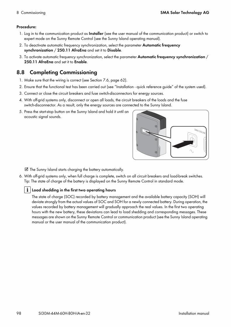
8 Commissioning SMA Solar Technology AG
98 SI30M-44M-60H-80H-IA-en-32 Installation manual
Procedure:1. Log in to the communication product as Installer (see the user manual of the communication product) or switch to
expert mode on the Sunny Remote Control (see the Sunny Island operating manual).2. To deactivate automatic frequency synchronization, select the parameter Automatic frequency
synchronization / 250.11 AfraEna and set it to Disable.3. To activate automatic frequency synchronization, select the parameter Automatic frequency synchronization /
250.11 AfraEna and set it to Enable.
8.8 Completing Commissioning1. Make sure that the wiring is correct (see Section 7.6, page 62).2. Ensure that the functional test has been carried out (see “Installation - quick reference guide” of the system used).3. Connect or close the circuit breakers and fuse switch-disconnectors for energy sources.4. With off-grid systems only, disconnect or open all loads, the circuit breakers of the loads and the fuse
switch-disconnector. As a result, only the energy sources are connected to the Sunny Island.5. Press the start-stop button on the Sunny Island and hold it until an
acoustic signal sounds.
The Sunny Island starts charging the battery automatically.6. With off-grid systems only, when full charge is complete, switch on all circuit breakers and load-break switches.
Tip: The state of charge of the battery is displayed on the Sunny Remote Control in standard mode.
Load shedding in the first two operating hoursThe state of charge (SOC) recorded by battery management and the available battery capacity (SOH) will deviate strongly from the actual values of SOC and SOH for a newly connected battery. During operation, the values recorded by battery management will gradually approach the real values. In the first two operating hours with the new battery, these deviations can lead to load shedding and corresponding messages. These messages are shown on the Sunny Remote Control or communication product (see the Sunny Island operating manual or the user manual of the communication product).

SMA Solar Technology AG 9 Supplementary Information
Installation manual SI30M-44M-60H-80H-IA-en-32 99
9 Supplementary Information9.1 Entering the SMA Grid Guard CodeDepending on the configuration, safety-relevant parameters are protected by the SMA Grid Guard code from unauthorized changes. You can unlock the parameters by entering the SMA Grid Guard code.Procedure:
1. Contact the SMA Service Line and apply for a personal SMA Grid Guard code.2. Log in to Sunny Explorer as Installer (see the user manual of the Sunny Explorer) or switch to expert mode on the
Sunny Remote Control (see the Sunny Island operating manual).3. To enter the SMA Grid Guard code on the Sunny Remote Control, select the parameter 270.01 Auth.Code and
set the SMA Grid Guard code.4. To enter the SMA Grid Guard code in the Sunny Explorer, select Options > SMA Grid Guard in the menu bar
and set the SMA Grid Guard code (see Sunny Explorer user manual). Safety-relevant parameters can now be changed.
9.2 Determining the Battery CapacityManufacturers state the battery capacity depending on the discharge time. In the configuration of the off-grid system and in the QCG, you always enter the battery capacity for a 10-hour electric discharge (C10). Procedure:
• Determine the battery capacity C10 specified by the battery manufacturer. You could determine the battery capacity C10. You could not determine the battery capacity C10?
• Estimate the battery capacity C10 from other discharge times. This will provide a value that is probably sufficient for commissioning.
• Contact the battery manufacturer, request the C10 battery capacity and set the correct battery capacity in the QCG as soon as possible. To do this, proceed as if you had replaced the battery (for battery replacement see the Sunny Island inverter operating manual).
Discharging time Estimation120 h (C120) C10 = C120⁄1.28100 h (C100) C10 = C100⁄1.2520 h (C20) C10 = C20⁄1.0910 h (C10) C10 = C105 h (C5) C10 = C5⁄0.881 h (C1) C10 = C1⁄0.61

9 Supplementary Information SMA Solar Technology AG
100 SI30M-44M-60H-80H-IA-en-32 Installation manual
9.3 Setting Time-Dependent FunctionsTime-dependent functions, such as time-dependent load shedding, split the day into two time periods. You specify the time periods using two points in time. The standard time period starts with time 1 and ends with time 2. The additional time period starts with time 2 and ends with time 1.
Figure 28: Division of the time of day into two time periods
9.4 Setting Time-Controlled FunctionsFor time-controlled functions, you set the start time, duration and repetition type.Example: Time-controlled operation of a generatorIf you want the generator to run every Monday from 07:00 a.m. to 08:00 a.m., Set the generator as follows:
• Time-controlled generator operation / 235.13 GnTmOpEna: Enable (activation of the function)• Start time for time-controlled generator operation / 235.14 GnTmOpStrDt: January 5, 2015 (Monday)• Start time for time-controlled generator operation / 235.15 GnTmOpStrTm: 07:00:00 (starting time)• Runtime for time-controlled generator operation / 235.16 GnTmOpRnDur: 01:00:00 (duration)• Repeat cycle for time-controlled generator operation / 235.17 GnTmOpCyc: Weekly (repetition type)
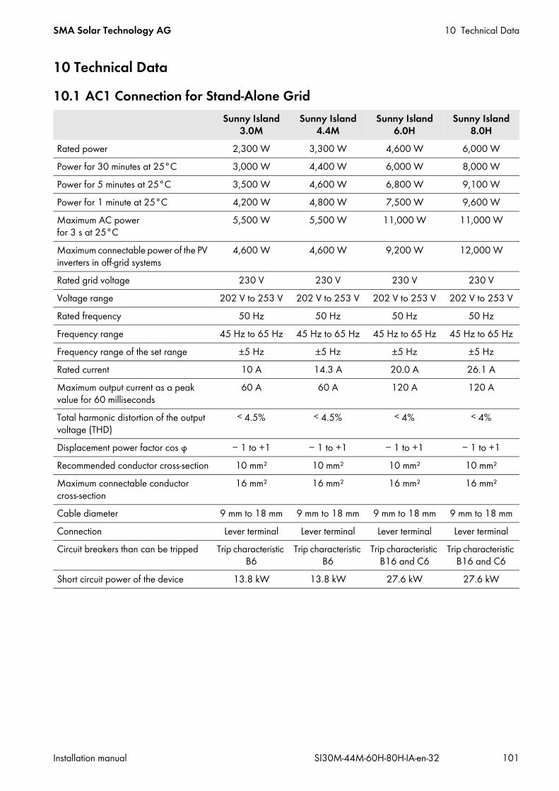
SMA Solar Technology AG 10 Technical Data
Installation manual SI30M-44M-60H-80H-IA-en-32 101
10 Technical Data10.1 AC1 Connection for Stand-Alone Grid
Sunny Island 3.0M
Sunny Island 4.4M
Sunny Island 6.0H
Sunny Island 8.0H
Rated power 2,300 W 3,300 W 4,600 W 6,000 WPower for 30 minutes at 25°C 3,000 W 4,400 W 6,000 W 8,000 WPower for 5 minutes at 25°C 3,500 W 4,600 W 6,800 W 9,100 WPower for 1 minute at 25°C 4,200 W 4,800 W 7,500 W 9,600 WMaximum AC power for 3 s at 25°C
5,500 W 5,500 W 11,000 W 11,000 W
Maximum connectable power of the PV inverters in off-grid systems
4,600 W 4,600 W 9,200 W 12,000 W
Rated grid voltage 230 V 230 V 230 V 230 VVoltage range 202 V to 253 V 202 V to 253 V 202 V to 253 V 202 V to 253 VRated frequency 50 Hz 50 Hz 50 Hz 50 HzFrequency range 45 Hz to 65 Hz 45 Hz to 65 Hz 45 Hz to 65 Hz 45 Hz to 65 HzFrequency range of the set range ±5 Hz ±5 Hz ±5 Hz ±5 HzRated current 10 A 14.3 A 20.0 A 26.1 AMaximum output current as a peak value for 60 milliseconds
60 A 60 A 120 A 120 A
Total harmonic distortion of the output voltage (THD)
˂ 4.5% ˂ 4.5% ˂ 4% ˂ 4%
Displacement power factor cos φ − 1 to +1 − 1 to +1 − 1 to +1 − 1 to +1Recommended conductor cross-section 10 mm² 10 mm² 10 mm² 10 mm²Maximum connectable conductor cross-section
16 mm² 16 mm² 16 mm² 16 mm²
Cable diameter 9 mm to 18 mm 9 mm to 18 mm 9 mm to 18 mm 9 mm to 18 mmConnection Lever terminal Lever terminal Lever terminal Lever terminalCircuit breakers than can be tripped Trip characteristic
B6Trip characteristic
B6Trip characteristic
B16 and C6Trip characteristic
B16 and C6Short circuit power of the device 13.8 kW 13.8 kW 27.6 kW 27.6 kW
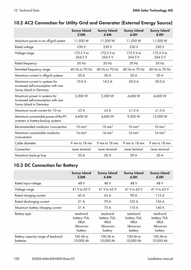
10 Technical Data SMA Solar Technology AG
102 SI30M-44M-60H-80H-IA-en-32 Installation manual
10.2 AC2 Connection for Utility Grid and Generator (External Energy Source)
10.3 DC Connection for Battery
Sunny Island 3.0M
Sunny Island 4.4M
Sunny Island 6.0H
Sunny Island 8.0H
Maximum power in an off-grid system 11,500 W 11,500 W 11,500 W 11,500 WRated voltage 230 V 230 V 230 V 230 VVoltage range 172.5 V to
264.5 V172.5 V to 264.5 V
172.5 V to 264.5 V
172.5 V to 264.5 V
Rated frequency 50 Hz 50 Hz 50 Hz 50 HzPermitted frequency range 40 Hz to 70 Hz 40 Hz to 70 Hz 40 Hz to 70 Hz 40 Hz to 70 HzMaximum current in off-grid systems 50 A 50 A 50 A 50 AMaximum current in systems for increased self-consumption with one Sunny Island in Germany
10.0 A 14.3 A 20.0 A 20.0 A
Maximum power in systems for increased self-consumption with one Sunny Island in Germany
2,300 W 3,300 W 4,600 W 4,600 W
Maximum inrush current for 10 ms ±3 A ±3 A ±1.5 A ±1.5 AMaximum connectable power of the PV inverters in battery-backup systems
4,600 W 4,600 W 9,200 W 12,000 W
Recommended conductor cross-section 10 mm² 10 mm² 10 mm² 10 mm²Maximum connectable conductor cross-section
16 mm² 16 mm² 16 mm² 16 mm²
Cable diameter 9 mm to 18 mm 9 mm to 18 mm 9 mm to 18 mm 9 mm to 18 mmConnection Lever terminal Lever terminal Lever terminal Lever terminalMaximum back-up fuse 50 A 50 A 50 A 50 A
Sunny Island 3.0M
Sunny Island 4.4M
Sunny Island 6.0H
Sunny Island 8.0H
Rated input voltage 48 V 48 V 48 V 48 VVoltage range 41 V to 63 V 41 V to 63 V 41 V to 63 V 41 V to 63 VRated charging current 45 A 63 A 90 A 115 ARated discharging current 51 A 75 A 103 A 136 AMaximum battery charging current 51 A 75 A 110 A 140 ABattery type Lead-acid
battery: FLA, VRLA
lithium-ion battery
Lead-acid battery: FLA,
VRLA lithium-ion
battery
Lead-acid battery: FLA,
VRLA lithium-ion
battery
Lead-acid battery: FLA,
VRLA lithium-ion
batteryBattery capacity range of lead-acid batteries
100 Ah to 10,000 Ah
100 Ah to 10,000 Ah
100 Ah to 10,000 Ah
100 Ah to 10,000 Ah

SMA Solar Technology AG 10 Technical Data
Installation manual SI30M-44M-60H-80H-IA-en-32 103
10.4 Efficiency
Battery capacity range of lithium-ion batteries
50 Ah to 10,000 Ah
50 Ah to 10,000 Ah
50 Ah to 10,000 Ah
50 Ah to 10,000 Ah
Recommended minimum battery capacity C10 in systems for increased self-consumption
100 Ah 100 Ah 100 Ah 100 Ah
Recommended minimum battery capacity C10 in battery-backup systems
100 Ah 100 Ah 120 Ah 160 Ah
Recommended minimum battery capacity C10 in off-grid systems
100 Ah 150 Ah 190 Ah 250 Ah
Recommended minimum battery capacity C10 per 1,000 Wp power of PV systems in off-grid systems
100 Ah 100 Ah 100 Ah 100 Ah
Charge control for lead-acid batteries IUoU charging behavior with automatic full charge and equalization
charge
IUoU charging behavior with automatic full charge and equalization
charge
IUoU charging behavior with automatic full charge and equalization
charge
IUoU charging behavior with automatic full charge and equalization
chargeDC connection Terminal lug M8,
20 mm to 25 mm wide
Terminal lug M8, 20 mm to 25 mm
wide
Terminal lug M8, 20 mm to 25 mm
wide
Terminal lug M8, 20 mm to 25 mm
widePermitted conductor cross-section 50 mm² to
95 mm²*50 mm² to 95 mm²*
50 mm² to 95 mm²*
50 mm² to 95 mm²*
Maximum connectable conductor cross-section
95 mm²* 95 mm²* 95 mm²* 95 mm²*
Cable diameter 14 mm to 25 mm 14 mm to 25 mm 14 mm to 25 mm 14 mm to 25 mmTorque 12 Nm 12 Nm 12 Nm 12 Nm
* In the event of a cross-section of 95 mm², observe the maximum cable diameter.
Sunny Island 3.0M
Sunny Island 4.4M
Sunny Island 6.0H
Sunny Island 8.0H
Maximum efficiency 95.5% 95.5% 95.8% 95.8%European weighted efficiency 94.0% 94.0% 94.3% 94.1%
Sunny Island 3.0M
Sunny Island 4.4M
Sunny Island 6.0H
Sunny Island 8.0H

10 Technical Data SMA Solar Technology AG
104 SI30M-44M-60H-80H-IA-en-32 Installation manual
10.5 Sunny Island 3.0M Efficiency Profile
Figure 29: Characteristic efficiency curve
10.6 Sunny Island 4.4M Efficiency Profile
Figure 30: Characteristic efficiency curve

SMA Solar Technology AG 10 Technical Data
Installation manual SI30M-44M-60H-80H-IA-en-32 105
10.7 Sunny Island 6.0H Efficiency Profile
Figure 31: Characteristic efficiency curve
10.8 Sunny Island 8.0H Efficiency Profile
Figure 32: Characteristic efficiency curve
10.9 Energy Consumption in No-Load Operation and StandbySunny Island 3.0M
Sunny Island 4.4M
Sunny Island 6.0H
Sunny Island 8.0H
Standby consumption 6.8 W 6.8 W 6.5 W 6.5 WConsumption in no-load operation and in discharge mode without SRC-20
18.0 W 18.0 W 25.8 W 25.8 W
Consumption in no-load operation and in discharge mode with SRC-20
18.8 W 18.8 W 26.6 W 26.6 W

10 Technical Data SMA Solar Technology AG
106 SI30M-44M-60H-80H-IA-en-32 Installation manual
10.10 Noise Emission
10.11 Grid Configuration
10.12 Protective Devices
10.13 Features
Noise emission, typical 49 dB(A)
TN-S grid configuration suitableTN-C-S grid configuration suitableTT grid configuration suitable
AC short-circuit yesAC overload yesDC reverse polarity protection not availableBattery deep discharge yesOvertemperature yesOvervoltage category according to IEC 60664-1 III
Number of buttons 3Number of LEDs 3 two-color LEDsDisplay External display SRC-20Number of interface slots 2SWDMSI-xx necessary in the SMA Flexible Storage SystemSI-COMSMA.BGx optionalCOM SYNC for internal communication onlySI-SYSCAN.BGx optional for Sunny Island 6.0H/8.0HNumber of digital control inputs 1High level digital input 9 V to 63 VLow level digital input 0 V to 3 VPotential-free control contacts 2 multifunction relaysNumber of connections for battery current sensors 1Measuring accuracy with connected battery current sensor ± 10%Maximum length of measuring cable on battery current sensor 3 mAC load switching limit for multifunction relays 1 and 2 1 A at 250 VDC load switching limit for multifunction relays 1 and 2 see Section 10.14, page 107

10.14 DC Load Limitation Curve of the Multifunction Relays
Figure 33: DC load limitation curve of multifunction relays 1 and 2
10.15 General DataSunny Island 3.0M/4.4M Sunny Island 6.0H/8.0H
Width x height x depth 467 mm x 612 mm x 242 mm 467 mm x 612 mm x 242 mmWeight 44 kg 63 kgOperating temperature range –25°C to +60°C –25°C to +60°CStorage temperature range − 25°C to +70°C − 25°C to +70°CHumidity 0% to 100% 0% to 100%Maximum installation height above MSL
3,000 m 3,000 m
Topology LF transformer LF transformerCooling method OptiCool OptiCoolProtection class in accordance with IEC 62103
I I
Climate category in accordance with IEC 60721
3K6 3K6
Degree of protection in accordance with IEC 60529
IP54 IP54

11 Accessories SMA Solar Technology AG
108 SI30M-44M-60H-80H-IA-en-32 Installation manual
11 AccessoriesThe following overview details the accessories and spare parts for your product. These can be ordered as required from SMA Solar Technology AG or your distributor.Designation Brief description SMA order numberBatfuse-B.01 (80 A, 100 A, 160 A, 200 A, 250 A)
2-pole LV/HRC battery fuse-switch-disconnector, size 1 for 1 Sunny Island, 3 DC inputs (1 x battery and 2 x Sunny Island Charger 50), 1 x auxiliary voltage output 8 A
BATFUSE-B.01*
* When ordering, additional details on the intended use are required.
Batfuse-B.03 (80 A, 100 A, 160 A, 200 A, 250 A)
2-pole LV/HRC battery fuse-switch-disconnector, size 1 for up to three Sunny Island units, 6 DC inputs (2 x battery and 4 x Sunny Island Charger 50), 1 x auxiliary voltage output 8 A
BATFUSE-B.03*
Load-shedding contactor Three-pole load-shedding contactor with 48 V DC coil for single-cluster systems with Sunny Island
SI-LS100-48
SI-Shunt Battery current sensorThe battery current sensor is available in different versions. You can obtain more information from your distributor or SMA Solar Technology AG.
SI-SHUNTXXX*
Sunny Island Charger 50 PV charge controller for off-grid systems SIC50-MPTSI-COMSMA.BGx RS485 communication interface SI-COMSMA-NRSI-SYSCAN.BGx Communication interface for communication between
clusters in a multicluster systemSI-SYSCAN-NR
SWDMSI Sunny Island Speedwire data module SWDMSI
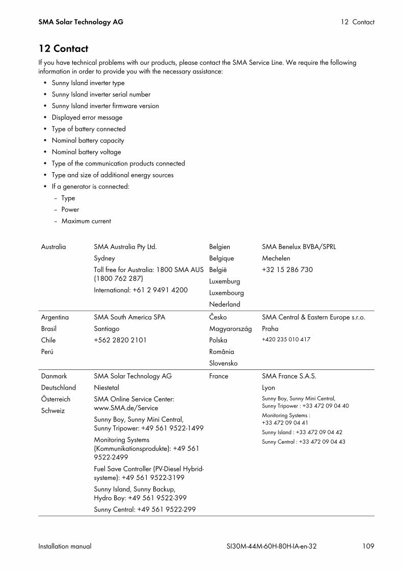
SMA Solar Technology AG 12 Contact
Installation manual SI30M-44M-60H-80H-IA-en-32 109
12 ContactIf you have technical problems with our products, please contact the SMA Service Line. We require the following information in order to provide you with the necessary assistance:
• Sunny Island inverter type• Sunny Island inverter serial number• Sunny Island inverter firmware version• Displayed error message• Type of battery connected• Nominal battery capacity• Nominal battery voltage• Type of the communication products connected• Type and size of additional energy sources• If a generator is connected:
– Type– Power– Maximum current
Australia SMA Australia Pty Ltd.SydneyToll free for Australia: 1800 SMA AUS (1800 762 287)International: +61 2 9491 4200
BelgienBelgiqueBelgiëLuxemburgLuxembourgNederland
SMA Benelux BVBA/SPRLMechelen+32 15 286 730
ArgentinaBrasilChilePerú
SMA South America SPASantiago+562 2820 2101
ČeskoMagyarországPolskaRomâniaSlovensko
SMA Central & Eastern Europe s.r.o.Praha+420 235 010 417
DanmarkDeutschlandÖsterreichSchweiz
SMA Solar Technology AGNiestetalSMA Online Service Center: www.SMA.de/ServiceSunny Boy, Sunny Mini Central, Sunny Tripower: +49 561 9522-1499Monitoring Systems (Kommunikationsprodukte): +49 561 9522-2499Fuel Save Controller (PV-Diesel Hybrid- systeme): +49 561 9522-3199Sunny Island, Sunny Backup, Hydro Boy: +49 561 9522-399Sunny Central: +49 561 9522-299
France SMA France S.A.S.LyonSunny Boy, Sunny Mini Central, Sunny Tripower : +33 472 09 04 40Monitoring Systems : +33 472 09 04 41Sunny Island : +33 472 09 04 42Sunny Central : +33 472 09 04 43

12 Contact SMA Solar Technology AG
110 SI30M-44M-60H-80H-IA-en-32 Installation manual
EspañaPortugal
SMA Ibérica Tecnología Solar, S.L.U.Barcelona+34 935 63 50 99
India SMA Solar India Pvt. Ltd.Mumbai+91 22 61713888
South Africa SMA Solar Technology South Africa Pty Ltd.Centurion (Pretoria)08600 SUNNY (08600 78669)International: +27 (12) 622 3000
ΕλλάδαΚύπροςKıbrısБългария
SMA Hellas AEΑθήνα+30 210 9856666
Italia SMA Italia S.r.l.Milano+39 02 8934-7299
United Kingdom SMA Solar UK Ltd.Milton Keynes+44 1908 304899
SMA Solar (Thailand) Co., Ltd.
+66 2 670 6999
대한민국 SMA Technology Korea Co., Ltd.서울+82-2-520-2666
SMA Middle East LLC
+971 2 234-6177
Other countries International SMA Service LineNiestetalToll free worldwide: 00800 SMA SERVICE (+800 762 7378423)
!


www.SMA-Solar.comSMA Solar Technology