Installation Manual -...
44
R EPA CERTIFIED WOODBURNING FIREPLACE Fire Risk. WARNING For use with solid wood fuel only. Other fuels may overfire and generate poisonous gases (i.e. carbon monoxide). O-T L Tested and Listed by Portland Oregon USA OMNI-Test Laboratories, Inc. C US Model(s): Installation Manual Installation and Fireplace Setup WARNING HOT SURFACES! Glass and other surfaces are hot during operation AND cool down. Hot glass will cause burns. • DO NOT touch glass until it is cooled • NEVER allow children to touch glass • Keep children away • CAREFULLY SUPERVISE children in same room as fireplace. • Alert children and adults to hazards of high temperatures. High temperatures may ignite clothing or other flammable materials. • Keep clothing, furniture, draperies and other flammable materials away. INSTALLER: Leave this manual with party responsible for use and operation. OWNER: Retain this manual for future reference. PIONEER-II-BK NOTICE: DO NOT discard this manual! • DO NOT store or use gasoline or other flam- mable vapors and liquids in the vicinity of this or any other appliance. • DO NOT overfire. Overfiring will void your warranty. • Comply with all minimum clearances to com- bustibles as specified. Failure to comply may cause house fire. WARNING: If the information in these instructions is not followed exactly, a fire or explosion may result causing property damage, personal injury, or death. Installation and s ervice of this appliance should be performed b y 1 Quadra-Fire • PIONEER II • 4181-901 Installation Manual • Rev E • 08/17
Transcript of Installation Manual -...
R
EPA CERTIFIED WOODBURNING FIREPLACE
Fire Risk.
WARNING
For use with solid wood fuel only.Other fuels may overfire and generate poisonous gases (i.e. carbon monoxide).
O-T LTested and Listed by
PortlandOregon USA
OMNI-Test Laboratories, Inc.C US
Model(s):
Installation ManualInstallation and Fireplace Setup
WARNINGHOT SURFACES! Glass and other surfaces are hot during operation AND cool down.
Hot glass will cause burns.• DO NOT touch glass until it is cooled• NEVER allow children to touch glass• Keep children away
• CAREFULLY SUPERVISE children in same room as fireplace.
• Alert children and adults to hazards of high temperatures.
High temperatures may ignite clothing or other flammable materials.• Keep clothing, furniture, draperies and other flammable
materials away.
INSTALLER: Leave this manual with party responsible for use and operation.OWNER: Retain this manual for future reference.
PIONEER-II-BK
NOTICE: DO NOT discard this manual!
• DO NOT store or use gasoline or other flam-mable vapors and liquids in the vicinity of this or any other appliance.
• DO NOT overfire. Overfiring will void your warranty.
• Comply with all minimum clearances to com-bustibles as specified. Failure to comply may cause house fire.
WARNING: If the information in these instructions is not followed exactly, a fire or explosion may result causing property damage, personal injury, or death.
Installation and service of this appliance should be performed by
1Quadra-Fire • PIONEER II • 4181-901 Installation Manual • Rev E • 08/17
Safety Alert Key:• DANGER! Indicates a hazardous situation which, if not avoided will result in death or serious injury.• WARNING! Indicates a hazardous situation which, if not avoided could result in death or serious injury.• CAUTION! Indicates a hazardous situation which, if not avoided, could result in minor or moderate injury.• NOTICE: Indicates practices which may cause damage to the fireplace or to property.
Table of Contents1 Product Specific & Important Safety Information
A. Appliance Certification/Mobile Home Approved 4B. Glass Specifications 5C. Non-Combustible Materials 5D. Combustible Materials 5E. Electrical Codes 5
2 Getting Started A. Typical Fireplace System 6B. Design and Installation Considerations 7
1. Selecting Fireplace Locations 72. Locating Fireplace & Chimney 8
C. Tools and Supplies Needed 9D. Inspect Fireplace and Components 9E. Fireplace System Requirements 9
3 Framing and Clearances A. Fireplace Dimensions 10B. Clearances 11
1. Minimum Clearances 12C. Construct the Chase 13D. Frame the Fireplace 14E. Secure and Level the Fireplace 14F. Protective Metal Hearth Strips 15G. Facing Material 15H. Outside Air Kit 16I. Heat Zone Kit (Optional) 18
4 Electrical Wiring 21
5 Chimney and Termination Requirements A. Chimney Requirements 22B. Offsets/Returns 23C. Termination Requirements 24
6 Chimney Installation A. Typical Chimney System 25B. Assemble Chimney Sections 26C. Install Chimney Air kit (CAK4A) 26D. Secure Offset/Return 28E. Install Ceiling Firestops 28F. Install Attic Insulation Shield 29G. Roof Penetration 30H. Manufactured Home Installation 30I. Install Chase/Chase Top 31J. Termination Cap Requirements 32K. Install Termination Cap 32
7 Finishing A. Template 34B Finish the Wall 34
1. Stone, Brick Finish 342. Tile, Granite, Marble Finish 34
C. Mantel and Wall Projections 35D. Finishing the Hearth Extension 35E. Non-Combustible Sealant Material 37
8 Fireplace Setup A. Firebrick Placement 38B. Baffle and Blanket Placement 39
9 Reference Materials A. Chimney Components 40
2 Quadra-Fire • PIONEER II • 4181-901 Installation Manual • Rev E • 08/17
►
►

Customer:Lot/Address
Model (circle one): Pioneer-II-BK
Fireplace Install Section 3 (Pg.10) YES IF NO, WHY?Verified that the chase is insulated and sealed. (Pg. 13)Required non-combustible board is installed. (Pg. 15)Verified clearances to combustibles. (Pg. 11)Fireplace is leveled and secured. (Pg. 14)Hearth extension size/height decided. (Pg. 14 & 35)Outside air kit installed. (Pg. 16)Optional Heat Zone has been installed by a qualified service technician. (Pg. 18)
Chimney Section 5 (Pg. 22)Chimney configuration complies with diagrams.Chimney installed, locked and secured in place with proper clearance.Chimney air kit installed.Firestops installed.Attic insulation shield installed.Roof flashing/storm collar installed and sealed.Terminations installed and sealed.
Electrical Section 4 (Pg. 21)Switch wires properly installed.
Finishing Section 7 (Pg. 34)Combustible materials not installed in non-combustible areas.Verified all clearances meet installation manual requirements.Mantels and wall projections comply with installation manual requirements.Protective hearth strips and hearth extension installed per manual requirements.
Fireplace Setup Section 8 (Pg. 38)All packaging and protective materials removed.Firebrick, baffle and ceramic blanket installed correctly.Facia and door properly installed.
All packaging materials are removed from inside/under the fireplace.
Hearth & Home Technologies recommends the following:• Photographing the installation and copying this checklist for your file.• That this checklist remain visible at all times on the fireplace until the installation is complete.
Comments communicated to party responsible
Part 4181-982 • Rev A • 7/1/16
ATTENTION INSTALLER:Follow this Standard Work Checklist
This standard work checklist is to be used by the installer in conjuction with, not instead of, the instructions contained in this installation manual.
Date Installed:Location of Fireplace:Installer:Dealer/Distributor Phone #Serial #:
__________________________ by ______________________on _________(Builder/Gen. Contractor) (Installer) (Date)
Comments: Further description of the issues, who is responsible (Installer/Builder/Other Trades, etc.) and corrective action needed: _________________________________________________________________________________________________
WARNING! Risk of Fire or Explosion! Failure to install fireplace acording to these instructions can lead to a fire or explosion.
Manual bag and all of its contents are removed from inside/under the fireplace and given to the party responsible for use and operation.
________________________________________________________________________________________________________________________________________________________________________________________________________________
3Quadra-Fire • PIONEER II • 4181-901 Installation Manual • Rev E • 08/17
1 Product Specific & Important Safety Information 1 Product Specific & Important Safety Information
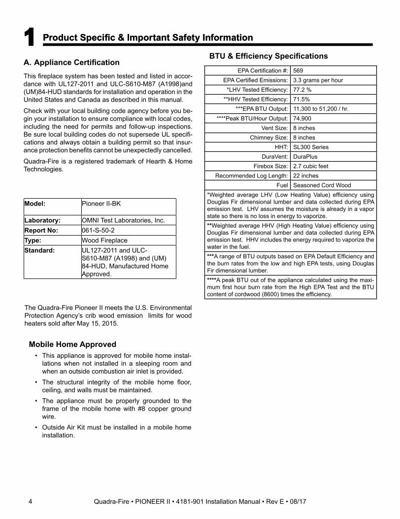
A. Appliance CertificationThis fireplace system has been tested and listed in accor-dance with UL127-2011 and ULC-S610-M87 (A1998)and (UM)84-HUD standards for installation and operation in the United States and Canada as described in this manual.
Check with your local building code agency before you be-gin your installation to ensure compliance with local codes, including the need for permits and follow-up inspections. Be sure local building codes do not supersede UL specifi-cations and always obtain a building permit so that insur-ance protection benefits cannot be unexpectedly cancelled.
Quadra-Fire is a registered trademark of Hearth & Home Technologies.
Model: Pioneer II-BK
Laboratory: OMNI Test Laboratories, Inc.Report No: 061-S-50-2Type: Wood FireplaceStandard: UL127-2011 and ULC-
S610-M87 (A1998) and (UM) 84-HUD, Manufactured Home Approved.
BTU & Efficiency Specifications
The Quadra-Fire Pioneer II meets the U.S. Environmental Protection Agency’s crib wood emission limits for wood heaters sold after May 15, 2015.
EPA Certification #: 569EPA Certified Emissions: 3.3 grams per hour
*LHV Tested Efficiency: 77.2 %**HHV Tested Efficiency: 71.5%
***EPA BTU Output: 11,300 to 51,200 / hr.****Peak BTU/Hour Output: 74,900
Vent Size: 8 inchesChimney Size: 8 inches
HHT: SL300 SeriesDuraVent: DuraPlus
Firebox Size: 2.7 cubic feetRecommended Log Length: 22 inches
Fuel Seasoned Cord Wood*Weighted average LHV (Low Heating Value) efficiency using Douglas Fir dimensional lumber and data collected during EPA emission test. LHV assumes the moisture is already in a vapor state so there is no loss in energy to vaporize.**Weighted average HHV (High Heating Value) efficiency using Douglas Fir dimensional lumber and data collected during EPA emission test. HHV includes the energy required to vaporize the water in the fuel.***A range of BTU outputs based on EPA Default Efficiency and the burn rates from the low and high EPA tests, using Douglas Fir dimensional lumber.****A peak BTU out of the appliance calculated using the maxi-mum first hour burn rate from the High EPA Test and the BTU content of cordwood (8600) times the efficiency.
Mobile Home Approved • This appliance is approved for mobile home instal-
lations when not installed in a sleeping room and when an outside combustion air inlet is provided.
• The structural integrity of the mobile home floor, ceiling, and walls must be maintained.
• The appliance must be properly grounded to the frame of the mobile home with #8 copper ground wire.
• Outside Air Kit must be installed in a mobile home installation.
4 Quadra-Fire • PIONEER II • 4181-901 Installation Manual • Rev E • 08/17
E. Electrical Codes
NOTICE: This fireplace must be electrically wired and grounded in accordance with local codes or, in the absence of local codes, with National Electric Code ANSI/NFPA 70-latest edition or the Canadian Electric Code CSA C22.1.
• A 110-120 VAC circuit for this product must be protected with ground-fault circuit-interrupter protection, in compliance with the applicable electrical codes, when it is installed in damp locations.
WARNING! Improper installation, adjustment, alteration, service or maintenance can cause injury or property dam-age.
D. Combustible Materials• Materials made of or surfaced with any of the following
materials:- Wood - Compressed paper- Plant fibers - Plastic- Plywood/OSB - Sheet rock (drywall)
• Any material that can ignite and burn; flame proofed or not, plastered or un-plastered
C. Non-Combustible Materials• Materials which will not ignite and burn, composed of
any combination of the following:- Steel - Iron- Brick - Tile- Concrete - Slate- Glass - Plasters
• Materials reported as passing ASTM E 136, Standard Test Method for Behavior of Metals, in a Vertical Tube Furnace at 750° C
B. Glass SpecificationsThis fireplace is equipped with 5 mm ceramic glass. Re-place glass only with 5 mm ceramic glass. Please contact your dealer for replacement glass.
NOTICE: This installation must conform with local codes. In the absence of local codes you must comply with the UL127-2011, (UM) 84-HUD and NFPA211 in the U.S.A. and the ULC 610-M87 (A1998) and CAN/CSA-B365 Installation Codes in Canada.
WARNING! Risk of Fire! Hearth & Home Technologies disclaims any responsibility for, and the warranty and agen-cy listing will be voided by the following actions.DO NOT:• install or operate damaged fireplace• modify fireplace• install other than as instructed by Hearth & Home
Technologies• operate the fireplace without fully assembling all
components• overfire• install any gas log set• install any component not approved by Hearth & Home
Technologies• install parts or components not Listed or approvedImproper installation, adjustment, alteration, service or maintenance can cause injury or property damage. For assistance or additional information, consult a qualified installer, service agency or your dealer.
WARNING! Risk of Fire! Hearth & Home Technologies is not responsible for
discoloration, cracking or other material failures of finishing materials due to heat exposure or smoke.
• Choose finishing materials carefully.
5Quadra-Fire • PIONEER II • 4181-901 Installation Manual • Rev E • 08/17
2 Getting Started
A. Typical Fireplace System
Figure 2.1 Typical Fireplace System
Non-combustibleroof flashing maintainsminimum clearancearound chimney
Additional lateralsupport for chimneyabove roof (or enclosedin chase) if needed
Enclosed space aboveand around fireplace
Support strapson rafter supportschimney (not shown)
Outsidecombustion air
Outsidecombustion air
Termination Cap
Chimney penetrates roof preferably without affectingroof rafters
Storm Collar
Offset/Return (with hanger straps)
Attic insulation shield must be used here to keep insulation away from chimney if attic is insulated
Framing headed off in ceiling joists
Mantel
Decorative facingand trim
Factory-built fireplace
Chimney system
Combustible framing/headeron top of V-shaped standoffs (spacers)
Hearth extension
Protective metalhearth strip(s)
Chimney Air kit required for SL chimney
Ceiling firestop on floor of attic
6 Quadra-Fire • PIONEER II • 4181-901 Installation Manual • Rev E • 08/17
D
CA
E
F
AH
GB
A
B
B
AI
In an exterior chase or projecting into a garage
Across a corner
Along a wall
As a room divider
24 in. (610mm)
24 in. (610mm)
24 in. (610mm)
48 in. (1219mm)
*If interior of chase will be drywalled, add the thickness to this measurement.
°Faceplate to sidewall
24 in. (610mm)
I
A
*
*
*
*
Figure 2.2 Fireplace Locations
NOTICE:• Illustrations and photos reflect typical installations and
are FOR DESIGN PURPOSES ONLY.• Illustrations/diagrams are not drawn to scale.• Actual installation/appearance may vary due to individual
design preference.• Hearth & Home Technologies reserves the right to alter
its products.
NOTICE: In addition to these framing dimensions, also reference the following section:
• Clearances (Section 3).
NOTICE: A minimum 1 in. air clearance at the back and a minimum 1 in. air clearance to the sides of the fireplace assembly must be maintained.Chimney sections at any level require a 2 in. mini-mum air space clearance between the framing and chimney sections.
B. Design and Installation Considerations
NOTICE: Check building codes prior to installation.
• Installation MUST comply with local, regional, state and national codes and regulations.
• Consult insurance carrier, local building inspector, fire officials or authorities having jurisdiction over restrictions, installation inspection and permits.
1. Selecting Fireplace LocationsThis fireplace may be used as a room divider, installed along a wall, across a corner or used in an exterior chase. See Figure 2.2.
Locating the fireplace in a basement, near frequently opened door, central heat outlets or returns, or other loca-tions of considerable air movement can affect the perfor-mance.
Outside air must be used for combustion. The Pioneer II comes equipped with an outside air inlet to feed combus-tion air from outside the home, along with an outside air termination cap; the rigid metal duct is required but not supplied. Consideration should be given to these factors before deciding on a location.
Model # A B C D E F G H I
Pioneer (dimensions for finished walls)
in. 42-1/2 16 89-1/2 63-5/16 22-7/16 44-3/4 14-1/16 56-9/16 54-1/2
mm 1080 406 2273 1608 570 1137 357 1437 1384
7Quadra-Fire • PIONEER II • 4181-901 Installation Manual • Rev E • 08/17
2. Locating Fireplace & Chimney
Location of the fireplace and chimney will affect perfor-mance.
• Install within the warm airspace enclosed by the building envelope. This helps to produce more draft, especially during lighting and die-down of the fire.
• Penetrate the highest part of the roof. This minimizes the effects of wind loading.
• Locate termination cap away from trees, adjacent structures, uneven roof lines and other obstructions.
• Minimize the use of chimney offsets. • Consider the fireplace location relative to floor and ceiling
and attic joists.• Take into consideration the termination requirements in
Sections 5 and 6.
Marginal Location:• Below peak
Location NOT recommended:• Not the highest point of the roof• Wind loading possible
Multi-level Roofs
Windward
Leeward
Recommended Location:• Above peak
Recommended:• Insulated exterior chase
in cooler climates
Recommended Location:• Above peak• Inside heated space
Location NOT recommended:• Too close to tree• Below adjacent structure• Lower roof line• Avoid outside wall
Marginal Location:• Wind loading possible
Locating the appliance in a basement or in a location of considerable air movement/negative pressure can cause intermittent smoke spillage from appliance. DO NOT locate appliance near: -Frequently Opened Doors -Central Heat Outlets or Returns
Figure 2.3 Recommended Chimney Locations
• Install the outside air kit with the intake facing prevailing winds during the heating season.
• Ensure adequate outdoor air for all combustion appliances and exhaust equipment.
• Ensure furnace and air conditioning return vents are not located in the immediate vicinity of the fireplace.
• Avoid installing the fireplace near doors, walkways or small isolated spaces.
• Recessed lighting should be a “sealed can” design.• Attic hatches weather stripped or sealed.• Attic mounted duct work and air handler joints and seams
taped or sealed.
8 Quadra-Fire • PIONEER II • 4181-901 Installation Manual • Rev E • 08/17
C. Tools and Supplies NeededBefore beginning the installation be sure the following tools and building supplies are available:
Reciprocating saw Framing material
Pliers Non-combustible sealant
Hammer Gloves
Phillips screwdriver Framing square
Flat blade screwdriver Electric drill and bits
Plumb line Safety glasses
Level Tape measure
1/2-3/4 in. length, #6 or #8 self-drilling screws
Misc. screws and nails
D. Inspect Fireplace and Components
WARNING! Risk of Fire and/or Explosion! Damaged parts could impair safe operation. DO NOT install dam-aged, incomplete or substitute components. Keep fire-place dry.
• Remove fireplace and components from packaging and inspect for damage.
• Vent system components are shipped in separate packages.
• Report to your dealer any parts damaged in shipment.• Read all the instructions before starting the
installation. Follow these instructions carefully during the installation to ensure maximum safety and benefit.
E. Fireplace System RequirementsThe fireplace system requirements consist of the follow-ing:
• Fireplace- Firebrick (included with fireplace)- Door (included with fireplace)- Non-combustible facing material (included with
fireplace)- Protective metal hearth strip (included with fireplace)- Hearth Extension
• Outside Air System (hood and collars included with fireplace)
• Fascia (included with fireplace)• Chimney System
- Chimney air kit (included with fireplace, required with SL300 series chimney)
- Attic Insulation Shield (included with fireplace)• Non-combustible finish material
Optional components include:• Lintel Bar• Heat Zone Kit • Template• Outside Air Elbow Kit
9Quadra-Fire • PIONEER II • 4181-901 Installation Manual • Rev E • 08/17
3 Framing and Clearances
A. Fireplace Dimensions
Figure 3.1 Fireplace Dimensions
584
3[76]
10 Quadra-Fire • PIONEER II • 4181-901 Installation Manual • Rev E • 08/17
B. ClearancesWARNING! Risk of Fire!
You must comply with all minimum air space clearances to combustibles as specified in Figure 3.2. DO NOT pack required air spaces with insulation or other materials. Framing or finishing material used on the front of, or in front of, the fireplace closer than the minimums listed must be constructed entirely of non-combustible materials (i.e., steel studs, concrete board, etc.). Failure to comply may cause fire.
Figure 3.2 Clearances to Combustible Materials
2 in. (51 mm) min.
Attic Insulation
Shield
Ceiling Firestop
(ceiling)
(roof)
(attic)
(ceiling)
Ceiling Firestop Offset/Return with hanger straps
Storm Collar
Roof Flashing
2 in. (51 mm) min.
2 in. min.(51 mm)
Must have 2 in. (51 mm)minimum clearance
to header
2 in. (51 mm) min.
2 in. (51 mm) min.
2 in. (51 mm) min.
1 in. (25mm) to side of appliance(except at nailing flanges where it is 1/2 in. [13 mm])
1 in. (25 mm) to backof appliance
0 in.to floor
0 in. to levelof standoffs
2 in.(51 mm)
min. 36 in. (914 mm)
standoffs to ceiling
Chimney air kit required with SL chimney
11Quadra-Fire • PIONEER II • 4181-901 Installation Manual • Rev E • 08/17
1. Minimum Clearances
Position combustible/ non-combustible mantel60 in. (1524 mm) from base of fireplace
12 in.(305 mm)
44 in.(1118 mm)
24 in.*(610 mm) 48-1/2 in.
(1232 mm)
42-1/2in.(1080 mm)
The �nished cavity depth must be no less than 24 in. (610 mm) from the �nished backwall to the outside of front wall framing.
2 x 4s must be used for the header and framing above the header to maintain pipe clearances.
Double studs to catch non-combustible board and wall facing material.
*If interior of chase will be drywalled, add the thickness to this measurement.
12 in.(305 mm)
When installing the outside air with an elbow/bend, allow a minimum cavity of 12 in. (305mm)
14 1/2 in. (368 mm) for SL300 Chimney16 in. (406 mm) for DuraPlus Chimney
Figure 3.3 Framing the Fireplace
WITHIN ENCLOSURE AREAFireplace to backwall 1 in. (25 mm)Fireplace to sidewall 1 in. (25 mm)Duct boots to framing 0 in. (0 mm)Top standoffs to header 0 in. (0 mm)Door opening to sidewall 22-7/8 in. (581 mm)
EXPOSED SURFACESFaceplate to sidewall 16 in. (406 mm)Heat zone air grills to ceiling 12 in. (305 mm)
MANTELNon-combustible mantel (Non-combustible framing materials above the fireplace to ceiling) 46 in. (1168 mm)Combustible mantel (Combustible framing materials above the fireplace to ceiling) 60 in. (1524 mm)Maximum mantel depth 12 in. (305 mm)
12 Quadra-Fire • PIONEER II • 4181-901 Installation Manual • Rev E • 08/17
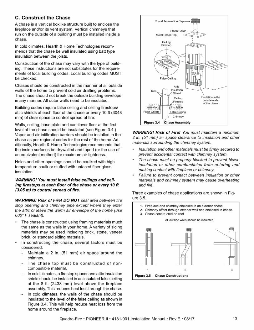
C. Construct the ChaseA chase is a vertical boxlike structure built to enclose the fireplace and/or its vent system. Vertical chimneys that run on the outside of a building must be installed inside a chase.
In cold climates, Hearth & Home Technologies recom-mends that the chase be well insulated using batt type insulation between the joists.
Construction of the chase may vary with the type of build-ing. These instructions are not substitutes for the require-ments of local building codes. Local building codes MUST be checked.
Chases should be constructed in the manner of all outside walls of the home to prevent cold air drafting problems. The chase should not break the outside building envelope in any manner. All outer walls need to be insulated.
Building codes require false ceiling and ceiling firestops/attic shields at each floor of the chase or every 10 ft (3048 mm) of clear space to control spread of fire.
Walls, ceiling, base plate and cantilever floor at the first level of the chase should be insulated (see Figure 3.4.) Vapor and air infiltration barriers should be installed in the chase as per regional codes for the rest of the home. Ad-ditionally, Hearth & Home Technologies recommends that the inside surfaces be drywalled and taped (or the use of an equivalent method) for maximum air tightness.
Holes and other openings should be caulked with high temperature caulk or stuffed with unfaced fiber glass insulation.
Ceiling Firestop
Metal Chase Top
Round Termination Cap
False Ceiling
Insulation in the outside walls of the chase
Attic Insulation
Shield
Chimney
Ceiling Firestop
Tabs
False Ceiling False Ceiling Insulation Insulation
Storm Collar
Figure 3.4 Chase Assembly
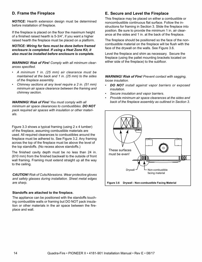
1 2 3
All outside walls should be insulated.
Figure 3.5 Chase Constructions
1. Fireplace and chimney enclosed in an exterior chase. 2. Chimney offset through exterior wall and enclosed in chase. 3. Chase constructed on roof.
• The chase is constructed using framing materials much the same as the walls in your home. A variety of siding materials may be used including brick, stone, veneer brick, or standard siding materials.
• In constructing the chase, several factors must be considered:- Maintain a 2 in. (51 mm) air space around the
chimney.- The chase top must be constructed of non-
combustible material.- In cold climates, a firestop spacer and attic insulation
shield should be installed in an insulated false ceiling at the 8 ft. (2438 mm) level above the fireplace assembly. This reduces heat loss through the chase.
- In cold climates, the walls of the chase should be insulated to the level of the false ceiling as shown in Figure 3.4. This will help reduce heat loss from the home around the fireplace.
Three examples of chase applications are shown in Fig-ure 3.5.
WARNING! You must install false ceilings and ceil-ing firestops at each floor of the chase or every 10 ft (3.05 m) to control spread of fire.
WARNING! Risk of Fire! DO NOT seal area between fire stop opening and chimney pipe except where they enter the attic or leave the warm air envelope of the home (use 600° F sealant).
WARNING! Risk of Fire! You must maintain a minimum 2 in. (51 mm) air space clearance to insulation and other materials surrounding the chimney system.• Insulation and other materials must be firmly secured to
prevent accidental contact with chimney system.• The chase must be properly blocked to prevent blown
insulation or other combustibles from entering and making contact with fireplace or chimney.
• Failure to prevent contact between insulation or other materials and chimney system may cause overheating and fire.
13Quadra-Fire • PIONEER II • 4181-901 Installation Manual • Rev E • 08/17
D. Frame the Fireplace
NOTICE: Hearth extension design must be determined before installation of fireplace.
If the fireplace is placed on the floor the maximum height of a finished raised hearth is 5-3/4”, if you want a higher raised hearth the fireplace must be placed on a platform.
NOTICE: Wiring for fans must be done before framed enclosure is completed. If using a Heat Zone Kit, it also must be installed before enclosure is complete.
WARNING! Risk of Fire! You must comply with all minimum air space clearances to combustibles. DO NOT pack required air spaces with insulation or other materi-als.
WARNING! Risk of Fire! Comply with all minimum clear-ances specified.• A minimum 1 in. (25 mm) air clearance must be
maintained at the back and 1 in. (25 mm) to the sides of the fireplace assembly.
• Chimney sections at any level require a 2 in. (51 mm) minimum air space clearance between the framing and chimney section.
Figure 3.3 shows a typical framing (using 2 x 4 lumber) of the fireplace, assuming combustible materials are used. All required clearances to combustibles around the fireplace must be adhered to. See Figure 3.2. Any framing across the top of the fireplace must be above the level of the top standoffs. (No recess above standoffs.)
The finished cavity depth must be no less than 24 in. (610 mm) from the finished backwall to the outside of front wall framing. Framing must extend straight up all the way to the ceiling.
CAUTION! Risk of Cuts/Abrasions. Wear protective gloves and safety glasses during installation. Sheet metal edges are sharp.
WARNING! Risk of Fire! Prevent contact with sagging, loose insulation. • DO NOT install against vapor barriers or exposed
insulation.• Secure insulation and vapor barriers.• Provide minimum air space clearances at the sides and
back of the fireplace assembly as outlined in Section 3.
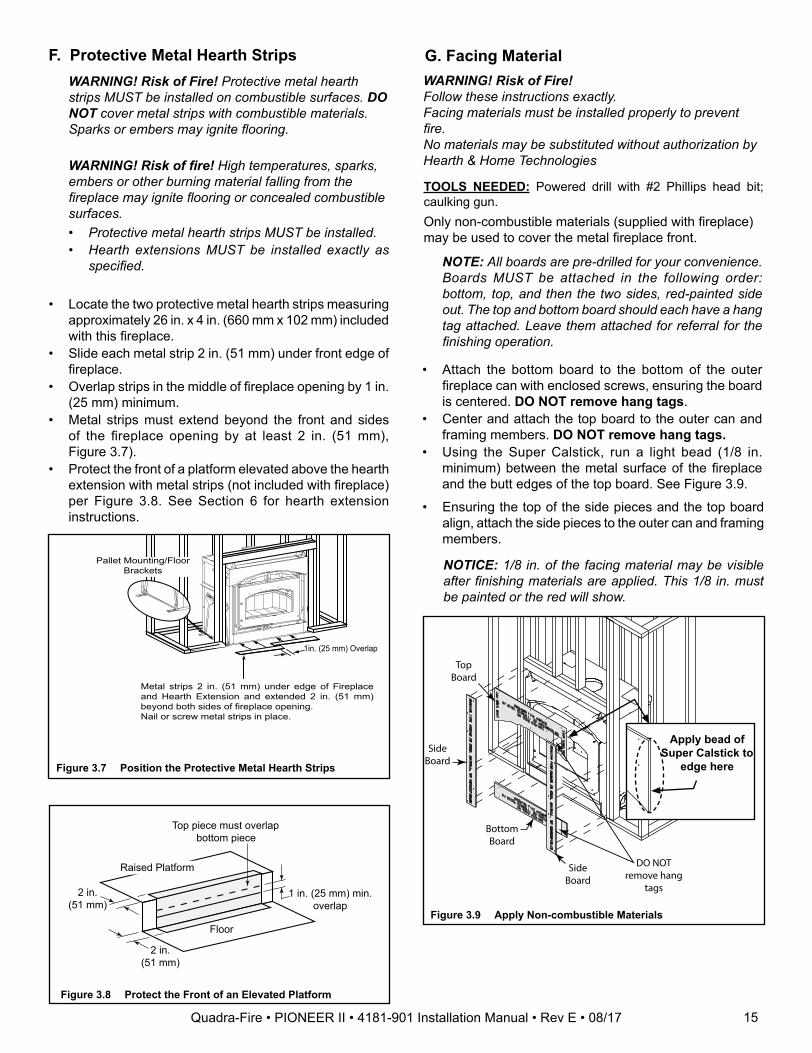
E. Secure and Level the FireplaceThis fireplace may be placed on either a combustible or noncombustible continuous flat surface. Follow the in-structions for framing in Section 3. Slide the fireplace into position. Be sure to provide the minimum 1 in. air clear-ance at the sides and 1 in. at the back of the fireplace.
The fireplace should be positioned so the face of the non-combustible material on the fireplace will be flush with the face of the drywall on the walls. See Figure 3.6.
Level the fireplace and shim as necessary. Secure the fireplace (using the pallet mounting brackets located on either side of the fireplace) to the subfloor.
These surfaces must be even!
Drywall Non-combustiblefacing material
Figure 3.6 Drywall - Non-combustible Facing Material
Standoffs are attached to the fireplace.The appliance can be positioned with the standoffs touch-ing combustible walls or framing but DO NOT pack insula-tion or other materials in the air space between the fire-place and wall.
14 Quadra-Fire • PIONEER II • 4181-901 Installation Manual • Rev E • 08/17
1in. (25 mm) Overlap
Metal strips 2 in. (51 mm) under edge of Fireplace and Hearth Extension and extended 2 in. (51 mm) beyond both sides of fireplace opening.Nail or screw metal strips in place.
Pallet Mounting/Floor Brackets
Raised Platform
Floor
2 in.(51 mm)
1 in. (25 mm) min.overlap
2 in.(51 mm)
Top piece must overlapbottom piece
Figure 3.8 Protect the Front of an Elevated Platform
F. Protective Metal Hearth Strips
Figure 3.7 Position the Protective Metal Hearth Strips
• Locate the two protective metal hearth strips measuring approximately 26 in. x 4 in. (660 mm x 102 mm) included with this fireplace.
• Slide each metal strip 2 in. (51 mm) under front edge of fireplace.
• Overlap strips in the middle of fireplace opening by 1 in. (25 mm) minimum.
• Metal strips must extend beyond the front and sides of the fireplace opening by at least 2 in. (51 mm), Figure 3.7).
• Protect the front of a platform elevated above the hearth extension with metal strips (not included with fireplace) per Figure 3.8. See Section 6 for hearth extension instructions.
WARNING! Risk of Fire! Protective metal hearth strips MUST be installed on combustible surfaces. DO NOT cover metal strips with combustible materials. Sparks or embers may ignite flooring.
WARNING! Risk of fire! High temperatures, sparks, embers or other burning material falling from the fireplace may ignite flooring or concealed combustible surfaces.• Protective metal hearth strips MUST be installed.• Hearth extensions MUST be installed exactly as
specified.
WARNING! Risk of Fire!Follow these instructions exactly.Facing materials must be installed properly to prevent fire.No materials may be substituted without authorization by Hearth & Home Technologies
G. Facing Material
TOOLS NEEDED: Powered drill with #2 Phillips head bit; caulking gun.Only non-combustible materials (supplied with fireplace) may be used to cover the metal fireplace front.
NOTE: All boards are pre-drilled for your convenience. Boards MUST be attached in the following order: bottom, top, and then the two sides, red-painted side out. The top and bottom board should each have a hang tag attached. Leave them attached for referral for the finishing operation.
• Attach the bottom board to the bottom of the outer fireplace can with enclosed screws, ensuring the board is centered. DO NOT remove hang tags.
• Center and attach the top board to the outer can and framing members. DO NOT remove hang tags.
• Using the Super Calstick, run a light bead (1/8 in. minimum) between the metal surface of the fireplace and the butt edges of the top board. See Figure 3.9.
• Ensuring the top of the side pieces and the top board align, attach the side pieces to the outer can and framing members.
Figure 3.9 Apply Non-combustible Materials
Side Board
Bottom Board
Side Board
Top Board
DO NOT remove hang
tags
Apply bead of Super Calstick to
edge here
NOTICE: 1/8 in. of the facing material may be visible after finishing materials are applied. This 1/8 in. must be painted or the red will show.
15Quadra-Fire • PIONEER II • 4181-901 Installation Manual • Rev E • 08/17
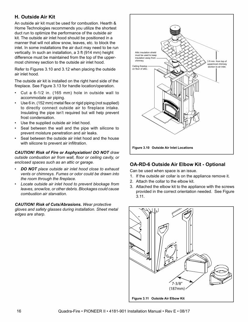
H. Outside Air KitAn outside air kit must be used for combustion. Hearth & Home Technologies recommends you utilize the shortest duct run to optimize the performance of the outside air kit. The outside air inlet hood should be positioned in a manner that will not allow snow, leaves, etc. to block the inlet. In some installations the air duct may need to be run vertically. In such an installation, a 3 ft (914 mm) height difference must be maintained from the top of the upper-most chimney section to the outside air inlet hood.
Refer to Figures 3.10 and 3.12 when placing the outside air inlet hood.
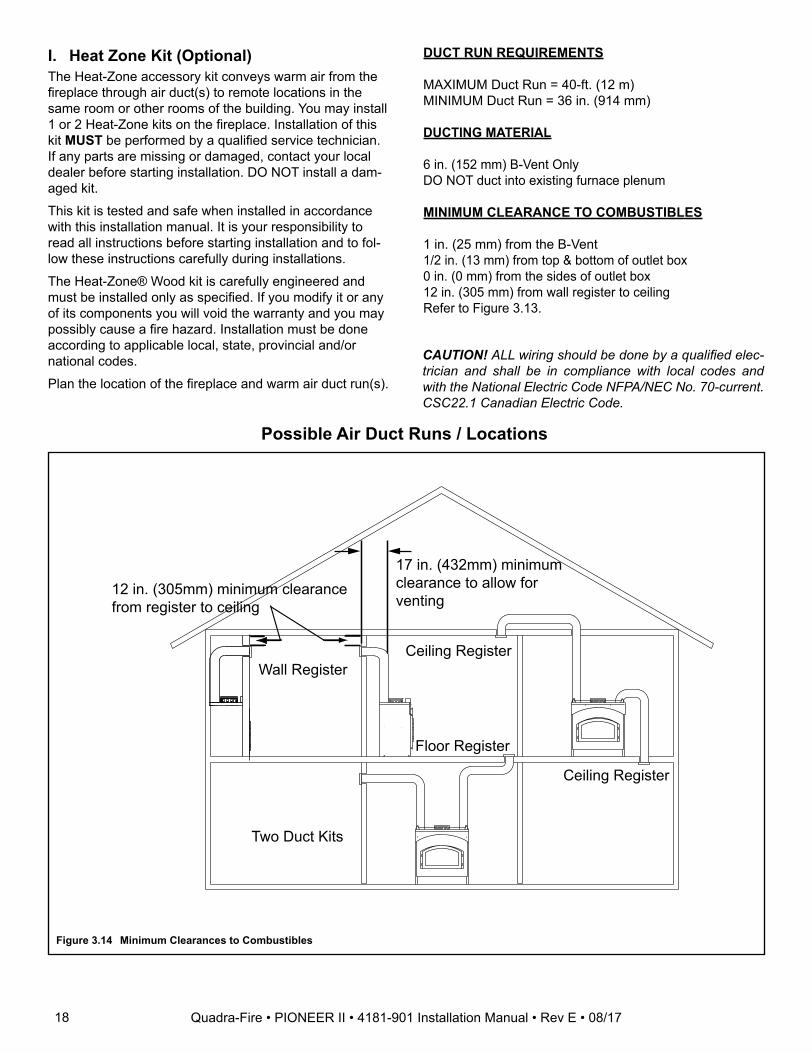
The outside air kit is installed on the right hand side of the fireplace. See Figure 3.13 for handle location/operation.
• Cut a 6-1/2 in. (165 mm) hole in outside wall to accommodate air piping.
• Use 6 in. (152 mm) metal flex or rigid piping (not supplied) to directly connect outside air to fireplace intake. Insulating the pipe isn’t required but will help prevent frost condensation.
• Use the supplied outside air inlet hood.• Seal between the wall and the pipe with silicone to
prevent moisture penetration and air leaks.• Seal between the outside air inlet hood and the house
with silicone to prevent air infiltration.
CAUTION! Risk of Cuts/Abrasions. Wear protective gloves and safety glasses during installation. Sheet metal edges are sharp.
CAUTION! Risk of Fire or Asphyxiation! DO NOT draw outside combustion air from wall, floor or ceiling cavity, or enclosed spaces such as an attic or garage. • DO NOT place outside air inlet hood close to exhaust
vents or chimneys. Fumes or odor could be drawn into the room through the fireplace.
• Locate outside air inlet hood to prevent blockage from leaves, snow/ice, or other debris. Blockages could cause combustion air starvation.
Figure 3.10 Outside Air Inlet Locations
Attic insulation shieldmust be used to keepinsulation away fromchimney.
Ceiling firestopon floor of attic.
3 ft min. from top ofuppermost chimney section to air inlet.
OA-RD-6 Outside Air Elbow Kit - OptionalCan be used when space is an issue.1. If the outside air collar is on the appliance remove it.2. Attach the collar to the elbow kit.3. Attached the elbow kit to the appliance with the screws
provided in the correct orientation needed. See Figure 3.11.
7-3/8”(187mm)
Figure 3.11 Outside Air Elbow Kit
16 Quadra-Fire • PIONEER II • 4181-901 Installation Manual • Rev E • 08/17
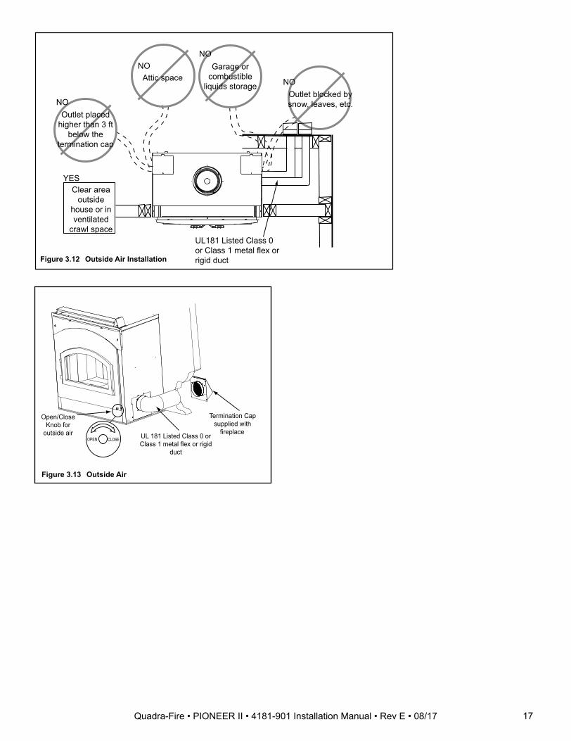
Outlet blocked bysnow, leaves, etc.
NO
Garage orcombustible
liquids storage
NO
Attic spaceNO
Outlet placedhigher than 3 ft
below thetermination cap
NO
UL181 Listed Class 0 or Class 1 metal flex orrigid duct
Clear area outside
house or in ventilated
crawl space
YES
Figure 3.12 Outside Air Installation
Figure 3.13 Outside Air
Termination Cap supplied with
fireplace UL 181 Listed Class 0 or Class 1 metal flex or rigid
duct
Open/Close Knob for
outside air CLOSE OPEN
17Quadra-Fire • PIONEER II • 4181-901 Installation Manual • Rev E • 08/17
DUCT RUN REQUIREMENTS
MAXIMUM Duct Run = 40-ft. (12 m) MINIMUM Duct Run = 36 in. (914 mm)
DUCTING MATERIAL
6 in. (152 mm) B-Vent OnlyDO NOT duct into existing furnace plenum
MINIMUM CLEARANCE TO COMBUSTIBLES
1 in. (25 mm) from the B-Vent1/2 in. (13 mm) from top & bottom of outlet box0 in. (0 mm) from the sides of outlet box12 in. (305 mm) from wall register to ceiling Refer to Figure 3.13.
CAUTION! ALL wiring should be done by a qualified elec-trician and shall be in compliance with local codes and with the National Electric Code NFPA/NEC No. 70-current. CSC22.1 Canadian Electric Code.
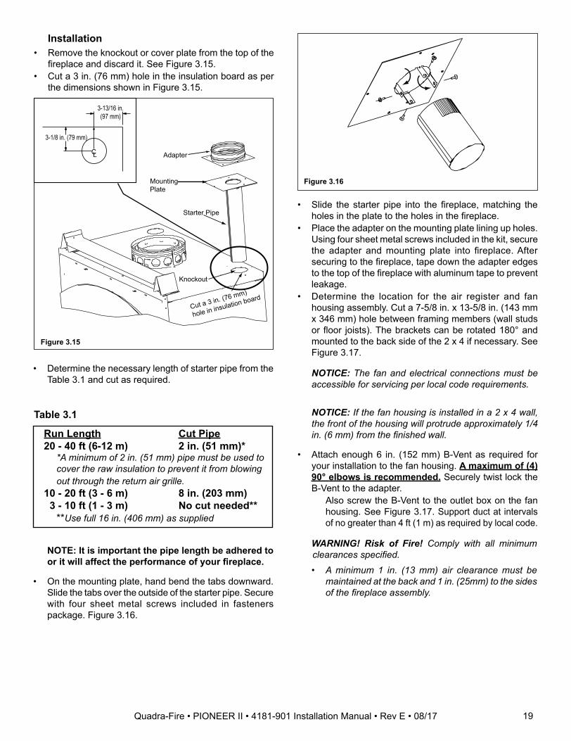
Possible Air Duct Runs / Locations
Figure 3.14 Minimum Clearances to Combustibles
I. Heat Zone Kit (Optional)The Heat-Zone accessory kit conveys warm air from the fireplace through air duct(s) to remote locations in the same room or other rooms of the building. You may install 1 or 2 Heat-Zone kits on the fireplace. Installation of this kit MUST be performed by a qualified service technician. If any parts are missing or damaged, contact your local dealer before starting installation. DO NOT install a dam-aged kit.
This kit is tested and safe when installed in accordance with this installation manual. It is your responsibility to read all instructions before starting installation and to fol-low these instructions carefully during installations.
The Heat-Zone® Wood kit is carefully engineered and must be installed only as specified. If you modify it or any of its components you will void the warranty and you may possibly cause a fire hazard. Installation must be done according to applicable local, state, provincial and/or national codes.
Plan the location of the fireplace and warm air duct run(s).
Ceiling RegisterWall Register
Floor Register
Two Duct Kits
Ceiling Register
12 in. (305mm) minimum clearance from register to ceiling
17 in. (432mm) minimum clearance to allow for venting
18 Quadra-Fire • PIONEER II • 4181-901 Installation Manual • Rev E • 08/17
Installation• Remove the knockout or cover plate from the top of the
fireplace and discard it. See Figure 3.15.• Cut a 3 in. (76 mm) hole in the insulation board as per
the dimensions shown in Figure 3.15.
Adapter
Mounting Plate
Starter Pipe
Knockout
Cut a 3 in. (76 mm)
hole in insulation board
3-13/16 in. (97 mm)
3-1/8 in. (79 mm)
CL
Run Length Cut Pipe20 - 40 ft (6-12 m) 2 in. (51 mm)*
*A minimum of 2 in. (51 mm) pipe must be used to cover the raw insulation to prevent it from blowing out through the return air grille.
10 - 20 ft (3 - 6 m) 8 in. (203 mm) 3 - 10 ft (1 - 3 m) No cut needed**
**Use full 16 in. (406 mm) as supplied
• Determine the necessary length of starter pipe from the Table 3.1 and cut as required.
Figure 3.15
• Slide the starter pipe into the fireplace, matching the holes in the plate to the holes in the fireplace.
• Place the adapter on the mounting plate lining up holes. Using four sheet metal screws included in the kit, secure the adapter and mounting plate into fireplace. After securing to the fireplace, tape down the adapter edges to the top of the fireplace with aluminum tape to prevent leakage.
• Determine the location for the air register and fan housing assembly. Cut a 7-5/8 in. x 13-5/8 in. (143 mm x 346 mm) hole between framing members (wall studs or floor joists). The brackets can be rotated 180° and mounted to the back side of the 2 x 4 if necessary. See Figure 3.17.
NOTICE: The fan and electrical connections must be accessible for servicing per local code requirements.
NOTICE: If the fan housing is installed in a 2 x 4 wall, the front of the housing will protrude approximately 1/4 in. (6 mm) from the finished wall.
• Attach enough 6 in. (152 mm) B-Vent as required for your installation to the fan housing. A maximum of (4) 90° elbows is recommended. Securely twist lock the B-Vent to the adapter. Also screw the B-Vent to the outlet box on the fan
housing. See Figure 3.17. Support duct at intervals of no greater than 4 ft (1 m) as required by local code.
Figure 3.16
WARNING! Risk of Fire! Comply with all minimum clearances specified.• A minimum 1 in. (13 mm) air clearance must be
maintained at the back and 1 in. (25mm) to the sides of the fireplace assembly.
NOTE: It is important the pipe length be adhered to or it will affect the performance of your fireplace.
• On the mounting plate, hand bend the tabs downward. Slide the tabs over the outside of the starter pipe. Secure with four sheet metal screws included in fasteners package. Figure 3.16.
Table 3.1
19Quadra-Fire • PIONEER II • 4181-901 Installation Manual • Rev E • 08/17
Securely Twist Lock B-Vent to Adapter
Secure B-Vent to Fan Housing with sheet metal screws
Return Air GrilleInstall with Louvers pointed down
Bracket
Can rotate 180o
2 x 4 Wall
Fan Housing
1/2 in. (13mm)clearance tocombustiblesmust bemaintained.
2 x 4 wall
Sheet Rock
Leave 1/4" (6mm) clearance from all 4 outer edges
Seal grille using gasketing supplied with the kit
• Install the variable speed wall rheostat (with setting on “OFF”) in a convenient location. This switch will control the Heat-Zone fan operation.
• Remove the junction box. Wire 110 VAC service TO the wall rheostat and FROM the wall rheostat to the fan junction box. Use wire nuts to secure the 110 VAC service wires to the hot (black) and neutral (white) fan wires and screw the 110 VAC ground wire to the junction box. See Figure 3.20.
• Secure the return air grille to the fan housing making sure it is flush. The grille must be installed with the louvers pointing down.
NOTICE: DO NOT USE ADJUSTABLE REGISTERS.
Junction Box Removed
Wire Clamp
Wire Nuts
Junction Box
Bla
ck
White
NOTICE: Secure the duct so that clearance to the fire-place outer wrap is maintained. Tape all seams with alumi-num tape 1-1/4 in. (32 mm) minimum width or as specified by local codes.)• Seal all the way around the inside of the return air grille to
prevent hot air being drawn back into the venting system using gasketing supplied with the kit. Leave 1/4 in. (6 mm) clearance from all four outer edges. Trim excess gasketing. See Figure 3.19.
Figure 3.17
Figure 3.18
Figure 3.19
Figure 3.20
20 Quadra-Fire • PIONEER II • 4181-901 Installation Manual • Rev E • 08/17
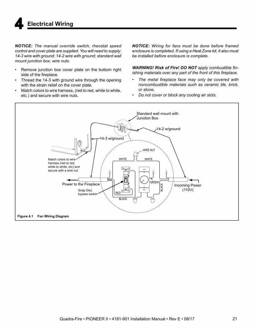
14-2 w/ground
Standard wall mount with Junction Box
14-3 w/ground
WIRE NUT
WHITE
GREEN
BLACK
BLAC
K
RED
WHITEMatch colors to wire harness (red to red, white to white, etc) and secure with a wire nut
Incoming Power(110V)
Power to the FireplaceSnap Disc bypass switch
Figure 4.1 Fan Wiring Diagram
NOTICE: The manual override switch, rheostat speed control and cover plate are supplied. You will need to supply: 14-3 wire with ground; 14-2 wire with ground; standard wall mount junction box; wire nuts.
• Remove junction box cover plate on the bottom right side of the fireplace.
• Thread the 14-3 with ground wire through the opening with the strain relief on the cover plate.
• Match colors to wire harness, (red to red, white to white, etc.) and secure with wire nuts.
WARNING! Risk of Fire! DO NOT apply combustible fin-ishing materials over any part of the front of this fireplace.• The metal fireplace face may only be covered with
noncombustible materials such as ceramic tile, brick, or stone.
• Do not cover or block any cooling air slots.
NOTICE: Wiring for fans must be done before framed enclosure is completed. If using a Heat Zone kit, it also must be installed before enclosure is complete.
4 Electrical Wiring
21Quadra-Fire • PIONEER II • 4181-901 Installation Manual • Rev E • 08/17
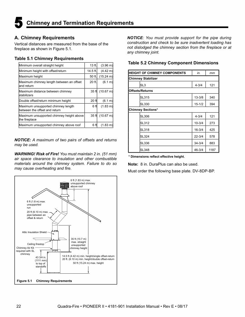
6 ft (1.8 m) max.unsupportedrun
20 ft (6.10 m) max.pipe between anoffset & return
Ceiling firestop
35 ft (10.7 m)max. straightunsupported
chimney height
14.5 ft (4.42 m) min. height/single offset-return20 ft. (6.10 m) min. height/double offset-return
50 ft (15.24 m) max. height
6 ft (1.83 m) max.unsupported chimneyabove roof
43 3/4 in.(1111 mm)to top of standoffs
Attic Insulation Shield
Chimney Air Kit required with SL
chimney
Figure 5.1 Chimney Requirements
NOTICE: A maximum of two pairs of offsets and returns may be used.
WARNING! Risk of Fire! You must maintain 2 in. (51 mm) air space clearance to insulation and other combustible materials around the chimney system. Failure to do so may cause overheating and fire.
NOTICE: You must provide support for the pipe during construction and check to be sure inadvertent loading has not dislodged the chimney section from the fireplace or at any chimney joint.
A. Chimney RequirementsVertical distances are measured from the base of the fireplace as shown in Figure 5.1.
5 Chimney and Termination Requirements
Table 5.2 Chimney Component DimensionsTable 5.1 Chimney Requirements
Minimum overall straight height 13 ft. (3.96 m)
Minimum height with offset/return 14.5 ft. (4.42 m)
Maximum height 50 ft. (15.24 m)
Maximum chimney length between an offset and return
20 ft. (6.1 m)
Maximum distance between chimney stabilizers
35 ft (10.67 m)
Double offset/return minimum height 20 ft (6.1 m)
Maximum unsupported chimney length between the offset and return
6 ft (1.83 m)
Maximum unsupported chimney height above the fireplace
35 ft (10.67 m)
Maximum unsupported chimney above roof 6 ft (1.83 m)
HEIGHT OF CHIMNEY COMPONENTS in. mm
Chimney Stabilizer
SL3 4-3/4 121
Offsets/Returns
SL315 13-3/8 340
SL330 15-1/2 394
Chimney Sections*
SL306 4-3/4 121
SL312 10-3/4 273
SL318 16-3/4 425
SL324 22-3/4 578
SL336 34-3/4 883
SL348 46-3/4 1187
* Dimensions reflect effective height.
Note: 8 in. DuraPlus can also be used.
Must order the following base plate. DV-8DP-BP.
22 Quadra-Fire • PIONEER II • 4181-901 Installation Manual • Rev E • 08/17
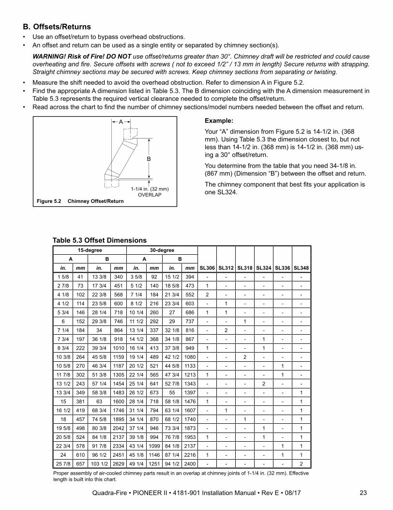
Table 5.3 Offset Dimensions15-degree 30-degree
SL306 SL312 SL318 SL324 SL336 SL348A B A B
in. mm in. mm in. mm in. mm1 5/8 41 13 3/8 340 3 5/8 92 15 1/2 394 - - - - - -
2 7/8 73 17 3/4 451 5 1/2 140 18 5/8 473 1 - - - - -
4 1/8 102 22 3/8 568 7 1/4 184 21 3/4 552 2 - - - - -
4 1/2 114 23 5/8 600 8 1/2 216 23 3/4 603 - 1 - - - -
5 3/4 146 28 1/4 718 10 1/4 260 27 686 1 1 - - - -
6 152 29 3/8 746 11 1/2 292 29 737 - - 1 - - -
7 1/4 184 34 864 13 1/4 337 32 1/8 816 - 2 - - - -
7 3/4 197 36 1/8 918 14 1/2 368 34 1/8 867 - - - 1 - -
8 3/4 222 39 3/4 1010 16 1/4 413 37 3/8 949 1 - - 1 - -
10 3/8 264 45 5/8 1159 19 1/4 489 42 1/2 1080 - - 2 - - -
10 5/8 270 46 3/4 1187 20 1/2 521 44 5/8 1133 - - - - 1 -
11 7/8 302 51 3/8 1305 22 1/4 565 47 3/4 1213 1 - - - 1 -
13 1/2 243 57 1/4 1454 25 1/4 641 52 7/8 1343 - - - 2 - -
13 3/4 349 58 3/8 1483 26 1/2 673 55 1397 - - - - - 1
15 381 63 1600 28 1/4 718 58 1/8 1476 1 - - - - 1
16 1/2 419 68 3/4 1746 31 1/4 794 63 1/4 1607 - 1 - - - 1
18 457 74 5/8 1895 34 1/4 870 68 1/2 1740 - - 1 - - 1
19 5/8 498 80 3/8 2042 37 1/4 946 73 3/4 1873 - - - 1 - 1
20 5/8 524 84 1/8 2137 39 1/8 994 76 7/8 1953 1 - - 1 - 1
22 3/4 578 91 7/8 2334 43 1/4 1099 84 1/8 2137 - - - - 1 1
24 610 96 1/2 2451 45 1/8 1146 87 1/4 2216 1 - - - 1 1
25 7/8 657 103 1/2 2629 49 1/4 1251 94 1/2 2400 - - - - - 2
Proper assembly of air-cooled chimney parts result in an overlap at chimney joints of 1-1/4 in. (32 mm). Effective length is built into this chart.
B. Offsets/Returns• Use an offset/return to bypass overhead obstructions.• An offset and return can be used as a single entity or separated by chimney section(s).
WARNING! Risk of Fire! DO NOT use offset/returns greater than 30°. Chimney draft will be restricted and could cause overheating and fire. Secure offsets with screws ( not to exceed 1/2” / 13 mm in length) Secure returns with strapping. Straight chimney sections may be secured with screws. Keep chimney sections from separating or twisting.
• Measure the shift needed to avoid the overhead obstruction. Refer to dimension A in Figure 5.2.• Find the appropriate A dimension listed in Table 5.3. The B dimension coinciding with the A dimension measurement in
Table 5.3 represents the required vertical clearance needed to complete the offset/return.• Read across the chart to find the number of chimney sections/model numbers needed between the offset and return.
A
B
1-1/4 in. (32 mm)OVERLAP
Figure 5.2 Chimney Offset/Return
Example: Your “A” dimension from Figure 5.2 is 14-1/2 in. (368 mm). Using Table 5.3 the dimension closest to, but not less than 14-1/2 in. (368 mm) is 14-1/2 in. (368 mm) us-ing a 30° offset/return.
You determine from the table that you need 34-1/8 in. (867 mm) (Dimension “B”) between the offset and return.
The chimney component that best fits your application is one SL324.
23Quadra-Fire • PIONEER II • 4181-901 Installation Manual • Rev E • 08/17
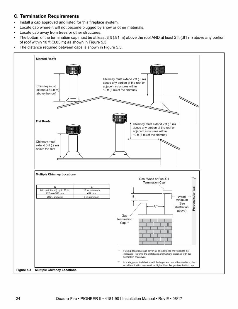
Slanted Roofs
Flat Roofs
Chimney mustextend 3 ft (.9 m)above the roof
Chimney must extend 2 ft (.6 m)above any portion of the roof oradjacent structures within 10 ft (3 m) of the chimney
Chimney mustextend 3 ft (.9 m)above the roof
Chimney must extend 2 ft (.6 m)above any portion of the roof oradjacent structures within10 ft (3 m) of the chimney
Multiple Chimney Locations
A B6 in. (minimum) up to 20 in.
152 mm/508 mm18 in. minimum
457 mm20 in. and over 0 in. minimum
Gas, Wood or Fuel OilTermination Cap
WoodMinimum
(Seeillustration
above)
B
GasTermination
Cap **
A *
Per
pend
icul
ar W
all
* If using decorative cap cover(s), this distance may need to be increased. Refer to the installation instructions supplied with the decorative cap cover.
** In a staggered installation with both gas and wood terminations, the wood termination cap must be higher than the gas termination cap.
Figure 5.3 Multiple Chimney Locations
C. Termination Requirements• Install a cap approved and listed for this fireplace system.• Locate cap where it will not become plugged by snow or other materials.• Locate cap away from trees or other structures.• The bottom of the termination cap must be at least 3 ft (.91 m) above the roof AND at least 2 ft (.61 m) above any portion
of roof within 10 ft (3.05 m) as shown in Figure 5.3. • The distance required between caps is shown in Figure 5.3.
24 Quadra-Fire • PIONEER II • 4181-901 Installation Manual • Rev E • 08/17
6 Chimney Installation
Termination Cap
Additionalsupport fortall chimneys
Storm Collar
Maintain minimumclearances to combustibles asspecified
Chimney must extendbeyond combustibleroof structure
Maintain minimumheight of chimneyabove roof
Install roof flashingaccording to minimumrequirements
Offsets/returnsmay not exceed30° from vertical Support straps for offsets/
returns must be securedto adequate framing
Ceiling firestopsare required wherechimney passes through ceiling orfloor
Attic Shield isrequired where chimneypasses through attic
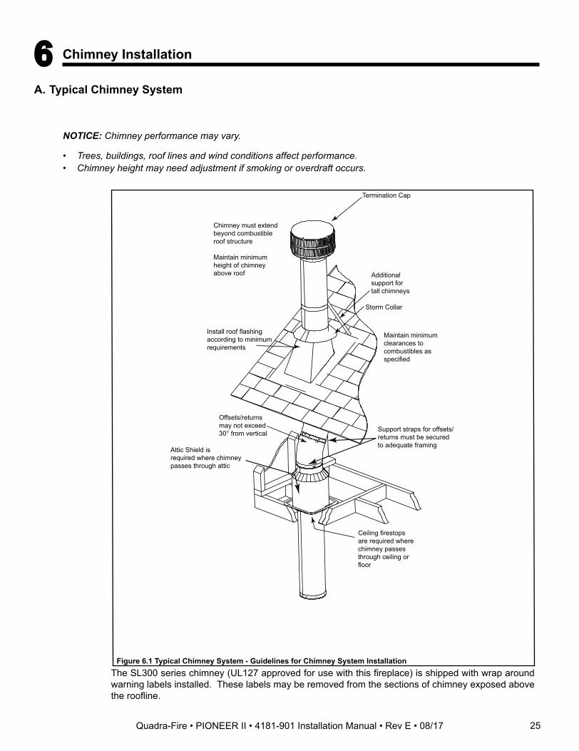
Figure 6.1 Typical Chimney System - Guidelines for Chimney System Installation
NOTICE: Chimney performance may vary.
• Trees, buildings, roof lines and wind conditions affect performance.• Chimney height may need adjustment if smoking or overdraft occurs.
A. Typical Chimney System
25
The SL300 series chimney (UL127 approved for use with this fireplace) is shipped with wrap around warning labels installed. These labels may be removed from the sections of chimney exposed above the roofline.
Quadra-Fire • PIONEER II • 4181-901 Installation Manual • Rev E • 08/17
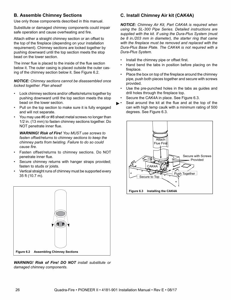
Attach Flue First
CAK4A
Secure with Screws Provided
Push TogetherSecure to Top
C. Install Chimney Air kit (CAK4A)
NOTICE: Chimney Air Kit, Part CAK4A is required when using the SL-300 Pipe Series. Detailed instructions are supplied with the kit. If using the Dura-Plus System (must be 8 in./203 mm in diameter), the starter ring that came with the fireplace must be removed and replaced with the Dura-Plus Base Plate. The CAK4A is not required with a Dura-Plus System.
• Install the chimney pipe or offset first.• Hand bend the tabs in position before placing on the
fireplace.• Place the box on top of the fireplace around the chimney
pipe, push both pieces together and secure with screws provided.
• Use the pre-punched holes in the tabs as guides and drill holes through the fireplace top.
• Secure the CAK4A in place. See Figure 6.3.• Seal around the kit at the flue and at the top of the
can with high temp caulk with a minimum rating of 500 degrees. See Figure 6.3.
Figure 6.3 Installing the CAK4A
NOTICE: Chimney sections cannot be disassembled once locked together. Plan ahead!
• Lock chimney sections and/or offsets/returns together by pushing downward until the top section meets the stop bead on the lower section.
• Pull on the top section to make sure it is fully engaged and will not separate.
• You may use #6 or #8 sheet metal screws no longer than 1/2 in. (13 mm) to fasten chimney sections together. Do NOT penetrate inner flue.
WARNING! Risk of Fire! You MUST use screws to fasten offset/returns to chimney sections to keep the chimney parts from twisting. Failure to do so could cause fire.
• Fasten offset/returns to chimney sections. Do NOT penetrate inner flue.
• Secure chimney returns with hanger straps provided; fasten to studs or joists.
• Vertical straight runs of chimney must be supported every 35 ft (10.7 m).
B. Assemble Chimney Sections Use only those components described in this manual.
Substitute or damaged chimney components could impair safe operation and cause overheating and fire.
Attach either a straight chimney section or an offset to the top of the fireplace (depending on your installation requirement). Chimney sections are locked together by pushing downward until the top section meets the stop bead on the lower section.
The inner flue is placed to the inside of the flue section below it. The outer casing is placed outside the outer cas-ing of the chimney section below it. See Figure 6.2.
WARNING! Risk of Fire! DO NOT install substitute or damaged chimney components.
Figure 6.2 Assembling Chimney Sections
26 Quadra-Fire • PIONEER II • 4181-901 Installation Manual • Rev E • 08/17
►
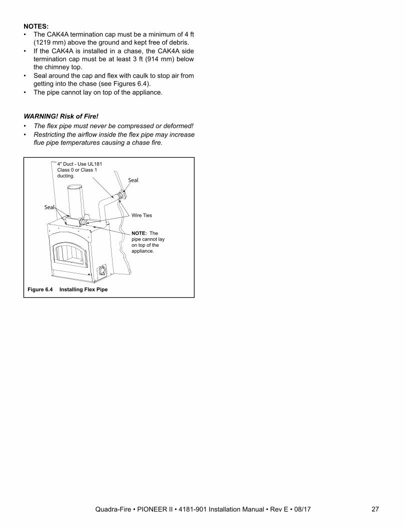
NOTES: • The CAK4A termination cap must be a minimum of 4 ft
(1219 mm) above the ground and kept free of debris. • If the CAK4A is installed in a chase, the CAK4A side
termination cap must be at least 3 ft (914 mm) below the chimney top.
• Seal around the cap and flex with caulk to stop air from getting into the chase (see Figures 6.4).
• The pipe cannot lay on top of the appliance.
Figure 6.4 Installing Flex Pipe
WARNING! Risk of Fire!• The flex pipe must never be compressed or deformed!• Restricting the airflow inside the flex pipe may increase
flue pipe temperatures causing a chase fire.
Wire TiesSeal
Seal
4" Duct - Use UL181 Class 0 or Class 1 ducting.
NOTE: The pipe cannot lay on top of the appliance.
27Quadra-Fire • PIONEER II • 4181-901 Installation Manual • Rev E • 08/17
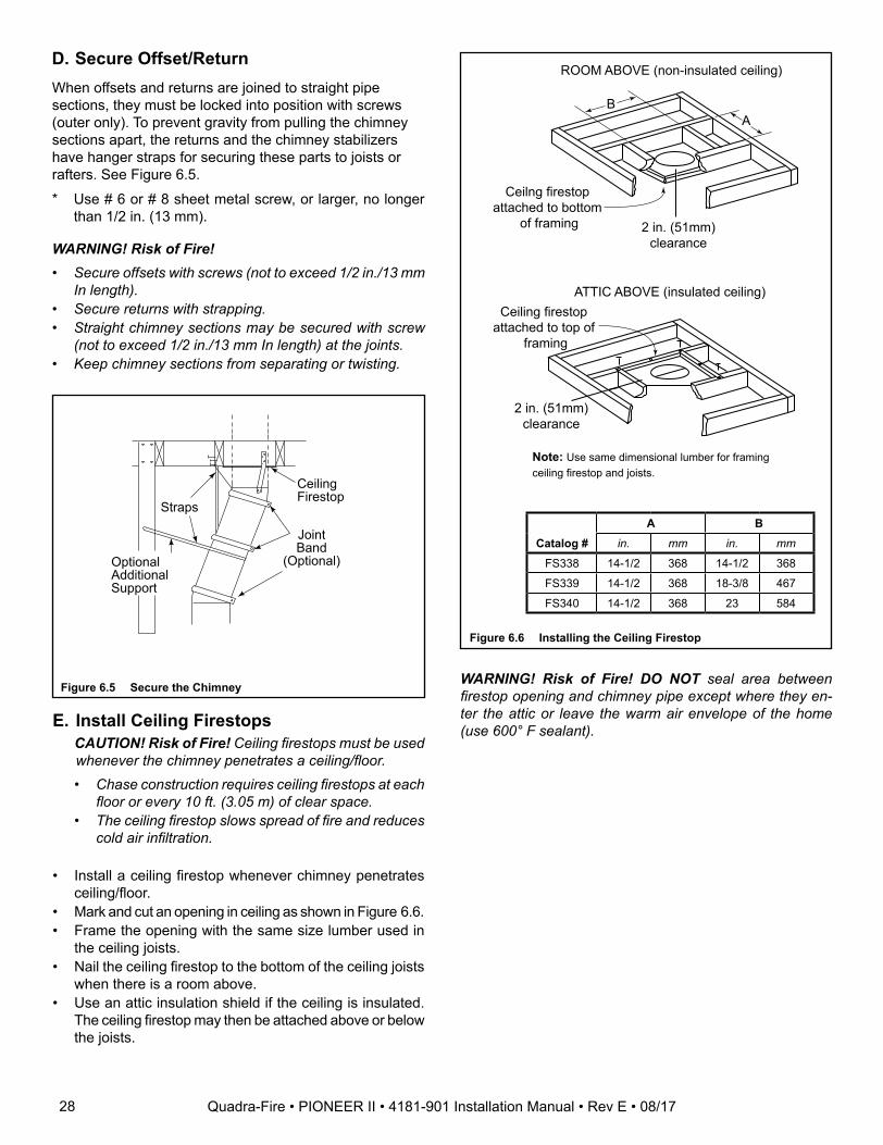
D. Secure Offset/Return
E. Install Ceiling Firestops CAUTION! Risk of Fire! Ceiling firestops must be used
whenever the chimney penetrates a ceiling/floor.• Chase construction requires ceiling firestops at each
floor or every 10 ft. (3.05 m) of clear space.• The ceiling firestop slows spread of fire and reduces
cold air infiltration.
• Install a ceiling firestop whenever chimney penetrates ceiling/floor.
• Mark and cut an opening in ceiling as shown in Figure 6.6.• Frame the opening with the same size lumber used in
the ceiling joists.• Nail the ceiling firestop to the bottom of the ceiling joists
when there is a room above.• Use an attic insulation shield if the ceiling is insulated.
The ceiling firestop may then be attached above or below the joists.
ROOM ABOVE (non-insulated ceiling)
ATTIC ABOVE (insulated ceiling)
B A
Ceilng firestop attached to bottom
of framing
Ceiling firestop attached to top of
framing
Note: Use same dimensional lumber for framing ceiling firestop and joists.
2 in. (51mm) clearance
2 in. (51mm) clearance
Catalog #A B
in. mm in. mm
FS338 14-1/2 368 14-1/2 368
FS339 14-1/2 368 18-3/8 467
FS340 14-1/2 368 23 584
WARNING! Risk of Fire! DO NOT seal area between firestop opening and chimney pipe except where they en-ter the attic or leave the warm air envelope of the home (use 600° F sealant).
Figure 6.6 Installing the Ceiling Firestop
When offsets and returns are joined to straight pipe sections, they must be locked into position with screws (outer only). To prevent gravity from pulling the chimney sections apart, the returns and the chimney stabilizers have hanger straps for securing these parts to joists or rafters. See Figure 6.5.
* Use # 6 or # 8 sheet metal screw, or larger, no longer than 1/2 in. (13 mm).
WARNING! Risk of Fire!• Secure offsets with screws (not to exceed 1/2 in./13 mm
In length).• Secure returns with strapping.• Straight chimney sections may be secured with screw
(not to exceed 1/2 in./13 mm In length) at the joints.• Keep chimney sections from separating or twisting.
CeilingFirestop
Straps
OptionalAdditionalSupport
JointBand
(Optional)
Figure 6.5 Secure the Chimney
28 Quadra-Fire • PIONEER II • 4181-901 Installation Manual • Rev E • 08/17

Installation of a ceiling firestop is required:
• Refer to Figures 5.5, 5.6, 5.7.• If the attic shield is pre-rolled continue. If it is a flat part,
try and roll it up to aid in wrapping it around the chimney.• Pre-bend all the tabs in at the top to 45°.• Wrap the shield (around the chimney if already installed)
until you have an overlap and the three holes on each side match up (large holes on top).
• Insert three screws into the matching holes to form a tube starting at the bottom.
• Bend the tabs on the bottom of the tube inward to 90° to maintain chimney air space.
• Rest the insulation shield on the ceiling firestop below.• Tape off any opening around the bottom.
If you wish to make a custom shield or barrier, follow these guidelines:
• Metal is preferred, although any material stiff enough to hold back the insulation can be used.
WARNING! Risk of Fire! Use of cardboard or other materials that can deflect under humidity or other envi-ronmental conditions is not recommended.
• The shield or barrier must be tall enough to extend above the insulation and prevent blown-in insulation from spilling into the cavity.
• Maintain specified air spaces around chimney.• Check instructions and local codes for further details.
Insert three screws
Pre-bend the tabs to rest against pipe to prevent insulation from falling in.
(5)Tabs bent in 90°
Figure 5.5 Prepare Attic Insulation Shield
F. Install Attic Insulation ShieldWARNING! Risk of Fire! You MUST install an attic insu-lation shield when there is any possibility of insulation or other combustible material coming into contact with the chimney. • DO NOT pack insulation between the chimney and the
attic insulation shield. • Failure to keep insulation and other materials away from
chimney pipe could cause fire.• DO NOT offset chimney inside insulation shield.• Combustible material may come in contact with the attic
insulation shield as long as the required clearances are maintained to the chimney pipe.
Double-check the Chimney AssemblyContinue assembling the chimney sections up through the ceiling firestops as needed. While doing so, be aware of the height and unsupported chimney length limitations given under Section 5.
Check each section by pulling up slightly from the top to ensure proper engagement before installing the suc-ceeding sections. If they have been connected correct-ly, they will not disengage when tested.
Figure 5.6 Install Attic Insulation Shield (firestop above ceiling)
5 Tabs bentin 90°
Tabs bent in to rest against pipe
Attic Insulation Shield
Ceiling Firestop
10-1/2 in.(267 mm)
14-1/2 in. (368 mm)diameter
InsulationInsulation
Pipe
Pipe
2 in. (51 mm)air space
Seal with tape
5 Tabs bentin 90°
Tabs bent in to rest against pipe
Attic Insulation Shield
Ceiling Firestop10-1/2 in.(267 mm)
14-1/2 in. (368 mm)diameter
InsulationInsulation
Pipe
Pipe
2 in. (51 mm)air space
Seal with tape
Figure 5.7 Install Attic Insulation Shield (firestop below ceiling)
29Quadra-Fire • PIONEER II • 4181-901 Installation Manual • Rev E • 08/17
►
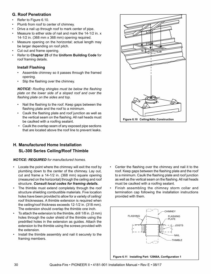
G. Roof Penetration• Refer to Figure 6.10.• Plumb from roof to center of chimney.• Drive a nail up through roof to mark center of pipe.• Measure to either side of nail and mark the 14-1/2 in. x
14-1/2 in. (368 mm x 368 mm) opening required.• Measure opening on the horizontal; actual length may
be larger depending on roof pitch.• Cut out and frame opening.• Refer to Chapter 25 of the Uniform Building Code for
roof framing details.
Figure 6.10 Ceiling/Attic Construction
Install Flashing• Assemble chimney so it passes through the framed
opening.• Slip the flashing over the chimney.
NOTICE: Roofing shingles must be below the flashing plate on the lower side of a sloped roof and over the flashing plate on the sides and top.
• Nail the flashing to the roof. Keep gaps between the flashing plate and the roof to a minimum.
• Caulk the flashing plate and roof junction as well as the vertical seam on the flashing. All nail heads must be caulked with a roofing sealant.
• Caulk the overlap seam of any exposed pipe sections that are located above the roof line to prevent leaks.
CHIMNEY
FLASHING PLATE
JOISTS
NAIL
THIMBLE
FLASHING
Figure 6.11 Installing Part: 12966A, Configuration 1
NOTICE: REQUIRED for manufactured homes.
• Locate the point where the chimney will exit the roof by plumbing down to the center of the chimney. Lay out, cut and frame a 14-1/2 in. (368 mm) square opening (measured on the horizontal) through the ceiling and roof structure. Consult local codes for framing details.
• The thimble must extend completely through the roof structure shielding combustible materials. Five location holes have been provided to allow for a variety of ceiling/roof thicknesses. A thimble extension is required when the ceiling/roof thickness exceeds 12-1/2 in. (318 mm). The extension should overlap the thimble one inch.
• To attach the extension to the thimble, drill 1/8 in. (3 mm) holes through the outer shield of the thimble using the predrilled holes in the extension as guides. Attach the extension to the thimble using the screws provided with the extension.
• Install the thimble assembly and nail it securely to the framing members.
H. Manufactured Home Installation SL-300 Series Ceiling/Roof Thimble
• Center the flashing over the chimney and nail it to the roof. Keep gaps between the flashing plate and the roof to a minimum. Caulk the flashing plate and roof junction as well as the vertical seam on the flashing. All nail heads must be caulked with a roofing sealant.
• Finish assembling the chimney storm collar and termination cap following the installation instructions provided with them.
30 Quadra-Fire • PIONEER II • 4181-901 Installation Manual • Rev E • 08/17
NAIL
FLASHING PLATE
CHIMNEY
THIMBLE EXTENSION
SCREW
FLASHING
THIMBLE ADJUSTABLE EXTENSION HOLES
Figure 6.13 Installing Part 12966A Configuration 3
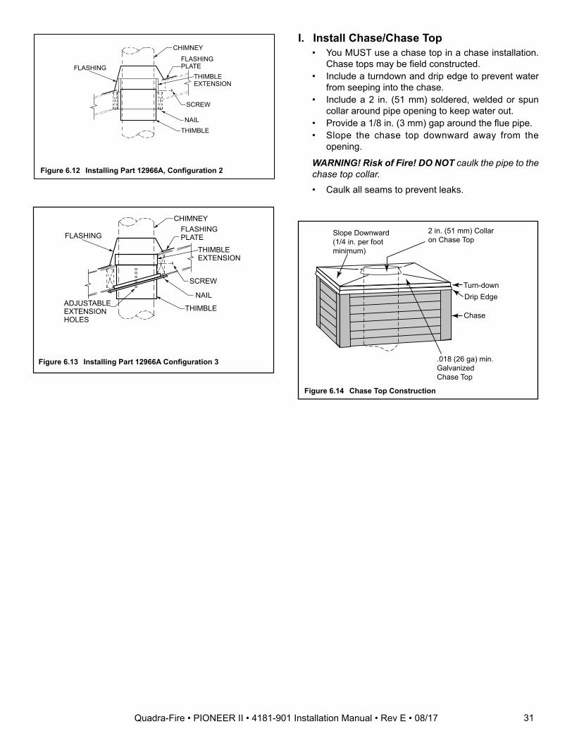
I. Install Chase/Chase Top• You MUST use a chase top in a chase installation.
Chase tops may be field constructed.• Include a turndown and drip edge to prevent water
from seeping into the chase.• Include a 2 in. (51 mm) soldered, welded or spun
collar around pipe opening to keep water out.• Provide a 1/8 in. (3 mm) gap around the flue pipe.• Slope the chase top downward away from the
opening.
WARNING! Risk of Fire! DO NOT caulk the pipe to the chase top collar. • Caulk all seams to prevent leaks.
Slope Downward(1/4 in. per footminimum)
Turn-down Drip Edge
Chase
2 in. (51 mm) Collar on Chase Top
.018 (26 ga) min. Galvanized Chase Top
Figure 6.14 Chase Top Construction
FLASHING
CHIMNEY
FLASHING PLATE
NAIL THIMBLE
SCREW
THIMBLE EXTENSION
Figure 6.12 Installing Part 12966A, Configuration 2
31Quadra-Fire • PIONEER II • 4181-901 Installation Manual • Rev E • 08/17
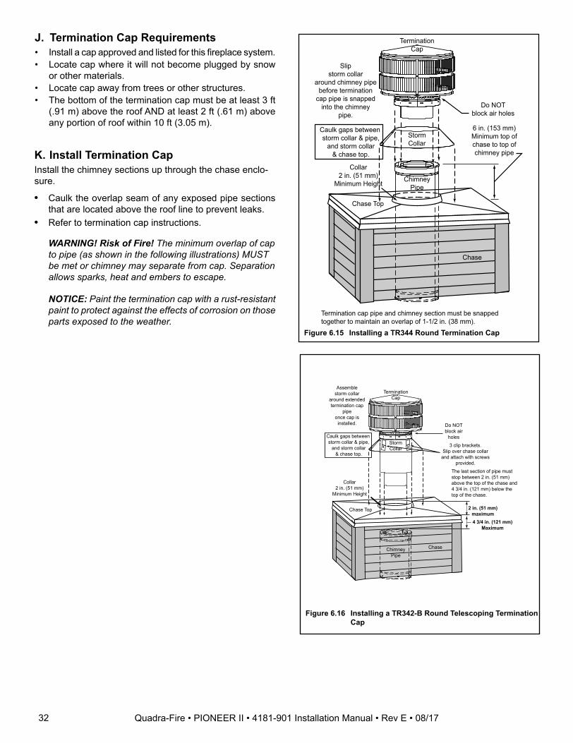
J. Termination Cap Requirements• Install a cap approved and listed for this fireplace system.• Locate cap where it will not become plugged by snow
or other materials.• Locate cap away from trees or other structures.• The bottom of the termination cap must be at least 3 ft
(.91 m) above the roof AND at least 2 ft (.61 m) above any portion of roof within 10 ft (3.05 m).
StormCollar
ChimneyPipe
Chase Top
TerminationCap
Chase
6 in. (153 mm)Minimum top ofchase to top ofchimney pipe
Collar2 in. (51 mm)
Minimum Height
Do NOTblock air holes
Caulk gaps between storm collar & pipe,
and storm collar& chase top.
Termination cap pipe and chimney section must be snapped together to maintain an overlap of 1-1/2 in. (38 mm).
Slipstorm collar
around chimney pipebefore termination
cap pipe is snapped into the chimney
pipe.
Figure 6.15 Installing a TR344 Round Termination Cap
K. Install Termination CapInstall the chimney sections up through the chase enclo-sure.
• Caulk the overlap seam of any exposed pipe sections that are located above the roof line to prevent leaks.
• Refer to termination cap instructions.
WARNING! Risk of Fire! The minimum overlap of cap to pipe (as shown in the following illustrations) MUST be met or chimney may separate from cap. Separation allows sparks, heat and embers to escape.
NOTICE: Paint the termination cap with a rust-resistant paint to protect against the effects of corrosion on those parts exposed to the weather.
Figure 6.16 Installing a TR342-B Round Telescoping Termination Cap
StormCollar
ChimneyPipe
Chase Top
TerminationCap
Chase
4 3/4 in. (121 mm)Maximum
Collar2 in. (51 mm)
Minimum Height
Caulk gaps between storm collar & pipe,
and storm collar& chase top.
Do NOT block air
holes3 clip brackets.
Slip over chase collarand attach with screws
provided.
Assemblestorm collar
around extended termination cap
pipeonce cap is
installed.
The last section of pipe must stop between 2 in. (51 mm) above the top of the chase and 4 3/4 in. (121 mm) below the top of the chase.
2 in. (51 mm)maximum
32 Quadra-Fire • PIONEER II • 4181-901 Installation Manual • Rev E • 08/17
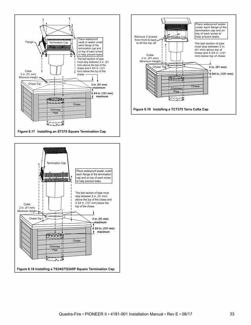
Figure 6.19 Installing a TCT375 Terra Cotta Cap
Figure 6.17 Installing an ST375 Square Termination Cap
ChimneyPipe
Chase Top
Termination Cap
Chase
Collar2 in. (51 mm)
Minimum Height
Place waterproof caulk or sealer under each flange of the termination cap and on top of each screw to help prevent leaks.
Flange
2 in. (51 mm)maximum
4 3/4 in. (121 mm)maximum
The last section of pipe must stop between 2 in. (51 mm) above the top of the chase and 4 3/4 in. (121 mm) below the top of the chase.
ChimneyPipe
Chase Top
Termination Cap
Chase
Collar2 in. (51 mm)
Minimum Height
Place waterproof sealer under each flange of the termination cap and on top of each screw to help prevent leaks.
2 in. (51 mm)maximum
4 3/4 in. (121 mm)maximum
The last section of pipe must stop between 2 in. (51 mm) above the top of the chase and 4 3/4 in. (121 mm) below the top of the chase.
Figure 6.18 Installing a TS345/TS345P Square Termination Cap
ChimneyPipe
Chase Top
Termination Cap
Chase
Collar2 in. (51 mm)
Minimum Height
Remove 2 screws from front & back to lift the top off
Place waterproof sealer under each flange of the termination cap and on top of each screw to help prevent leaks.
The last section of pipe must stop between 2 in. (51 mm) above top of chase and 4-3/4 in. (121 mm) below top of chase
2 in. (51 mm)
4-3/4 in. (121 mm)
33Quadra-Fire • PIONEER II • 4181-901 Installation Manual • Rev E • 08/17
7 Finishing
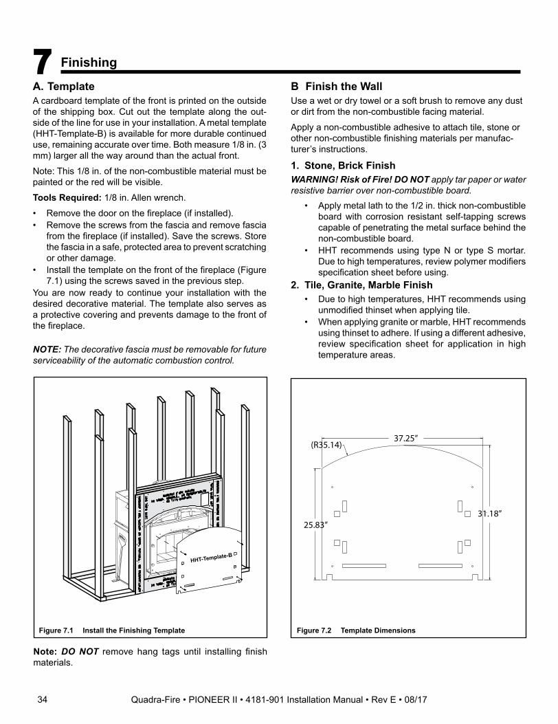
A. TemplateA cardboard template of the front is printed on the outside of the shipping box. Cut out the template along the out-side of the line for use in your installation. A metal template (HHT-Template-B) is available for more durable continued use, remaining accurate over time. Both measure 1/8 in. (3 mm) larger all the way around than the actual front.
Note: This 1/8 in. of the non-combustible material must be painted or the red will be visible.
Tools Required: 1/8 in. Allen wrench.
• Remove the door on the fireplace (if installed).• Remove the screws from the fascia and remove fascia
from the fireplace (if installed). Save the screws. Store the fascia in a safe, protected area to prevent scratching or other damage.
• Install the template on the front of the fireplace (Figure 7.1) using the screws saved in the previous step.
You are now ready to continue your installation with the desired decorative material. The template also serves as a protective covering and prevents damage to the front of the fireplace.
NOTE: The decorative fascia must be removable for future serviceability of the automatic combustion control.
Figure 7.1 Install the Finishing Template
Note: DO NOT remove hang tags until installing finish materials.
B Finish the WallUse a wet or dry towel or a soft brush to remove any dust or dirt from the non-combustible facing material.
Apply a non-combustible adhesive to attach tile, stone or other non-combustible finishing materials per manufac-turer’s instructions.
1. Stone, Brick FinishWARNING! Risk of Fire! DO NOT apply tar paper or water resistive barrier over non-combustible board.
• Apply metal lath to the 1/2 in. thick non-combustible board with corrosion resistant self-tapping screws capable of penetrating the metal surface behind the non-combustible board.
• HHT recommends using type N or type S mortar. Due to high temperatures, review polymer modifiers specification sheet before using.
2. Tile, Granite, Marble Finish• Due to high temperatures, HHT recommends using
unmodified thinset when applying tile.• When applying granite or marble, HHT recommends
using thinset to adhere. If using a different adhesive, review specification sheet for application in high temperature areas.
HHT-Template-B
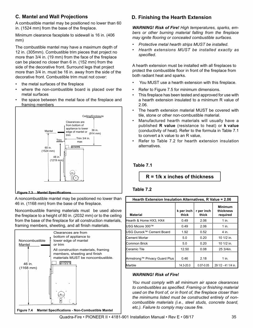
Figure 7.2 Template Dimensions
37.25”
25.83”
(R35.14)
31.18”
34 Quadra-Fire • PIONEER II • 4181-901 Installation Manual • Rev E • 08/17
60 in.(1524 mm)
Mantel
Clearances are from bottom of appliance to lower edge of mantel or trim
Trim
48 in.(1219 mm)
Trim 3/4 in. max
36 in.(914 mm)
Ceiling/Enclosure
Figure 7.3 Mantel Specifications
D. Finishing the Hearth Extension
Table 7.1
R = 1/k x inches of thickness
Table 7.2
WARNING! Risk of Fire! High temperatures, sparks, em-bers or other burning material falling from the fireplace may ignite flooring or concealed combustible surfaces.• Protective metal hearth strips MUST be installed.• Hearth extensions MUST be installed exactly as
specified.
A hearth extension must be installed with all fireplaces to protect the combustible floor in front of the fireplace from both radiant heat and sparks.
• You MUST use a hearth extension with this fireplace.
• Refer to Figure 7.5 for minimum dimensions.• This fireplace has been tested and approved for use with
a hearth extension insulated to a minimum R value of 2.06.
• The hearth extension material MUST be covered with tile, stone or other non-combustible material.
• Manufactured hearth materials will usually have a published R value (resistance to heat) or k value (conductivity of heat). Refer to the formula in Table 7.1 to convert a k value to an R value,
• Refer to Table 7.2 for hearth extension insulation alternatives.
Hearth Extension Insulation Alternatives, R Value = 2.06
Materialk per inch
thickr per inch
thick
Minimum thickness required
Hearth & Home HX3, HX4 0.49 2.06 1 in.
USG Micore 300™ 0.49 2.06 1 in.
USG Durock™ Cement Board 1.92 0.52 4 in.
Cement Mortar 5.0 0.20 10 1/2 in.
Common Brick 5.0 0.20 10 1/2 in.
Ceramic Tile 12.50 0.08 25 3/4in.
Armstrong™ Privacy Guard Plus 0.46 2.18 1 in.
Marble 14.3-20.0 0.07-0.05 29 1/2 - 41 1/4 in.
WARNING! Risk of Fire!
You must comply with all minimum air space clearances to combustibles as specified. Framing or finishing material used on the front of, or in front of, the fireplace closer than the minimums listed must be constructed entirely of non-combustible materials (i.e., steel studs, concrete board, etc.). Failure to comply may cause fire.
C. Mantel and Wall ProjectionsA combustible mantel may be positioned no lower than 60 in. (1524 mm) from the base of the fireplace.
Minimum clearance faceplate to sidewall is 16 in. (406 mm)
The combustible mantel may have a maximum depth of 12 in. (305mm). Combustible trim pieces that project no more than 3/4 in. (19 mm) from the face of the fireplace can be placed no closer than 6 in. (152 mm) from the side of the decorative front. Surround legs that project more than 3/4 in. must be 16 in. away from the side of the decorative front. Combustible trim must not cover:
• the metal surfaces of the fireplace• where the non-combustible board is placed over the
metal surfaces• the space between the metal face of the fireplace and
framing members
35
A noncombustible mantel may be positioned no lower than 46 in. (1168 mm) from the base of the fireplace.
Noncombustible framing materials must be used above the fireplace to a height of 80 in. (2032 mm) or to the ceiling from the base of the fireplace for all construction materials, framing members, sheeting, and all finish materials.
46 in.(1168 mm)
Noncombustible Mantel
Clearances are from bottom of appliance to lower edge of mantel or trimAll construction materials, framing members, sheeting and finish materials MUST be noncombustible.
Figure 7.4 Mantel Specifications - Non-Combustible Mantel
Quadra-Fire • PIONEER II • 4181-901 Installation Manual • Rev E • 08/17
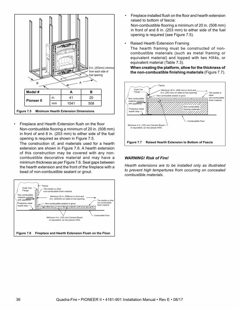
8 in. (203mm) minimum from each side offuel opening
AB
Figure 7.5 Minimum Hearth Extension Dimensions
Model # A B
Pioneer IIin. 41 20mm 1041 508
• Fireplace and Hearth Extension flush on the floor Non-combustible flooring a minimum of 20 in. (508 mm)
in front of and 8 in. (203 mm) to either side of the fuel opening is required as shown in Figure 7.5.
The construction of, and materials used for a hearth extension are shown in Figure 7.6. A hearth extension of this construction may be covered with any non-combustible decorative material and may have a minimum thickness as per Figure 7.6. Seal gaps between the hearth extension and the front of the fireplace with a bead of non-combustible sealant or grout.
FasciaOuter Can Flange
Protective metalhearth strip
Tile,marble or other non-combustible finish material
Minimum 4 in. (102 mm) Cement Board or equivalent, (or two pieces HX4)
Minimum 20 in. (508mm) in front and 8 in. (203mm) on sides to fuel opening
Combustible Floor
. . . . . . . . . . . . . . . . . . . . . . . . . . . . . . . . . . . . . . .. . . . . . . . . . . . . . . . . . . . . . . . . . . . . . . . . . . . . . .. . .
. . .
. . .
. .
Non-combustible material supplied with appliance.
. . .
. . .
. . .
. .
Non-combustible sealant or groutTile,marble or other non-combustible finish material
Figure 7.6 Fireplace and Hearth Extension Flush on the Floor.
• Raised Hearth Extension Framing The hearth framing must be constructed of non-
combustible materials (such as metal framing or equivalent material) and topped with two HX4s, or equivalent material (Table 7.3).
When creating the platform, allow for the thickness of the non-combustible finishing materials (Figure 7.7).
Outer Can Flange
Non-combustible material supplied with appliance
Fascia
Protective metalhearth strip
Minimum 4 in. (102 mm) Cement Board or equivalent, (or two pieces HX4)
Minimum 20 in. (508 mm) in front and 8 in. (203 mm) on sides to fuel opening
Combustible Floor
Non-combustible sealant or groutTile,marble or other non-combustible finish material. . . . . . . . . . . . . . . . . . . . . . . . . . . . . . . . . . . . . . .. . . . . . . . . . . . . . . . . . . . . . . . . . . . . . . . . . . . . . .
. . .
. . .
. . .
. .
. . .
. . .
. . .
. .
Non-combustibleframing materials
Figure 7.7 Raised Hearth Extension to Bottom of Fascia
• Fireplace installed flush on the floor and hearth extension raised to bottom of fascia:
Non-combustible flooring a minimum of 20 in. (508 mm) in front of and 8 in. (203 mm) to either side of the fuel opening is required (see Figure 7.5).
WARNING! Risk of Fire!
Hearth extensions are to be installed only as illustrated to prevent high tempertures from occurring on concealed combustible materials.
36 Quadra-Fire • PIONEER II • 4181-901 Installation Manual • Rev E • 08/17
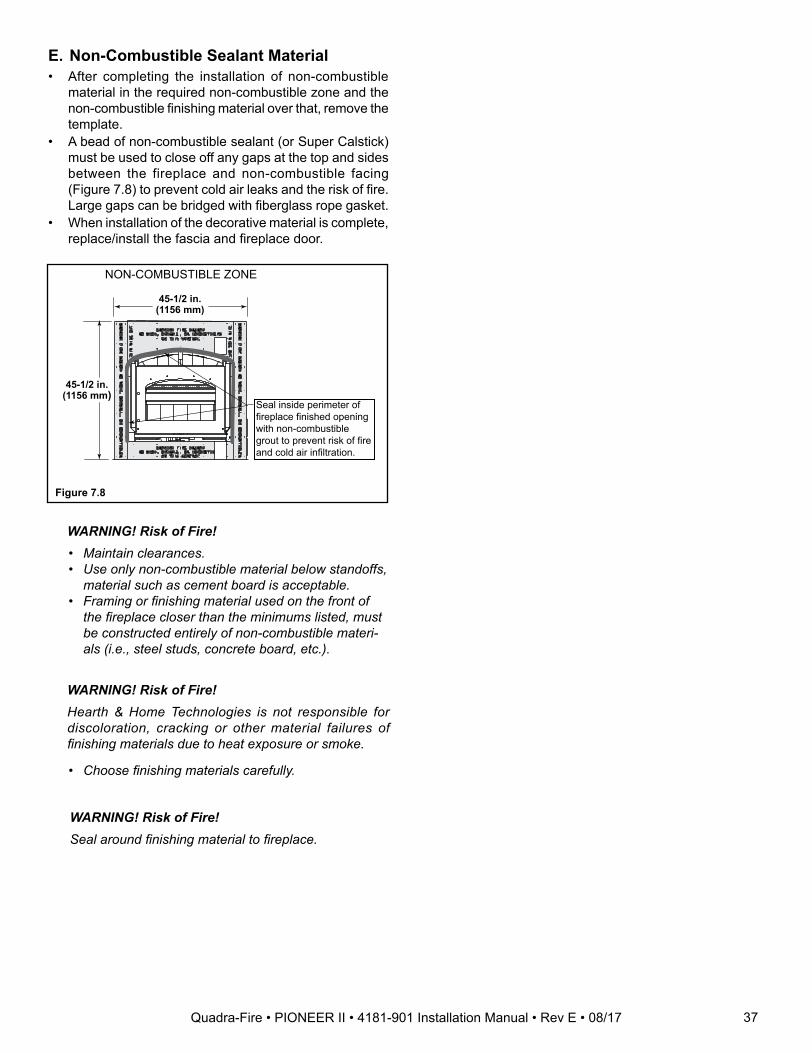
WARNING! Risk of Fire! • Maintain clearances. • Use only non-combustible material below standoffs,
material such as cement board is acceptable. • Framing or finishing material used on the front of
the fireplace closer than the minimums listed, must be constructed entirely of non-combustible materi-als (i.e., steel studs, concrete board, etc.).
WARNING! Risk of Fire! Hearth & Home Technologies is not responsible for
discoloration, cracking or other material failures of finishing materials due to heat exposure or smoke.
• Choose finishing materials carefully.
Seal inside perimeter of fireplace finished opening with non-combustible grout to prevent risk of fire and cold air infiltration.
45-1/2 in.(1156 mm)
45-1/2 in.(1156 mm)
NON-COMBUSTIBLE ZONE
Figure 7.8
E. Non-Combustible Sealant Material• After completing the installation of non-combustible
material in the required non-combustible zone and the non-combustible finishing material over that, remove the template.
• A bead of non-combustible sealant (or Super Calstick) must be used to close off any gaps at the top and sides between the fireplace and non-combustible facing (Figure 7.8) to prevent cold air leaks and the risk of fire. Large gaps can be bridged with fiberglass rope gasket.
• When installation of the decorative material is complete, replace/install the fascia and fireplace door.
WARNING! Risk of Fire! Seal around finishing material to fireplace.
37Quadra-Fire • PIONEER II • 4181-901 Installation Manual • Rev E • 08/17
8 Fireplace Setup
A. Firebrick PlacementThe firebox of your fireplace is lined with high quality fire-brick, which has exceptional insulating properties.
Do not use a grate; simply build a fire on the firebox floor.
Do not operate the fireplace without bricks. Make sure bricks are installed as shown.
IMPORTANT: The bricks are very similar in size. Be certain you have the proper brick in the correct location. Measure the brick size for accuracy.
- Remove new brick set from box and lay out to diagram as shown in Figure 8.2.
- Lay bottom bricks in firebox.- Install rear bricks on the top of the bottom bricks.
Slide top of bricks under clip on back of firebox wall and push bottom of brick back.
- Install side bricks. Slide top of brick under clips on side of firebox and push the bottom of the brick until it is flush with the side of the firebox.
Figure 8.1 Fire Brick Configurations
Figure 8.2 Fire Brick Configurations
Table 8.1
3
3
3
3
3
3
1 1
1 1 1
3 3
4 4
2 2
# Brick Size Qty. In Set1 13-1/4” x 4-1/2” x 1-1/4” 52 13-1/4” x 4-1/2” x 1-1/4” w/ 1-1/2” chamfer 23 12” x 4-1/2” x 1-1/4” 84 12-1/2” x 4-1/2” x 1-1/4” 2
3
2
3
3 3
3
3
3 3
2
1
4
1 1 1
1
4
38 Quadra-Fire • PIONEER II • 4181-901 Installation Manual • Rev E • 08/17
B. Baffle and Blanket PlacementEnsure correct baffle and baffle protection channel place-ment; replace baffle components if damaged or missing.
The ceramic blanket and baffle board MUST be in contact with the back of the firebox and even with each other in the front. The baffle protection channel MUST be in posi-tion.
Figure 8.3
Ceramic BlanketBack of Firebox
Baffle Board
Baffle Protection Channel in position
39Quadra-Fire • PIONEER II • 4181-901 Installation Manual • Rev E • 08/17

9 Reference Materials
A. Chimney ComponentsThe following drawings show the SL-300 Series chimney and fireplace components which may be safely used with this fireplace. The 8 in. DuraPlus can also be used.
ID4 Insulated Duct
UD4 Uninsulated Duct
42 in. (1067 mm)
4 in. (102 mm) i.d.
42 in.(1067 mm)
4 in. (102 mm) i.d.
8 in.(203 mm)
10-1/2 in.(267 mm)
A
B
Catalog # Description
CAK4A Chimney Air Kit (shipped with appliance)
ID4 Insulated Duct/Outside Air (used with chimney air kit)
UD4 Uninsulated Duct/Outside Air
SL306 Chimney Section - 6 in. (152 mm) long
SL312 Chimney Section - 12 in. (305 mm) long
SL318 Chimney Section - 18 in. (457 mm) long
SL324 Chimney Section - 24 in. (610 mm) long
SL336 Chimney Section - 36 in. (914 mm) long
SL348 Chimney Section - 48 in. (1219 mm) long
SL3 Chimney Stabilizer
SL315 Chimney Offset/Return - 15 deg
SL330 Chimney Offset/Return - 30 deg
FS338 Ceiling Firestop - Straight
FS339 Ceiling Firestop - 15 deg
FS340 Ceiling Firestop - 30 deg
AS8 SL300 Straight Attic Insulation Shield, 24 in. (610 mm)
JB877 Chimney Joint Band
CB876 Chimney Bracket
RF370 Roof Flashing - Flat to 6/12 Pitch
RF371 Roof Flashing - 6/12 to 12/12 Pitch
DTO134/146 Octogonal Decorative Caps
DTS134/146 Square Decorative Caps
ST375 Square Termination Cap
TCT375 Terra Cotta Termination Cap
TR344 Round Termination Cap
TR342-B Round Telescoping Termination Cap
TR-TVK TR Top Vent Kit
TS345 Square Termination Cap
TS345P Square Termination Cap - Painted
12966A Manufactured Home Thimble Kit
MH841 Manufactured Home Thimble Extension 20 in./508 mm
HX4 Micore Hearth Extension, 20 in./508 mm wide
LDS33 Decorative Shroud - 3 ft x 3 ft (.91 m x .91 m)
LDS46 Decorative Shroud - 4 ft x 6 ft (1.22 m x 1.83 m)
LDS-BV Decorative Shroud - 26 in. x 26 in. (660 mm x 660 mm)
Field Constructed Shrouds (See “Woodburning Termination Cap”)
Heat-Zone-Wood
Heat Management kit (includes fan, grille cover, fireplace adapter, and adjustment control), requires 6” vent for ducting.
HHT-Template-B
Metal face finishing template
CT-3A-B Adapter - May be used with the following caps
CT Series
DT Series
DV-8DP-BP DuraPlus Base Plate (required if using DuraPlus Chimney)
10-1/2 in.(287 mm)
12 in.(305 mm)
5-1/4 in.(133 mm) 4 in. (102 mm)
12 in.(305 mm)
CAK4A Chimney Air Kit (shipped with appliance)
Catalog #A B
in mm in mmSL306 6 152 4-3/4 121
SL312 12 305 10-3/4 273
SL318 18 457 16-3/4 425
SL324 24 610 22-3/4 578
SL336 36 914 34-3/4 883
SL348 48 1219 46-3/4 1187
40 Quadra-Fire • PIONEER II • 4181-901 Installation Manual • Rev E • 08/17
RF370 - Roof Flashing Flat to 6/12 Pitch
RF371 - Roof Flashing 6/12 to 12/12 Pitch
Firestop Spacer
A = Actual LengthB = Effective length (length of chimney part
after it has been snapped to another)
A
B 14-1/2 in.(368 mm)
24-5/8 in.(625 mm)
27-3/8 in.(695 mm)
12 in.(305 mm)
31 in.(787 mm)
24-5/8 in.(625 mm)
12 in.(305 mm)
Catalog # A BFS338 0-deg. 14-1/2 in. 368 mm
FS339 15-deg. 18-3/8 in. 467 mm
FS340 30-deg. 23 in. 584 mm
20-3/4 in.(527 mm)
InsideDiameter
8 in.(203 mm)
OutsideDiameter10-1/2 in.(267 mm)
4-3/4 in. (121 mm)Effective Height
SL3 Chimney Stabilizer
AS8 SL300 Straight Attic Insulation Shield
2 in. (51 mm)
10-1/2 in.(267 mm)
JB877 Chimney Joint Band
10-1/2 in.(267 mm)
CB876 Chimney Bracket
MH841 Manufactured Home Thimble Extension
24-5/8 in.(625 mm)
16-5/8 in.(422 mm)
29 in.(737 mm)
16-5/8 in.(422 mm)
12966A Manufactured Home Thimble Kit
AssembledDiameter: 14 1/2 in./368 mm
Height: 24 in./610 mm Flashing Thimble
InsideDiameter
8 in. (203 mm)
OutsideDiameter10-1/2 in.(267 mm)
SL315 Chimney Offset/Return - Effective Height 13-3/8in. (380 mm)SL330 Chimney Offset/Return - Effective Height 15-1/2in. (394 mm)
41Quadra-Fire • PIONEER II • 4181-901 Installation Manual • Rev E • 08/17
ST375 Square Termination Cap
20 in.(508 mm)
66 in.(1676 mm)
1/2 in.(13 mm)
HX4 Micore Hearth Extension
B
A
C
B
C
A
DTS134/DTS146 DTO134/DTO146Decorative Caps
DTO134 A B Cin 34 20 24mm 864 508 610
DTO146in 46 22.7 26mm 1168 576 660
DTS134 A B Cin 34 21.18 24mm 864 538 610
DTS146in 46 21.18 26mm 1168 538 660
15-3/4 in.(400 mm)
TR344 Round Termination Cap
TR-TVK Top Vent Kit
TCT375 Terra Cotta Cap
TR342-B Round Telescoping Termination Cap
42 Quadra-Fire • PIONEER II • 4181-901 Installation Manual • Rev E • 08/17
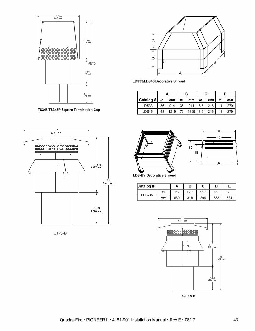
A
B
C
D
Catalog #A B C D
in. mm in. mm in. mm in. mmLDS33 36 914 36 914 8.5 216 11 279
LDS46 48 1219 72 1829 8.5 216 11 279
LDS33/LDS46 Decorative Shroud
Catalog # A B C D E
LDS-BVin. 26 12.5 15.5 22 23
mm 660 318 394 533 584
ED
A
CB
LDS-BV Decorative Shroud
TS345/TS345P Square Termination Cap
CT-3-B
CT-3A-B
43Quadra-Fire • PIONEER II • 4181-901 Installation Manual • Rev E • 08/17
Quadra-Fire, a brand of Hearth & Home Technologies1915 West Saunders Street, Mt. Pleasant, Iowa 52641
www.quadrafire.com
Please contact your Quadra-Fire dealer with any questions or concerns.For the location of your nearest Quadra-Fire dealer, please visit www.quadrafire.com.
R
44 Quadra-Fire • PIONEER II • 4181-901 Installation Manual • Rev E • 08/17