INSTALLATION MANUAL · motor-manual crank shaft. Figure 2. Locating the screws that attach the main...
21
Toll Free: 1-800-563-4382 WWW.TRUSTRAM.COM INSTALLATION MANUAL Copyright 1996 Revision 1 – November 2004
Transcript of INSTALLATION MANUAL · motor-manual crank shaft. Figure 2. Locating the screws that attach the main...

Toll Free: 1-800-563-4382
WWW.TRUSTRAM.COM
INSTALLATION MANUALCopyright 1996
Revision 1 – November 2004

SECTION 1 - SITE PREPARATION
Page 1-1Rev. 1
1.1The Trus-T-Lift elevator requires a solid, smooth, and levelmounting surface with an area at least 12” larger than thelift itself (60” x 66” or 66” x 66” for an adjacent style lift).You should also make sure that the toe plate will land on asolid surface, this will require an addition 12” to 20” on theentrance side of the lift.The mounting surface must be solid enough to support thelift and it’s maximum rated load (a total of 880 lb.). A solidwood or concrete deck would be an acceptable mountingsurface.NOTE: The Trus-T-Lift ships with four 3/8” x 2 3/4”concrete wedge anchors.
1.2The travel wall is the wall below the upper entrance/exitpoint of the elevator (Fig. 1). This wall should be vertical,smooth, and free of gaps or protrusions for the entire traveldistance of the elevator.
1.3A 110 VAC 15A electrical receptacle must be providedwithin 6 feet of the tower side of the Trust-T-Lift.
** All lifts over 52” in travel shouldbe secured to the building foradditional support.
Figure 1. Typical installation site showing mountingsurface and travel wall.

SECTION 2 - ASSEMBLY
Page 2-1Rev. 1
2.1Position the base frame 3 1/2 inches from the travel walland in line with the upper entrance/exit (Fig. 1).
2.2Adjust the leveling screws to level the base frame (Fig. 2).NOTE: Do not install the anchors at this time.
.
Figure 1. Positioning the base frame.
Figure 2. Leveling screw, anchor locations and deckposition.
MATERIAL LIST PART #1. Base Frame FFCTB001

SECTION 2 - ASSEMBLY
Page 2-2Rev. 1
2.3Secure the main tower to a furniture dolly for ease ofhandling .
2.4Position 2” Styrofoam packing blocks in the positionsindicated in preparation for installing the main tower(Fig 4).
2.5Using the furniture dolly, move the main tower into positionover the mounting bolts. The front half of the tower baseangles should be supported by the 2” Styrofoam packingblocks (Fig. 4).
2.6Carefully remove the dolly from the main tower and lowerthe back half of the tower onto the mounting bolts (Fig. 5).Remove the 2” Styrofoam packing blocks and lower thefront half of the tower on to the mounting bolts (Fig. 6).Install and tighten the nuts for the tower base angles.Once the tower is secure to the base frame and is inposition remove the guide frame hold down strap (Fig. 3).!!DO NOT MOVE THE LIFT FROM THE GUIDE FRAMEOR CARRIAGE ONCE THE HOLD DOWN STRAP HASBEEN REMOVED.
Figure 3. Location of the carriage hold down strap.
Figure 4. Supporting the front of the main tower onStyrofoam packing blocks.
MATERIAL LIST PART #1. Base frame FFCTB0012. 2” Styrofoam packing blocks3. Main tower assembly4. 1/2 - 13 N.C. flange nut
Figure 5. Installing the nuts on the main towermounting bolts.
Figure 6. Lowering the rear of the main tower on tothe mounting bolts.

SECTION 2 - ASSEMBLY
Page 2-3Rev. 1
2.7Plug the main tower in to a 110 VAC electrical outlet andraise guide frame to a height of at least 14 inches (FIG. 7).
2.8Slide the carriage in to place on the base frame (Fig. 8), becareful not to scratch the base frame.Hint!! Use packing foam from shipping crate to protectbase frame when installing carriage.
2.9Lower the guide frame to line up bolt holes on the carriage,and install the bolts (Fig. 9).NOTE: Do not over tighten the bolts. Figure 7. Raising the guide frame to allow room to
install the carriage.
MATERIAL LIST PART #1. Carriage FFCTC0012. 1/2 - 13 x 3 bolt
Figure 8. Sliding the carriage in to position.
Figure 9. Bolting the carriage to the guide frame.

SECTION 2 - ASSEMBLY
Page 2-4Rev. 1
2.10Install the toe plate guide on the same side as the toe plateand tighten all the screws (Fig. 10).
2.11Install the handrail and tighten the bolts (Fig. 11).
Figure 10. Installing the toe plate guide.
MATERIAL LIST PART #1. Toe plate guide/grab rail FFCTC0312. 10-32 x 3/4 lg. pan head screw3. Handrail FFBTC0074. 5/16 N.C. x 1 3/4 lg. bolt c/w lock nut&washer
Figure 11. Installing the handrail.

SECTION 2 - ASSEMBLY
Page 2-5Rev. 1
2.12Raise the carriage to a comfortable working height, installthe toe plate and tighten all the bolts (Fig. 12).
2.13Install the toe plate roller lever on to the toe plate (Fig. 13).
MATERIAL LIST PART #1. Toe plate assembly2. 3/8 N.C. x 3/4 lg. bolt c/w lock nut3. Toe plate roller lever4. 10 - 32 x 3/4 lg. pan hd. mach. screw
Figure 12. Installing the toe plate.
Figure 13. Installing the toe plate roller lever.

SECTION 2 - ASSEMBLY
Page 2-6Rev. 1
2.14Unfasten one side of the toe plate roller strap (Fig. 14).Loop the strap around the toe plate guide and re-attach itto the toe plate roller lever (Fig. 15).NOTE: Do not over tighten the bolts.
Figure 14. Installing the toe plate roller strap.
MATERIAL LIST PART #1. Toe plate roller lever2. Toe plate roller strap3. Toe plate guide/grab bar.
Figure 15. Re-attaching the toe plate roller strap afterwrapping it around the guide bar.

SECTION 2 - ASSEMBLY
Page 2-7Rev. 1
2.15Level the deck with the two leveling screws provided (Fig.16).
2.16Adjust the leveling screws in the base frame so that thecarriage runs evenly along the travel wall (Fig. 2).
2.17Install and tighten the 3/8 x 2 /34 concrete wedge anchors(assuming a concrete base is used) (Fig. 2).
2.18The upper limit adjusting bracket is located on the rightside of the front cover plate of the main tower. Use aRobertson screwdriver to loosen and slide this bracket untilyou achieve the correct height (Fig. 17). Caution: Do notdrop the upper limit adjusting bracket down the shaft, it isvery difficult to retrieve.
Figure 16. Partial cut-away view showing thelocation of the leveling screws.
Figure 17. Locating the upper limit adjustingbracket.
IMPORTANT:ONCE INSTALLATION IS COMPLETE – REMOVEFRONT PLASTIC COVER PANEL AND INSPECTDRIVE NUTS TO INSURE THEY ARE BOTH IN THECHANNEL AND THE SHEAR SCREW IS NOTBROKEN

SECTION 2 - ASSEMBLY
Page 2-8Rev. 1
2.19Call stations, Upper Gates and Interlocks terminate at the outside junction box on the bottom left side of the tower (fig.18).
Remove the cover from the junction box, inside there is a cable with individual wires labeled with numbered tags
Number tags are also on the end of the wires coming from the option to be hooked up
Mount the call station, Upper gate and/or interlocks into their respective positions
Run the wires from each option to the outside junction box through conduit.
Using the wire nuts provided match the numbers on the wires together to complete the terminations
Figure 18. Wiring the call buttons into the outside junction box.
SECTION 3 - MAINTENANCE
Page 3-1Rev. 1
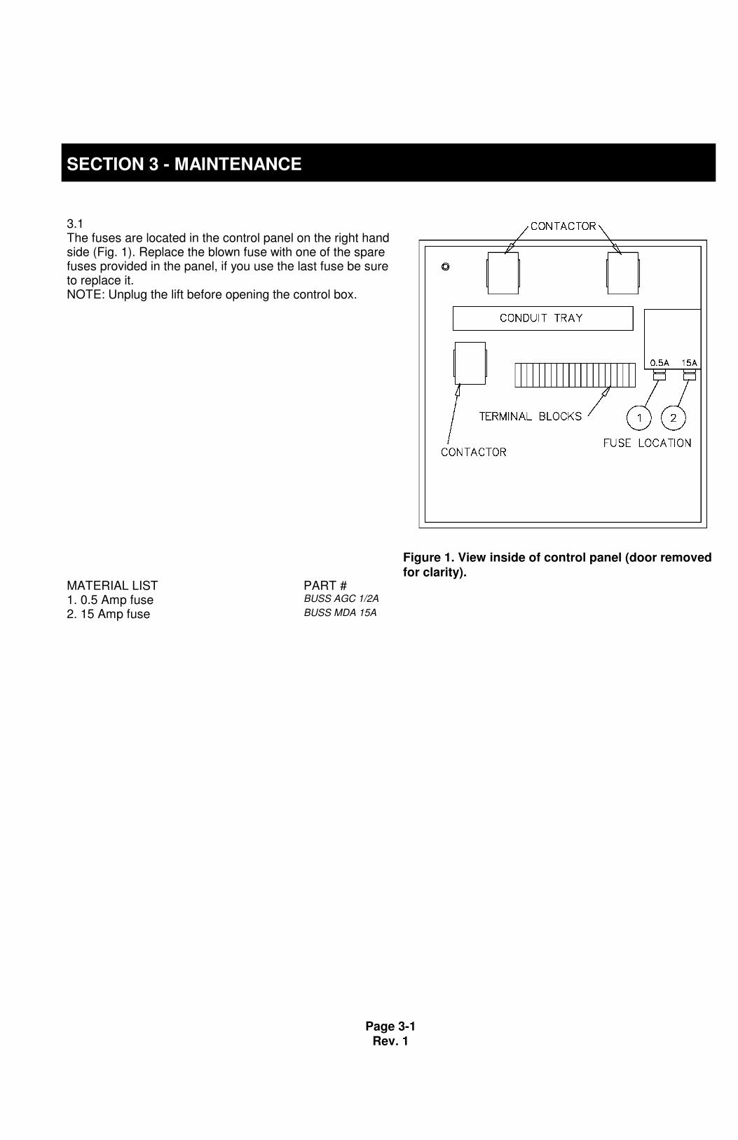
3.1The fuses are located in the control panel on the right handside (Fig. 1). Replace the blown fuse with one of the sparefuses provided in the panel, if you use the last fuse be sureto replace it.NOTE: Unplug the lift before opening the control box.
Figure 1. View inside of control panel (door removedfor clarity).
MATERIAL LIST PART #1. 0.5 Amp fuse BUSS AGC 1/2A
2. 15 Amp fuse BUSS MDA 15A

SECTION 3 - MAINTENANCE
Page 3-2Rev. 1
3.2 The Trus<T>Lift should be inspected and maintainedannually. (See Drive Nut Safety Bulletin) In addition toinspecting the drive nuts, the drive screw should becleaned and re-lubricated at least once a year. In order toaccess the screw drive you must remove the main frontpanel (Fig. 2 & 3). The gear box is oil filled and should bechecked for leaks. Remove the top breather plug to checkthat the gear box fluid level is at least to the center of themotor-manual crank shaft.
Figure 2. Locating the screws that attach the main frontpanel.
Figure 3. Gear reducer location.

SECTION 3 - MAINTENANCE
Page 3-3Rev. 1
3.2In order to lubricate the drive screw you must remove themain front panel and a carriage guide frame panel (Fig. 2 &4). Liberally apply grease on the drive screw by hand,replace the covers and run the lift up and down a fewtimes.
Figure 4. Applying grease to the drive screw.

SECTION 3 - MAINTENANCE
Page 3-4Rev. 1
3.3In the event that the lifting nuts move down past the lower limit switch you may hear a loud snap indicating that theshear pin has broken. Use the following procedure to put them back into place (Fig. 5):
• Remove the carriage from the guide frame (make sure to remove the toe plate roller strap).
• Remove the main front panel from the tower and the center panel from the guide frame.
• Lift the guide frame up about 12 inches and brace in place.
• Spin the lifting nuts into place as per Fig. 5, make sure that the flat sides of the lifting nuts fit between theguide frame bracket angles.
• Lower the guide frame until it is supported by the upper lifting nut.
• Make sure that the lower travel limit switch is in the relaxed position and is below the lifting nuts. See DriveNut Safety Bulletin for installation of the back up safety bracket.
• Replace the broken 10-32 x 1/2º Lg. Pan Head screw shear pin.
• Replace the covers and the carriage.
Figure 5. Adjusting the lifting nuts.

SECTION 4 – TEMPORARY INSTALLATIONS
Page 4-1Rev. 1
4.1An alternate installation method, which is ideal fortemporary installations, is to provide 2 - 2º x 10º roughlumber supports that are embedded in 2º of gravel or sand.(Fig. 1 & Fig. 2).
** All lifts over 52” in travel shouldbe secured to the building foradditional support.
Figure 1. Alternate installation with 2 - 2” x 10” roughlumber supports.
Figure 2. Placing the supports into the preparedgravel or sand bed.

APPENDIX
Page A-1Rev. 1
CONTENTS
• Exploded view of Trus<T>Lift
• Drive nut safety bulletin
• Troubleshooting guide
• Schematics and wiring diagrams


10812 – 181 Street, Edmonton, Alberta T5S 1K8 •780.484.4776 • 1.800.563.4382 • Fax 780.486.2920 • www.trustram.com
�������������� �����������������
�
The following Safety Bulletin is to inform all Trus<T>Lift installers & owners of acritical safety check of the drive nuts that support the Trus<T>Lift platform. Thefollowing safety check must be performed annually on every Trus<T>Lift.
The top bronze drive nut is the main support that raises and lowers the platform.It is made from a low friction bronze bushing material that will wear over time.The lower nut is a safety back-up nut made from the same material intended toprotect the platform from freefall should the main nut fail. It must not be used asa main drive nut.
• Bronze drive nuts should be spacedapart by ¾”.
• Both the drive nut and the back-up nutshould be positioned in the channel asseen in the photo.
• The Lower drive nut includes a back upsafety bracket (red plate as pictured).
• The back up safety bracket is includedon all lifts manufactured after May13/04 (serial # TS 13220 and up)
• The back up safety bracket can beeasily added to existing liftsmanufactured prior to May 13/04.
• The purpose of the safety back upplate is to indicate to the user when themain lifting nut has failed.
• If the main nut fails the lower back-upnut will move up ¾” resulting in thelower limit switch becoming activatedby the safety plate. The lift will onlyoperate in the up direction until twonew drive nuts have been installed.

Rev. 1 1
TRUS<T>LIFT TROUBLESHOOTING GUIDE
PROBLEM: “TRUS<T>LIFT DOES NOT RUN”
• First inspect manual operating button on M3 relay:
- Button is in → Go to “Not Running Up or Not Running Down” Section- Button is not in:
1. Check fuses & power supply with volt meter
• 0 ohms resistance across good fuses
• 110-120 Volts across N (Neutral) and terminal #1
2. If power and fuses are OK, using a 12 inch insulated jumperwire, touch ends of wire to screws #1 & #2 of terminal strip.Watch the M3 operating button.
3. If the button comes in, the UPPER FINAL LIMIT is either
activated or it is faulty. → Inspect the UPPER FINAL LIMIT**(If your lift has a CAR GATE, UPPER LANDING GATE, MIDLANDING GATE or LOWER LANDING GATE, also check thatall Gate and lock contacts are closed)**
4. If the button does not come in, using the insulated jumper wire,touch ends to screws #2 & #3 of terminal strip.
5. If the button comes in the EMERGENCY STOP isdepressed or the CONTACT BLOCK of EMERGENCY STOP
may be sticking. →Inspect the EMERGENCY STOP
6. If the button does not come in, using the insulated jumper wire,touch ends to screws #1 & #3 of terminal strip.
7. If the button comes in, both EMERGENCY STOP andUPPER FINAL LIMIT**(and GATES) are activated.
8. If the button does not come in, using insulated jumper wiretouch screw #1 & M3A1. If the button comes in a control wirehas come loose, inspect wires at terminal #1, #2, #3, andM3A1. If the button does not come in the coil for M3 has failed.

Rev. 1 2
PROBLEM: “THE LIFT WILL GO UP BUT NOT DOWN”
• QUESTION: Does motor make a sound like it’s trying to start?
→ YES The BACKUP SAFETY NUT has come out and isjamming on bottom plate.SEE “RESETTING BACKUP NUT PROCEDURE” ininstallation manual.
→ NO Using a 12” insulated jumper wire, touch ends of wireon screw #4 & #5 on terminal strip - at sametime push the DOWN PUSHBUTTON.
1. If the lift runs then LOWER LIMIT SWITCH iseither activated by the BACKUP SAFETY NUT or
it has failed. →Remove front cover & inspectswitch. **(If your lift has a SAFETY PAN alsocheck that all 5 safety pan switches are notactivated and that the safety pan plug is in andlocked)**
2. If lift does not run, then using a 12” insulatedjumper wire, touch ends of wire on screws # 5 &
#7 of the terminal strip.
→ If lift runs, then DOWN PUSHBUTTON orKEY SWITCH are not operating properly –remove & inspect
→ If lift does not run, then touch ends ofinsulated jumper wire to screws #4 & #7 of theterminal strip.
1. If lift runs, then both the LOWERLIMIT SWITCH, DOWNPUSHBUTTON or KEY SWITCH
have failed → inspect
2. If lift does not run, either coil for M1has failed or M2 NC Contact hasfailed. Jump from #4 to M1A1, if liftruns then replace the M2. If lift doesnot run then replace the M1 and/orcheck power supply again.

Rev. 1 3
PROBLEM: “LIFT WILL GO DOWN BUT NOT UP”
• Using a 12” insulated jumper wire, touch ends of wire to screws #4 & #6 ofterminal strip and press UP PUSHBUTTON.
1. If lift goes up, then the UPPER LIMIT SWITCH is either stuck in the
on position or has failed. → Remove front cover and inspect
2. If lift does not move, then using the jumper wire, touch ends to screws#6 & #8 of the terminal strip.
• If lift goes up then UP PUSHBUTTON or KEY SWITCH is not
operating properly → Inspect
• If lift does not move, using the jumper wire touch ends toscrews #4 & #8 of terminal strip.
→ If lift goes up, then either UP PUSHBUTTON or KEYSWITCH and UPPER LIMIT SWITCH have failed
→ Inspect
→ If lift doesn’t go up, either coil for M2 has failed or M1 NCcontact has failed. Jump from #4 to M2A1, if lift runsreplace the M1. If lift still does not run, replace M2 andcheck power supply again.
***NOTE The above Trouble Shooting guide pertains to basic operationproblems. For additional problems not covered in this guide please contact RAMtechnical support at 1-800-563-4382 if calling from within USA or Canada /780-484-4776 if calling from outside USA or Canada.