Installation Manual - Motoman · For connecting the server Unified Automations UAExpert is used as...
48
ROBOTICS Variable "Auftragsnummer" not defined. Yaskawa OPC UA Server V 1.0 Installation Manual 189623-1CD 1
Transcript of Installation Manual - Motoman · For connecting the server Unified Automations UAExpert is used as...

ROBOTICS
Variable "Auftragsnummer" not defined.Yaskawa OPC UA Server V 1.0
Installation Manual
189623-1CD1

© Copyright 2019This documentation (or parts of it) must not be reproduced or made available to third parties withoutthe express approval of YASKAWA Europe "Robotics Division GmbH”.We have checked the content of this publication for compatibility with the hardware described.Nevertheless, discrepancies cannot be ruled out. Therefore, we cannot guarantee full compliance.However, the information given in this publication is checked regularly and any necessary correctionswill be made in subsequent editions.Subject to technical modifications.
Created on: 2019-11Revision: 02Document number: E1102000291GB02 Author: DD\WOE
Modifications made:Rev. 01: Revised version of the original OPC UA Server ManualRev. 02: Revision of the chapters 3 "OPC UA Server setup" and 6.3 "Introduction to the OPCUA Config Editor"
Table of contents
Table of contents
1 Introduction . . . . . . . . . . . . . . . . . . . . . . . . . . . . . . . . . . . . . . . . . . . . . . . . . . . . . . . . . . . . . . . . . 4
2 Implementation details . . . . . . . . . . . . . . . . . . . . . . . . . . . . . . . . . . . . . . . . . . . . . . . . . . . . . . . . 5
3 OPC UA Server setup . . . . . . . . . . . . . . . . . . . . . . . . . . . . . . . . . . . . . . . . . . . . . . . . . . . . . . . . . 63.1 Install OPC UA server . . . . . . . . . . . . . . . . . . . . . . . . . . . . . . . . . . . . . . . . . . . . . . . . . . . . . 6
3.1.1 Requirements . . . . . . . . . . . . . . . . . . . . . . . . . . . . . . . . . . . . . . . . . . . . . . . . . . . . . 63.1.2 Load the OPCUA.out application file . . . . . . . . . . . . . . . . . . . . . . . . . . . . . . . . . . . 73.1.3 Server certificate. . . . . . . . . . . . . . . . . . . . . . . . . . . . . . . . . . . . . . . . . . . . . . . . . . . 8
3.2 Licensing OPC UA server . . . . . . . . . . . . . . . . . . . . . . . . . . . . . . . . . . . . . . . . . . . . . . . . . . 93.2.1 Checking for a valid license . . . . . . . . . . . . . . . . . . . . . . . . . . . . . . . . . . . . . . . . . . 93.2.2 Request a license file from Yaskawa Europe . . . . . . . . . . . . . . . . . . . . . . . . . . . . 103.2.3 License activation . . . . . . . . . . . . . . . . . . . . . . . . . . . . . . . . . . . . . . . . . . . . . . . . . 11
4 Connecting OPC UA Server on port 16448 . . . . . . . . . . . . . . . . . . . . . . . . . . . . . . . . . . . . . . 13
5 OPC UA Address space / Information model . . . . . . . . . . . . . . . . . . . . . . . . . . . . . . . . . . . . . 155.1 General overview . . . . . . . . . . . . . . . . . . . . . . . . . . . . . . . . . . . . . . . . . . . . . . . . . . . . . . . 15
5.1.1 MotionDevices and controllers . . . . . . . . . . . . . . . . . . . . . . . . . . . . . . . . . . . . . . . 155.1.2 ProzessData . . . . . . . . . . . . . . . . . . . . . . . . . . . . . . . . . . . . . . . . . . . . . . . . . . . . . 165.1.3 Methods . . . . . . . . . . . . . . . . . . . . . . . . . . . . . . . . . . . . . . . . . . . . . . . . . . . . . . . . 16
5.2 NodeSet . . . . . . . . . . . . . . . . . . . . . . . . . . . . . . . . . . . . . . . . . . . . . . . . . . . . . . . . . . . . . . 19
6 Configuration file OPCCONFIG.JBI . . . . . . . . . . . . . . . . . . . . . . . . . . . . . . . . . . . . . . . . . . . . . 276.1 Configuration default setting . . . . . . . . . . . . . . . . . . . . . . . . . . . . . . . . . . . . . . . . . . . . . . . 276.2 Basic structure . . . . . . . . . . . . . . . . . . . . . . . . . . . . . . . . . . . . . . . . . . . . . . . . . . . . . . . . . 27
6.2.1 AppSettings . . . . . . . . . . . . . . . . . . . . . . . . . . . . . . . . . . . . . . . . . . . . . . . . . . . . . 286.2.2 VendorSettings . . . . . . . . . . . . . . . . . . . . . . . . . . . . . . . . . . . . . . . . . . . . . . . . . . . 33
6.3 Introduction to the OPCUA Config Editor . . . . . . . . . . . . . . . . . . . . . . . . . . . . . . . . . . . . . 366.3.1 Requirements . . . . . . . . . . . . . . . . . . . . . . . . . . . . . . . . . . . . . . . . . . . . . . . . . . . . 366.3.2 App settings . . . . . . . . . . . . . . . . . . . . . . . . . . . . . . . . . . . . . . . . . . . . . . . . . . . . . 366.3.3 Editing ProcessData . . . . . . . . . . . . . . . . . . . . . . . . . . . . . . . . . . . . . . . . . . . . . . . 376.3.4 Editing DeviceInfo. . . . . . . . . . . . . . . . . . . . . . . . . . . . . . . . . . . . . . . . . . . . . . . . . 386.3.5 Editing SystemInfo . . . . . . . . . . . . . . . . . . . . . . . . . . . . . . . . . . . . . . . . . . . . . . . . 40
6.4 Information for manual editing . . . . . . . . . . . . . . . . . . . . . . . . . . . . . . . . . . . . . . . . . . . . . 41
7 Secured connections . . . . . . . . . . . . . . . . . . . . . . . . . . . . . . . . . . . . . . . . . . . . . . . . . . . . . . . . 427.1 Encrypted connections . . . . . . . . . . . . . . . . . . . . . . . . . . . . . . . . . . . . . . . . . . . . . . . . . . . 42
7.1.1 Preparing certificates . . . . . . . . . . . . . . . . . . . . . . . . . . . . . . . . . . . . . . . . . . . . . . 427.2 Authentication . . . . . . . . . . . . . . . . . . . . . . . . . . . . . . . . . . . . . . . . . . . . . . . . . . . . . . . . . . 44
7.2.1 Files to add user settings . . . . . . . . . . . . . . . . . . . . . . . . . . . . . . . . . . . . . . . . . . . 44
8 Appendix . . . . . . . . . . . . . . . . . . . . . . . . . . . . . . . . . . . . . . . . . . . . . . . . . . . . . . . . . . . . . . . . . . 458.1 Third party licenses. . . . . . . . . . . . . . . . . . . . . . . . . . . . . . . . . . . . . . . . . . . . . . . . . . . . . . 45
8.1.1 OPC UA Server . . . . . . . . . . . . . . . . . . . . . . . . . . . . . . . . . . . . . . . . . . . . . . . . . . 458.1.2 OPCUA Config Editor . . . . . . . . . . . . . . . . . . . . . . . . . . . . . . . . . . . . . . . . . . . . . . 45
9 Imprint . . . . . . . . . . . . . . . . . . . . . . . . . . . . . . . . . . . . . . . . . . . . . . . . . . . . . . . . . . . . . . . . . . . . 46
3
Introduction
1 IntroductionOPC Unified Architecture (OPC UA) is a machine to machine communication protocol forindustrial automation developed by the OPC Foundation. It has already become the defacto standard for the automation market and Industry 4.0.Advantages of OPC UA:• Platform independence and scalability Ensures the seamless flow of information among
devices from multiple vendors.• Robust security Authentication and encryption capabilities for data protection.• A sophisticated information model Defines any model from simple to complex.Yaskawa’s OPC UA server is an optional function which extends the controller by the OPCUA communication protocol to get it ready for industry 4.0. The information model usedimplements the VDMA’s Robotics companion specification 1.0, which was created by theVDMA Robotics Initiative. This is a working group within VDMA robotics where Yaskawawas also actively involved alongside other robotics vendors.Yaskawa’s OPC UA server provides the following functionalities and advantages:
• Server runs on the controller using its standard ethernet interface (no additionalhardware is required).
• Implements basic OPC UA functionalities (Encryption, Authentication, Subscriptions,Methods,...).
• Structured view of the robot system.• Read, write access to robot data (Variables, IO’s).• Access to maintenance data.• Information model can be expanded by custom data.• Methods for remote control of the robot (Servo, JobStart, …).For connecting the server Unified Automations UAExpert is used as the client throughoutthis document.
1 - 4
Implementation details
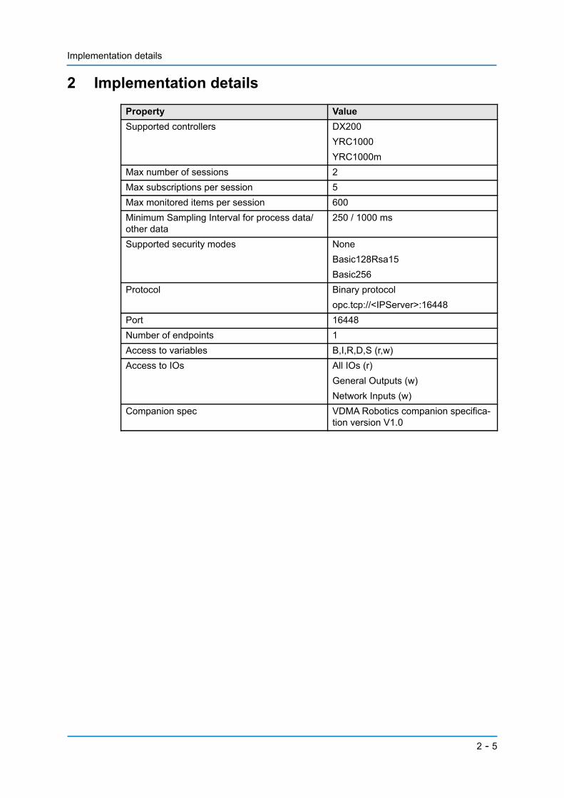
2 Implementation detailsProperty ValueSupported controllers DX200
YRC1000YRC1000m
Max number of sessions 2Max subscriptions per session 5Max monitored items per session 600Minimum Sampling Interval for process data/other data
250 / 1000 ms
Supported security modes None Basic128Rsa15 Basic256
Protocol Binary protocol opc.tcp://<IPServer>:16448
Port 16448Number of endpoints 1Access to variables B,I,R,D,S (r,w)Access to IOs All IOs (r)
General Outputs (w) Network Inputs (w)
Companion spec VDMA Robotics companion specifica-tion version V1.0
2 - 5
OPC UA Server setup
3 OPC UA Server setupThis chapter describes the installation of the OPC UA Server. Normally the controller isalready delivered with the OPC UA function activated. In this case this chapter can beskipped.
3.1 Install OPC UA server
3.1.1 Requirements
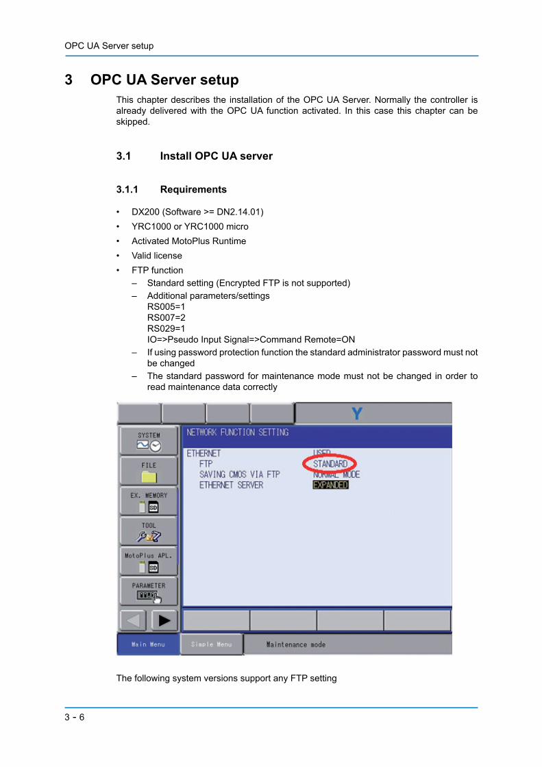
• DX200 (Software >= DN2.14.01)• YRC1000 or YRC1000 micro• Activated MotoPlus Runtime• Valid license• FTP function
– Standard setting (Encrypted FTP is not supported)– Additional parameters/settings
RS005=1RS007=2RS029=1IO=>Pseudo Input Signal=>Command Remote=ON
– If using password protection function the standard administrator password must notbe changed
– The standard password for maintenance mode must not be changed in order toread maintenance data correctly
The following system versions support any FTP setting
3 - 6
OPC UA Server setup
• YRC1000 with software >= 2.60.10. Set S2C1402 = 3• YRC1000 micro with software >= 2.10.00. Set S2C1402 = 3
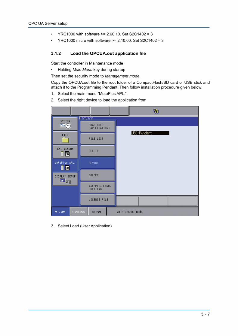
3.1.2 Load the OPCUA.out application file
Start the controller in Maintenance mode• Holding Main Menu key during startupThen set the security mode to Management mode.Copy the OPCUA.out file to the root folder of a CompactFlash/SD card or USB stick andattach it to the Programming Pendant. Then follow installation procedure given below:1. Select the main menu “MotoPlus APL.”.2. Select the right device to load the application from
3. Select Load (User Application)
3 - 7
OPC UA Server setup
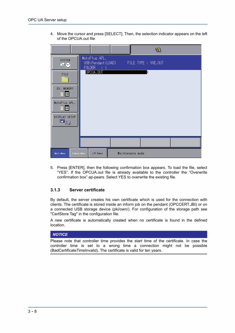
4. Move the cursor and press [SELECT]. Then, the selection indicator appears on the leftof the OPCUA.out file
5. Press [ENTER], then the following confirmation box appears. To load the file, select“YES”. If the OPCUA.out file is already available to the controller the “Overwriteconfirmation box” ap-pears. Select YES to overwrite the existing file.
3.1.3 Server certificate
By default, the server creates his own certificate which is used for the connection withclients. The certificate is stored inside an inform job on the pendant (OPCCERT.JBI) or ona connected USB storage device (pki/own/). For configuration of the storage path see"CertStore Tag" in the configuration file.A new certificate is automatically created when no certificate is found in the definedlocation.
NOTICEPlease note that controller time provides the start time of the certificate. In case thecontroller time is set to a wrong time a connection might not be possible(BadCertificateTimeInvalid). The certificate is valid for ten years.
3 - 8
OPC UA Server setup
3.2 Licensing OPC UA server
3.2.1 Checking for a valid license
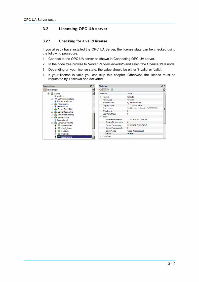
If you already have installed the OPC UA Server, the license state can be checked usingthe following procedure:1. Connect to the OPC UA server as shown in Connecting OPC UA server.2. In the node tree browse to Server.VendorServerInfo and select the LicenseState node.3. Depending on your license state, the value should be either ‘invalid’ or ‘valid’.4. If your license is valid you can skip this chapter. Otherwise the license must be
requested by Yaskawa and activated.
3 - 9

OPC UA Server setup
3.2.2 Request a license file from Yaskawa Europe
Note: (Only if purchased through YASKAWA Europe)If a license file is already to hand, these steps can be skipped.On the controller:• Upgrade security level to Management.• Touch [System Info] > [Network Service].• Write down the MAC address displayed on the pendant for the network card.
(In case of YRC1000 use the MAC of the first Network card)
• Send the MAC address along with the purchase information [email protected].
You will receive the “MotoPlusApp.lic” file via email.
3 - 10
OPC UA Server setup
3.2.3 License activation
3.2.3.1 DX200/YRC1000
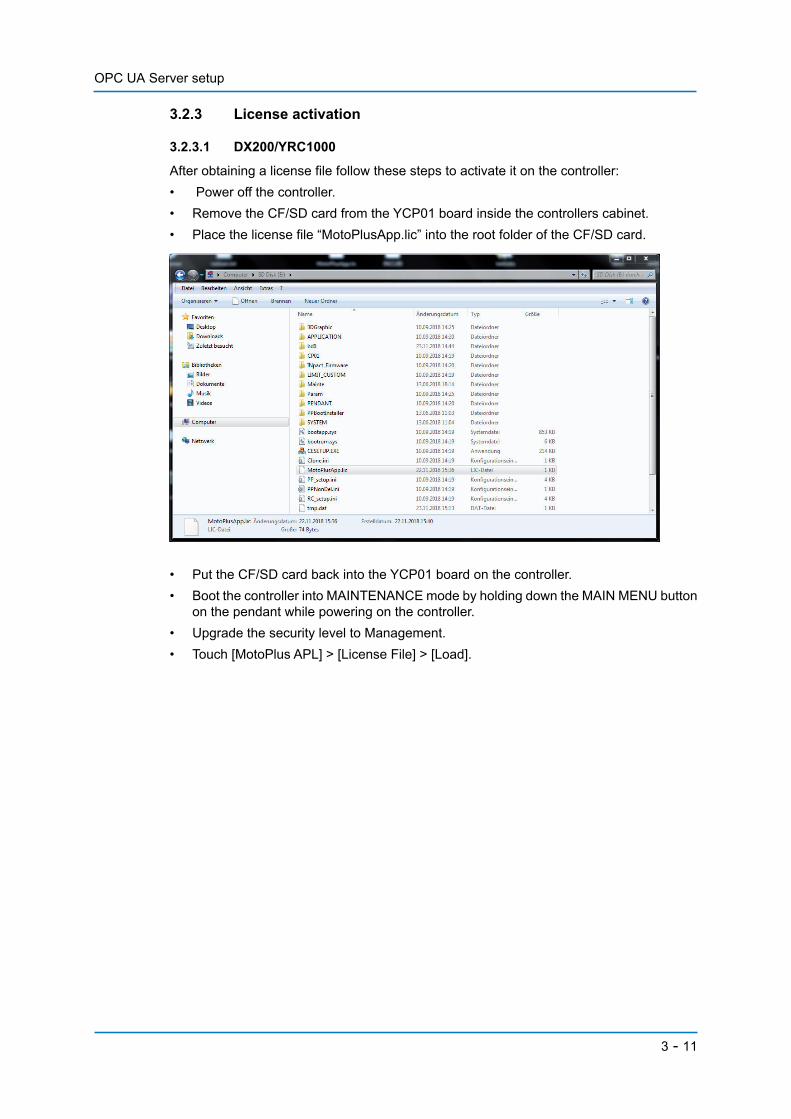
After obtaining a license file follow these steps to activate it on the controller:• Power off the controller.• Remove the CF/SD card from the YCP01 board inside the controllers cabinet.• Place the license file “MotoPlusApp.lic” into the root folder of the CF/SD card.
• Put the CF/SD card back into the YCP01 board on the controller.• Boot the controller into MAINTENANCE mode by holding down the MAIN MENU button
on the pendant while powering on the controller.• Upgrade the security level to Management.• Touch [MotoPlus APL] > [License File] > [Load].
3 - 11

OPC UA Server setup
• Confirm the dialog.• Perform CPU reset and boot into normal mode.The OPC UA license is now activated.
3.2.3.2 YRC1000 micro
• Place the license file “MotoPlusApp.lic” onto the root of a usb or sd card.• Insert the memory card into the teach pendant.• Boot the controller into normal mode.• Elevate the security mode to ‘MANAGEMENT’ (9’s).• Select ‘EX. MEMORY’.• Ensure the proper device is selected.• Select ‘LOAD’, ‘USER FILE’.• Select/load the license file “MotoPlusApp.lic” from the list.
3 - 12
Connecting OPC UA Server on port 16448
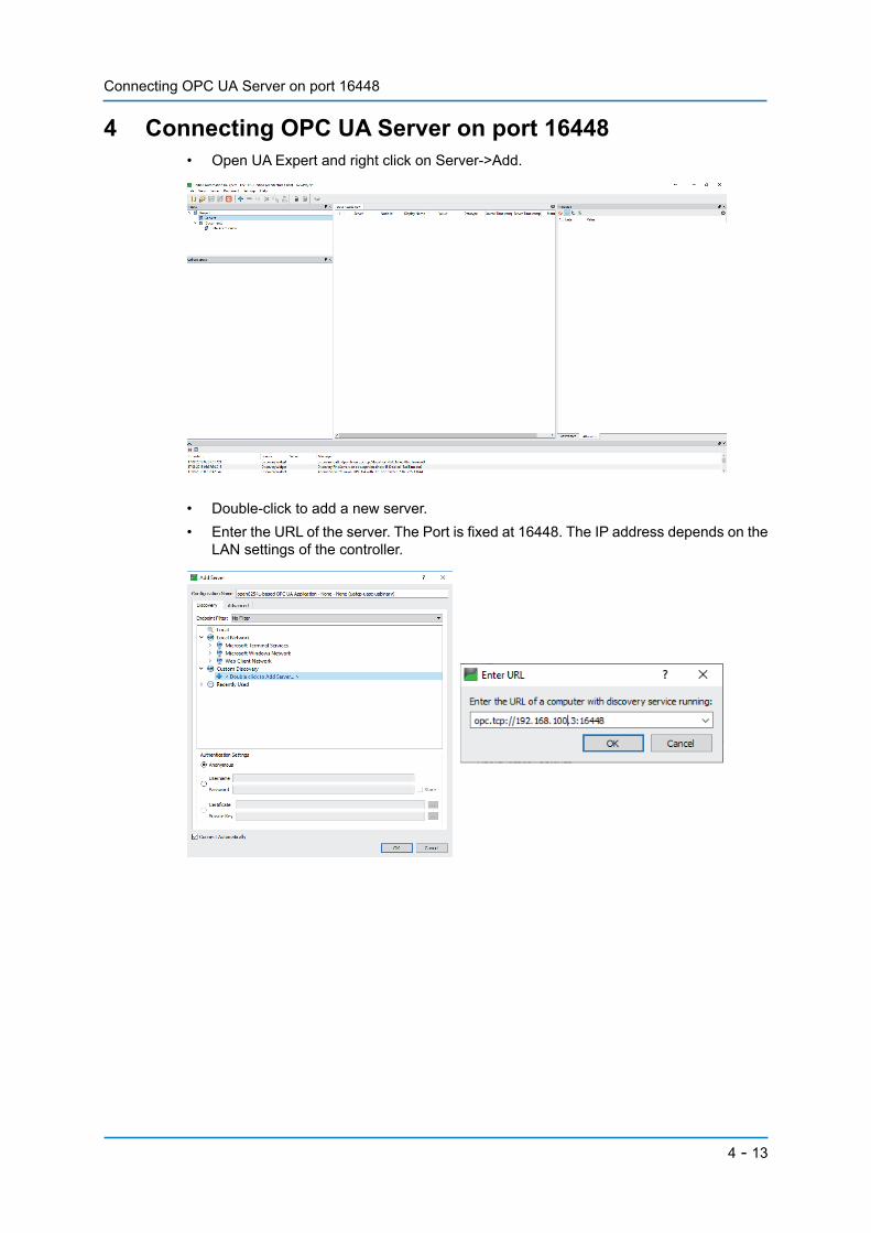
4 Connecting OPC UA Server on port 16448 • Open UA Expert and right click on Server->Add.
• Double-click to add a new server.• Enter the URL of the server. The Port is fixed at 16448. The IP address depends on the
LAN settings of the controller.
4 - 13

Connecting OPC UA Server on port 16448
• Navigate the available server endpoints. Depending on the configuration, secured ornon-secured endpoints are available. For an easy start select None (no encryption).
• Server is added. If not already connected, right-click on the server to connect.
You are now connected to the Yaskawa OPC UA Server.
4 - 14

OPC UA Address space / Information model
5 OPC UA Address space / Information modelThe Address Space is based on VDMA’s Robotics Companion Specification. For furtherinformation please check this specification.
5.1 General overview
After successfully installing and activating your OPC UA Server, you will be able to browsethe OPC UA Address Space by using UA Expert.
5.1.1 MotionDevices and controllers
The root directory should look like this.Robot data is located inDeviceSet.MotionDeviceSystem.
A MotionDeviceSystem consists of one controller and depending on con-figuration 1..n MotionDevices.
Depending on the controller configu-ration, there can be more than one MotionDevice that stands for an inde-pendent motion device according to the VDMA Robotics spec. In our mod-el it can be a robot or a single axis (turntable, …).In the case of controller, there is al-ways only one available.
5 - 15
OPC UA Address space / Information model
5.1.2 ProzessData
5.1.3 Methods
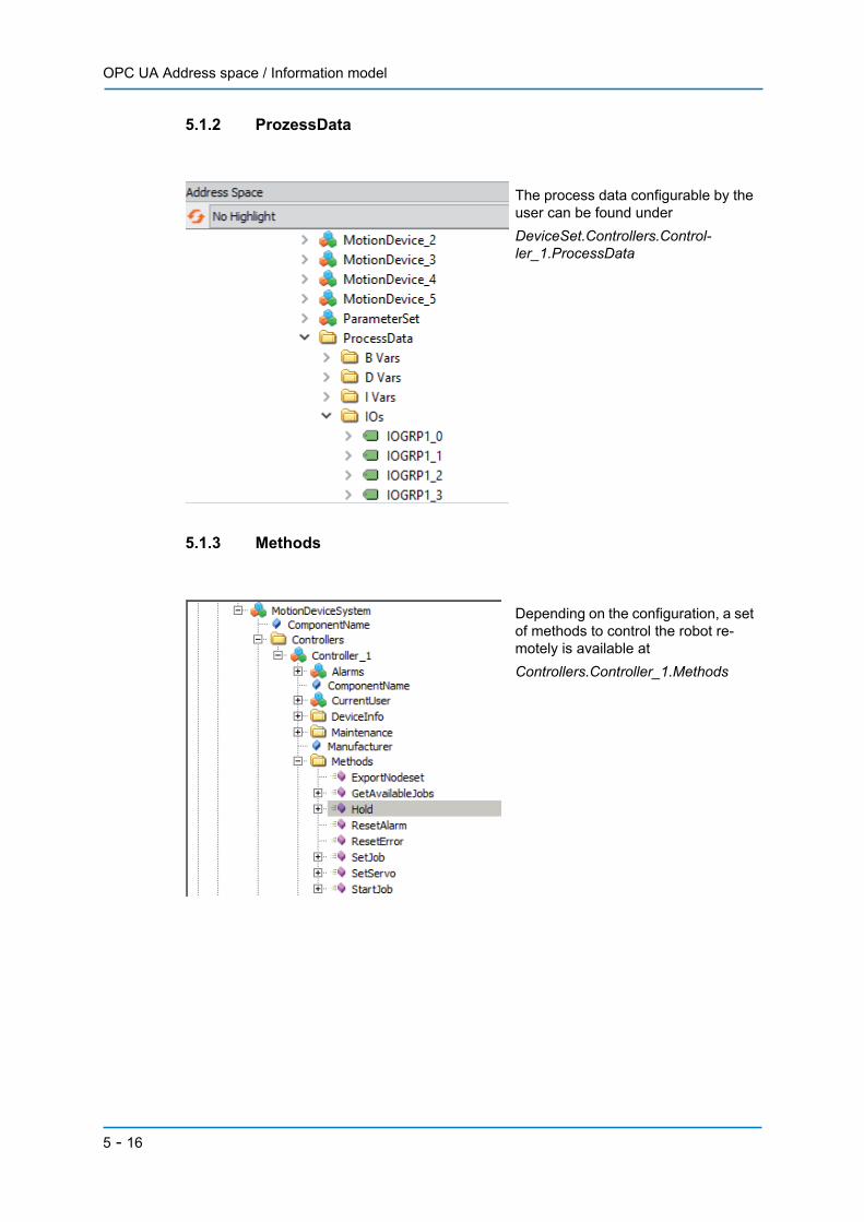
The process data configurable by the user can be found underDeviceSet.Controllers.Control-ler_1.ProcessData
Depending on the configuration, a set of methods to control the robot re-motely is available atControllers.Controller_1.Methods
5 - 16
OPC UA Address space / Information model
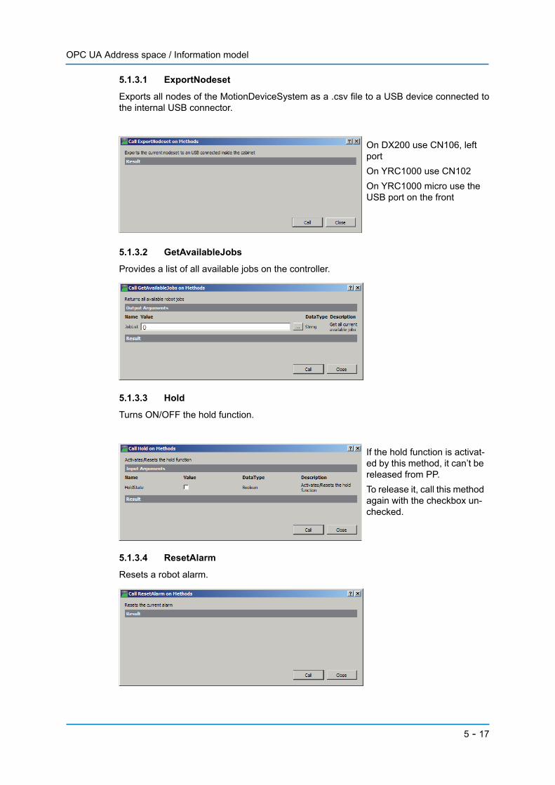
5.1.3.1 ExportNodeset
Exports all nodes of the MotionDeviceSystem as a .csv file to a USB device connected tothe internal USB connector.
5.1.3.2 GetAvailableJobs
Provides a list of all available jobs on the controller.
5.1.3.3 Hold
Turns ON/OFF the hold function.
5.1.3.4 ResetAlarm
Resets a robot alarm.
On DX200 use CN106, left portOn YRC1000 use CN102On YRC1000 micro use the USB port on the front
If the hold function is activat-ed by this method, it can’t be released from PP. To release it, call this method again with the checkbox un-checked.
5 - 17
OPC UA Address space / Information model
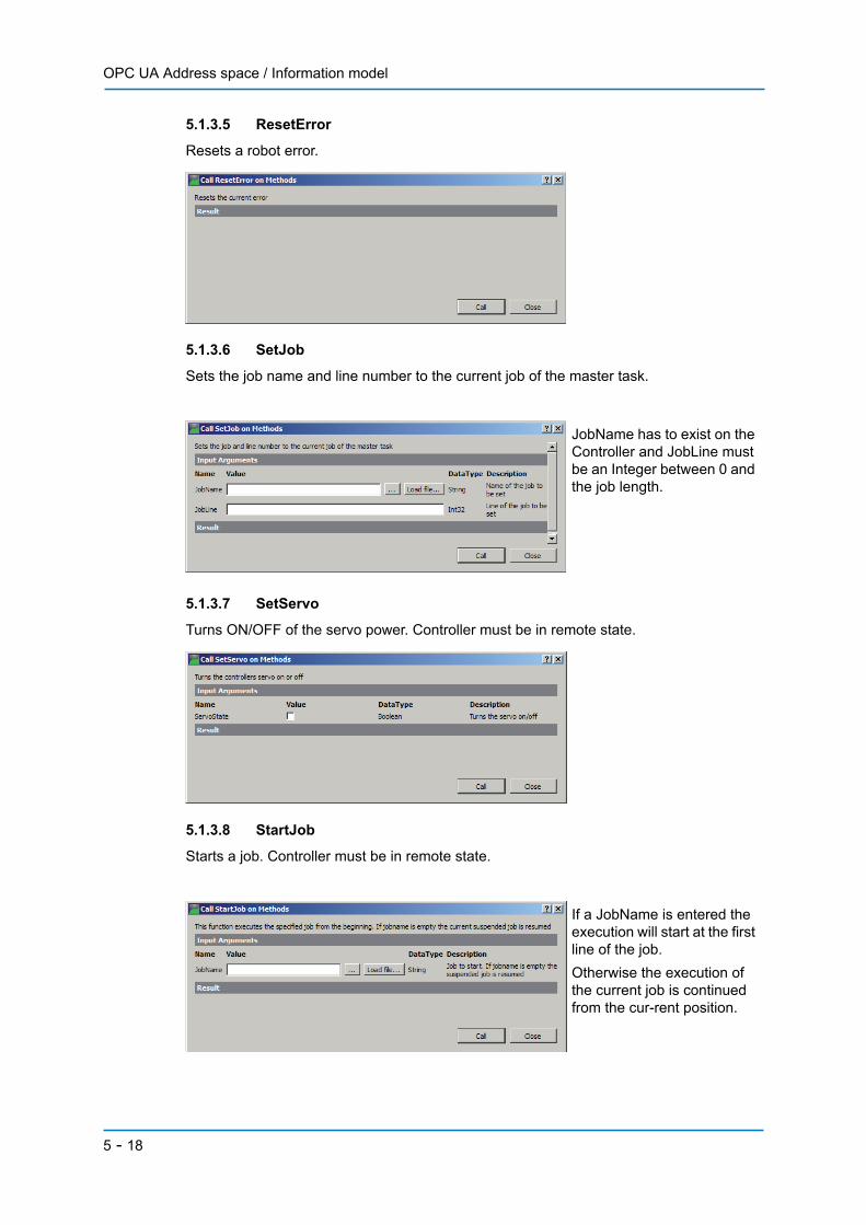
5.1.3.5 ResetError
Resets a robot error.
5.1.3.6 SetJob
Sets the job name and line number to the current job of the master task.
5.1.3.7 SetServo
Turns ON/OFF of the servo power. Controller must be in remote state.
5.1.3.8 StartJob
Starts a job. Controller must be in remote state.
JobName has to exist on the Controller and JobLine must be an Integer between 0 and the job length.
If a JobName is entered the execution will start at the first line of the job.Otherwise the execution of the current job is continued from the cur-rent position.
5 - 18

OPC UA Address space / Information model
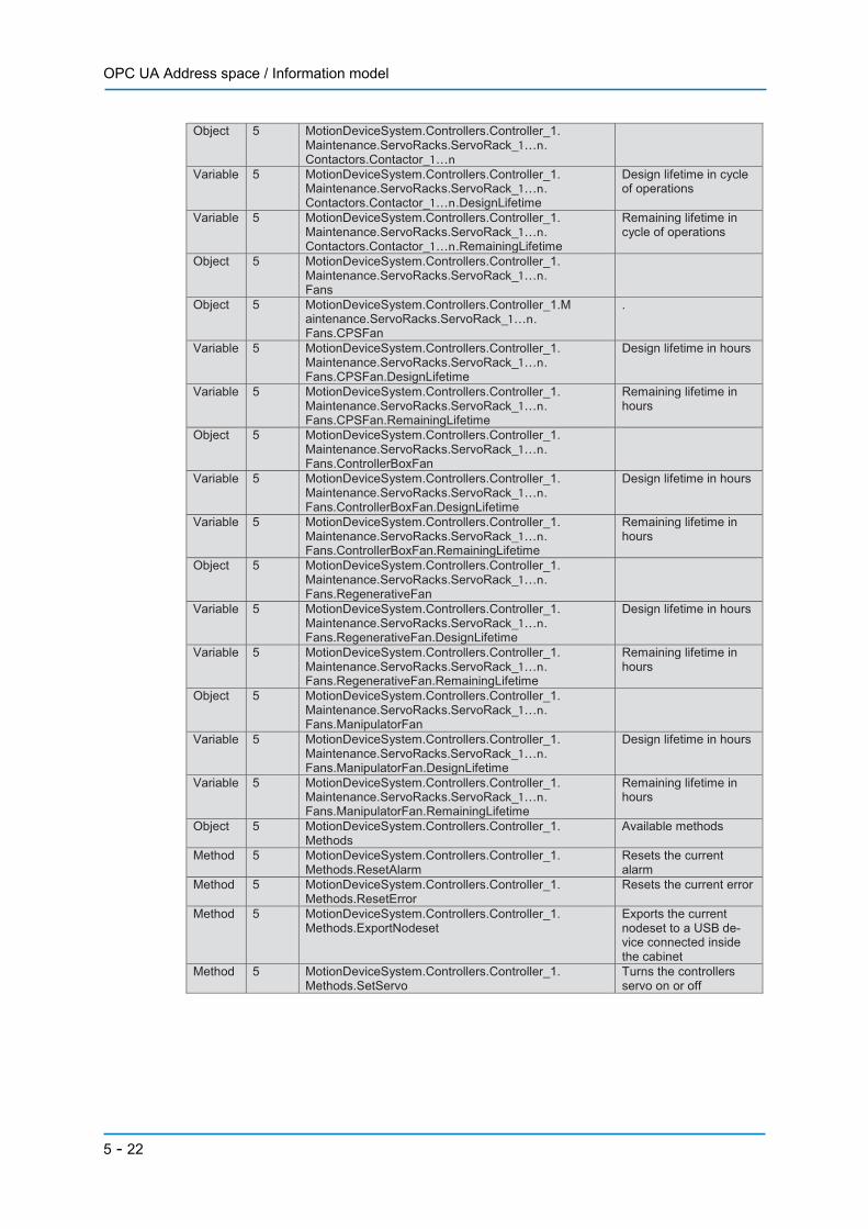
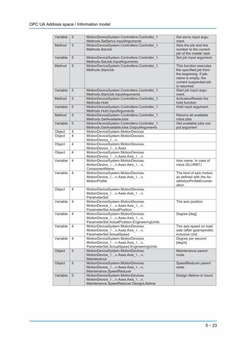
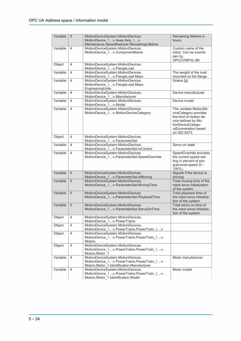
5.2 NodeSet
The following list provides an overview of the current used address space. Maintenancedata, number of MotionDevices and Axes might differ depending on controller and robotsetup.There are two namespaces used:• NS4 is used for nodes coming from the OPC UA for Robotics Companion Specification• NS5 is used for nodes that are specific to Yaskawa robots.
Type Name-space Path Description
Object 4 MotionDeviceSystem Variable 4 MotionDeviceSystem.ComponentName Name of the Motion
Device System. Can be overridden by OPCCONFIG.JBI
Object 4 MotionDeviceSystem.Controllers Contains the set of con-trollers in the motion device system. This is always 1.
Object 4 MotionDeviceSystem.Controllers.Controller_1 Variable 4 MotionDeviceSystem.Controllers.Controller_1.
ComponentName Name of the controller. Can be overridden by OPCCONFIG.JBI
Object 4 MotionDeviceSystem.Controllers.Controller_1. CurrentUser
Variable 4 MotionDeviceSystem.Controllers.Controller_1. CurrentUser.Level
The current logged in user level
Variable 4 MotionDeviceSystem.Controllers.Controller_1. Manufacturer
Controller vendor
Variable 4 MotionDeviceSystem.Controllers.Controller_1. Model
Controller model
Object 4 MotionDeviceSystem.Controllers.Controller_1. ParameterSet
Variable 4 MotionDeviceSystem.Controllers.Controller_1. ParameterSet.StartUpTime
The date and time of the last startup of the controller.
Variable 4 MotionDeviceSystem.Controllers.Controller_1. ParameterSet.TotalPowerOnTime
The total accumulated time the controller was powered on.
Variable 5 MotionDeviceSystem.Controllers.Controller_1. ParameterSet.IpAddress
IP address(es) of the controller
Variable 5 MotionDeviceSystem.Controllers.Controller_1. ParameterSet.IsRunning
True if the robot is run-ning
Variable 5 MotionDeviceSystem.Controllers.Controller_1. ParameterSet.IsPlayback
True if the robot is in playback mode
Variable 5 MotionDeviceSystem.Controllers.Controller_1. ParameterSet.IsEnergySaving
True if the robot is in energy saving mode
Variable 5 MotionDeviceSystem.Controllers.Controller_1. ParameterSet.MovingTime
Accumulated moving time of all devices
Variable 5 MotionDeviceSystem.Controllers.Controller_1. ParameterSet.OperatingTime
Accumulated applica-tion specific operating time of all devices
Variable 5 MotionDeviceSystem.Controllers.Controller_1. ParameterSet.PlaybackTime
Accumulated time of playback state of each devices
Variable 5 MotionDeviceSystem.Controllers.Controller_1. ParameterSet.ServoOnTime
Total servo on time of all devices
Variable 4 MotionDeviceSystem.Controllers.Controller_1. ProductCode
The product code of the device
Variable 4 MotionDeviceSystem.Controllers.Controller_1. SerialNumber
The serial number of the device
5 - 19

OPC UA Address space / Information model
Object 4 MotionDeviceSystem.Controllers.Controller_1. Software
Object 4 MotionDeviceSystem.Controllers.Controller_1. Software.Software_1
Variable 4 MotionDeviceSystem.Controllers.Controller_1. Software.Software_1.ComponentName
Software name
Variable 4 MotionDeviceSystem.Controllers.Controller_1. Software.Software_1.Manufacturer
Software manufacturer
Variable 4 MotionDeviceSystem.Controllers.Controller_1. Software.Software_1.SoftwareRevision
Software revision
Variable 5 MotionDeviceSystem.Controllers.Controller_1. Software.Software_1.ApplicationType
Type of robot applica-tion
Variable 5 MotionDeviceSystem.Controllers.Controller_1. Software.Software_1.Language
Configured languages
Object 4 MotionDeviceSystem.Controllers.Controller_1. TaskControls
TaskControls is a con-tainer for one or more instances of TaskCon-trolType
Object 4 MotionDeviceSystem.Controllers.Controller_1. TaskControls.TaskControl_1...16
Variable 4 MotionDeviceSystem.Controllers.Controller_1. TaskControls.TaskControl_1...16.ComponentName
Name of the task. Mas-ter
Object 4 MotionDeviceSystem.Controllers.Controller_1. TaskControls.TaskControl_1...16.ParameterSet
Flat list of parameters
Variable 4 MotionDeviceSystem.Controllers.Controller_1. TaskControls.TaskControl_1...16.ParameterSet. ExecutionMode
Execution mode of the task control
Variable 4 MotionDeviceSystem.Controllers.Controller_1. TaskControls.TaskControl_1...16.ParameterSet. TaskProgramLoaded
The TaskProgramLoad-ed variable is TRUE if a task program is loaded in the task control, FALSE otherwise
Variable 4 MotionDeviceSystem.Controllers.Controller_1. TaskControls.TaskControl_1...16ParameterSet. TaskProgramName
Task name (Master, Sub1..Sub15)
Variable 5 MotionDeviceSystem.Controllers.Controller_1. TaskControls.TaskControl_1...16.ParameterSet. TaskProgramLine
The current line number of task
Variable 5 MotionDeviceSystem.Controllers.Controller_1. TaskControls.TaskControl_1...16.ParameterSet. TaskProgramStep
The current step num-ber of task
Object 5 MotionDeviceSystem.Controllers.Controller_1. Alarms
Object 5 MotionDeviceSystem.Controllers.Controller_1. Alarms.Alarm1…4
Variable 5 MotionDeviceSystem.Controllers.Controller_1. Alarms.Alarm1…4.AlarmText
Alarm message
Variable 5 MotionDeviceSystem.Controllers.Controller_1. Alarms.Alarm1…4.AxisData
Affected axes if availa-ble
Variable 5 MotionDeviceSystem.Controllers.Controller_1. Alarms.Alarm1…4.Code
Alarm code
Variable 5 MotionDeviceSystem.Controllers.Controller_1. Alarms.Alarm1…4.ControlGroup
Affected control group if available
Variable 5 MotionDeviceSystem.Controllers.Controller_1. Alarms.Alarm1…4.Date
Alarm date
Variable 5 MotionDeviceSystem.Controllers.Controller_1. Alarms.Alarm1…4.JobLine
Job line number
Variable 5 MotionDeviceSystem.Controllers.Controller_1. Alarms.Alarm1…4.JobName
Name of the job where the alarm occurred if available
5 - 20

OPC UA Address space / Information model
Variable 5 MotionDeviceSystem.Controllers.Controller_1. Alarms.Alarm1…4.Mode
Alarm mode
Variable 5 MotionDeviceSystem.Controllers.Controller_1. Alarms.Alarm1…4.StepNo
Job step number
Variable 5 MotionDeviceSystem.Controllers.Controller_1. Alarms.Alarm1…4.SubCode
Alarm sub code
Variable 5 MotionDeviceSystem.Controllers.Controller_1 .Alarms.Alarm1…4.TaskNo
Alarm task number
Variable 5 MotionDeviceSystem.Controllers.Controller_1. Alarms.Alarm1…4.Type
Alarm type
Variable 5 MotionDeviceSystem.Controllers.Controller_1. Alarms.AlarmActive
True if an alarm is ac-tive otherwise false
Variable 5 MotionDeviceSystem.Controllers.Controller_1. Alarms.AlarmCount
Number of active alarms (1…4)
Variable 5 MotionDeviceSystem.Controllers.Controller_1. Alarms.ErrorActive
True if an error is active, otherwise false
Object 5 MotionDeviceSystem.Controllers.Controller_1. DeviceInfo
Custom device info coming from OPCCONFIG.JBI
Object 5 MotionDeviceSystem.Controllers.Controller_1. ProcessData
Node containing custom process data coming from OPCCONFIG.JBI
Object 5 MotionDeviceSystem.Controllers.Controller_1. Maintenance
Object 5 MotionDeviceSystem.Controllers.Controller_1. Maintenance.ServoRacks
Object 5 MotionDeviceSystem.Controllers.Controller_1. Maintenance.ServoRacks.ServoRack_1…n
Object 5 MotionDeviceSystem.Controllers.Controller_1. Maintenance.ServoRacks.ServoRack_1…n. Amplifiers
Object 5 MotionDeviceSystem.Controllers.Controller_1. Maintenance.ServoRacks.ServoRack_1…n. Amplifiers.Amplifier_1…n
Variable 5 MotionDeviceSystem.Controllers.Controller_1. Maintenance.ServoRacks.ServoRack_1…n. Amplifiers.Amplifier_1…n.Axis
Axis name
Variable 5 MotionDeviceSystem.Controllers.Controller_1. Maintenance.ServoRacks.ServoRack_1…n. Amplifiers.Amplifier_1…n.ControlGroup
ControlGroup name
Variable 5 MotionDeviceSystem.Controllers.Controller_1. Maintenance.ServoRacks.ServoRack_1…n. Amplifiers.Amplifier_1…n.DesignLifetime
Design lifetime in cycle of operations
Variable 5 MotionDeviceSystem.Controllers.Controller_1. Maintenance.ServoRacks.ServoRack_1…n Amplifiers.Amplifier_1…n.RemainingLifetime
Remaining lifetime in cycle of operations
Object 5 MotionDeviceSystem.Controllers.Controller_1. Maintenance.ServoRacks.ServoRack_1…n. Capacitors
Object 5 MotionDeviceSystem.Controllers.Controller_1. Maintenance.ServoRacks.ServoRack_1…n. Capacitors.Capacitor_1…n
Variable 5 MotionDeviceSystem.Controllers.Controller_1. Maintenance.ServoRacks.ServoRack_1…n. Capacitors.Capacitor_1…n.DesignLifetime
Design lifetime in hours
Variable 5 MotionDeviceSystem.Controllers.Controller_1. Maintenance.ServoRacks.ServoRack_1…n. Capacitors.Capacitor_1…n.RemainingLifetime
Remaining lifetime in hours
Object 5 MotionDeviceSystem.Controllers.Controller_1. Maintenance.ServoRacks.ServoRack_1…n. Contactors
5 - 21
OPC UA Address space / Information model
Object 5 MotionDeviceSystem.Controllers.Controller_1. Maintenance.ServoRacks.ServoRack_1…n. Contactors.Contactor_1…n
Variable 5 MotionDeviceSystem.Controllers.Controller_1. Maintenance.ServoRacks.ServoRack_1…n. Contactors.Contactor_1…n.DesignLifetime
Design lifetime in cycle of operations
Variable 5 MotionDeviceSystem.Controllers.Controller_1. Maintenance.ServoRacks.ServoRack_1…n. Contactors.Contactor_1…n.RemainingLifetime
Remaining lifetime in cycle of operations
Object 5 MotionDeviceSystem.Controllers.Controller_1. Maintenance.ServoRacks.ServoRack_1…n. Fans
Object 5 MotionDeviceSystem.Controllers.Controller_1.M aintenance.ServoRacks.ServoRack_1…n. Fans.CPSFan
.
Variable 5 MotionDeviceSystem.Controllers.Controller_1. Maintenance.ServoRacks.ServoRack_1…n. Fans.CPSFan.DesignLifetime
Design lifetime in hours
Variable 5 MotionDeviceSystem.Controllers.Controller_1. Maintenance.ServoRacks.ServoRack_1…n. Fans.CPSFan.RemainingLifetime
Remaining lifetime in hours
Object 5 MotionDeviceSystem.Controllers.Controller_1. Maintenance.ServoRacks.ServoRack_1…n. Fans.ControllerBoxFan
Variable 5 MotionDeviceSystem.Controllers.Controller_1. Maintenance.ServoRacks.ServoRack_1…n. Fans.ControllerBoxFan.DesignLifetime
Design lifetime in hours
Variable 5 MotionDeviceSystem.Controllers.Controller_1. Maintenance.ServoRacks.ServoRack_1…n. Fans.ControllerBoxFan.RemainingLifetime
Remaining lifetime in hours
Object 5 MotionDeviceSystem.Controllers.Controller_1. Maintenance.ServoRacks.ServoRack_1…n. Fans.RegenerativeFan
Variable 5 MotionDeviceSystem.Controllers.Controller_1. Maintenance.ServoRacks.ServoRack_1…n. Fans.RegenerativeFan.DesignLifetime
Design lifetime in hours
Variable 5 MotionDeviceSystem.Controllers.Controller_1. Maintenance.ServoRacks.ServoRack_1…n. Fans.RegenerativeFan.RemainingLifetime
Remaining lifetime in hours
Object 5 MotionDeviceSystem.Controllers.Controller_1. Maintenance.ServoRacks.ServoRack_1…n. Fans.ManipulatorFan
Variable 5 MotionDeviceSystem.Controllers.Controller_1. Maintenance.ServoRacks.ServoRack_1…n. Fans.ManipulatorFan.DesignLifetime
Design lifetime in hours
Variable 5 MotionDeviceSystem.Controllers.Controller_1. Maintenance.ServoRacks.ServoRack_1…n. Fans.ManipulatorFan.RemainingLifetime
Remaining lifetime in hours
Object 5 MotionDeviceSystem.Controllers.Controller_1. Methods
Available methods
Method 5 MotionDeviceSystem.Controllers.Controller_1. Methods.ResetAlarm
Resets the current alarm
Method 5 MotionDeviceSystem.Controllers.Controller_1. Methods.ResetError
Resets the current error
Method 5 MotionDeviceSystem.Controllers.Controller_1. Methods.ExportNodeset
Exports the current nodeset to a USB de-vice connected inside the cabinet
Method 5 MotionDeviceSystem.Controllers.Controller_1. Methods.SetServo
Turns the controllers servo on or off
5 - 22
OPC UA Address space / Information model
Variable 5 MotionDeviceSystem.Controllers.Controller_1. Methods.SetServo.InputArguments
Set servo input argu-ment.
Method 5 MotionDeviceSystem.Controllers.Controller_1. Methods.SetJob
Sets the job and line number to the current job of the master task
Variable 5 MotionDeviceSystem.Controllers.Controller_1. Methods.SetJob.InputArguments
Set job input argument.
Method 5 MotionDeviceSystem.Controllers.Controller_1. Methods.StartJob
This function executes the specified job from the beginning. If job-name is empty, the current suspended job is resumed
Variable 5 MotionDeviceSystem.Controllers.Controller_1. Methods.StartJob.InputArguments
Start job input argu-ment.
Method 5 MotionDeviceSystem.Controllers.Controller_1. Methods.Hold
Activates/Resets the hold function
Variable 5 MotionDeviceSystem.Controllers.Controller_1. Methods.Hold.InputArguments
Hold input argument.
Method 5 MotionDeviceSystem.Controllers.Controller_1. Methods.GetAvailableJobs
Returns all available robot jobs
Variable 5 MotionDeviceSystem.Controllers.Controller_1. Methods.GetAvailableJobs.OutputArguments
Get available jobs out-put argument
Object 4 MotionDeviceSystem.MotionDevices Object 4 MotionDeviceSystem.MotionDevices.
MotionDevice_1…n
Object 4 MotionDeviceSystem.MotionDevices. MotionDevice_1…n.Axes
Object 4 MotionDeviceSystem.MotionDevices. MotionDevice_1…n.Axes.Axis_1…n
Variable 4 MotionDeviceSystem.MotionDevices. MotionDevice_1…n.Axes.Axis_1…n. ComponentName
Axis name. In case of robot (SLURBT)
Variable 4 MotionDeviceSystem.MotionDevices. MotionDevice_1…n.Axes.Axis_1…n. MotionProfile
The kind of axis motion, as defined with the Ax-isMotionProfileEnumer-ation.
Object 4 MotionDeviceSystem.MotionDevices. MotionDevice_1…n.Axes.Axis_1…n. ParameterSet
Variable 4 MotionDeviceSystem.MotionDevices. MotionDevice_1…n.Axes.Axis_1…n. ParameterSet.ActualPosition
The axis position
Variable 4 MotionDeviceSystem.MotionDevices. MotionDevice_1…n.Axes.Axis_1…n. ParameterSet.ActualPosition.EngineeringUnits
Degree [deg]
Variable 4 MotionDeviceSystem.MotionDevices. MotionDevice_1…n.Axes.Axis_1…n. ParameterSet.ActualSpeed
The axis speed on load side (after gear/spindle) inclusive Unit.
Variable 4 MotionDeviceSystem.MotionDevices. MotionDevice_1…n.Axes.Axis_1…n. ParameterSet.ActualSpeed.EngineeringUnits
Degree per second [deg/s]
Object 5 MotionDeviceSystem.MotionDevices. MotionDevice_1…n.Axes.Axis_1…n. Maintenance
Maintenance parent node.
Object 5 MotionDeviceSystem.MotionDevices. MotionDevice_1…n.Axes.Axis_1…n. Maintenance.SpeedReducer
SpeedReducer parent node.
Variable 5 MotionDeviceSystem.MotionDevices. MotionDevice_1…n.Axes.Axis_1…n. Maintenance.SpeedReducer.DesignLifetime
Design lifetime in hours
5 - 23
OPC UA Address space / Information model
Variable 5 MotionDeviceSystem.MotionDevices. MotionDevice_1…n.Axes.Axis_1…n. Maintenance.SpeedReducer.RemainingLifetime
Remaining lifetime in hours
Variable 4 MotionDeviceSystem.MotionDevices. MotionDevice_1…n.ComponentName
Custom name of the robot. Can be overrid-den by OPCCONFIG.JBI
Object 4 MotionDeviceSystem.MotionDevices. MotionDevice_1…n.FlangeLoad
Variable 4 MotionDeviceSystem.MotionDevices. MotionDevice_1…n.FlangeLoad.Mass
The weight of the load mounted on the flange
Variable 4 MotionDeviceSystem.MotionDevices. MotionDevice_1…n.FlangeLoad.Mass. EngineeringUnits
Grams [g]
Variable 4 MotionDeviceSystem.MotionDevices. MotionDevice_1…n.Manufacturer
Device manufacturer
Variable 4 MotionDeviceSystem.MotionDevices. MotionDevice_1…n.Model
Device model
Variable 4 MotionDeviceSystem.MotionDevices. MotionDevice_1…n.MotionDeviceCategory
The variable MotionDe-viceCategory provides the kind of motion de-vice defined by Mo-tionDeviceCatego-ryEnumeration based on ISO 8373.
Object 4 MotionDeviceSystem.MotionDevices. MotionDevice_1…n.ParameterSet
Variable 4 MotionDeviceSystem.MotionDevices. MotionDevice_1…n.ParameterSet.InControl
Servo on state
Variable 4 MotionDeviceSystem.MotionDevices. MotionDevice_1…n.ParameterSet.SpeedOverride
SpeedOverride provides the current speed set-ting in percent of pro-grammed speed (0 - 100%).
Variable 5 MotionDeviceSystem.MotionDevices. MotionDevice_1…n.ParameterSet.IsMoving
Signals if the device is moving
Variable 5 MotionDeviceSystem.MotionDevices. MotionDevice_1…n.ParameterSet.MovingTime
Total moving time of the robot since initialization of the system
Variable 5 MotionDeviceSystem.MotionDevices. MotionDevice_1…n.ParameterSet.PlaybackTime
Total playback time of the robot since initializa-tion of the system
Variable 5 MotionDeviceSystem.MotionDevices. MotionDevice_1…n.ParameterSet.ServoOnTime
Total servo on time of the robot since initializa-tion of the system
Object 4 MotionDeviceSystem.MotionDevices. MotionDevice_1…n.PowerTrains
Object 4 MotionDeviceSystem.MotionDevices. MotionDevice_1…n.PowerTrains.PowerTrain_1…n
Object 4 MotionDeviceSystem.MotionDevices. MotionDevice_1…n.PowerTrains.PowerTrain_1…n. Motors
Object 4 MotionDeviceSystem.MotionDevices. MotionDevice_1…n.PowerTrains.PowerTrain_1…n. Motors.Motor_1
Variable 4 MotionDeviceSystem.MotionDevices. MotionDevice_1…n.PowerTrains.PowerTrain_1…n. Motors.Motor_1.Identification.Manufacturer
Motor manufacturer
Variable 4 MotionDeviceSystem.MotionDevices. MotionDevice_1…n.PowerTrains.PowerTrain_1…n. Motors.Motor_1.Identification.Model
Motor model
5 - 24
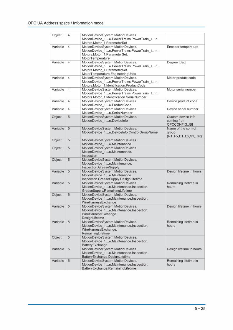
OPC UA Address space / Information model
Object 4 MotionDeviceSystem.MotionDevices. MotionDevice_1…n.PowerTrains.PowerTrain_1…n. Motors.Motor_1.ParameterSet
Variable 4 MotionDeviceSystem.MotionDevices. MotionDevice_1…n.PowerTrains.PowerTrain_1…n. Motors.Motor_1.ParameterSet. MotorTemperature
Encoder temperature
Variable 4 MotionDeviceSystem.MotionDevices. MotionDevice_1…n.PowerTrains.PowerTrain_1…n. Motors.Motor_1.ParameterSet. MotorTemperature.EngineeringUnits
Degree [deg]
Variable 4 MotionDeviceSystem.MotionDevices. MotionDevice_1…n.PowerTrains.PowerTrain_1…n. Motors.Motor_1.Identification.ProductCode
Motor product code
Variable 4 MotionDeviceSystem.MotionDevices. MotionDevice_1…n.PowerTrains.PowerTrain_1…n. Motors.Motor_1.Identification.SerialNumber
Motor serial number
Variable 4 MotionDeviceSystem.MotionDevices. MotionDevice_1…n.ProductCode
Device product code
Variable 4 MotionDeviceSystem.MotionDevices. MotionDevice_1…n.SerialNumber
Device serial number
Object 5 MotionDeviceSystem.MotionDevices. MotionDevice_1…n.DeviceInfo
Custom device info coming from OPCCONFIG.JBI
Variable 5 MotionDeviceSystem.MotionDevices. MotionDevice_1…n.DeviceInfo.ControlGroupName
Name of the control group (R1..Rx,B1..Bx,S1,..Sx)
Object 5 MotionDeviceSystem.MotionDevices. MotionDevice_1…n.Maintenance
Object 5 MotionDeviceSystem.MotionDevices. MotionDevice_1…n.Maintenance. Inspection
Object 5 MotionDeviceSystem.MotionDevices. MotionDevice_1…n.Maintenance. Inspection.GreaseSupply
Variable 5 MotionDeviceSystem.MotionDevices. MotionDevice_1…n.Maintenance. Inspection.GreaseSupply.DesignLifetime
Design lifetime in hours
Variable 5 MotionDeviceSystem.MotionDevices. MotionDevice_1…n.Maintenance.Inspection. GreaseSupply.RemainingLifetime
Remaining lifetime in hours
Object 5 MotionDeviceSystem.MotionDevices. MotionDevice_1…n.Maintenance.Inspection. WireHarnessExchange
Variable 5 MotionDeviceSystem.MotionDevices. MotionDevice_1…n.Maintenance.Inspection. WireHarnessExchange. DesignLifetime
Design lifetime in hours
Variable 5 MotionDeviceSystem.MotionDevices. MotionDevice_1…n.Maintenance.Inspection. WireHarnessExchange. RemainingLifetime
Remaining lifetime in hours
Object 5 MotionDeviceSystem.MotionDevices. MotionDevice_1…n.Maintenance.Inspection. BatteryExchange
Variable 5 MotionDeviceSystem.MotionDevices. MotionDevice_1…n.Maintenance.Inspection. BatteryExchange.DesignLifetime
Design lifetime in hours
Variable 5 MotionDeviceSystem.MotionDevices. MotionDevice_1…n.Maintenance.Inspection. BatteryExchange.RemainingLifetime
Remaining lifetime in hours
5 - 25
OPC UA Address space / Information model
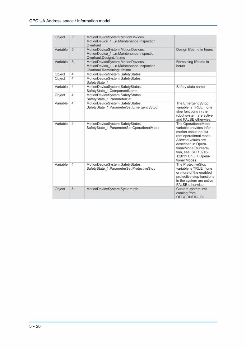
Object 5 MotionDeviceSystem.MotionDevices. MotionDevice_1…n.Maintenance.Inspection. Overhaul
Variable 5 MotionDeviceSystem.MotionDevices. MotionDevice_1…n.Maintenance.Inspection. Overhaul.DesignLifetime
Design lifetime in hours
Variable 5 MotionDeviceSystem.MotionDevices. MotionDevice_1…n.Maintenance.Inspection. Overhaul.RemainingLifetime
Remaining lifetime in hours
Object 4 MotionDeviceSystem.SafetyStates Object 4 MotionDeviceSystem.SafetyStates.
SafetyState_1
Variable 4 MotionDeviceSystem.SafetyStates. SafetyState_1.ComponentName
Safety state name
Object 4 MotionDeviceSystem.SafetyStates. SafetyState_1.ParameterSet
Variable 4 MotionDeviceSystem.SafetyStates. SafetyState_1.ParameterSet.EmergencyStop
The EmergencyStop variable is TRUE if one stop functions in the robot system are active, and FALSE otherwise.
Variable 4 MotionDeviceSystem.SafetyStates. SafetyState_1.ParameterSet.OperationalMode
The OperationalMode variable provides infor-mation about the cur-rent operational mode. Allowed values are described in Opera-tionalModeEnumera-tion, see ISO 10218-1:2011 Ch.5.7 Opera-tional Modes.
Variable 4 MotionDeviceSystem.SafetyStates. SafetyState_1.ParameterSet.ProtectiveStop
The ProtectiveStop variable is TRUE if one or more of the enabled protective stop functions in the system are active, FALSE otherwise.
Object 5 MotionDeviceSystem.SystemInfo Custom system info coming from OPCCONFIG.JBI
5 - 26
Configuration file OPCCONFIG.JBI
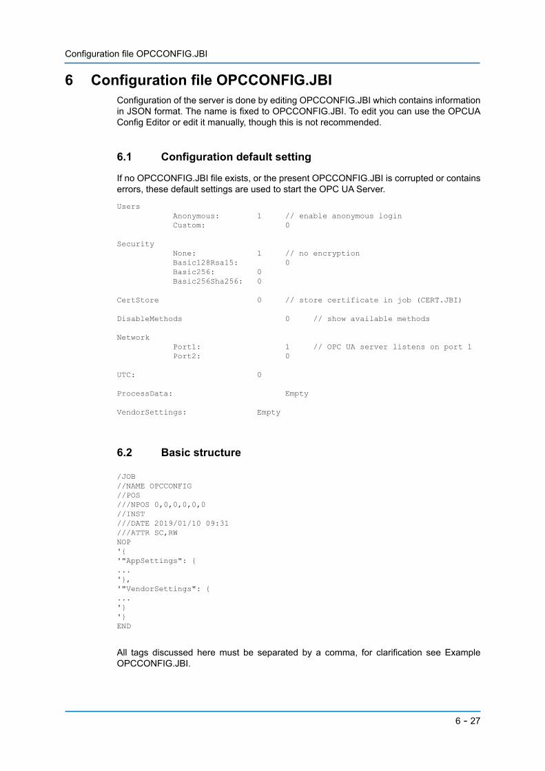
6 Configuration file OPCCONFIG.JBIConfiguration of the server is done by editing OPCCONFIG.JBI which contains informationin JSON format. The name is fixed to OPCCONFIG.JBI. To edit you can use the OPCUAConfig Editor or edit it manually, though this is not recommended.
6.1 Configuration default setting
If no OPCCONFIG.JBI file exists, or the present OPCCONFIG.JBI is corrupted or containserrors, these default settings are used to start the OPC UA Server.
6.2 Basic structure
All tags discussed here must be separated by a comma, for clarification see ExampleOPCCONFIG.JBI.
Users Anonymous: 1 // enable anonymous login Custom: 0 Security None: 1 // no encryption Basic128Rsa15: 0 Basic256: 0 Basic256Sha256: 0
CertStore 0 // store certificate in job (CERT.JBI)
DisableMethods 0 // show available methods
Network Port1: 1 // OPC UA server listens on port 1 Port2: 0 UTC: 0
ProcessData: Empty
VendorSettings: Empty
/JOB//NAME OPCCONFIG//POS///NPOS 0,0,0,0,0,0//INST///DATE 2019/01/10 09:31///ATTR SC,RWNOP'{'"AppSettings": {...'},'"VendorSettings": {...'}'}END
6 - 27
Configuration file OPCCONFIG.JBI
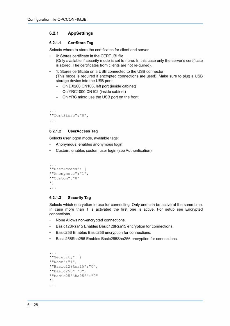
6.2.1 AppSettings
6.2.1.1 CertStore Tag
Selects where to store the certificates for client and server• 0: Stores certificate in the CERT.JBI file
(Only available if security mode is set to none. In this case only the server’s certificateis stored. The certificates from clients are not re-quired).
• 1: Stores certificate on a USB connected to the USB connector(This mode is required if encrypted connections are used). Make sure to plug a USBstorage device into the USB port:– On DX200 CN106, left port (inside cabinet)– On YRC1000 CN102 (inside cabinet)– On YRC micro use the USB port on the front
6.2.1.2 UserAccess Tag
Selects user logon mode, available tags:• Anonymous: enables anonymous login.• Custom: enables custom user login (see Authentication).
6.2.1.3 Security Tag
Selects which encryption to use for connecting. Only one can be active at the same time.In case more than 1 is activated the first one is active. For setup see Encryptedconnections.• None Allows non-encrypted connections.• Basic128Rsa15 Enables Basic128Rsa15 encryption for connections.• Basic256 Enables Basic256 encryption for connections.• Basic256Sha256 Enables Basic265Sha256 encryption for connections.
...'"CertStore":"0",...
...'"UserAccess": {'"Anonymous":"1",'"Custom":"0"'}...
...'"Security": {'"None":"1",'"Basic128Rsa15":"0",'"Basic256":"0",'"Basic256Sha256":"0"'}...
6 - 28
Configuration file OPCCONFIG.JBI
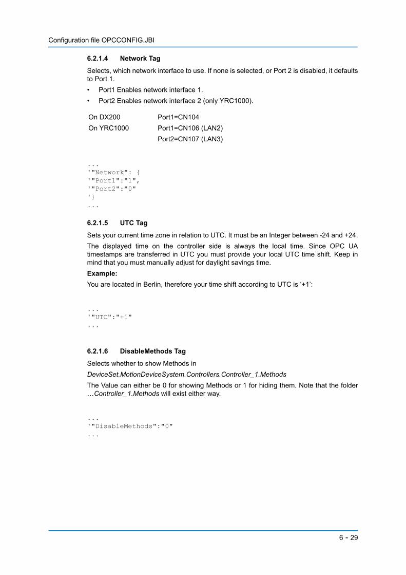
6.2.1.4 Network Tag
Selects, which network interface to use. If none is selected, or Port 2 is disabled, it defaultsto Port 1.• Port1 Enables network interface 1.• Port2 Enables network interface 2 (only YRC1000).
6.2.1.5 UTC Tag
Sets your current time zone in relation to UTC. It must be an Integer between -24 and +24.The displayed time on the controller side is always the local time. Since OPC UAtimestamps are transferred in UTC you must provide your local UTC time shift. Keep inmind that you must manually adjust for daylight savings time.Example:You are located in Berlin, therefore your time shift according to UTC is ‘+1’:
6.2.1.6 DisableMethods Tag
Selects whether to show Methods inDeviceSet.MotionDeviceSystem.Controllers.Controller_1.MethodsThe Value can either be 0 for showing Methods or 1 for hiding them. Note that the folder…Controller_1.Methods will exist either way.
On DX200 Port1=CN104On YRC1000 Port1=CN106 (LAN2)
Port2=CN107 (LAN3)
...'"Network": {'"Port1":"1",'"Port2":"0"'}...
...'"UTC":"+1"...
...'"DisableMethods":"0"...
6 - 29

Configuration file OPCCONFIG.JBI
6.2.1.7 ProcessData Tag
Configures the robot variables and IOs which should be added to the “ProcessData” nodeof the controller. Variables can have read or write access.Note that the available range of variables depends on your controller configuration:• B000 ..xxx Variable(s) of type Byte• I000 ..xxx Variable(s) of type Integer• D000 ..xxx Variable(s) of type Double• R000 ..xxx Variable(s) of type Real• M000 ..xxx Register(s)• S000 ..xxx Variable(s) of type StringFor IOs use the IO numbers as on the robot side. This makes it possible to add the completeaddress space from 00010 to 87017.Please note that only General Purpose Outputs and Network Inputs allow read/writeaccess. All others are read-only.• 00010 General Purpose Input 1• 10010 General Purpose Output1By using the name tag a custom name can be assigned to the variable. This name as wellas the name of the ProcessData Group cannot exceed 31 characters. If no name tag isspecified the variable/IO name is used.To import a group of variables/IOs at once replace the last digit by ‘x’.• 0001x Imports General Input Group 1 (00010.. 00017)• B00x Imports B000 to B009
Examples
Import User variables B001, R001 and R002 with a custom name and B002 with its default name. All variables are writeable.
...'"Variables":{'"B001" :{'"Name": "PartCounter",'"Rights": [{'"Access": "w"}]},'"B002" :{'"Rights": [{'"Access": "w"}]},'"R001" :{'"Name": "PartLocationX",'"Rights": [{'"Access": "w"}]},'"R002" : {'"Name": "PartLocationY",'"Rights": [{'"Access": "w"}]}'}...
6 - 30
Configuration file OPCCONFIG.JBI
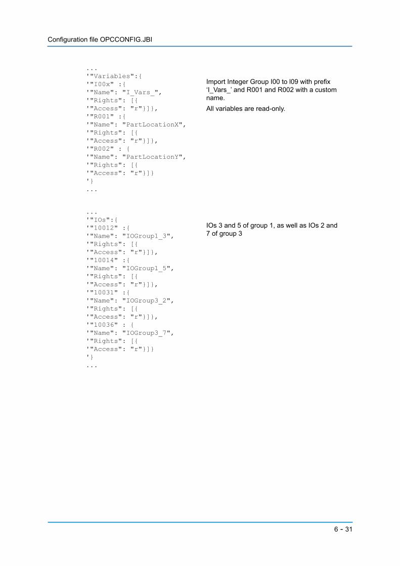
Import Integer Group I00 to l09 with prefix ‘I_Vars_’ and R001 and R002 with a custom name.All variables are read-only.
IOs 3 and 5 of group 1, as well as IOs 2 and 7 of group 3
...'"Variables":{'"I00x" :{'"Name": "I_Vars_",'"Rights": [{'"Access": "r"}]},'"R001" :{'"Name": "PartLocationX",'"Rights": [{'"Access": "r"}]},'"R002" : {'"Name": "PartLocationY",'"Rights": [{'"Access": "r"}]}'}...
...'"IOs":{'"10012" :{'"Name": "IOGroup1_3",'"Rights": [{'"Access": "r"}]},'"10014" :{'"Name": "IOGroup1_5",'"Rights": [{'"Access": "r"}]},'"10031" :{'"Name": "IOGroup3_2",'"Rights": [{'"Access": "r"}]},'"10036" : {'"Name": "IOGroup3_7",'"Rights": [{'"Access": "r"}]}'}...
6 - 31

Configuration file OPCCONFIG.JBI
The folder should be called ‘System’ and the IOs named after the following list:<50070 >RUN (Start Lamp)<50071>HOLD (Hold Lamp)<50073>Servo On<50074>I/O Simulated<50075>Job Edit Inform<50076>Jog Opn Inform<50077>OT Release
...'"System": {'"50070" : {'"Name":"RUN (Start Lamp)",'"Rights": [{'"Access": "r"}]},'"50071" : {'"Name":"HOLD (Hold Lamp)",'"Rights": [{'"Access": "r"}]},'"50073" : {'"Name":"Servo On",'"Rights": [{'"Access": "r"}]},'"50074" : {'"Name":"I/O Simulated",'"Rights": [{'"Access": "r"}]},'"50075" : {'"Name":"Job Edit Inform",'"Rights": [{'"Access": "r"}]},'"50076" : {'"Name":"Jog Opn Inform",'"Rights": [{'"Access": "r"}]},'"50077" : {'"Name":"OT Release",'"Rights": [{'"Access": "r"}]}'}...
6 - 32
Configuration file OPCCONFIG.JBI
6.2.2 VendorSettings
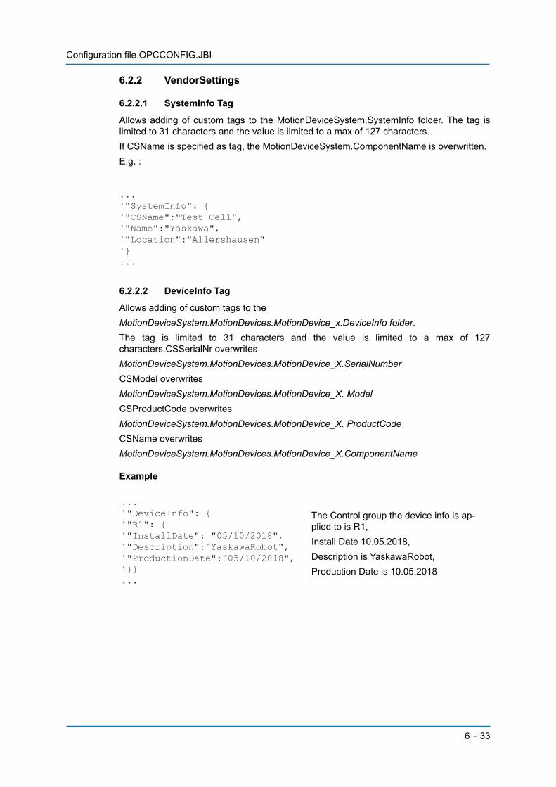
6.2.2.1 SystemInfo Tag
Allows adding of custom tags to the MotionDeviceSystem.SystemInfo folder. The tag islimited to 31 characters and the value is limited to a max of 127 characters.If CSName is specified as tag, the MotionDeviceSystem.ComponentName is overwritten.E.g. :
6.2.2.2 DeviceInfo Tag
Allows adding of custom tags to theMotionDeviceSystem.MotionDevices.MotionDevice_x.DeviceInfo folder. The tag is limited to 31 characters and the value is limited to a max of 127characters.CSSerialNr overwritesMotionDeviceSystem.MotionDevices.MotionDevice_X.SerialNumberCSModel overwritesMotionDeviceSystem.MotionDevices.MotionDevice_X. ModelCSProductCode overwritesMotionDeviceSystem.MotionDevices.MotionDevice_X. ProductCodeCSName overwritesMotionDeviceSystem.MotionDevices.MotionDevice_X.ComponentName
Example
The Control group the device info is ap-plied to is R1,Install Date 10.05.2018,Description is YaskawaRobot,Production Date is 10.05.2018
...'"SystemInfo": {'"CSName":"Test Cell",'"Name":"Yaskawa",'"Location":"Allershausen"'}...
...'"DeviceInfo": {'"R1": {'"InstallDate": "05/10/2018",'"Description":"YaskawaRobot",'"ProductionDate":"05/10/2018",'}}...
6 - 33
Configuration file OPCCONFIG.JBI
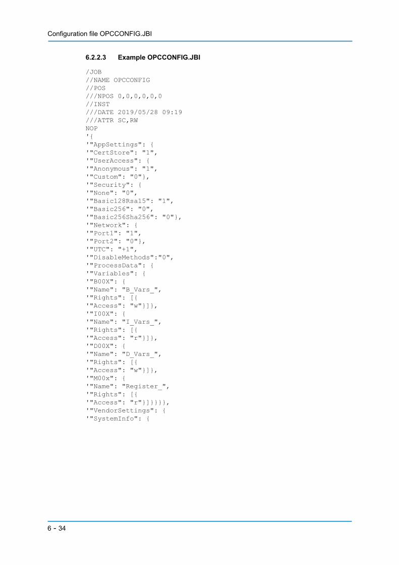
6.2.2.3 Example OPCCONFIG.JBI
/JOB//NAME OPCCONFIG//POS///NPOS 0,0,0,0,0,0//INST///DATE 2019/05/28 09:19///ATTR SC,RWNOP'{'"AppSettings": {'"CertStore": "1",'"UserAccess": {'"Anonymous": "1",'"Custom": "0"},'"Security": {'"None": "0",'"Basic128Rsa15": "1",'"Basic256": "0",'"Basic256Sha256": "0"},'"Network": {'"Port1": "1",'"Port2": "0"},'"UTC": "+1",'"DisableMethods":"0",'"ProcessData": {'"Variables": {'"B00X": {'"Name": "B_Vars_",'"Rights": [{'"Access": "w"}]},'"I00X": {'"Name": "I_Vars_",'"Rights": [{'"Access": "r"}]},'"D00X": {'"Name": "D_Vars_",'"Rights": [{'"Access": "w"}]},'"M00x": {'"Name": "Register_",'"Rights": [{'"Access": "r"}]}}}},'"VendorSettings": {'"SystemInfo": {
6 - 34

Configuration file OPCCONFIG.JBI
'"Name": "Yaskawa",'"Location": "Allershausen",'"CSName": "Test Cell"},'"DeviceInfo": {'"R1": {'"SerialNr": "34343355",'"OrderNr": "234246634",'"InstallDate": "10.05.2018",'"CSPowerTrain1": {'"CSMotor1": {'"CSSerialNr": "K18365-371-1",'"CSModel": "ERAS-1000-06VXH-3"}'}},'"R2": {'"SerialNr": "45454466",'"OrderNr": "234246634",'"InstallDate": "10.05.2018"}'}}}END
6 - 35

Configuration file OPCCONFIG.JBI
6.3 Introduction to the OPCUA Config Editor
The OPCUA Config Editor is a standalone PC application. It simplifies the generation of aconfiguration file for the OPC UA server. For any changes made in the app to take effectsave the config and upload it to the controller.Please register to our download portal (http://www.yaskawa.eu.com/en/service/robotics-software-download/) to get the latest version (Only if purchased through YASKAWAEurope).
6.3.1 Requirements
.Net 4.5 Framework.
6.3.2 App settings
ConfigTimestamp:Timestamp of last edit. Automatically updated when config is saved.Security:The used encryption method of the OPC UA serverNetwork:The network interfaceOn DX200 Port1=CN104On YRC1000 Port1=CN106 (LAN2). Port2=CN107 (LAN3).On YRC1000 micro ethernet port on the frontUTC:UTC Offset of the controller time(see UTC Tag)Certificate Storage:Location where the certificates are stored on the controller(see CertStore Tag)DisableMethods:Displays or hides the methods in …Controllers.Controller_1.Methods
6 - 36

Configuration file OPCCONFIG.JBI
6.3.3 Editing ProcessData
By clicking „New…“ a dialog box is opened, where a group name for a new set of processdata can be entered. Once a group is created it can be renamed by clicking “Rename…” ordeleted.
To add I010 to I019 select the ‘I’ checkbox, type ‘1x’ and click add. By selecting aProcessData item from the list the values can be modified or deleted. The naming of theIOs is the same as displayed on the teach pendant 10010….87017.
If a ProcessData group is selected from the drop-down menu, a vari-able or IO can be added by select-ing the corresponding checkbox and typing a number into the text-box. By typing ‘x’ for the last digit, a group of variables can be im-ported.
On OPC Server side the groups and variables are displayed in the ProcessData node of the Controller.MotionDeviceSystem.Controllers.Controller_1.ProcessData
6 - 37
Configuration file OPCCONFIG.JBI
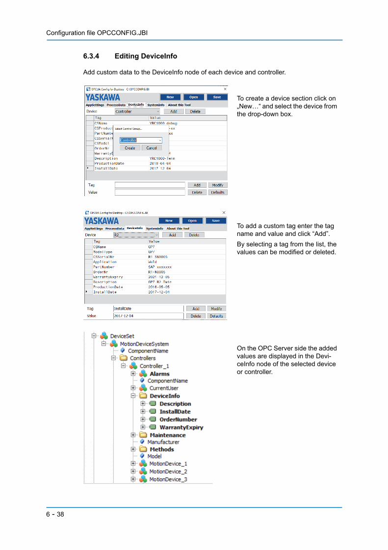
6.3.4 Editing DeviceInfo
Add custom data to the DeviceInfo node of each device and controller.
To create a device section click on „New…“ and select the device from the drop-down box.
To add a custom tag enter the tag name and value and click “Add”.By selecting a tag from the list, the values can be modified or deleted.
On the OPC Server side the added values are displayed in the Devi-ceInfo node of the selected device or controller.
6 - 38
Configuration file OPCCONFIG.JBI
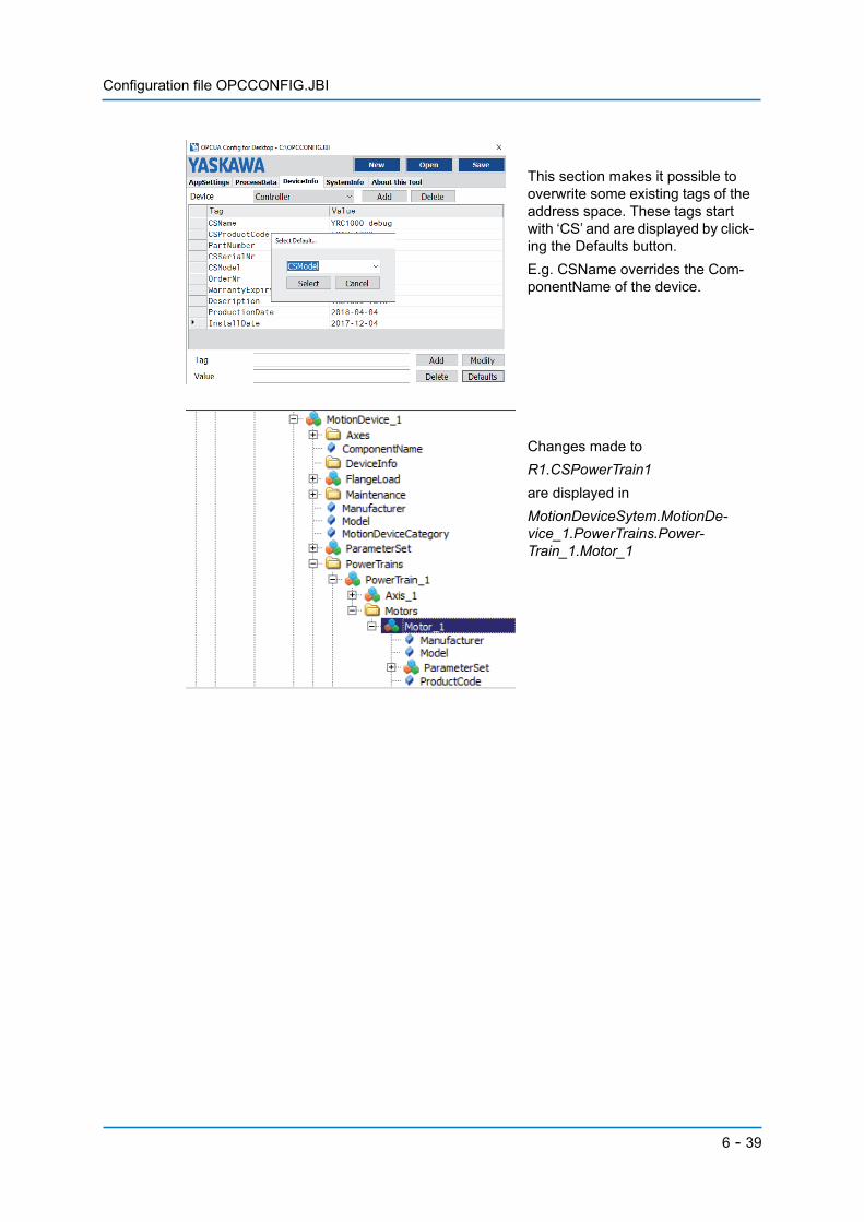
This section makes it possible to overwrite some existing tags of the address space. These tags start with ‘CS’ and are displayed by click-ing the Defaults button.E.g. CSName overrides the Com-ponentName of the device.
Changes made toR1.CSPowerTrain1are displayed inMotionDeviceSytem.MotionDe-vice_1.PowerTrains.Power-Train_1.Motor_1
6 - 39

Configuration file OPCCONFIG.JBI
6.3.5 Editing SystemInfo
Add custom data to the SystemInfo node of the MotionDeviceSystem.
To add a custom tag enter the tag name and value and click “Add”.By selecting a tag from the list the values can be modified or deleted.
All changes in the tab SystemInfo will be visible inMotionDeviceSystem.SystemInfoIf tag CSName is defined, it will over-writeMotionDeviceSytem.Component-Name.
6 - 40
Configuration file OPCCONFIG.JBI
6.4 Information for manual editing
To edit the OPCCONFIG.JBI file manually, follow these steps:• If you already have an OPCCONFIG.JBI, export it from the controller to a USB drive• Edit the OPCCONFIG.JBI according to this manual• Save the OPCCONFIG.JBI to any USB drive• Plug the USB drive into the pendant of the controller• Import OPCCONFIG.JBI as you would with any other job file• For the changes to take effect reboot the controller
Note that JBI files must comply with the following:• Each line cannot exceed 33 characters• A line must contain some characters• All lines between “NOP” and “END” must begin with an apostrophe• May not contain any vowels with diacritics (e.g. “ü”).
Please note:There is no guarantee your config will be loaded correctly by the server or OPCUA ConfigEditor, if edited manually.
6 - 41
Secured connections
7 Secured connectionsIf an endpoint with encryption is being used, additional setup is required to establish aconnection.
7.1 Encrypted connections
7.1.1 Preparing certificates
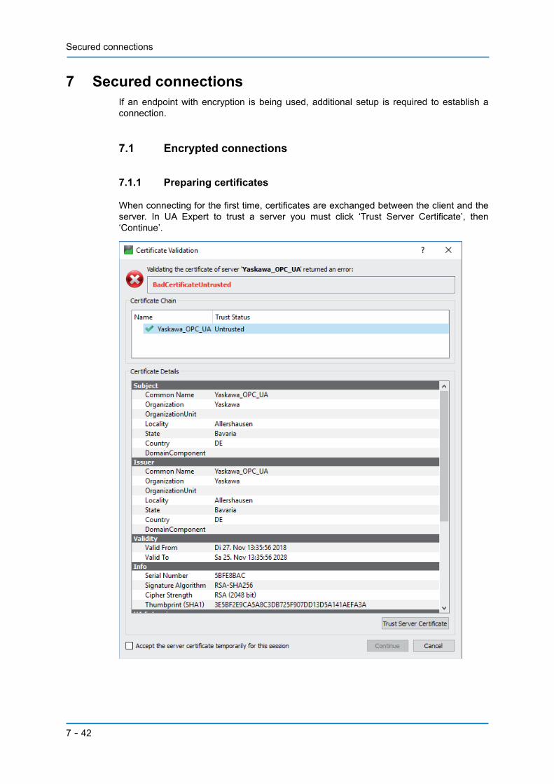
When connecting for the first time, certificates are exchanged between the client and theserver. In UA Expert to trust a server you must click ‘Trust Server Certificate’, then‘Continue’.
7 - 42

Secured connections
After the first connection from the client side, the client’s certificate is automatically storedin the rejected certificates path. To grant the client access to the server the certificate mustbe manually moved to the trusted location. Please follow the steps below.1. Power on the controller.2. Connect to the server in UA Expert. Your attempt will not succeed. This is normal.
3. Shutdown controller.4. Remove USB drive and move the client’s certificate from /pki/rejected/
to /pki/trusted/certs/
5. Plug the USB drive back into the controller and restart.6. Try connecting again. Now you should be able to log in to the server.
7 - 43

Secured connections
7.2 Authentication
7.2.1 Files to add user settings
In order to specify custom usernames and passwords, two additional files need to be editedin the root directory of the USB drive: group and passwd. To do so:• Make sure the controller is turned off.• Remove the USB drive from controller.• Plug the USB drive into the computer.• Right click the file you want to edit>Open.• Select Editor and edit the file according to this manual.• When finished click File>Save.• Plug the USB drive back into controller and start.
7.2.1.1 group
Defines groups and which users are part of this group according to the scheme:<GroupID> <GroupName> <all UserNames belonging to the Group separated bycommas>
NOTICEDouble-check for unnecessary white spaces; UserNames are only separated by a comma,if a UserName contains a white space use quotation marks.
GroupID is numbered consecutively, starting with 0, GroupName and UserNames arearbitrary.Example:User root is part of group root, users John and Jane are part of operators, Ron Roe is inusers:0 root root1 operators John,Jane2 users "Ron Roe
7.2.1.2 passwd
Defines passwords for the users mentioned in the group file according to the scheme:<UserID> <GroupID> <UserName> <Password encrypted in SHA1 >UserID is numbered consecutively, starting with 1, UserName has to match one UserNamefrom group file, if it contains a white space use quotation marks. To obtain the SHA1 encryptof a password use any online tool, for this example all passwords are “secret”, except forRon Roe, which is “terces”.Example:1 0 root e5e9fa1ba31ecd1ae84f75caaa474f3a663f05f42 1 John e5e9fa1ba31ecd1ae84f75caaa474f3a663f05f43 1 Jane e5e9fa1ba31ecd1ae84f75caaa474f3a663f05f44 2 "Ron Roe" 4db00e8b8e3445bb6c0bc7bdd4ca5608c20b563b
7 - 44
Appendix
8 Appendix
8.1 Third party licenses
8.1.1 OPC UA Server
LICENSE STATEMENTThis software includes the following third party software licensed under the MIT licensecJSONCopyright (c) 2009-2017 Dave Gamble and cJSON contributors Permission is herebygranted, free of charge, to any person obtaining a copy of this software and associateddocumentation files (the "Software"), to deal in the Software without restriction, includingwithout limitation the rights to use, copy, modify, merge, publish, distribute, sublicense, and/or sell copies of the Software, and to permit persons to whom the Software is furnished todo so, subject to the following conditions:The above copyright notice and this permission notice shall be included in all copies orsubstantial portions of the Software.THE SOFTWARE IS PROVIDED "AS IS", WITHOUT WARRANTY OF ANY KIND,EXPRESS OR IMPLIED, INCLUDING BUT NOT LIMITED TO THE WARRANTIES OFMERCHANTABILITY, FITNESS FOR A PARTICULAR PURPOSE ANDNONINFRINGEMENT. IN NO EVENT SHALL THE AUTHORS OR COPYRIGHTHOLDERS BE LIABLE FOR ANY CLAIM, DAMAGES OR OTHER LIABILITY, WHETHERIN AN ACTION OF CONTRACT, TORT OR OTHERWISE, ARISING FROM, OUT OF ORIN CONNECTION WITH THE SOFTWARE OR THE USE OR OTHER DEALINGS IN THESOFTWARE.
8.1.2 OPCUA Config Editor
LICENSE STATEMENTThis software includes the following third party software licensed under the MIT licenseJson.NETCopyright (c) 2007 James Newton-KingPermission is hereby granted, free of charge, to any person obtaining a copy of thissoftware and associated documentation files (the "Software"), to deal in the Softwarewithout restriction, including without limitation the rights to use, copy, modify, merge,publish, distribute, sublicense, and/or sell copies of the Software, and to permit persons towhom the Software is furnished to do so, subject to the following conditions:The above copyright notice and this permission notice shall be included in all copies orsubstantial portions of the Software.THE SOFTWARE IS PROVIDED "AS IS", WITHOUT WARRANTY OF ANY KIND,EXPRESS OR IMPLIED, INCLUDING BUT NOT LIMITED TO THE WARRANTIES OFMERCHANTABILITY, FIT-NESS FOR A PARTICULAR PURPOSE ANDNONINFRINGEMENT. IN NO EVENT SHALL THE AUTHORS OR COPYRIGHTHOLDERS BE LIABLE FOR ANY CLAIM, DAMAGES OR OTHER LIA-BILITY, WHETHERIN AN ACTION OF CONTRACT, TORT OR OTHERWISE, ARISING FROM, OUT OF ORIN CONNECTION WITH THE SOFTWARE OR THE USE OR OTHER DEALINGS IN THESOFTWARE.
8 - 45

Imprint
9 ImprintYaskawa Europe GmbHYaskawastraße 185391 AllershausenGermanyPhone 00498166900Fax 0049816690103
9 - 46

Imprint
9 - 47