Installation Manual -...
282
Model No. KX-TDA100 KX-TDA200 Hybrid IP-PBX Installation Manual Thank you for purchasing a Panasonic Hybrid IP-PBX. Please read this manual carefully before using this product and save this manual for future use. KX-TDA100/KX-TDA200: PMPR Software File Version 5.0000 or later SD Logo is a trademark.
Transcript of Installation Manual -...

Model No. KX-TDA100KX-TDA200
Hybrid IP-PBX
Installation Manual
Thank you for purchasing a Panasonic Hybrid IP-PBX.
Please read this manual carefully before using this product and save this manual for future use.
KX-TDA100/KX-TDA200: PMPR Software File Version 5.0000 or laterSD Logo is
a trademark.
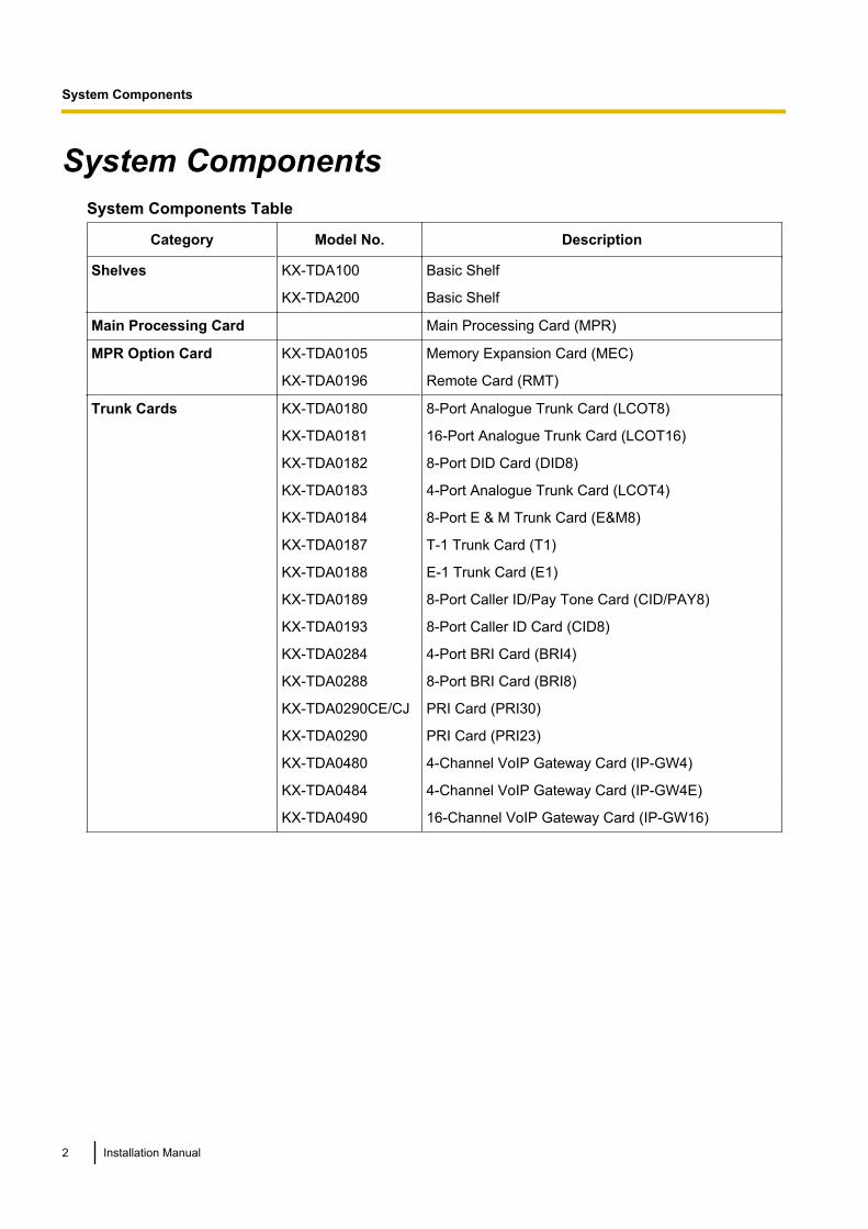
System ComponentsSystem Components Table
Category Model No. Description
Shelves KX-TDA100 Basic Shelf
KX-TDA200 Basic Shelf
Main Processing Card Main Processing Card (MPR)
MPR Option Card KX-TDA0105 Memory Expansion Card (MEC)
KX-TDA0196 Remote Card (RMT)
Trunk Cards KX-TDA0180 8-Port Analogue Trunk Card (LCOT8)
KX-TDA0181 16-Port Analogue Trunk Card (LCOT16)
KX-TDA0182 8-Port DID Card (DID8)
KX-TDA0183 4-Port Analogue Trunk Card (LCOT4)
KX-TDA0184 8-Port E & M Trunk Card (E&M8)
KX-TDA0187 T-1 Trunk Card (T1)
KX-TDA0188 E-1 Trunk Card (E1)
KX-TDA0189 8-Port Caller ID/Pay Tone Card (CID/PAY8)
KX-TDA0193 8-Port Caller ID Card (CID8)
KX-TDA0284 4-Port BRI Card (BRI4)
KX-TDA0288 8-Port BRI Card (BRI8)
KX-TDA0290CE/CJ PRI Card (PRI30)
KX-TDA0290 PRI Card (PRI23)
KX-TDA0480 4-Channel VoIP Gateway Card (IP-GW4)
KX-TDA0484 4-Channel VoIP Gateway Card (IP-GW4E)
KX-TDA0490 16-Channel VoIP Gateway Card (IP-GW16)
2 Installation Manual
System Components

Category Model No. Description
Extension Cards KX-TDA0143 4 Cell Station Interface Card (CSIF4)
KX-TDA0144 8 Cell Station Interface Card (CSIF8)
KX-TDA0170 8-Port Digital Hybrid Extension Card (DHLC8)
KX-TDA0171 8-Port Digital Extension Card (DLC8)
KX-TDA0172 16-Port Digital Extension Card (DLC16)
KX-TDA0173 8-Port Single Line Telephone Extension Card (SLC8)
KX-TDA0174 16-Port Single Line Telephone Extension Card(SLC16)
KX-TDA0175 16-Port Single Line Telephone Extension with MessageLamp Card (MSLC16)
KX-TDA0177 16-Port Single Line Telephone Extension Card withCaller ID (CSLC16)
KX-TDA0470 16-Channel VoIP Extension Card (IP-EXT16)
Other Cards KX-TDA0161 4-Port Doorphone Card (DPH4)
KX-TDA0162 2-Port Doorphone Card (German Type) (DPH2)
KX-TDA0164 4-Port External Input/Output Card (EIO4)
KX-TDA0166 16-Channel Echo Canceller Card (ECHO16)
KX-TDA0168 Extension Caller ID Card (EXT-CID)
KX-TDA0190 Optional 3-Slot Base Card (OPB3)
KX-TDA0191 4-Channel Message Card (MSG4)
KX-TDA0192 2-Channel Simplified Voice Message Card (ESVM2)
KX-TDA0194 4-Channel Simplified Voice Message Card (ESVM4)
KX-TDA0410 CTI Link Card (CTI-LINK)
Optional SD MemoryCards
KX-TDA0820 SD Memory Card for Software Upgrade
KX-TDA0920 SD Memory Card for Software Upgrade to EnhancedVersion
Power Supply Units(PSUs)
KX-TDA0103 L-Type Power Supply Unit (PSU-L)
KX-TDA0104 M-Type Power Supply Unit (PSU-M)
KX-TDA0108 S-Type Power Supply Unit (PSU-S)
Installation Manual 3
System Components
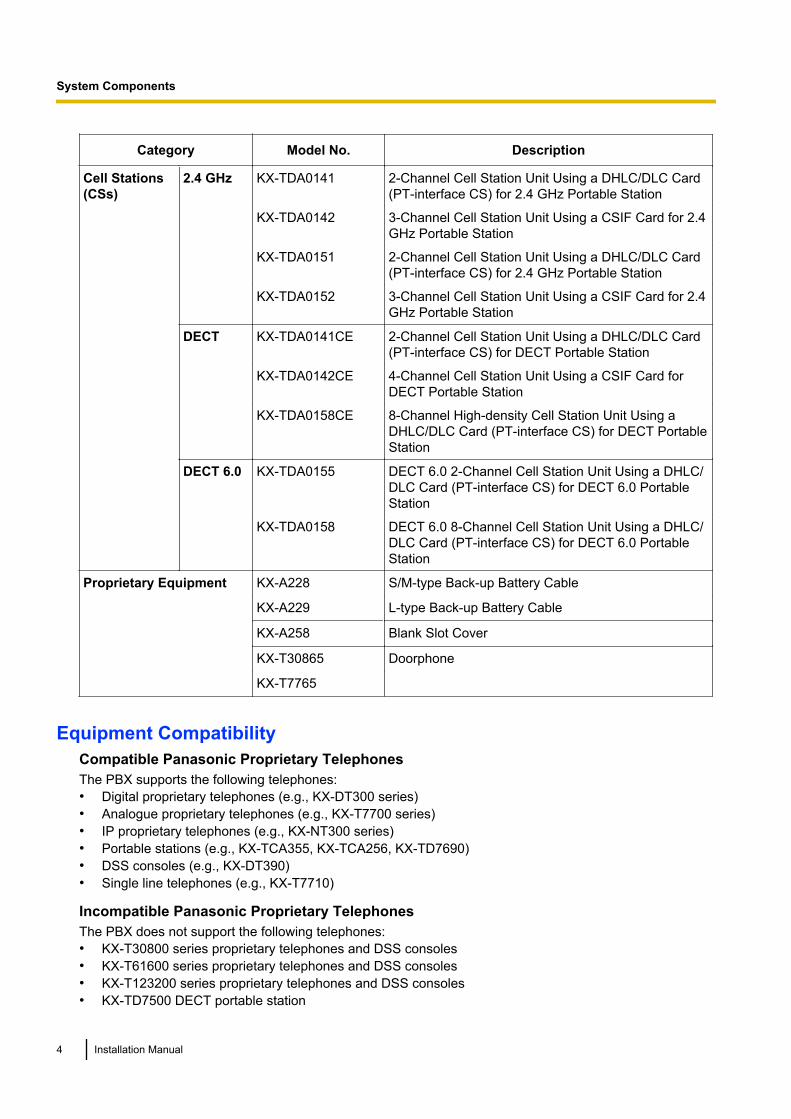
Category Model No. Description
Cell Stations(CSs)
2.4 GHz KX-TDA0141 2-Channel Cell Station Unit Using a DHLC/DLC Card(PT-interface CS) for 2.4 GHz Portable Station
KX-TDA0142 3-Channel Cell Station Unit Using a CSIF Card for 2.4GHz Portable Station
KX-TDA0151 2-Channel Cell Station Unit Using a DHLC/DLC Card(PT-interface CS) for 2.4 GHz Portable Station
KX-TDA0152 3-Channel Cell Station Unit Using a CSIF Card for 2.4GHz Portable Station
DECT KX-TDA0141CE 2-Channel Cell Station Unit Using a DHLC/DLC Card(PT-interface CS) for DECT Portable Station
KX-TDA0142CE 4-Channel Cell Station Unit Using a CSIF Card forDECT Portable Station
KX-TDA0158CE 8-Channel High-density Cell Station Unit Using aDHLC/DLC Card (PT-interface CS) for DECT PortableStation
DECT 6.0 KX-TDA0155 DECT 6.0 2-Channel Cell Station Unit Using a DHLC/DLC Card (PT-interface CS) for DECT 6.0 PortableStation
KX-TDA0158 DECT 6.0 8-Channel Cell Station Unit Using a DHLC/DLC Card (PT-interface CS) for DECT 6.0 PortableStation
Proprietary Equipment KX-A228 S/M-type Back-up Battery Cable
KX-A229 L-type Back-up Battery Cable
KX-A258 Blank Slot Cover
KX-T30865 Doorphone
KX-T7765
Equipment CompatibilityCompatible Panasonic Proprietary TelephonesThe PBX supports the following telephones:• Digital proprietary telephones (e.g., KX-DT300 series)• Analogue proprietary telephones (e.g., KX-T7700 series)• IP proprietary telephones (e.g., KX-NT300 series)• Portable stations (e.g., KX-TCA355, KX-TCA256, KX-TD7690)• DSS consoles (e.g., KX-DT390)• Single line telephones (e.g., KX-T7710)
Incompatible Panasonic Proprietary TelephonesThe PBX does not support the following telephones:• KX-T30800 series proprietary telephones and DSS consoles• KX-T61600 series proprietary telephones and DSS consoles• KX-T123200 series proprietary telephones and DSS consoles• KX-TD7500 DECT portable station
4 Installation Manual
System Components
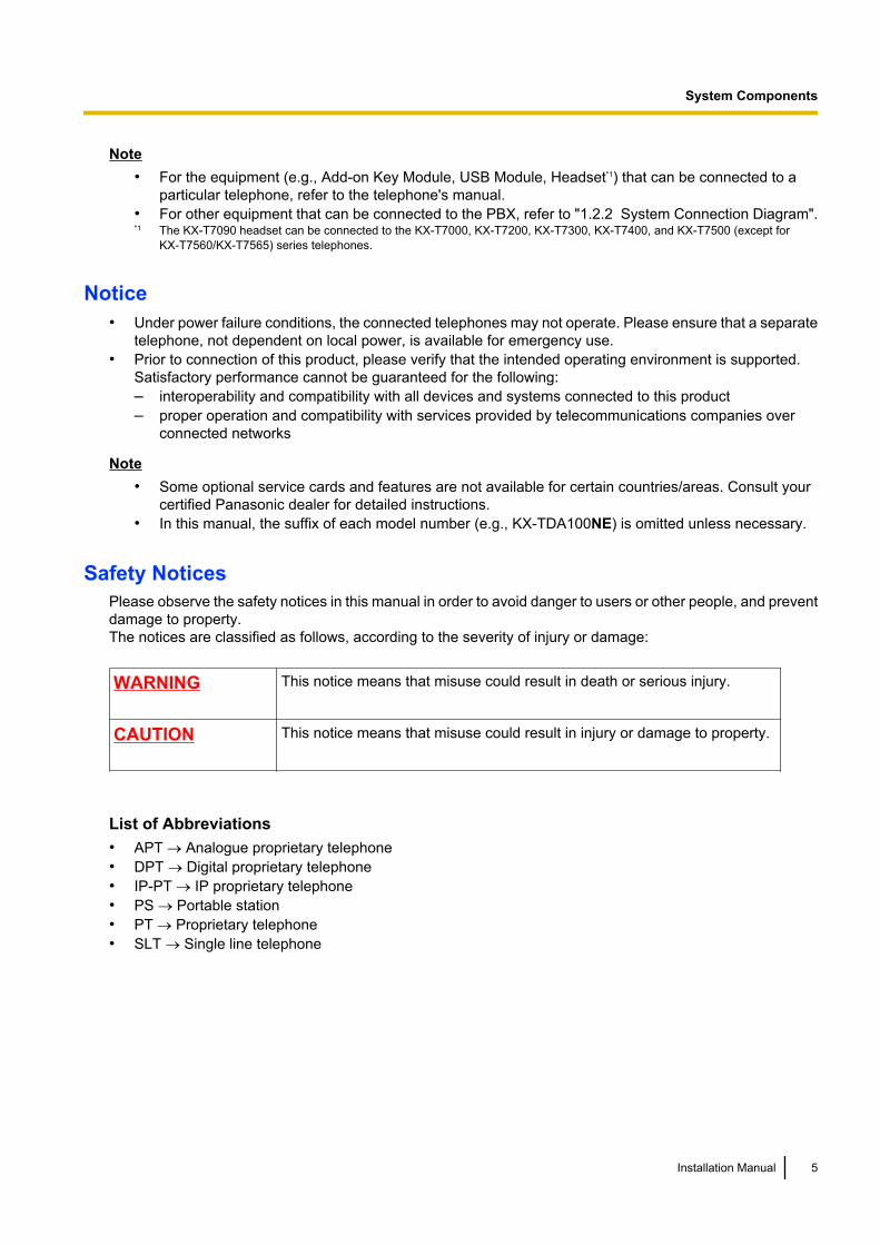
Note• For the equipment (e.g., Add-on Key Module, USB Module, Headset*1) that can be connected to a
particular telephone, refer to the telephone's manual.• For other equipment that can be connected to the PBX, refer to "1.2.2 System Connection Diagram".*1 The KX-T7090 headset can be connected to the KX-T7000, KX-T7200, KX-T7300, KX-T7400, and KX-T7500 (except for
KX-T7560/KX-T7565) series telephones.
Notice• Under power failure conditions, the connected telephones may not operate. Please ensure that a separate
telephone, not dependent on local power, is available for emergency use.• Prior to connection of this product, please verify that the intended operating environment is supported.
Satisfactory performance cannot be guaranteed for the following:– interoperability and compatibility with all devices and systems connected to this product– proper operation and compatibility with services provided by telecommunications companies over
connected networks
Note• Some optional service cards and features are not available for certain countries/areas. Consult your
certified Panasonic dealer for detailed instructions.• In this manual, the suffix of each model number (e.g., KX-TDA100NE) is omitted unless necessary.
Safety NoticesPlease observe the safety notices in this manual in order to avoid danger to users or other people, and preventdamage to property.The notices are classified as follows, according to the severity of injury or damage:
WARNING This notice means that misuse could result in death or serious injury.
CAUTION This notice means that misuse could result in injury or damage to property.
List of Abbreviations• APT ® Analogue proprietary telephone• DPT ® Digital proprietary telephone• IP-PT ® IP proprietary telephone• PS ® Portable station• PT ® Proprietary telephone• SLT ® Single line telephone
Installation Manual 5
System Components

Important Safety InstructionsWhen using your telephone equipment, basic safety precautions should always be followed to reduce the riskof fire, electric shock and injury to persons, including the following:• Do not use the product near water, for example, near a bathtub, wash bowl, kitchen sink, or laundry tub,
in a wet basement, or near a swimming pool.• Avoid using wired telephones during an electrical storm. There is a remote risk of electric shock from
lightning.• Do not use a telephone in the vicinity of a gas leak to report the leak.
SAVE THESE INSTRUCTIONS
6 Installation Manual
Important Safety Instructions
Important InformationSAVE THESE INSTRUCTIONS
WARNING
SAFETY REQUIREMENTSFor All Telephone Equipment• Do not install the product in any other way than described in relevant manuals.• For safety reasons, do not physically modify the product or any optional equipment.• The product may only be installed and serviced by qualified service personnel.• To prevent possible fire or electric shock, do not expose the product to rain or moisture.• Follow all warnings and instructions marked on the product.• Do not place the product on an unstable surface, as a fall may cause serious internal damage.• The product should only be connected to the type of electrical power supply specified on the product label.
If you are not sure of the type of power supply to your home, consult your dealer or local power company.• For safety purposes some products are equipped with an earthed plug. If you do not have an earthed outlet,
please have one installed. Do not bypass this safety feature by tampering with the plug.• Do not allow anything to rest on the power cord. Do not locate the product where the power cord may be
stepped on or tripped on.• To reduce the risk of fire or electric shock, do not overload wall outlets and extension cords.• To reduce the risk of electric shock, do not disassemble the product. Only qualified personnel should
service the product. Opening or removing covers may expose you to dangerous voltages or other risks.Incorrect reassembly can cause electric shock.
• Unplug the product from the wall outlet and have it serviced by qualified service personnel in the followingcases:a. When the power supply cord or plug is damaged or frayed.b. If liquid has been spilled into the product.c. If the product has been exposed to rain or water.d. If the product does not operate according to the operating instructions. Adjust only the controls that are
explained in the operating instructions. Improper adjustment of other controls may result in damageand may require service by a qualified technician to restore the product to normal operation.
e. If the product has been dropped or the cabinet has been damaged.f. If product performance deteriorates.
For the PBX• If damage to the unit exposes any internal parts, disconnect the power supply cord immediately and return
the unit to your dealer.• Do not bundle cables that are connected to the PBX with the AC power cords of machines located
nearby.Use protectors to prevent the cables from being stepped on. Failure to do so may cause fire or electricshock.
• Unplug this unit from the AC outlet if it emits smoke, an abnormal smell or makes unusual noise. Theseconditions can cause fire or electric shock. Confirm that smoke has stopped and contact an authorisedPanasonic Factory Service Centre.
• Danger of explosion exists if a battery is incorrectly replaced. Replace only with the same or equivalenttype recommended by the battery manufacturer. Dispose of used batteries according to themanufacturer’s instructions.
• Only use the wall-mounting equipment (anchor plugs, screws, metal bracket) included with the PBX.
Installation Manual 7
Important Information
• When driving the screws into the wall, be careful to avoid touching any metal laths, wire laths or metalplates in the wall.
• When this product is no longer in use, make sure to detach it from the wall.• Do not insert objects of any kind into this product through its slots and openings, as they may touch
dangerous voltage points or short out parts that could result in a risk of fire or electric shock. Never spillliquid of any kind on or in the product.
CAUTION
SAFETY REQUIREMENTSFor All Telephone Equipment• Unplug the product from the wall outlet before cleaning. Wipe the product with a soft cloth. Do not clean
with abrasive powders or with chemical agents such as benzene or thinner. Do not use liquid cleaners oraerosol cleaners.
• The product should be kept free of dust, moisture, high temperature (more than 40 °C) and vibration, andshould not be exposed to direct sunlight.
For the PBX• When relocating the equipment, first disconnect the telecom connection before disconnecting the power
connection. When the unit is installed in the new location, reconnect the power first, and then reconnectthe telecom connection.
• The power supply cord is used as the main disconnect device. Ensure that the AC outlet is located nearthe equipment and is easily accessible.
• The SD Memory Card poses a choking hazard. Keep the SD Memory Card out of reach of children.• Slots and openings in the front, back and bottom of the cabinet are provided for ventilation; to protect it
from overheating, these openings must not be blocked or covered. The openings should never be blockedby placing the product on a bed, sofa, rug, or other similar surface while in use. The product should neverbe placed near or over a radiator or other heat source. This product should not be placed in a sealedenvironment unless proper ventilation is provided.
For the Cell Station2.4 GHz Cell Station (Except for KX-TDA0151CN)Medical—consult the manufacturer of any personal medical devices, such as pacemakers, to determine if theyare adequately shielded from external RF (radio frequency) energy. (The unit operates in the frequency rangeof 2401 MHz to 2480 MHz, and the power output level can range from 0.004 W to 0.4 W.) Do not use the unitin health care facilities if any regulations posted in the area instruct you not to do so. Hospitals or health carefacilities may be using equipment that could be sensitive to external RF (radio frequency) energy.
2.4 GHz Cell Station (Only for KX-TDA0151CN)Medical—consult the manufacturer of any personal medical devices, such as pacemakers, to determine if theyare adequately shielded from external RF (radio frequency) energy. (The unit operates in the frequency rangeof 2401 MHz to 2480 MHz, and the output peak power level is less than 0.16 W.) Do not use the unit in healthcare facilities if any regulations posted in the area instruct you not to do so. Hospitals or health care facilitiesmay be using equipment that could be sensitive to external RF (radio frequency) energy.
DECT Cell StationMedical—consult the manufacturer of any personal medical devices, such as pacemakers, to determine if theyare adequately shielded from external RF (radio frequency) energy. (The unit operates in the frequency rangeof 1881 MHz to 1898 MHz, and the output peak power level is less than 0.25 W.) Do not use the unit in health
8 Installation Manual
Important Information
care facilities if any regulations posted in the area instruct you not to do so. Hospitals or health care facilitiesmay be using equipment that could be sensitive to external RF (radio frequency) energy.
DECT 6.0 Cell StationMedical—consult the manufacturer of any personal medical devices, such as pacemakers, to determine if theyare adequately shielded from external RF (radio frequency) energy. (The unit operates in the frequency rangeof 1920 MHz to 1930 MHz, and the output peak power level is less than 0.12 W.) Do not use the unit in healthcare facilities if any regulations posted in the area instruct you not to do so. Hospitals or health care facilitiesmay be using equipment that could be sensitive to external RF (radio frequency) energy.
SECURITY REQUIREMENTSIn order to use the PBX safely and correctly, the Security Requirements below must be observed. Failure todo so may result in:• Loss, leakage, falsification or theft of user information.• Illegal use of the PBX by a third party.• Interference or suspension of service caused by a third party.
What is User Information?User Information is defined as:1. Information stored on the SD Memory Card
Phonebook data, user IDs, system settings data, passwords (User/Administrator/Installer), PersonalIdentification Numbers (PINs), etc.
2. Information sent from the PBX to a PC or other external device:Phone call data (including telephone numbers of outside parties), call charge data, etc.
Requirements1. The SD Memory Card contains software for all the processes of the PBX and all customer data. It can be
easily removed and taken away from the PBX by a third party. Therefore, do not allow unauthorised accessto prevent data leakage.
2. Always make backups of data stored on the SD Memory Card. For details, refer to "2.6.2 Utility—FileTransfer PC to PBX (SD Card)" and "2.6.3 Utility—File Transfer PBX (SD Card) to PC" in the PCProgramming Manual.
3. To prevent illegal access from the Internet, activate a Firewall.4. To avoid unauthorised access and possible abuse of the PBX, we strongly recommend:
a. Keeping the password secret.b. Selecting a complex, random password that cannot be easily guessed.c. Changing your password regularly.
5. Perform the following when sending the PBX for repair or handing it over to a third party.a. Make a backup of data stored on the SD Memory Card.b. Using an SD formatter, format the SD Memory Card so that information cannot be retrieved from it.
6. To prevent data leakage, render the SD Memory Card physically unusable before disposal.7. When user information is sent from the PBX to a PC or other external device, the confidentiality of that
information becomes the responsibility of the customer. Before disposing of the PC or other external device,ensure that data cannot be retrieved from it by formatting the hard disk and/or rendering it physicallyunusable.
Notice
SAFETY REQUIREMENTSFor All Telephone Equipment• Read and understand all instructions.
Installation Manual 9
Important Information
For the PBX• Keep the unit away from heating appliances and devices that generate electrical noise such as fluorescent
lamps, motors and televisions. These noise sources can interfere with the performance of the PBX.• If you are having problems making calls to outside destinations, follow this procedure to test the trunks:
a. Disconnect the PBX from all trunks.b. Connect known working SLTs to those trunks.c. Make a call to an external destination using those SLTs.If a call cannot be carried out correctly, there may be a problem with the trunk that the SLT is connectedto. Contact your telephone company.If all SLTs operate properly, there may be a problem with your PBX. Do not reconnect the PBX to the trunksuntil it has been serviced by an authorised Panasonic Factory Service Centre.
10 Installation Manual
Important Information
PrecautionFor users in the United KingdomFOR YOUR SAFETY, PLEASE READ THE FOLLOWING TEXT CAREFULLY.
This appliance is supplied with a moulded three-pin mains plug for your safety and convenience. A 5 amp fuseis fitted in this plug. Should the fuse need to be replaced, please ensure that the replacement fuse has a ratingof 5 amps and that it is approved by ASTA or BSI to BS1362.
Check for the ASTA mark or the BSI mark on the body of the fuse.
If the plug contains a removable fuse cover, you must ensure that it is refitted when the fuse is replaced. If youlose the fuse cover, the plug must not be used until a replacement cover is obtained. A replacement fuse covercan be purchased from your local Panasonic dealer.
IF THE FITTED MOULDED PLUG IS UNSUITABLE FOR THE AC OUTLET IN YOUR PREMISES, THEN THEFUSE SHOULD BE REMOVED AND THE PLUG CUT OFF AND DISPOSED OF SAFELY. THERE IS ADANGER OF SEVERE ELECTRICAL SHOCK IF THE CUT-OFF PLUG IS INSERTED INTO ANY 13 AMPSOCKET.
If a new plug is to be fitted, please observe the wiring code as shown below. If in any doubt, please consult aqualified electrician.
WARNINGThis appliance must be earthed.
IMPORTANTThe wires in the mains lead are coloured as follows:Green-and-yellow: EarthBlue: NeutralBrown: LiveAs the colours of the wires in the mains lead of this apparatus may not correspond with the colouredmarkings identifying the terminals in your plug, proceed as follows.The wire that is coloured GREEN-AND-YELLOW must be connected to the terminal in the plug that ismarked with the letter E or by the safety earth symbol or coloured GREEN or GREEN-AND-YELLOW.The wire that is coloured BLUE must be connected to the terminal that is marked with the letter N or colouredBLACK.The wire that is coloured BROWN must be connected to the terminal that is marked with the letter L orcoloured RED.
How to replace the fuse: Open the fuse compartment with a screwdriver and replace the fuse and fuse cover.
The equipment must be connected to direct extension lines, and a payphone should not be connected as anextension.
Installation Manual 11
Precaution
999 and 112 can be dialled on the apparatus after accessing the Exchange line for the purpose of makingoutgoing calls to the BT emergency services.
During dialling, this apparatus may tinkle the bells of other telephones using the same line. This is not a faultand we advise you not to call the Fault Repair Service.
For users in the European Union only
Information for Users on Collection and Disposal of Old Equipment and used Batteries
These symbols on the products, packaging, and/or accompanying documents mean thatused electrical and electronic products and batteries should not be mixed with generalhousehold waste.For proper treatment, recovery and recycling of old products and used batteries, please takethem to applicable collection points, in accordance with your national legislation and theDirectives 2002/96/EC and 2006/66/EC.By disposing of these products and batteries correctly, you will help to save valuableresources and prevent any potential negative effects on human health and the environmentwhich could otherwise arise from inappropriate waste handling.For more information about collection and recycling of old products and batteries, pleasecontact your local municipality, your waste disposal service or the point of sale where youpurchased the items.Penalties may be applicable for incorrect disposal of this waste, in accordance with nationallegislation.
For business users in the European UnionIf you wish to discard electrical and electronic equipment, please contact your dealer orsupplier for further information.
Information on Disposal in other Countries outside the European UnionThese symbols are only valid in the European Union. If you wish to discard these items,please contact your local authorities or dealer and ask for the correct method of disposal.
Note for the battery symbol (bottom two symbol examples):This symbol might be used in combination with a chemical symbol. In this case it complieswith the requirement set by the Directive for the chemical involved.
For users in Germany only• Machine Noise Information Ordinance, 3rd GPSGV: The highest sound pressure level is 70 dB (A) or less
according to EN ISO 7779.• This equipment is not for use at video display work stations according to BildscharbV.
For users in New Zealand only• This equipment shall not be set to make automatic calls to the Telecom ‘111’ Emergency Service.• The grant of a Telepermit for any item of terminal equipment indicates only that Telecom has accepted
that the item complies with minimum conditions for connection to its network. It indicates no endorsementof the product by Telecom, nor does it provide any sort of warranty. Above all, it provides no assurancethat any item will work correctly in all respects with another item of Telepermitted equipment of a differentmake or model, nor does it imply that any product is compatible with all of Telecom’s network services.
• This equipment is not capable, under all operating conditions, of correct operation at the higher speeds forwhich it is designed. Telecom will accept no responsibility should difficulties arise in such circumstances.
12 Installation Manual
Precaution
• Some parameters required for compliance with Telecom’s Telepermit requirements are dependent on theequipment (PBX) associated with this modem. In order to operate within the limits for compliance withTelecom’s Specifications, the associated PBX equipment shall be set to ensure that modem calls areanswered between 3 and 30 seconds of receipt of ringing.
• Using the toll services of a company other than Telecom:If the PBX is set up to use the toll services of a company other than Telecom, the telephone numbersdialled from the Caller Display listings within the PBX will be directed through the toll services of the othercompany because the telephone numbers include the toll access digit and area code digit. A toll chargemay be incurred. Please check with the toll carrier concerned.
• IMPORTANT NOTICEUnder power failure conditions, the connected telephones may not operate. Please ensure that a separatetelephone, not dependent on local power, is available for emergency use.
• APPLICABLE ONLY TO TELECOM CUSTOMERS WHO HAVE AUTOMATIC ACCESS TO OTHERCARRIERS FOR TOLL CALLSWhen calling back a number from the Caller ID list, all numbers prefixed with "0 + AREA CODE" will beautomatically forwarded to your toll carrier. This includes numbers in your local calling area. The zero +area code should either be removed when calling back local numbers, or check with your toll carrier thata charge will not be levied.
• All persons using this device for recording telephone conversations shall comply with New Zealand law.This requires that at least one party to the conversation is to be aware that it is being recorded. In addition,the principles enumerated in the Privacy Act 1993 shall be complied with in respect to the nature of thepersonal information collected, the purpose for its collection, how it is used, and what is disclosed to anyother party.
For users in Australia only• No External TRC Terminal is provided due to an Internal Link between PE and TRC.
For users in Taiwan only• Lithium batteries can be found in the circuit boards of the main board and optional cards of the PBX.
Note• When disposing of any of the above products, all batteries must be removed. Follow the applicable
laws, regulations, and guidelines in your country/area regarding disposal of batteries.• When replacing a battery, use only the same battery type, or an equivalent recommended by the battery
manufacturer.
NoticeRegarding removing or replacing a battery in the circuit board, consult your dealer.
Installation Manual 13
Precaution

IntroductionThis Installation Manual is designed to serve as an overall technical reference for the Panasonic Hybrid IP-PBX,KX-TDA100/KX-TDA200. It provides instructions for installing the hardware, and programming the PBX usingthe Maintenance Console.
The Structure of this ManualThis manual contains the following sections:Section 1 System OutlineProvides general information on the PBX, including the system capacity and specifications.Section 2 InstallationDescribes the procedures to install the PBX. Detailed instructions for planning the installation site, installingthe optional service cards, and cabling of peripheral equipment are provided. Further information on systemexpansion and peripheral equipment installation is included.Section 3 Guide for the Maintenance ConsoleExplains the installation procedure, structure, and basic information of the Maintenance Console.Section 4 TroubleshootingProvides information on the PBX and telephone troubleshooting.
About the Other ManualsAlong with this Installation Manual, the following manuals are available:Feature GuideDescribes all basic, optional and programmable features of the PBX.PC Programming ManualProvides step-by-step instructions for performing system programming using a PC.PT Programming ManualProvides step-by-step instructions for performing system programming using a PT.User ManualProvides operating instructions for end users using a PT, SLT, PS, or DSS Console.
About the software version of your PBXThe contents of this manual apply to PBXs with a certain software version, as indicated on the cover of thismanual. To confirm the software version of your PBX, see "How do I confirm the software version of the PBXor installed cards?" in 2.7.1 Frequently Asked Questions (FAQ) of the PC Programming Manual, or "[190]Main Processing (MPR) Software Version Reference" in the PT Programming Manual.
Trademarks• The Bluetooth® word mark and logos are owned by the Bluetooth SIG, Inc. and any use of such marks by
Panasonic Corporation is under licence.• Microsoft, Windows, and Windows Vista are either registered trademarks or trademarks of Microsoft
Corporation in the United States and/or other countries.• All other trademarks identified herein are the property of their respective owners.• Microsoft product screen shot(s) reprinted with permission from Microsoft Corporation.
14 Installation Manual
Introduction
Table of Contents1 System Outline .......................................................................................191.1 System Highlights ...........................................................................................................201.1.1 System Highlights ...........................................................................................................201.2 Basic System Construction ...........................................................................................221.2.1 Basic Shelf .....................................................................................................................221.2.2 System Connection Diagram ..........................................................................................231.3 Optional Equipment ........................................................................................................241.3.1 Optional Equipment ........................................................................................................251.4 Specifications ..................................................................................................................281.4.1 General Description ........................................................................................................281.4.2 Characteristics ................................................................................................................301.4.3 System Capacity ............................................................................................................31
2 Installation ..............................................................................................392.1 Before Installation ...........................................................................................................402.1.1 Before Installation ...........................................................................................................402.2 Installation of the PBX ....................................................................................................422.2.1 Unpacking ......................................................................................................................422.2.2 Names and Locations .....................................................................................................432.2.3 Opening/Closing the Front Cover ...................................................................................442.2.4 Installing/Replacing the Power Supply Unit ....................................................................462.2.5 Frame Earth Connection ................................................................................................502.2.6 Backup Battery Connection ............................................................................................512.2.7 Installing/Removing the Optional Service Cards ............................................................532.2.8 Types of Connectors ......................................................................................................582.2.9 Attaching a Ferrite Core .................................................................................................602.2.10 Fastening Amphenol Connector .....................................................................................632.2.11 Wall Mounting (KX-TDA200) ..........................................................................................652.2.12 Wall Mounting (KX-TDA100) ..........................................................................................672.2.13 Floor Standing (KX-TDA200 Only) .................................................................................692.2.14 Surge Protector Installation ............................................................................................712.3 Information about the Main Processing Card ..............................................................742.3.1 MPR Card .......................................................................................................................742.3.2 MEC Card (KX-TDA0105) ..............................................................................................762.3.3 RMT Card (KX-TDA0196) ..............................................................................................772.4 Information about the Trunk Cards ...............................................................................782.4.1 LCOT4 Card (KX-TDA0183), LCOT8 Card (KX-TDA0180), and LCOT16 Card
(KX-TDA0181) ................................................................................................................782.4.2 DID8 Card (KX-TDA0182) ..............................................................................................802.4.3 CID/PAY8 Card (KX-TDA0189) ......................................................................................822.4.4 CID8 Card (KX-TDA0193) ..............................................................................................832.4.5 E&M8 Card (KX-TDA0184) ............................................................................................842.4.6 T1 Card (KX-TDA0187) ..................................................................................................862.4.7 E1 Card (KX-TDA0188) ..................................................................................................892.4.8 BRI4 Card (KX-TDA0284) and BRI8 Card (KX-TDA0288) .............................................922.4.9 PRI30 Card (KX-TDA0290CE/KX-TDA0290CJ) ............................................................962.4.10 PRI23 Card (KX-TDA0290) ............................................................................................992.4.11 IP-GW4 Card (KX-TDA0480) .......................................................................................1022.4.12 IP-GW4E Card (KX-TDA0484) .....................................................................................1042.4.13 IP-GW16 Card (KX-TDA0490) .....................................................................................1062.5 Information about the Extension Cards ......................................................................1082.5.1 CSIF4 Card (KX-TDA0143) and CSIF8 Card (KX-TDA0144) ......................................108
Installation Manual 15
Table of Contents
2.5.2 DHLC8 Card (KX-TDA0170) ........................................................................................1102.5.3 DLC8 Card (KX-TDA0171) ...........................................................................................1122.5.4 DLC16 Card (KX-TDA0172) .........................................................................................1142.5.5 SLC8 Card (KX-TDA0173) ...........................................................................................1162.5.6 EXT-CID Card (KX-TDA0168) ......................................................................................1182.5.7 SLC16 Card (KX-TDA0174), MSLC16 Card (KX-TDA0175), and CSLC16 Card
(KX-TDA0177) ..............................................................................................................1192.5.8 IP-EXT16 Card (KX-TDA0470) ....................................................................................1222.6 Information about the Other Cards .............................................................................1242.6.1 OPB3 Card (KX-TDA0190) ..........................................................................................1242.6.2 DPH4 Card (KX-TDA0161) ..........................................................................................1252.6.3 DPH2 Card (KX-TDA0162) ..........................................................................................1272.6.4 EIO4 Card (KX-TDA0164) ............................................................................................1302.6.5 ECHO16 Card (KX-TDA0166) ......................................................................................1332.6.6 MSG4 Card (KX-TDA0191) ..........................................................................................1342.6.7 ESVM2 Card (KX-TDA0192) and ESVM4 Card (KX-TDA0194) ..................................1352.6.8 CTI-LINK Card (KX-TDA0410) .....................................................................................1362.7 Connection of Extensions ............................................................................................1382.7.1 Maximum Cabling Distances of the Extension Wiring (Twisted Cable) ........................1382.7.2 Parallel Connection of the Extensions ..........................................................................1402.7.3 Digital EXtra Device Port (Digital XDP) Connection .....................................................1432.7.4 First Party Call Control CTI Connection .......................................................................1502.8 Connection of DECT Portable Stations .......................................................................1512.8.1 Overview ......................................................................................................................1512.8.2 Procedure Overview .....................................................................................................1532.8.3 Site Planning ................................................................................................................1552.8.4 Before Site Survey .......................................................................................................1592.8.5 Site Survey Using the KX-TCA255/KX-TCA256/KX-TCA355/KX-TD7590 ..................1642.8.6 After Site Survey ..........................................................................................................1682.8.7 Connecting a Cell Station to the PBX ...........................................................................1692.8.8 Wall Mounting ...............................................................................................................1782.9 Connection of 2.4 GHz Portable Stations ...................................................................1822.9.1 Overview ......................................................................................................................1822.9.2 Procedure Overview .....................................................................................................1842.9.3 Site Planning ................................................................................................................1862.9.4 Before Site Survey .......................................................................................................1902.9.5 Site Survey ...................................................................................................................1932.9.6 After Site Survey ..........................................................................................................1972.9.7 Connecting a Cell Station to the PBX ...........................................................................1982.9.8 Wall Mounting ...............................................................................................................2062.10 Connection of DECT 6.0 Portable Stations .................................................................2112.10.1 Overview ......................................................................................................................2112.10.2 Procedure Overview .....................................................................................................2132.10.3 Site Planning ................................................................................................................2152.10.4 Before Site Survey .......................................................................................................2192.10.5 Site Survey ...................................................................................................................2242.10.6 After Site Survey ..........................................................................................................2282.10.7 Connecting a Cell Station to the PBX ...........................................................................2292.10.8 Wall Mounting ...............................................................................................................2352.11 Connection of Doorphones, Door Openers, External Sensors, and External
Relays .............................................................................................................................2382.11.1 Connection of Doorphones, Door Openers, External Sensors, and External
Relays ..........................................................................................................................2382.12 Connection of Peripherals ...........................................................................................2412.12.1 Connection of Peripherals ............................................................................................241
16 Installation Manual
Table of Contents
2.13 Power Failure Connections ..........................................................................................2452.13.1 Power Failure Connections ..........................................................................................2452.14 Starting the PBX ............................................................................................................2492.14.1 Starting the PBX ...........................................................................................................249
3 Guide for the Maintenance Console ...................................................2513.1 Overview ........................................................................................................................2523.1.1 Overview ......................................................................................................................2523.2 PC Connection ..............................................................................................................2533.2.1 PC Connection .............................................................................................................2533.3 Installation of the Maintenance Console ....................................................................2553.3.1 Installing and Starting the Maintenance Console .........................................................255
4 Troubleshooting ...................................................................................2594.1 Troubleshooting ............................................................................................................2604.1.1 Installation ....................................................................................................................2604.1.2 Connection ...................................................................................................................2614.1.3 Operation ......................................................................................................................2634.1.4 Using the Reset Button ................................................................................................2664.1.5 Troubleshooting by Error Log .......................................................................................267
5 Appendix ...............................................................................................2695.1 Revision History ............................................................................................................2705.1.1 PMPR Software File Version 1.1xxx ............................................................................2705.1.2 PMPR Software File Version 2.0xxx ............................................................................2715.1.3 PMPR Software File Version 3.0xxx ............................................................................2725.1.4 PMPR Software File Version 3.2xxx ............................................................................2735.1.5 PMPR Software File Version 5.0xxx ............................................................................274
Index............................................................................................................275
Installation Manual 17
Table of Contents

18 Installation Manual
Table of Contents
Section 1
System Outline
This section provides general information on the PBX,including the system capacity and specifications.
Installation Manual 19
1.1 System Highlights
1.1.1 System HighlightsNetworking Features
This PBX supports the following networking features:TIE Line Service
A TIE line is a privately leased communication line between 2 or more PBXs, which provides cost effectivecommunications between company members at different locations.
Virtual Private Network (VPN)VPN is a service provided by the telephone company. It uses an existing line as if it were a private line.
QSIG NetworkQSIG is a protocol which is based on ISDN (Q.931) and offers enhanced PBX features in a private network.
Voice over Internet Protocol (VoIP) NetworkThe PBX can connect to another PBX via a private IP network. In this case, voice signals are convertedinto IP packets and sent through this network.
Built-in Small Call Centre FeaturesAn incoming call distribution group can be used as a small call centre with the following features:Queuing Feature
When a preprogrammed number of extensions in an incoming call distribution group are busy, additionalincoming calls can wait in a queue. While calls are waiting in the queue, the calls are handled by theQueuing Time Table, which can be assigned for each time mode (day/lunch/break/night).
Log-in/Log-outIncoming call distribution group members can join (Log-in) or leave (Log-out) the groups manually. Whilelogged-in, a member extension can have a preprogrammed time period automatically for refusing callsafter completing the last call (Wrap-up).
VIP CallIt is possible to assign a priority to incoming call distribution groups. If an extension belongs to multiplegroups and the extension becomes idle, queuing calls in the groups will be distributed to the extension inpriority order.
Computer Telephony Integration (CTI) FeaturesConnecting a PC to a DPT, or connecting a CTI server to this PBX allows function of the PC, PBX and extensionto be integrated so that, for example, detailed caller information can be taken from a database and displayedon the PC as a call arrives, or the PC can dial numbers for the extension automatically.
Voice Mail FeaturesThis PBX supports Voice Processing Systems (VPS) with DTMF Integration as well as DPT (Digital)Integration.
Parallelled Telephone FeaturesBy connecting telephones in parallel, you can increase the number of telephones connected to the PBX withoutadding additional extension cards.
20 Installation Manual
1.1.1 System Highlights

Parallel ModeAn SLT can be connected to an APT or DPT which is connected to a Super Hybrid Port of the PBX. TheSLT shares the same extension number with the APT or DPT.
EXtra Device Port (XDP) ModeAn SLT can be connected to a DPT which is connected to a Super Hybrid Port of the PBX. Unlike parallelmode, XDP mode allows each telephone to act as an independent extension with its own extensionnumber.
Digital XDPA DPT can be connected to another DPT which is connected to a DPT port or a Super Hybrid Port of thePBX. Similar to XDP mode, each DPT acts as an independent extension with its own extension number.
Portable Station (PS) FeaturesPSs can be connected to this PBX. It is possible to use the PBX features using the PS like a PT. A PS canalso be used in parallel with a wired telephone (Wireless XDP Parallel Mode). In this case, the wired telephoneis the main telephone and the PS is the sub telephone.
PC Phone/PC Console FeaturesThis PBX supports PC Phone and PC Console. These Panasonic CTI applications provide advanced featurescombining telephone and PC, such as the ability to display detailed caller information, including a photograph,on the screen of the PC when a call is received, or to dial a telephone number automatically just by selectinga name.
Hospitality FeaturesThis PBX has several features that support its use in a hotel-type environment. Extensions corresponding toguest rooms can be "checked in" or "checked out" by a designated hotel operator, who can also check or setwake-up calls, and print out records of guest charges.
Built-in Simplified Voice Message (SVM) FeaturesBy just installing an optional voice message card in the PBX, simple answering machine services can beprovided.
Installation Manual 21
1.1.1 System Highlights
1.2 Basic System Construction
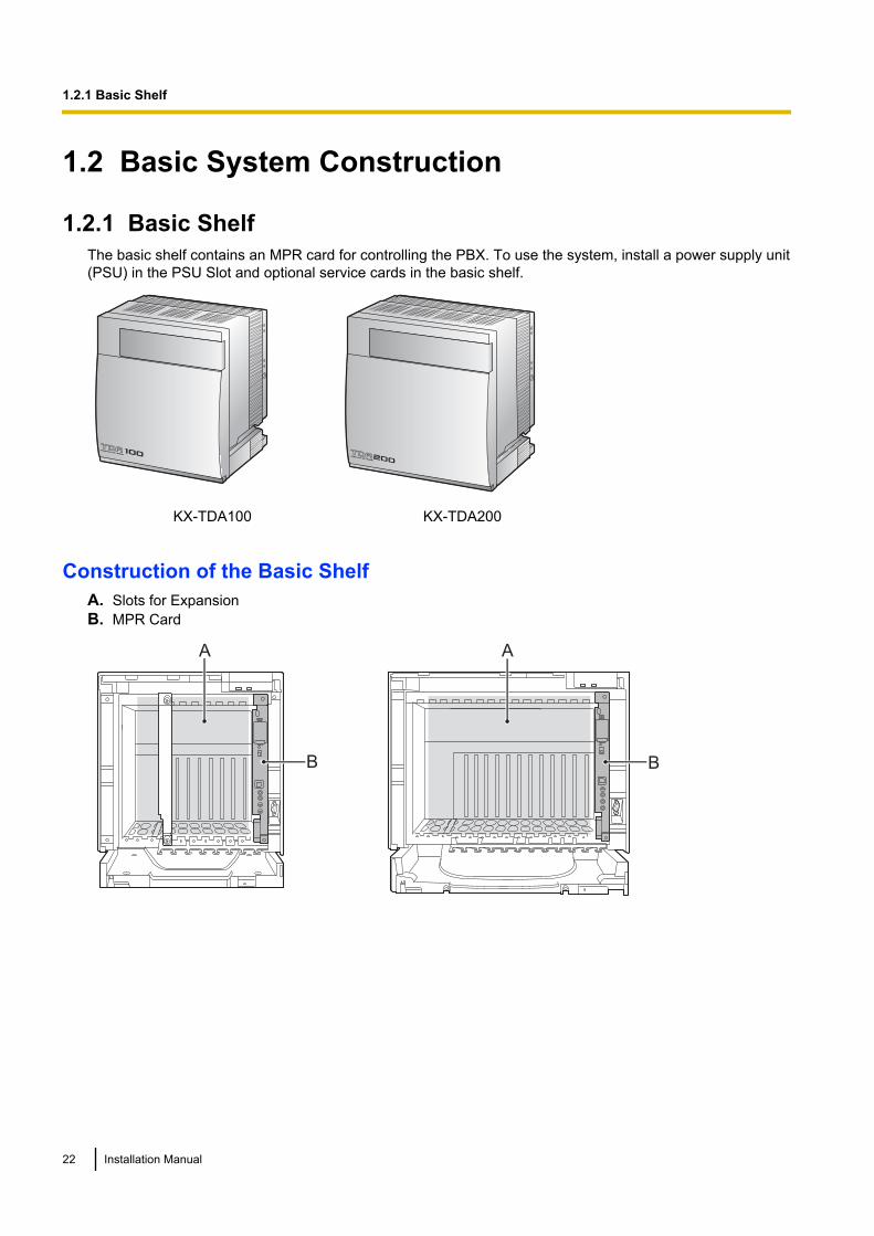
1.2.1 Basic ShelfThe basic shelf contains an MPR card for controlling the PBX. To use the system, install a power supply unit(PSU) in the PSU Slot and optional service cards in the basic shelf.
KX-TDA100 KX-TDA200
Construction of the Basic ShelfA. Slots for ExpansionB. MPR Card
A
B
A
B
22 Installation Manual
1.2.1 Basic Shelf
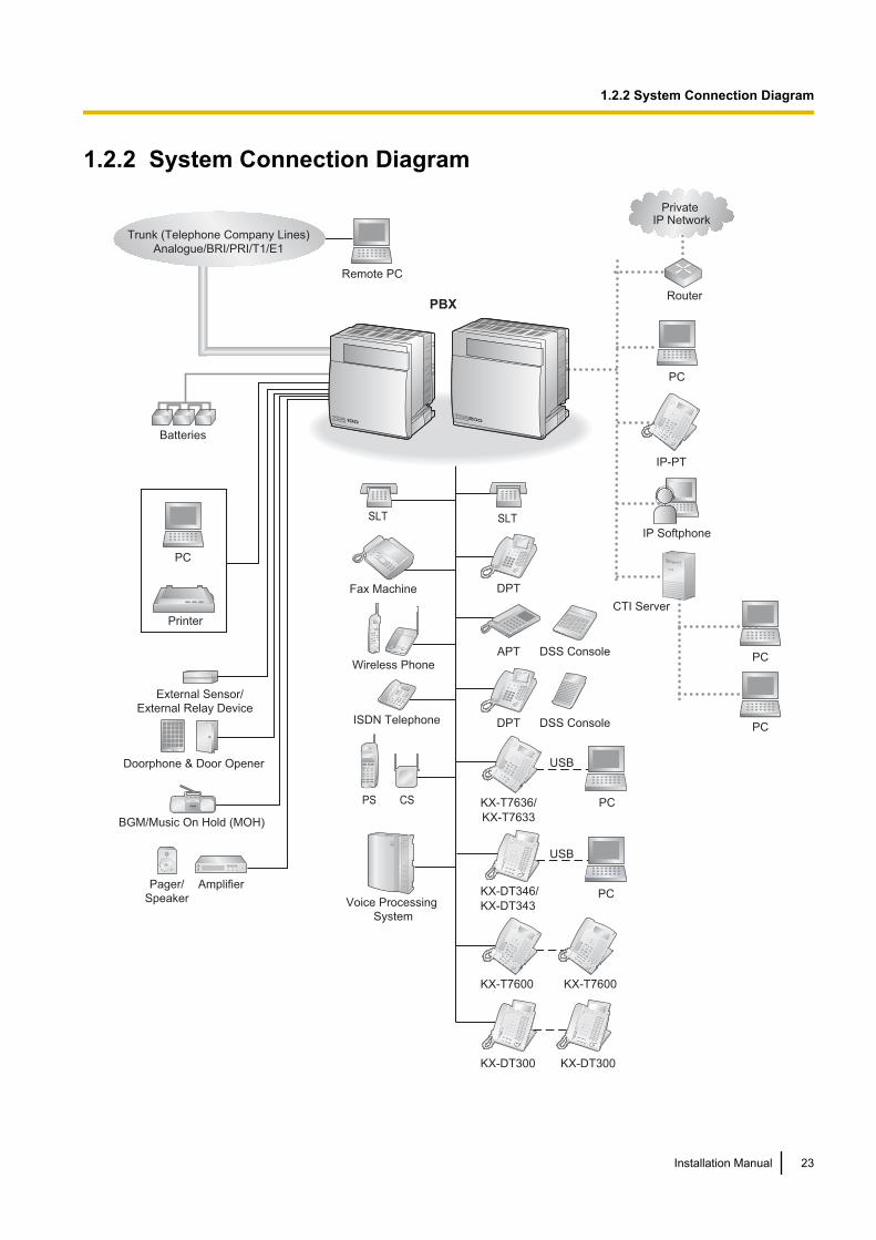
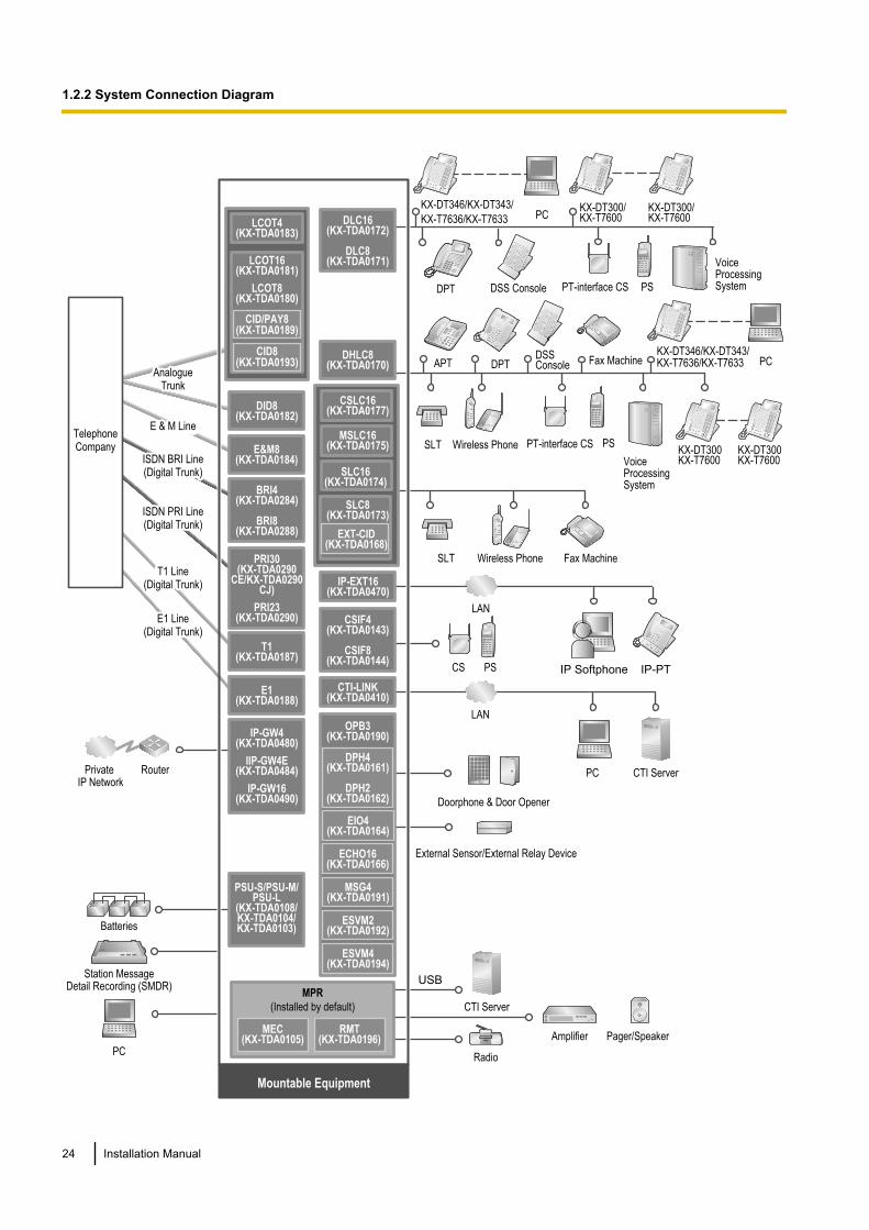
1.2.2 System Connection Diagram
Doorphone & Door Opener
BGM/Music On Hold (MOH)
Pager/
Speaker
Batteries
Voice Processing
System
KX-T7636/
KX-T7633
Remote PC
PC
Printer
Trunk (Telephone Company Lines)
Analogue/BRI/PRI/T1/E1
PBX
SLT
CSPS
Wireless Phone
Fax Machine
PC
USB
APT
DPTISDN Telephone
Amplifier
SLT
DPT
DSS Console
DSS Console
KX-T7600 KX-T7600
External Sensor/
External Relay Device
Router
Private IP Network
PC
IP Softphone
CTI Server
PC
PC
IP-PT
PC
USB
KX-DT346/
KX-DT343
KX-DT300 KX-DT300
Installation Manual 23
1.2.2 System Connection Diagram
External Sensor/External Relay Device
USB
SLT Wireless Phone
Fax Machine
PCKX-DT346/KX-DT343/
KX-T7636/KX-T7633
DSS Console
Doorphone & Door Opener
PT-interface CS PS
Private IP Network
Station MessageDetail Recording (SMDR)
PC
Router
ISDN BRI LineISDN BRI Line(Digital Trunk)(Digital Trunk)ISDN BRI Line(Digital Trunk)
ISDN PRI LineISDN PRI Line(Digital Trunk)(Digital Trunk)ISDN PRI Line(Digital Trunk)
AnalogueAnalogueTrunkTrunk
AnalogueTrunk
E & M LineE & M LineE & M Line
SLT Wireless Phone Fax Machine
Mountable Equipment
DPT
APT DPTDSSConsole
PT-interface CS PS
Voice Processing System
Batteries
Radio
Amplifier Pager/Speaker
CTI Server
LCOT16(KX-TDA0181)
LCOT8(KX-TDA0180)
DLC16(KX-TDA0172)
DLC8(KX-TDA0171)
DHLC8(KX-TDA0170)
IP-GW4(KX-TDA0480)
IIP-GW4E(KX-TDA0484)
IP-GW16(KX-TDA0490)
PRI30(KX-TDA0290
CE/KX-TDA0290CJ)
PRI23(KX-TDA0290)
BRI4(KX-TDA0284)
BRI8(KX-TDA0288)
T1 LineT1 Line(Digital Trunk)(Digital Trunk)
T1 Line(Digital Trunk)
E1 LineE1 Line(Digital Trunk)(Digital Trunk)
E1 Line(Digital Trunk)
E1(KX-TDA0188)
T1(KX-TDA0187)
E&M8(KX-TDA0184)
DID8(KX-TDA0182)
PSU-S/PSU-M/PSU-L
(KX-TDA0108/KX-TDA0104/KX-TDA0103)
MPR
(Installed by default)
RMT(KX-TDA0196)
MEC(KX-TDA0105)
LCOT4(KX-TDA0183)
OPB3(KX-TDA0190)
DPH4(KX-TDA0161)
DPH2(KX-TDA0162)
ECHO16(KX-TDA0166)
MSG4(KX-TDA0191)
ESVM2(KX-TDA0192)
ESVM4(KX-TDA0194)
EIO4(KX-TDA0164)
MSLC16(KX-TDA0175)
CSLC16(KX-TDA0177)
SLC8(KX-TDA0173)
EXT-CID(KX-TDA0168)
SLC16(KX-TDA0174)
Voice Processing System
CS PS
CSIF4(KX-TDA0143)
CSIF8(KX-TDA0144)
PC
LAN
CTI Server
CTI-LINK(KX-TDA0410)
IP-EXT16(KX-TDA0470)
IP-PTIP Softphone
LAN
KX-DT300/KX-T7600
KX-DT300/KX-T7600
PCKX-DT346/KX-DT343/KX-T7636/KX-T7633
KX-DT300 KX-T7600
KX-DT300 KX-T7600
LCOT4(KX-TDA0183)
LCOT16(KX-TDA0181)
LCOT8(KX-TDA0180)
CID/PAY8(KX-TDA0189)
CID8(KX-TDA0193)
TelephoneCompany
24 Installation Manual
1.2.2 System Connection Diagram
1.3 Optional Equipment
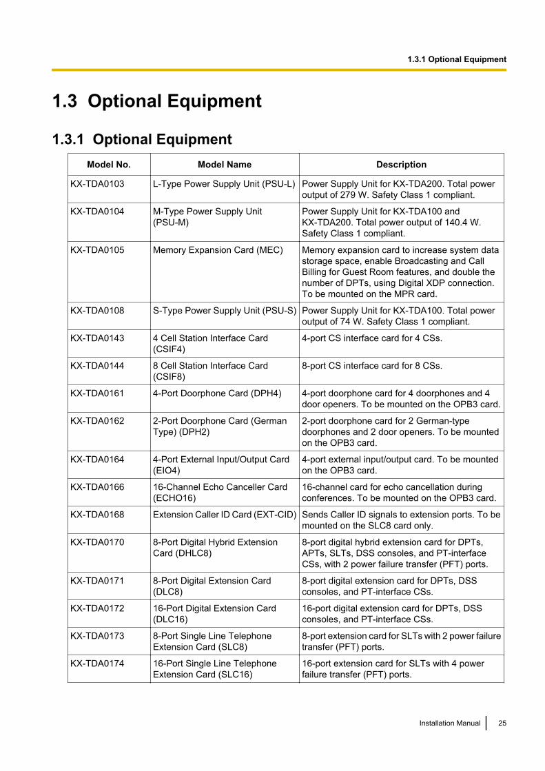
1.3.1 Optional EquipmentModel No. Model Name Description
KX-TDA0103 L-Type Power Supply Unit (PSU-L) Power Supply Unit for KX-TDA200. Total poweroutput of 279 W. Safety Class 1 compliant.
KX-TDA0104 M-Type Power Supply Unit(PSU-M)
Power Supply Unit for KX-TDA100 andKX-TDA200. Total power output of 140.4 W.Safety Class 1 compliant.
KX-TDA0105 Memory Expansion Card (MEC) Memory expansion card to increase system datastorage space, enable Broadcasting and CallBilling for Guest Room features, and double thenumber of DPTs, using Digital XDP connection.To be mounted on the MPR card.
KX-TDA0108 S-Type Power Supply Unit (PSU-S) Power Supply Unit for KX-TDA100. Total poweroutput of 74 W. Safety Class 1 compliant.
KX-TDA0143 4 Cell Station Interface Card(CSIF4)
4-port CS interface card for 4 CSs.
KX-TDA0144 8 Cell Station Interface Card(CSIF8)
8-port CS interface card for 8 CSs.
KX-TDA0161 4-Port Doorphone Card (DPH4) 4-port doorphone card for 4 doorphones and 4door openers. To be mounted on the OPB3 card.
KX-TDA0162 2-Port Doorphone Card (GermanType) (DPH2)
2-port doorphone card for 2 German-typedoorphones and 2 door openers. To be mountedon the OPB3 card.
KX-TDA0164 4-Port External Input/Output Card(EIO4)
4-port external input/output card. To be mountedon the OPB3 card.
KX-TDA0166 16-Channel Echo Canceller Card(ECHO16)
16-channel card for echo cancellation duringconferences. To be mounted on the OPB3 card.
KX-TDA0168 Extension Caller ID Card (EXT-CID) Sends Caller ID signals to extension ports. To bemounted on the SLC8 card only.
KX-TDA0170 8-Port Digital Hybrid ExtensionCard (DHLC8)
8-port digital hybrid extension card for DPTs,APTs, SLTs, DSS consoles, and PT-interfaceCSs, with 2 power failure transfer (PFT) ports.
KX-TDA0171 8-Port Digital Extension Card(DLC8)
8-port digital extension card for DPTs, DSSconsoles, and PT-interface CSs.
KX-TDA0172 16-Port Digital Extension Card(DLC16)
16-port digital extension card for DPTs, DSSconsoles, and PT-interface CSs.
KX-TDA0173 8-Port Single Line TelephoneExtension Card (SLC8)
8-port extension card for SLTs with 2 power failuretransfer (PFT) ports.
KX-TDA0174 16-Port Single Line TelephoneExtension Card (SLC16)
16-port extension card for SLTs with 4 powerfailure transfer (PFT) ports.
Installation Manual 25
1.3.1 Optional Equipment

Model No. Model Name Description
KX-TDA0175 16-Port Single Line TelephoneExtension with Message Lamp Card(MSLC16)
16-port extension card for SLTs with MessageWaiting Lamp control and 4 power failure transfer(PFT) ports. Maximum power output of 160 V/90V for Message Waiting Lamp control.
KX-TDA0177 16-Port Single Line TelephoneExtension Card with Caller ID(CSLC16)
16-port extension card for SLTs with Caller ID(FSK) and 4 power failure transfer (PFT) ports.
KX-TDA0180 8-Port Analogue Trunk Card(LCOT8)
8-port analogue trunk card with 2 power failuretransfer (PFT) ports.
KX-TDA0181 16-Port Analogue Trunk Card(LCOT16)
16-port analogue trunk card with 4 power failuretransfer (PFT) ports.
KX-TDA0182 8-Port DID Card (DID8) 8-port DID trunk card.
KX-TDA0183 4-Port Analogue Trunk Card(LCOT4)
4-port analogue trunk card with 2 power failuretransfer (PFT) ports.
KX-TDA0184 8-Port E & M Trunk Card (E&M8) 8-port E & M (TIE) trunk card. Type 5 support.
KX-TDA0187 T-1 Trunk Card (T1) 1-port T1 trunk card. EIA/TIA standard compliant.
KX-TDA0188 E-1 Trunk Card (E1) 1-port E1 trunk card. ITU-T standard compliant.
KX-TDA0189 8-Port Caller ID/Pay Tone Card(CID/PAY8)
8-port Caller ID signal type FSK/FSK (with CallWaiting Caller ID [Visual Caller ID])/DTMF, and8-port Pay Tone Service (12 kHz/16 kHz). To bemounted on the ELCOT16 card.
KX-TDA0190 Optional 3-Slot Base Card (OPB3) Optional 3-slot base card for mounting a maximumof 3 optional service cards from the following:MSG4, ESVM4, ESVM2, DPH4, DPH2 or EIO4card.
KX-TDA0191 4-Channel Message Card (MSG4) 4-channel message card. To be mounted on theOPB3 card.
KX-TDA0192 2-Channel Simplified VoiceMessage Card (ESVM2)
2-channel simplified voice message card forBuilt-in Simplified Voice Message feature. Alsosupports MSG card features. To be mounted onthe OPB3 card.
KX-TDA0193 8-Port Caller ID Card (CID8) 8-port Caller ID signal type FSK/FSK (with CallWaiting Caller ID [Visual Caller ID])/DTMF. To bemounted on the ELCOT16 card.
KX-TDA0194 4-Channel Simplified VoiceMessage Card (ESVM4)
4-channel simplified voice message card forBuilt-in Simplified Voice Message feature. Alsosupports MSG card features. To be mounted onthe OPB3 card.
KX-TDA0196 Remote Card (RMT) Analogue modem card for remote communicationwith the PBX. ITU-T V.90 support. To be mountedon the MPR card.
26 Installation Manual
1.3.1 Optional Equipment
Model No. Model Name Description
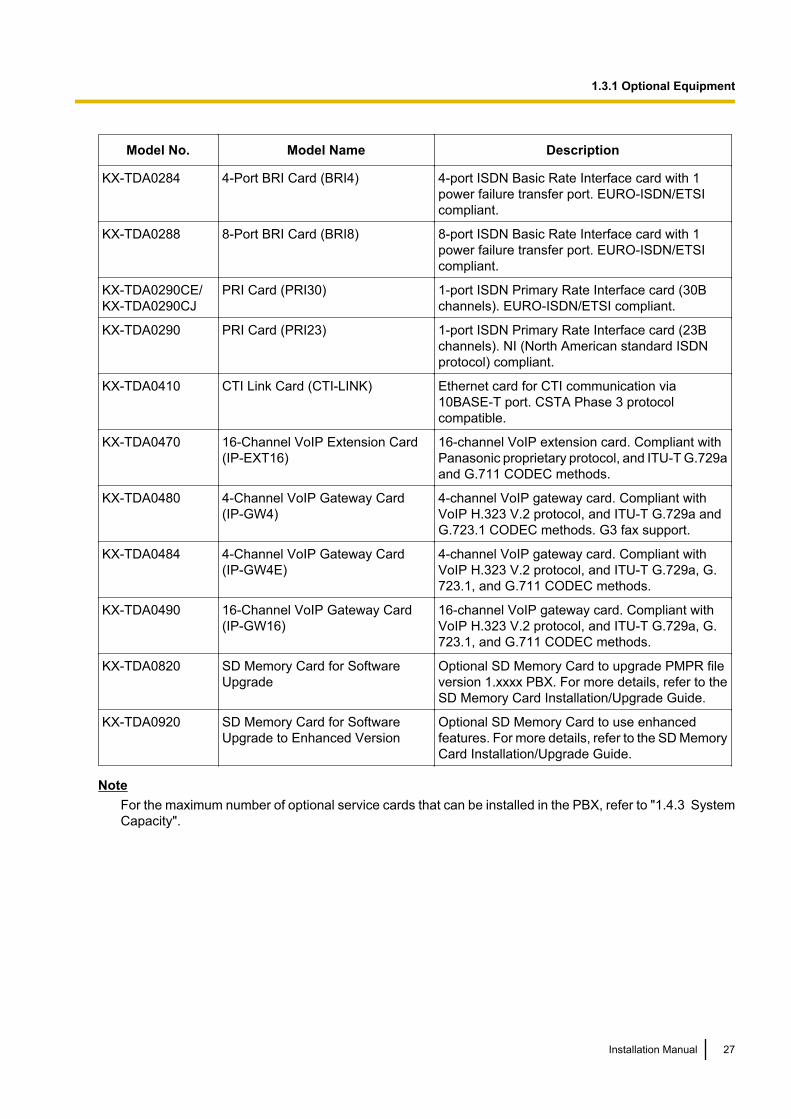
KX-TDA0284 4-Port BRI Card (BRI4) 4-port ISDN Basic Rate Interface card with 1power failure transfer port. EURO-ISDN/ETSIcompliant.
KX-TDA0288 8-Port BRI Card (BRI8) 8-port ISDN Basic Rate Interface card with 1power failure transfer port. EURO-ISDN/ETSIcompliant.
KX-TDA0290CE/KX-TDA0290CJ
PRI Card (PRI30) 1-port ISDN Primary Rate Interface card (30Bchannels). EURO-ISDN/ETSI compliant.
KX-TDA0290 PRI Card (PRI23) 1-port ISDN Primary Rate Interface card (23Bchannels). NI (North American standard ISDNprotocol) compliant.
KX-TDA0410 CTI Link Card (CTI-LINK) Ethernet card for CTI communication via10BASE-T port. CSTA Phase 3 protocolcompatible.
KX-TDA0470 16-Channel VoIP Extension Card(IP-EXT16)
16-channel VoIP extension card. Compliant withPanasonic proprietary protocol, and ITU-T G.729aand G.711 CODEC methods.
KX-TDA0480 4-Channel VoIP Gateway Card(IP-GW4)
4-channel VoIP gateway card. Compliant withVoIP H.323 V.2 protocol, and ITU-T G.729a andG.723.1 CODEC methods. G3 fax support.
KX-TDA0484 4-Channel VoIP Gateway Card(IP-GW4E)
4-channel VoIP gateway card. Compliant withVoIP H.323 V.2 protocol, and ITU-T G.729a, G.723.1, and G.711 CODEC methods.
KX-TDA0490 16-Channel VoIP Gateway Card(IP-GW16)
16-channel VoIP gateway card. Compliant withVoIP H.323 V.2 protocol, and ITU-T G.729a, G.723.1, and G.711 CODEC methods.
KX-TDA0820 SD Memory Card for SoftwareUpgrade
Optional SD Memory Card to upgrade PMPR fileversion 1.xxxx PBX. For more details, refer to theSD Memory Card Installation/Upgrade Guide.
KX-TDA0920 SD Memory Card for SoftwareUpgrade to Enhanced Version
Optional SD Memory Card to use enhancedfeatures. For more details, refer to the SD MemoryCard Installation/Upgrade Guide.
NoteFor the maximum number of optional service cards that can be installed in the PBX, refer to "1.4.3 SystemCapacity".
Installation Manual 27
1.3.1 Optional Equipment
1.4 Specifications
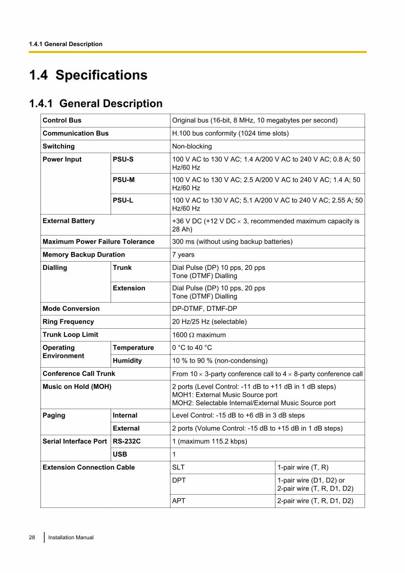
1.4.1 General DescriptionControl Bus Original bus (16-bit, 8 MHz, 10 megabytes per second)
Communication Bus H.100 bus conformity (1024 time slots)
Switching Non-blocking
Power Input PSU-S 100 V AC to 130 V AC; 1.4 A/200 V AC to 240 V AC; 0.8 A; 50Hz/60 Hz
PSU-M 100 V AC to 130 V AC; 2.5 A/200 V AC to 240 V AC; 1.4 A; 50Hz/60 Hz
PSU-L 100 V AC to 130 V AC; 5.1 A/200 V AC to 240 V AC; 2.55 A; 50Hz/60 Hz
External Battery +36 V DC (+12 V DC ´ 3, recommended maximum capacity is28 Ah)
Maximum Power Failure Tolerance 300 ms (without using backup batteries)
Memory Backup Duration 7 years
Dialling Trunk Dial Pulse (DP) 10 pps, 20 ppsTone (DTMF) Dialling
Extension Dial Pulse (DP) 10 pps, 20 ppsTone (DTMF) Dialling
Mode Conversion DP-DTMF, DTMF-DP
Ring Frequency 20 Hz/25 Hz (selectable)
Trunk Loop Limit 1600 W maximum
OperatingEnvironment
Temperature 0 °C to 40 °C
Humidity 10 % to 90 % (non-condensing)
Conference Call Trunk From 10 ´ 3-party conference call to 4 ´ 8-party conference call
Music on Hold (MOH) 2 ports (Level Control: -11 dB to +11 dB in 1 dB steps)MOH1: External Music Source portMOH2: Selectable Internal/External Music Source port
Paging Internal Level Control: -15 dB to +6 dB in 3 dB steps
External 2 ports (Volume Control: -15 dB to +15 dB in 1 dB steps)
Serial Interface Port RS-232C 1 (maximum 115.2 kbps)
USB 1
Extension Connection Cable SLT 1-pair wire (T, R)
DPT 1-pair wire (D1, D2) or2-pair wire (T, R, D1, D2)
APT 2-pair wire (T, R, D1, D2)
28 Installation Manual
1.4.1 General Description

PT-interface CS 1-pair wire (D1, D2)
PT-interface CS (High-density) 4-pair wire (D1, D2)
DSS Console and Add-on KeyModule
1-pair wire (D1, D2)
Dimension KX-TDA100 334 mm (W) ´ 390 mm (H) ´ 270 mm (D)
KX-TDA200 430 mm (W) ´ 415 mm (H) ´ 270 mm (D)
Weight (when fullymounted)
KX-TDA100 Under 12 kg
KX-TDA200 Under 16 kg
Installation Manual 29
1.4.1 General Description
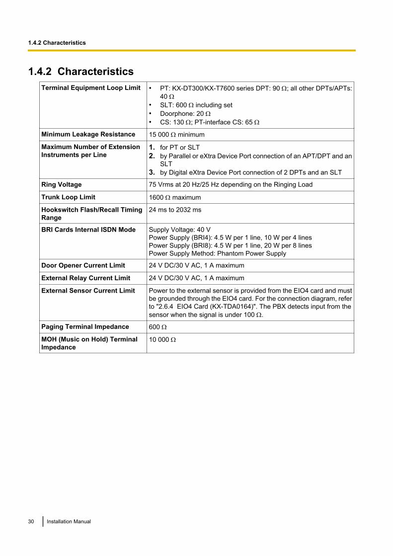
1.4.2 CharacteristicsTerminal Equipment Loop Limit • PT: KX-DT300/KX-T7600 series DPT: 90 W; all other DPTs/APTs:
40 W• SLT: 600 W including set• Doorphone: 20 W• CS: 130 W; PT-interface CS: 65 W
Minimum Leakage Resistance 15 000 W minimum
Maximum Number of ExtensionInstruments per Line
1. for PT or SLT2. by Parallel or eXtra Device Port connection of an APT/DPT and an
SLT3. by Digital eXtra Device Port connection of 2 DPTs and an SLT
Ring Voltage 75 Vrms at 20 Hz/25 Hz depending on the Ringing Load
Trunk Loop Limit 1600 W maximum
Hookswitch Flash/Recall TimingRange
24 ms to 2032 ms
BRI Cards Internal ISDN Mode Supply Voltage: 40 VPower Supply (BRI4): 4.5 W per 1 line, 10 W per 4 linesPower Supply (BRI8): 4.5 W per 1 line, 20 W per 8 linesPower Supply Method: Phantom Power Supply
Door Opener Current Limit 24 V DC/30 V AC, 1 A maximum
External Relay Current Limit 24 V DC/30 V AC, 1 A maximum
External Sensor Current Limit Power to the external sensor is provided from the EIO4 card and mustbe grounded through the EIO4 card. For the connection diagram, referto "2.6.4 EIO4 Card (KX-TDA0164)". The PBX detects input from thesensor when the signal is under 100 W.
Paging Terminal Impedance 600 W
MOH (Music on Hold) TerminalImpedance
10 000 W
30 Installation Manual
1.4.2 Characteristics
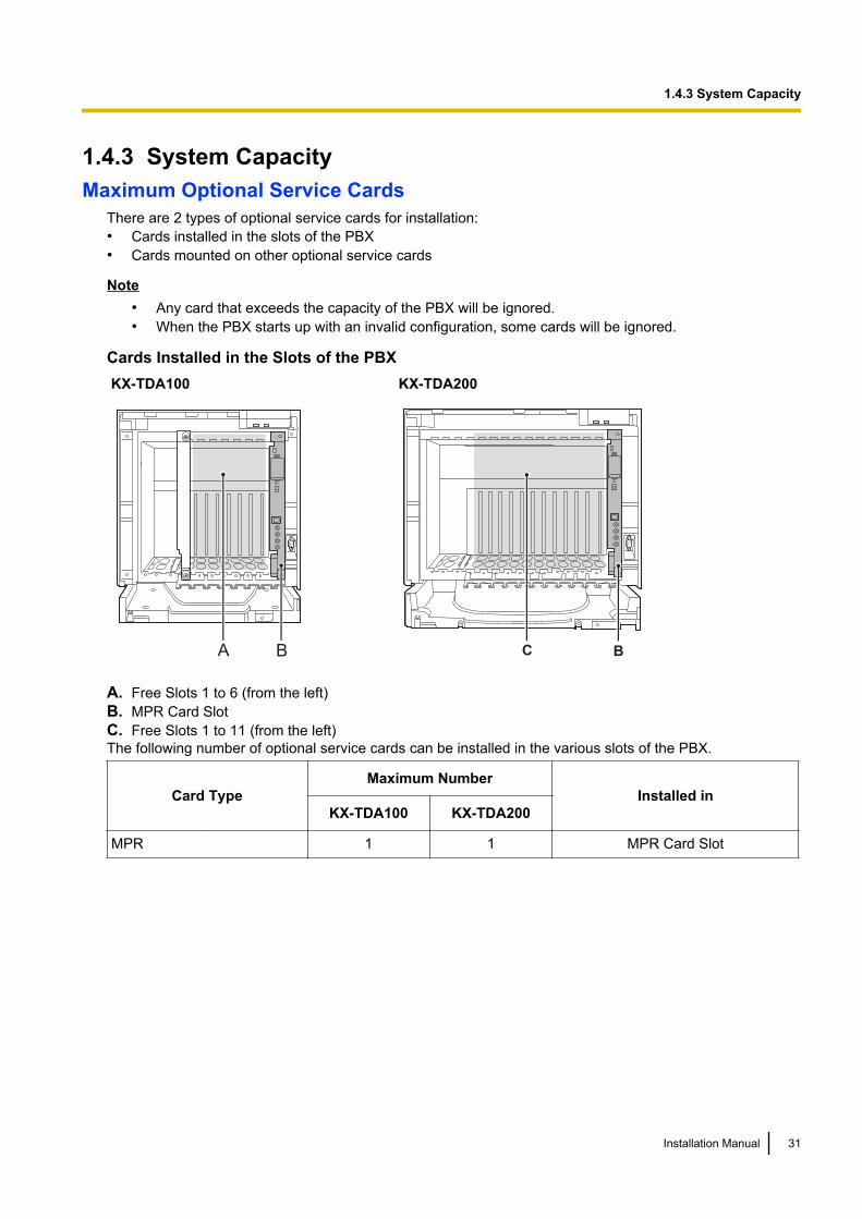
1.4.3 System CapacityMaximum Optional Service Cards
There are 2 types of optional service cards for installation:• Cards installed in the slots of the PBX• Cards mounted on other optional service cards
Note• Any card that exceeds the capacity of the PBX will be ignored.• When the PBX starts up with an invalid configuration, some cards will be ignored.
Cards Installed in the Slots of the PBXKX-TDA100 KX-TDA200
A B C B
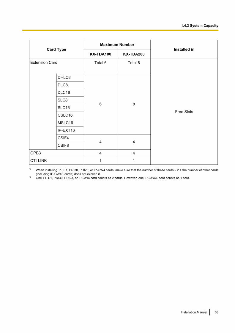
A. Free Slots 1 to 6 (from the left)B. MPR Card SlotC. Free Slots 1 to 11 (from the left)The following number of optional service cards can be installed in the various slots of the PBX.
Card TypeMaximum Number
Installed inKX-TDA100 KX-TDA200
MPR 1 1 MPR Card Slot
Installation Manual 31
1.4.3 System Capacity

Card TypeMaximum Number
Installed inKX-TDA100 KX-TDA200
Trunk Card Total 6*1 Total 8*2
Free Slots
LCOT4
6 8
LCOT8
LCOT16
DID8
E&M8
BRI4
BRI8
T1
4 4E1
PRI23
PRI30
IP-GW4
4 4IP-GW4E
IP-GW16
32 Installation Manual
1.4.3 System Capacity
Card TypeMaximum Number
Installed inKX-TDA100 KX-TDA200
Extension Card Total 6 Total 8
Free Slots
DHLC8
6 8
DLC8
DLC16
SLC8
SLC16
CSLC16
MSLC16
IP-EXT16
CSIF44 4
CSIF8
OPB3 4 4
CTI-LINK 1 1
*1 When installing T1, E1, PRI30, PRI23, or IP-GW4 cards, make sure that the number of these cards ´ 2 + the number of other cards(including IP-GW4E cards) does not exceed 8.
*2 One T1, E1, PRI30, PRI23, or IP-GW4 card counts as 2 cards. However, one IP-GW4E card counts as 1 card.
Installation Manual 33
1.4.3 System Capacity
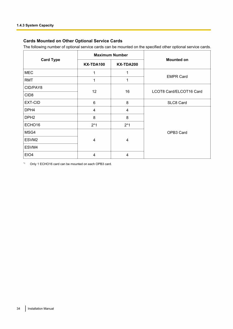
Cards Mounted on Other Optional Service CardsThe following number of optional service cards can be mounted on the specified other optional service cards.
Card TypeMaximum Number
Mounted onKX-TDA100 KX-TDA200
MEC 1 1EMPR Card
RMT 1 1
CID/PAY812 16 LCOT8 Card/ELCOT16 Card
CID8
EXT-CID 6 8 SLC8 Card
DPH4 4 4
OPB3 Card
DPH2 8 8
ECHO16 2*1 2*1
MSG4
4 4ESVM2
ESVM4
EIO4 4 4
*1 Only 1 ECHO16 card can be mounted on each OPB3 card.
34 Installation Manual
1.4.3 System Capacity
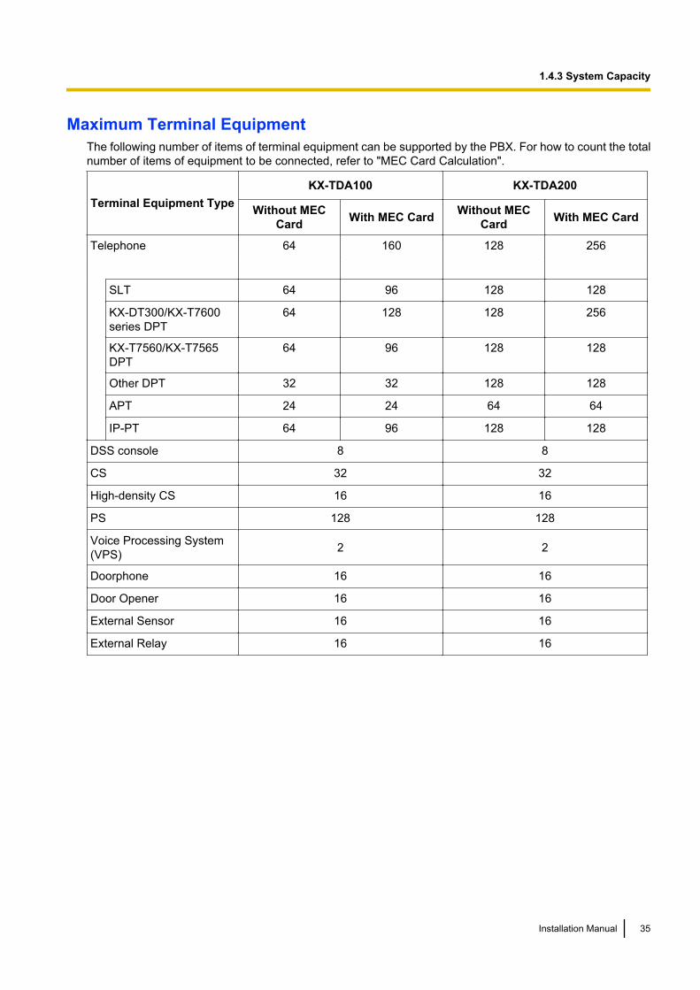
Maximum Terminal EquipmentThe following number of items of terminal equipment can be supported by the PBX. For how to count the totalnumber of items of equipment to be connected, refer to "MEC Card Calculation".
Terminal Equipment TypeKX-TDA100 KX-TDA200
Without MECCard With MEC Card Without MEC
Card With MEC Card
Telephone 64 160 128 256
SLT 64 96 128 128
KX-DT300/KX-T7600series DPT
64 128 128 256
KX-T7560/KX-T7565DPT
64 96 128 128
Other DPT 32 32 128 128
APT 24 24 64 64
IP-PT 64 96 128 128
DSS console 8 8
CS 32 32
High-density CS 16 16
PS 128 128
Voice Processing System(VPS) 2 2
Doorphone 16 16
Door Opener 16 16
External Sensor 16 16
External Relay 16 16
Installation Manual 35
1.4.3 System Capacity
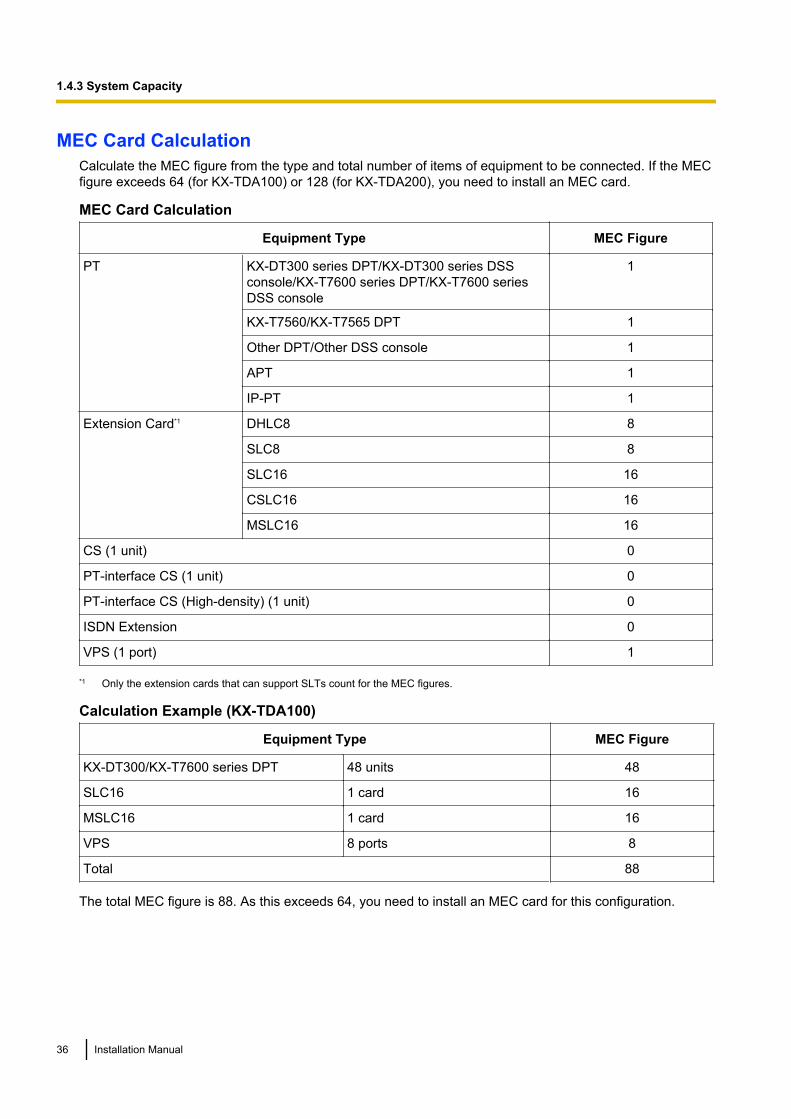
MEC Card CalculationCalculate the MEC figure from the type and total number of items of equipment to be connected. If the MECfigure exceeds 64 (for KX-TDA100) or 128 (for KX-TDA200), you need to install an MEC card.
MEC Card Calculation
Equipment Type MEC Figure
PT KX-DT300 series DPT/KX-DT300 series DSSconsole/KX-T7600 series DPT/KX-T7600 seriesDSS console
1
KX-T7560/KX-T7565 DPT 1
Other DPT/Other DSS console 1
APT 1
IP-PT 1
Extension Card*1 DHLC8 8
SLC8 8
SLC16 16
CSLC16 16
MSLC16 16
CS (1 unit) 0
PT-interface CS (1 unit) 0
PT-interface CS (High-density) (1 unit) 0
ISDN Extension 0
VPS (1 port) 1
*1 Only the extension cards that can support SLTs count for the MEC figures.
Calculation Example (KX-TDA100)
Equipment Type MEC Figure
KX-DT300/KX-T7600 series DPT 48 units 48
SLC16 1 card 16
MSLC16 1 card 16
VPS 8 ports 8
Total 88
The total MEC figure is 88. As this exceeds 64, you need to install an MEC card for this configuration.
36 Installation Manual
1.4.3 System Capacity
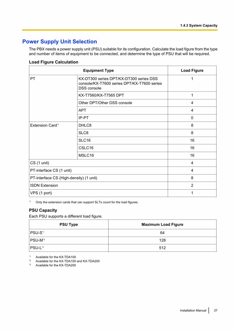
Power Supply Unit SelectionThe PBX needs a power supply unit (PSU) suitable for its configuration. Calculate the load figure from the typeand number of items of equipment to be connected, and determine the type of PSU that will be required.
Load Figure Calculation
Equipment Type Load Figure
PT KX-DT300 series DPT/KX-DT300 series DSSconsole/KX-T7600 series DPT/KX-T7600 seriesDSS console
1
KX-T7560/KX-T7565 DPT 1
Other DPT/Other DSS console 4
APT 4
IP-PT 0
Extension Card*1 DHLC8 8
SLC8 8
SLC16 16
CSLC16 16
MSLC16 16
CS (1 unit) 4
PT-interface CS (1 unit) 4
PT-interface CS (High-density) (1 unit) 8
ISDN Extension 2
VPS (1 port) 1
*1 Only the extension cards that can support SLTs count for the load figures.
PSU CapacityEach PSU supports a different load figure.
PSU Type Maximum Load Figure
PSU-S*1 64
PSU-M*2 128
PSU-L*3 512
*1 Available for the KX-TDA100*2 Available for the KX-TDA100 and KX-TDA200*3 Available for the KX-TDA200
Installation Manual 37
1.4.3 System Capacity
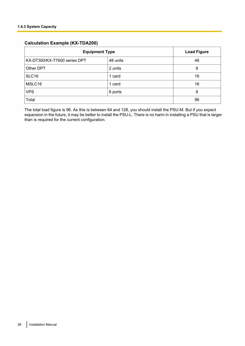
Calculation Example (KX-TDA200)
Equipment Type Load Figure
KX-DT300/KX-T7600 series DPT 48 units 48
Other DPT 2 units 8
SLC16 1 card 16
MSLC16 1 card 16
VPS 8 ports 8
Total 96
The total load figure is 96. As this is between 64 and 128, you should install the PSU-M. But if you expectexpansion in the future, it may be better to install the PSU-L. There is no harm in installing a PSU that is largerthan is required for the current configuration.
38 Installation Manual
1.4.3 System Capacity
Section 2
Installation
This section describes the procedures to install thePBX. Detailed instructions for planning the installationsite, installing the shelves and optional service cards,and cabling of peripheral equipment are provided.Further information on system expansion and peripheralequipment installation is included.
Installation Manual 39
2.1 Before Installation
2.1.1 Before InstallationPlease read the following notes concerning installation and connection before installing the PBX and terminalequipment.Be sure to comply with all applicable laws, regulations, and guidelines.
Safety Installation InstructionsWhen installing telephone wiring, basic safety precautions should always be followed to reduce the risk of fire,electric shock and injury to persons, including the following:1. Never install telephone wiring during a lightning storm.2. Never install telephone jacks in wet locations unless the jack is specifically designed for wet locations.3. Never touch uninsulated telephone wires or terminals unless the telephone line has been disconnected at
the network interface.4. Use caution when installing or modifying telephone lines.
Installation PrecautionsThis set is made for wall mounting (KX-TDA100/KX-TDA200) or floor standing (KX-TDA200 only), and shouldbe installed in a location where it is accessible for inspections and maintenance.To prevent malfunction, noise, or discolouration, avoid installing the system in the following locations:1. In direct sunlight and hot, cold, or humid places. (Temperature range: 0 °C to 40 °C)2. Areas where sulfuric gases may be present, such as near thermal springs.3. Areas where shocks or vibrations are frequent or strong.4. High-dust areas, or places the system may come into contact with water or oil.5. Near devices that generate high frequencies, such as sewing machines or electric welders.6. On or near computers, telexes, or other office equipment, as well as microwave ovens or air conditioners.
(It is preferable not to install the system in the same room as the above equipment.)7. Within 1.8 m of radios and televisions. (Both the PBX and PTs should be at least 1.8 m away from such
devices).8. Locations where other objects will obstruct the area around the PBX. Be especially careful to leave at least
20 cm of space above and 10 cm to the sides of the PBX for ventilation.9. Do not block the openings of the PBX.10. Do not stack up the optional service cards.
Wiring PrecautionsBe sure to follow these instructions when wiring the unit:1. Do not run unshielded telephone cables near AC power cables, computer cables, AC power sources, etc.
When running cables near other noise-generating devices or cables, use shielded telephone cables orshield the telephone cables with metal tubing.
2. If cables are run on the floor, use protectors to prevent the cables from being stepped on. Avoid runningcables under carpets.
3. Avoid using the same AC outlet for computers, telexes, and other office equipment, as noise generated bysuch equipment may hamper system performance or interrupt the system.
4. Use 2-pair telephone cables when connecting PTs.Use 1-pair telephone cables when connecting SLTs, data terminals, answering machines, computers,Voice Processing Systems, etc.
40 Installation Manual
2.1.1 Before Installation
5. Unplug the system from its power source when wiring, and plug the system back in only after all wiring iscompleted.
6. Mis-wiring may cause the PBX to operate improperly. Refer to "Section 2 Installation" when wiring thesystem.
7. If an extension does not operate properly, disconnect the telephone from the extension line and connectit again, or turn off the PBX using the power switch, then turn it on again.
8. For safety purposes this unit is equipped with an earthed plug. If you do not have an earthed outlet, pleasehave one installed. Do not bypass this safety feature by tampering with the plug.
9. Use twisted pair cable for trunk connection.10. Trunks should be installed with surge protectors. For details, refer to "2.2.14 Surge Protector Installation".
Installation Manual 41
2.1.1 Before Installation

2.2 Installation of the PBX
2.2.1 UnpackingUnpack the box and check the items below:
KX-TDA100 KX-TDA200
Main Unit 1 1
AC Cord with a Ferrite Core*1 1*2 1*2
Metal Bracket 1 1
Screw A 3 4
Screw B (Black) 2 6
Anchor Plug 3 4
Mini Plug (for pager and music source) 4 4
SD Memory Card 1 1
*1 In Canada, there is no ferrite core attached to the AC cord.*2 KX-TDA100BX/KX-TDA200BX is supplied with 2 types of AC cord. Please use whichever is appropriate for the country/area.
42 Installation Manual
2.2.1 Unpacking
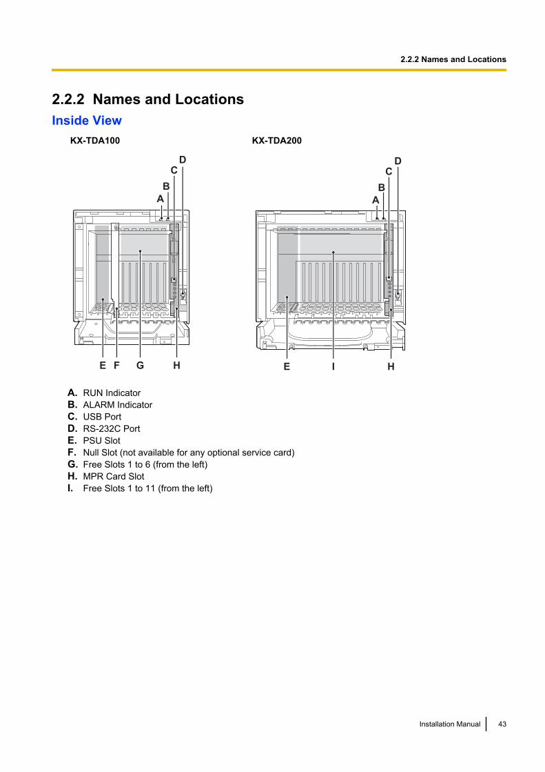
2.2.2 Names and LocationsInside View
KX-TDA100 KX-TDA200
F
DC
A
B
GE H
DC
A
B
IE H
A. RUN IndicatorB. ALARM IndicatorC. USB PortD. RS-232C PortE. PSU SlotF. Null Slot (not available for any optional service card)G. Free Slots 1 to 6 (from the left)H. MPR Card SlotI. Free Slots 1 to 11 (from the left)
Installation Manual 43
2.2.2 Names and Locations
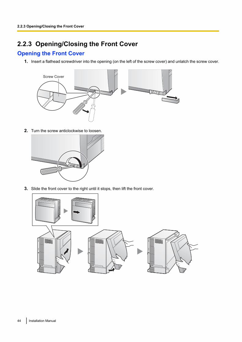
2.2.3 Opening/Closing the Front CoverOpening the Front Cover
1. Insert a flathead screwdriver into the opening (on the left of the screw cover) and unlatch the screw cover.
Screw Cover
2. Turn the screw anticlockwise to loosen.
3. Slide the front cover to the right until it stops, then lift the front cover.
44 Installation Manual
2.2.3 Opening/Closing the Front Cover

Closing the Front Cover1. Hook the front cover onto the shelf (line up the protrusions on the cover with the receptacles on the shelf).
Then slide the front cover to the left until it locks.
2. Turn the screw clockwise to tighten.
3. Secure the screw cover.
1
2
CAUTION• For safety reasons, close the front cover and tighten the screw before operating the PBX.• Do not forget to tighten the screw before securing the screw cover.
Installation Manual 45
2.2.3 Opening/Closing the Front Cover

2.2.4 Installing/Replacing the Power Supply UnitFunction
PSU Type Lower/Upper Input Voltage Range Current Input Frequency
PSU-S Lower: 100 V AC to 130 V AC 1.4 A
50 Hz or 60 Hz
(for KX-TDA100) Upper: 200 V AC to 240 V AC 0.8 A
PSU-M Lower: 100 V AC to 130 V AC 2.5 A
(for KX-TDA100/KX-TDA200)
Upper: 200 V AC to 240 V AC 1.4 A
PSU-L Lower: 100 V AC to 130 V AC 5.1 A
(for KX-TDA200) Upper: 200 V AC to 240 V AC 2.55 A
AC Inlet
Power Switch
AC Inlet
Power Switch
PSU-S PSU-M/PSU-L
Battery Switch
Earth Terminal
Battery Switch
Earth Terminal
Battery ConnectorBattery Connector
Accessories and User-supplied ItemsAccessories (included): Screws ´ 4User-supplied (not included): Earthing wire, Back-up Battery Cable (KX-A228 for PSU-S and PSU-M, orKX-A229 for PSU-L)
Note• For details about frame earth connection, refer to "2.2.5 Frame Earth Connection".• For details about backup batteries connection, refer to "2.2.6 Backup Battery Connection".
Safety InstructionsEach PSU complies with Safety Class 1 of IEC60950, EN60950, UL60950,CAN/CSA-C22.2 No.60950, and AS/NZS60950; therefore a protective earth connection exists between themains outlet ground and the PSU case. To ensure the PBX chassis is safely grounded, it is essential that thePSU case be securely fastened to the PBX chassis with the 4 screws provided with each PSU.When installing or replacing a PSU, basic safety precautions should always be followed to reduce the risk offire, electric shock and injury to persons, including the following:1. Never install or replace a PSU during a lightning storm.2. Never install or replace a PSU in wet locations.
46 Installation Manual
2.2.4 Installing/Replacing the Power Supply Unit
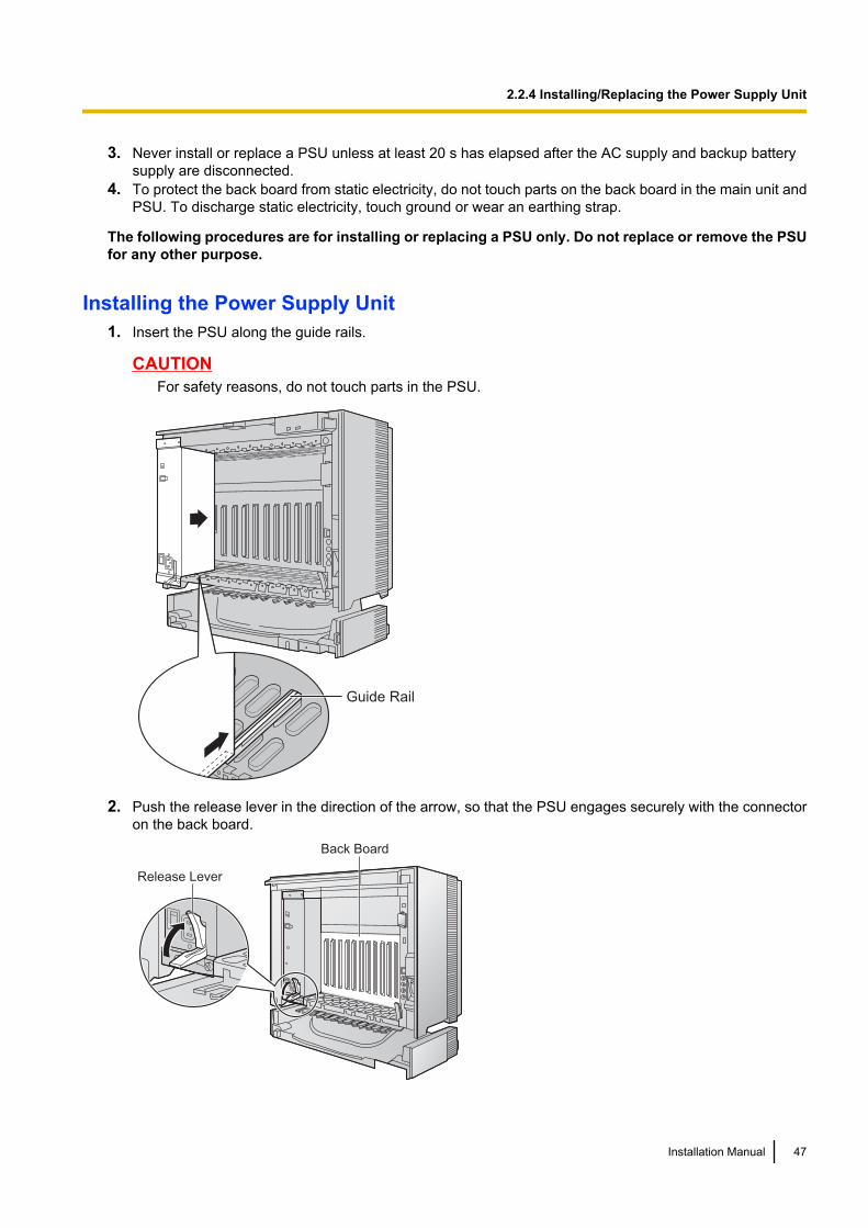
3. Never install or replace a PSU unless at least 20 s has elapsed after the AC supply and backup batterysupply are disconnected.
4. To protect the back board from static electricity, do not touch parts on the back board in the main unit andPSU. To discharge static electricity, touch ground or wear an earthing strap.
The following procedures are for installing or replacing a PSU only. Do not replace or remove the PSUfor any other purpose.
Installing the Power Supply Unit1. Insert the PSU along the guide rails.
CAUTIONFor safety reasons, do not touch parts in the PSU.
Guide Rail
2. Push the release lever in the direction of the arrow, so that the PSU engages securely with the connectoron the back board.
Release Lever
Back Board
Installation Manual 47
2.2.4 Installing/Replacing the Power Supply Unit
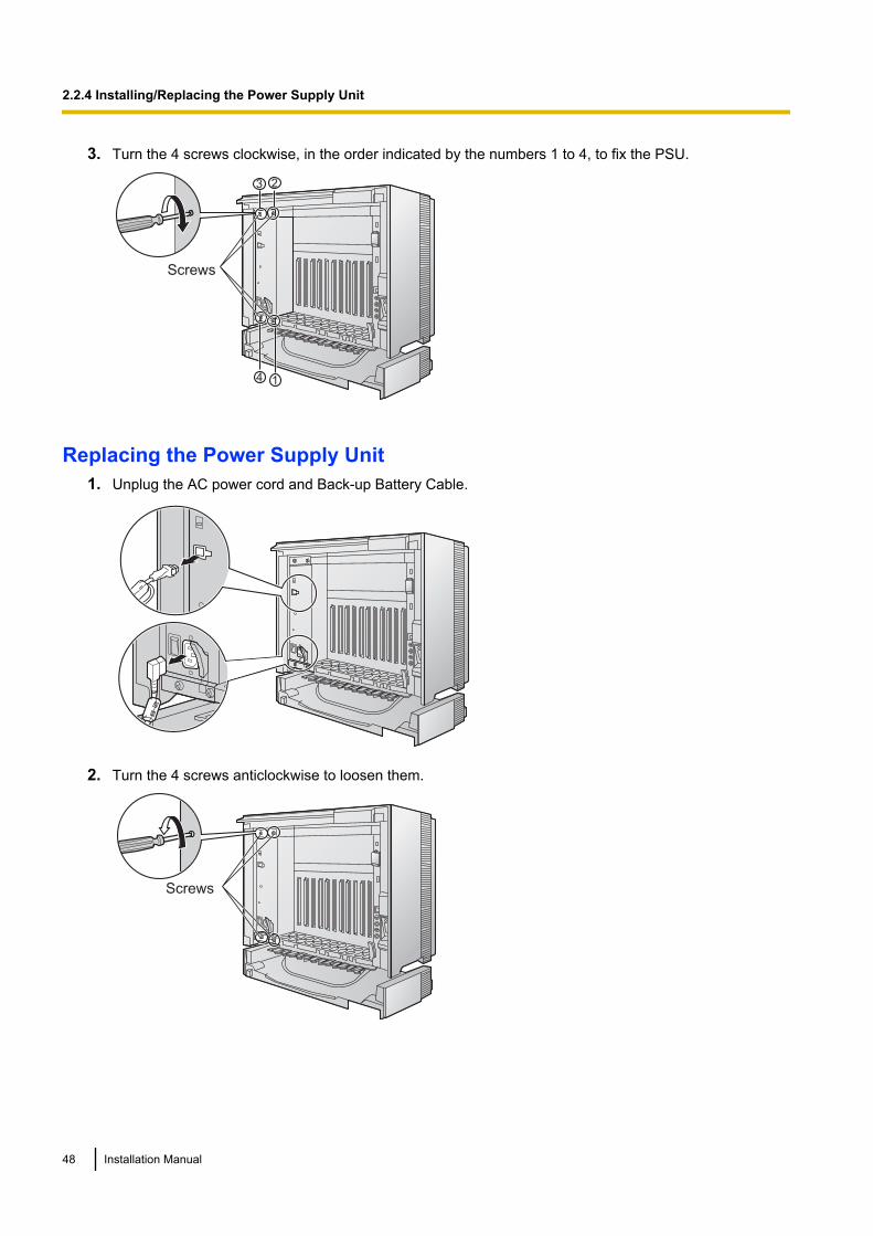
3. Turn the 4 screws clockwise, in the order indicated by the numbers 1 to 4, to fix the PSU.
Screws
1
3 2
4
Replacing the Power Supply Unit1. Unplug the AC power cord and Back-up Battery Cable.
2. Turn the 4 screws anticlockwise to loosen them.
Screws
48 Installation Manual
2.2.4 Installing/Replacing the Power Supply Unit
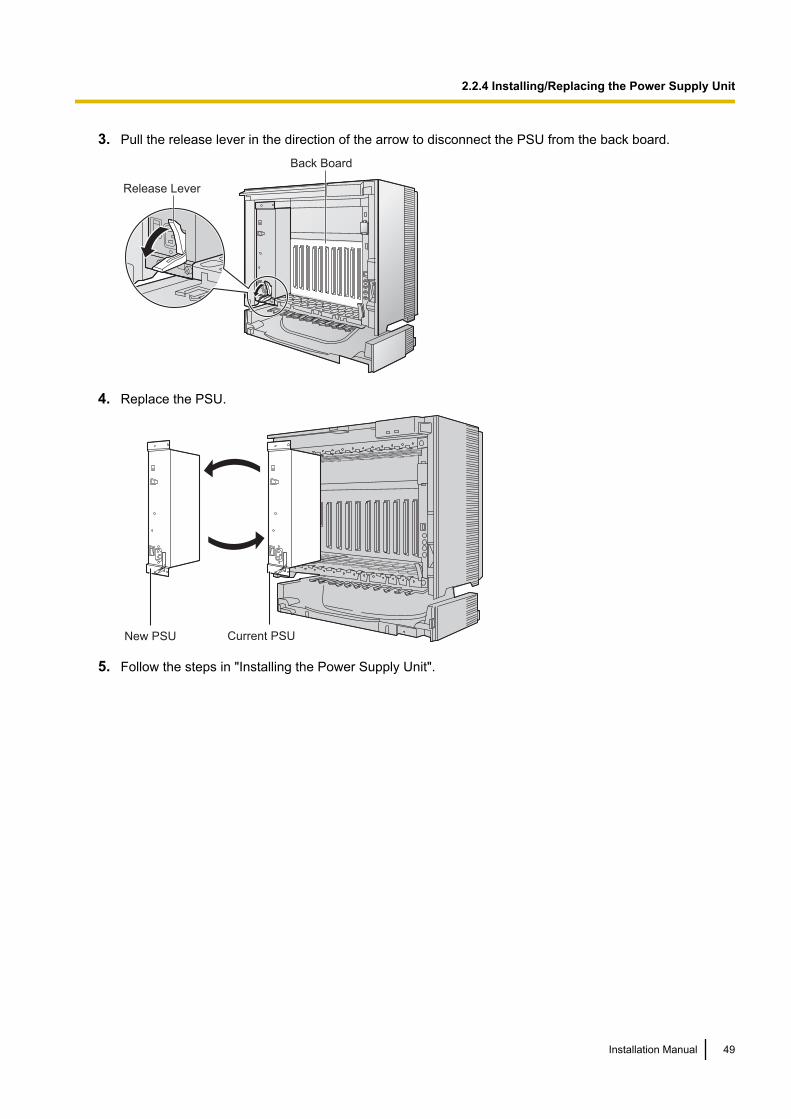
3. Pull the release lever in the direction of the arrow to disconnect the PSU from the back board.
Release Lever
Back Board
4. Replace the PSU.
Current PSUNew PSU
5. Follow the steps in "Installing the Power Supply Unit".
Installation Manual 49
2.2.4 Installing/Replacing the Power Supply Unit
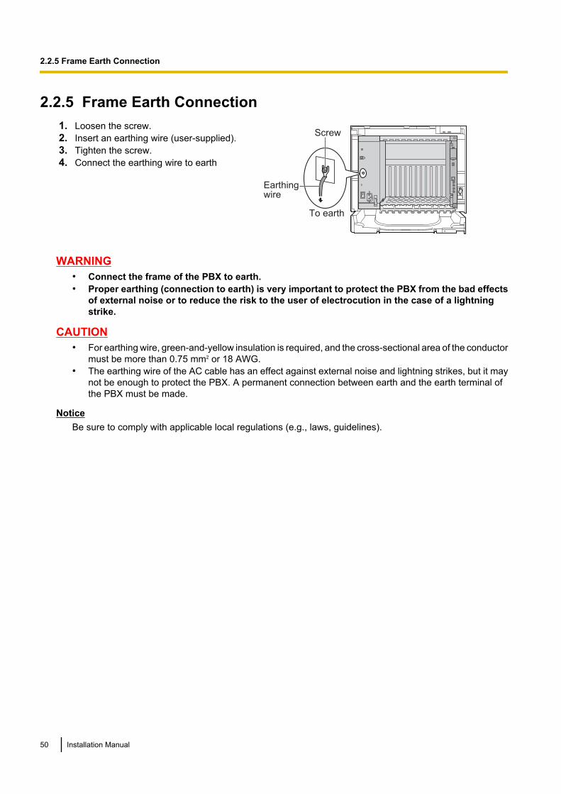
2.2.5 Frame Earth Connection1. Loosen the screw.2. Insert an earthing wire (user-supplied).3. Tighten the screw.4. Connect the earthing wire to earth
Screw
To earth
Earthing wire
WARNING• Connect the frame of the PBX to earth.• Proper earthing (connection to earth) is very important to protect the PBX from the bad effects
of external noise or to reduce the risk to the user of electrocution in the case of a lightningstrike.
CAUTION• For earthing wire, green-and-yellow insulation is required, and the cross-sectional area of the conductor
must be more than 0.75 mm2 or 18 AWG.• The earthing wire of the AC cable has an effect against external noise and lightning strikes, but it may
not be enough to protect the PBX. A permanent connection between earth and the earth terminal ofthe PBX must be made.
NoticeBe sure to comply with applicable local regulations (e.g., laws, guidelines).
50 Installation Manual
2.2.5 Frame Earth Connection
2.2.6 Backup Battery ConnectionThe backup batteries and Back-up Battery Cable provide a backup power supply to allow full use of the PBXin the event of a power failure. In case of power failure, the backup batteries automatically maintain the powerto the PBX without interruption.
User-supplied Items• Backup Batteries: VRLA (Valve Regulated Lead Acid) 12 V DC ´ 3• Back-up Battery Cable: KX-A228 (for PSU-S and PSU-M) or KX-A229 (for PSU-L)
WARNINGThere is a danger of explosion if backup batteries are incorrectly replaced. Replace only with thesame or equivalent type recommended by the battery manufacturer. Dispose of used batteriesaccording to the manufacturer's instructions.
CAUTION• Make sure that the Back-up Battery Cable is securely fastened to both the backup batteries and the
PBX.• Be sure to comply with applicable local regulations (e.g., laws, guidelines).• Make sure that the polarities of the backup batteries and wiring are correct.• Make sure that you do not short the backup batteries or cables.• Use the correct type of Back-up Battery Cable for the PSU.
Note• Turn on the battery switch on the PSU only after the installation of the PBX is finished and AC power
is available.• The recommended maximum capacity per shelf is 28 Ah, to maintain effective battery charge.• Make sure that the type and capacity of the 3 backup batteries are identical.• The Back-up Battery Cable should not be exposed to direct sunlight. Keep the Back-up Battery Cable
and the backup batteries away from heating appliances and fire. Place the backup batteries in aventilated place.
• For details about the backup batteries, refer to the manual for the batteries.
Backup Power Supply DurationThe length of time that backup batteries can power the PBX varies depending on the total load figure. For howto calculate the load figure from the connected items, refer to "Load Figure Calculation".
Examples
Battery Capacity Total Load Figure Backup Power Supply Duration*1
28 Ah
64 11 h
128 5.5 h
512 3 h
*1 The duration may vary depending on the conditions.
Connecting Backup Batteries1. Turn off the battery switch on the PSU.
Installation Manual 51
2.2.6 Backup Battery Connection
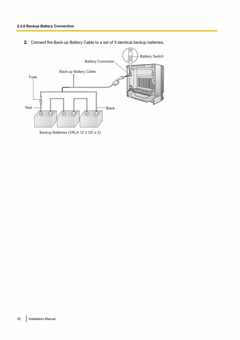
2. Connect the Back-up Battery Cable to a set of 3 identical backup batteries.
Back-up Battery Cable
Backup Batteries (VRLA 12 V DC x 3)
Red Black
Battery Connector
Battery Switch
ON
OFF
Fuse
52 Installation Manual
2.2.6 Backup Battery Connection
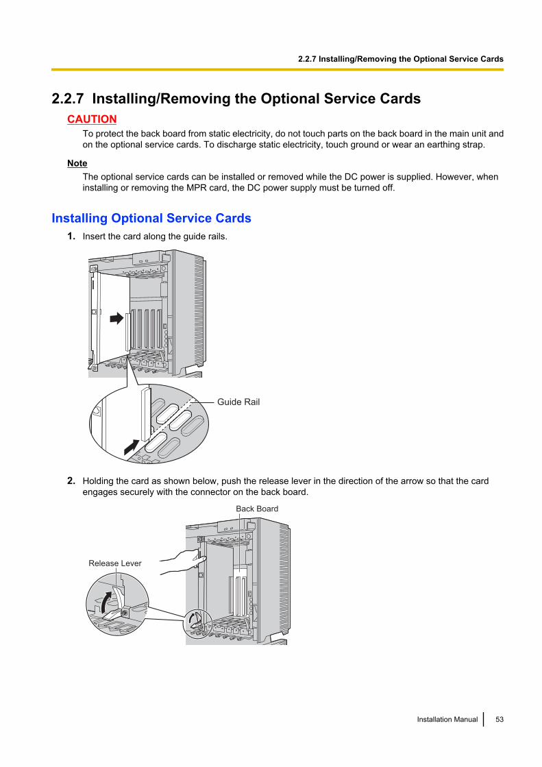
2.2.7 Installing/Removing the Optional Service CardsCAUTION
To protect the back board from static electricity, do not touch parts on the back board in the main unit andon the optional service cards. To discharge static electricity, touch ground or wear an earthing strap.
NoteThe optional service cards can be installed or removed while the DC power is supplied. However, wheninstalling or removing the MPR card, the DC power supply must be turned off.
Installing Optional Service Cards1. Insert the card along the guide rails.
Guide Rail
2. Holding the card as shown below, push the release lever in the direction of the arrow so that the cardengages securely with the connector on the back board.
Release Lever
Back Board
Installation Manual 53
2.2.7 Installing/Removing the Optional Service Cards
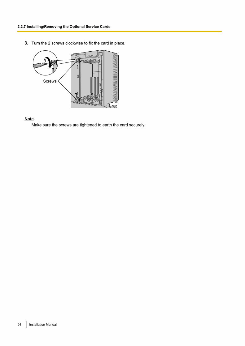
3. Turn the 2 screws clockwise to fix the card in place.
Screws
NoteMake sure the screws are tightened to earth the card securely.
54 Installation Manual
2.2.7 Installing/Removing the Optional Service Cards

Covering the Blank SlotsBe sure to cover each slot in which no optional service card is installed by using a Blank Slot Cover.
CAUTIONFailure to install the Blank Slot Cover may cause electromagnetic interference.
Installation Manual 55
2.2.7 Installing/Removing the Optional Service Cards
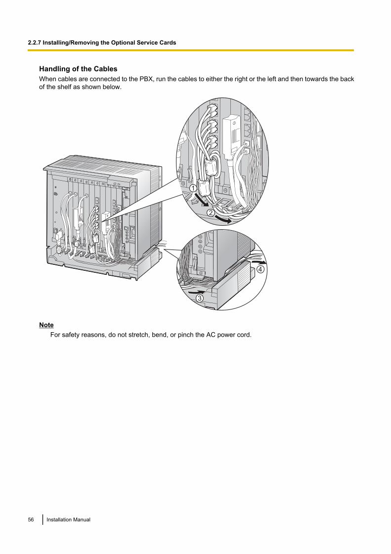
Handling of the CablesWhen cables are connected to the PBX, run the cables to either the right or the left and then towards the backof the shelf as shown below.
3
4
1
2
NoteFor safety reasons, do not stretch, bend, or pinch the AC power cord.
56 Installation Manual
2.2.7 Installing/Removing the Optional Service Cards
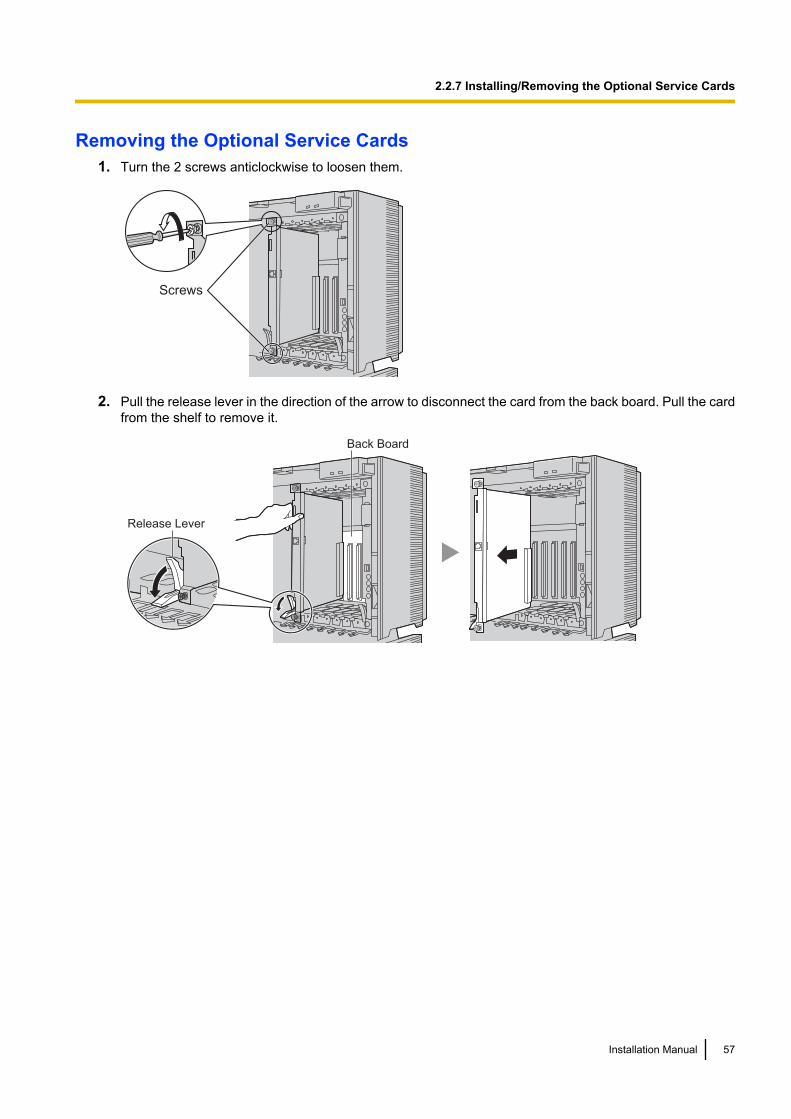
Removing the Optional Service Cards1. Turn the 2 screws anticlockwise to loosen them.
Screws
2. Pull the release lever in the direction of the arrow to disconnect the card from the back board. Pull the cardfrom the shelf to remove it.
Release Lever
Back Board
Installation Manual 57
2.2.7 Installing/Removing the Optional Service Cards
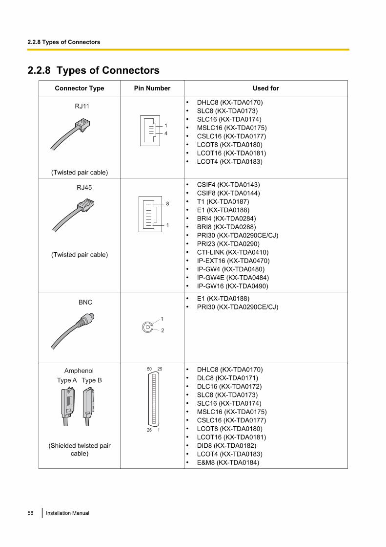
2.2.8 Types of ConnectorsConnector Type Pin Number Used for
RJ11
(Twisted pair cable)
1
4
• DHLC8 (KX-TDA0170)• SLC8 (KX-TDA0173)• SLC16 (KX-TDA0174)• MSLC16 (KX-TDA0175)• CSLC16 (KX-TDA0177)• LCOT8 (KX-TDA0180)• LCOT16 (KX-TDA0181)• LCOT4 (KX-TDA0183)
RJ45
(Twisted pair cable)
8
1
• CSIF4 (KX-TDA0143)• CSIF8 (KX-TDA0144)• T1 (KX-TDA0187)• E1 (KX-TDA0188)• BRI4 (KX-TDA0284)• BRI8 (KX-TDA0288)• PRI30 (KX-TDA0290CE/CJ)• PRI23 (KX-TDA0290)• CTI-LINK (KX-TDA0410)• IP-EXT16 (KX-TDA0470)• IP-GW4 (KX-TDA0480)• IP-GW4E (KX-TDA0484)• IP-GW16 (KX-TDA0490)
BNC
1
2
• E1 (KX-TDA0188)• PRI30 (KX-TDA0290CE/CJ)
Amphenol
Type A Type B
(Shielded twisted paircable)
50 25
26 1
• DHLC8 (KX-TDA0170)• DLC8 (KX-TDA0171)• DLC16 (KX-TDA0172)• SLC8 (KX-TDA0173)• SLC16 (KX-TDA0174)• MSLC16 (KX-TDA0175)• CSLC16 (KX-TDA0177)• LCOT8 (KX-TDA0180)• LCOT16 (KX-TDA0181)• DID8 (KX-TDA0182)• LCOT4 (KX-TDA0183)• E&M8 (KX-TDA0184)
58 Installation Manual
2.2.8 Types of Connectors
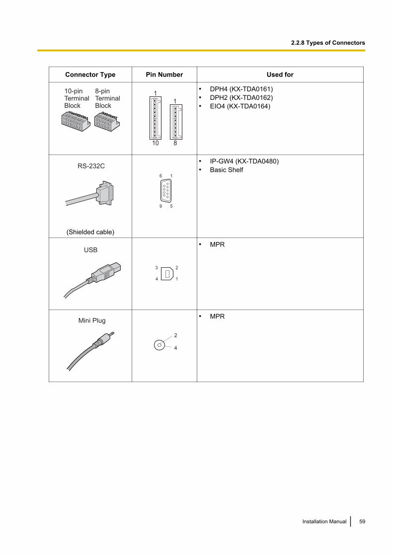
Connector Type Pin Number Used for
10-pinTerminalBlock
8-pinTerminalBlock
8
1
10
1• DPH4 (KX-TDA0161)• DPH2 (KX-TDA0162)• EIO4 (KX-TDA0164)
RS-232C
(Shielded cable)
9 5
6 1
• IP-GW4 (KX-TDA0480)• Basic Shelf
USB
2
1
3
4
• MPR
Mini Plug
2
4
• MPR
Installation Manual 59
2.2.8 Types of Connectors
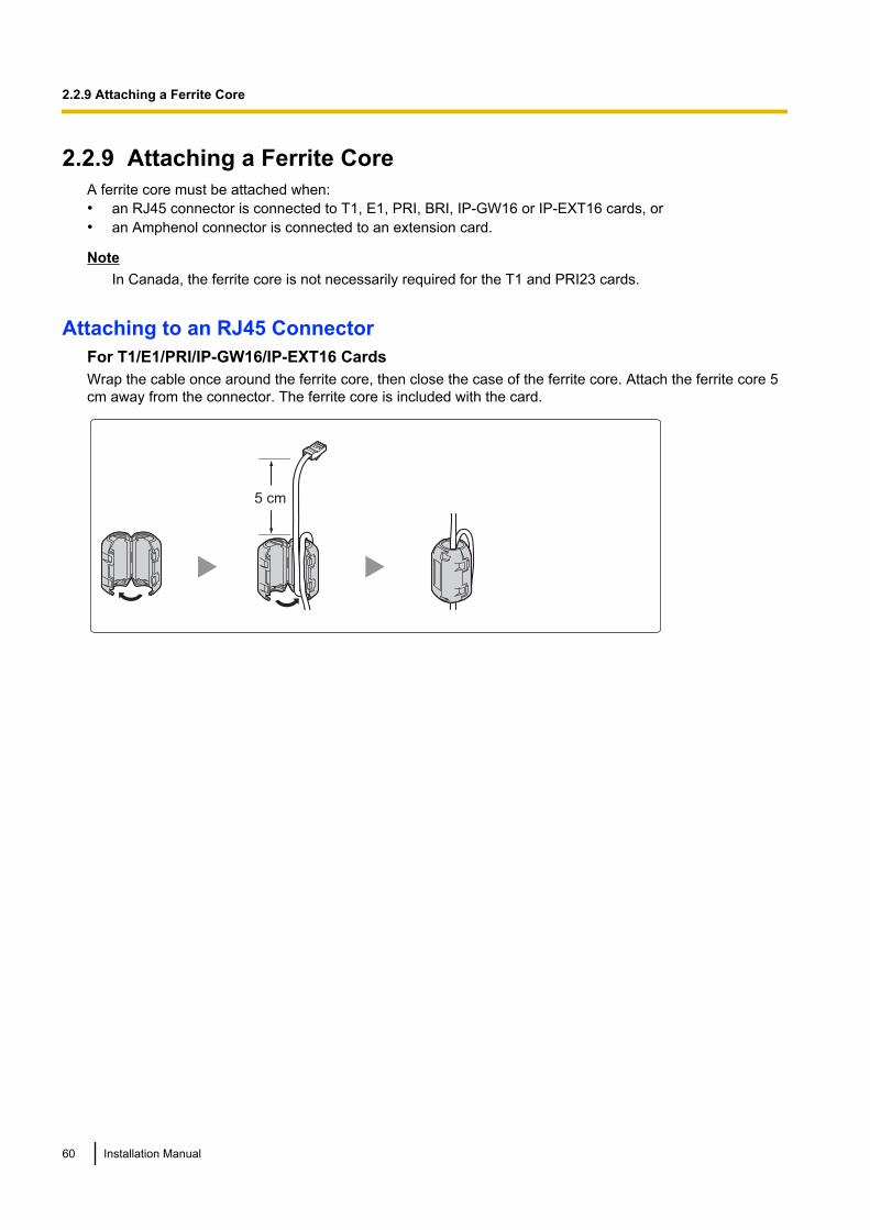
2.2.9 Attaching a Ferrite CoreA ferrite core must be attached when:• an RJ45 connector is connected to T1, E1, PRI, BRI, IP-GW16 or IP-EXT16 cards, or• an Amphenol connector is connected to an extension card.
NoteIn Canada, the ferrite core is not necessarily required for the T1 and PRI23 cards.
Attaching to an RJ45 ConnectorFor T1/E1/PRI/IP-GW16/IP-EXT16 CardsWrap the cable once around the ferrite core, then close the case of the ferrite core. Attach the ferrite core 5cm away from the connector. The ferrite core is included with the card.
5 cm
60 Installation Manual
2.2.9 Attaching a Ferrite Core
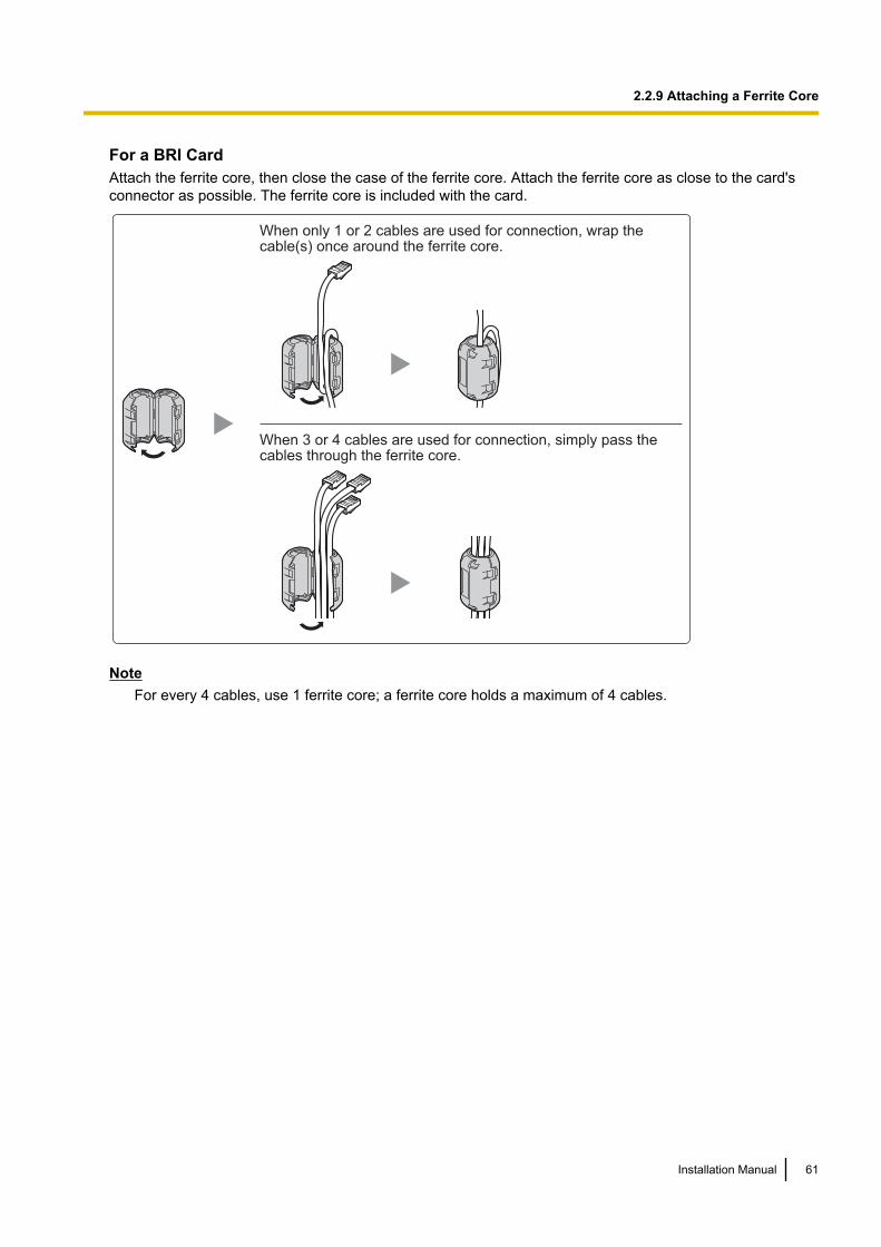
For a BRI CardAttach the ferrite core, then close the case of the ferrite core. Attach the ferrite core as close to the card'sconnector as possible. The ferrite core is included with the card.
When only 1 or 2 cables are used for connection, wrap the cable(s) once around the ferrite core.
When 3 or 4 cables are used for connection, simply pass the cables through the ferrite core.
NoteFor every 4 cables, use 1 ferrite core; a ferrite core holds a maximum of 4 cables.
Installation Manual 61
2.2.9 Attaching a Ferrite Core

Attaching to an Amphenol ConnectorFor Extension CardsPass the cable through the ferrite core, then close the case of the ferrite core. Attach the ferrite core 3 cm awayfrom the connector. The ferrite core is included with the card.
3 cm
If you need to open the ferrite core, use a flathead screwdriver to unlatch the case of the ferrite core.
62 Installation Manual
2.2.9 Attaching a Ferrite Core
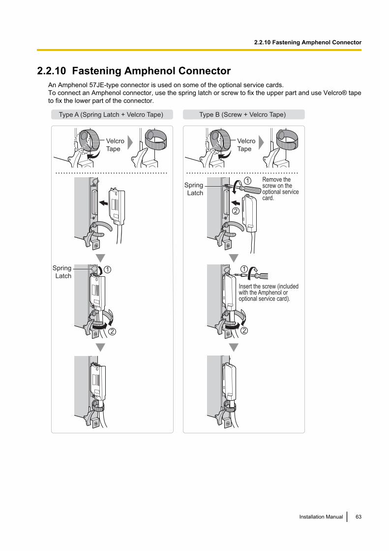
2.2.10 Fastening Amphenol ConnectorAn Amphenol 57JE-type connector is used on some of the optional service cards.To connect an Amphenol connector, use the spring latch or screw to fix the upper part and use Velcro® tapeto fix the lower part of the connector.
Type A (Spring Latch + Velcro Tape) Type B (Screw + Velcro Tape)
Velcro
Tape
Velcro
Tape
2
1
2
2
1Spring
Latch
1Spring
Latch
Remove the screw on the optional service card.
Insert the screw (included with the Amphenol or optional service card).
Installation Manual 63
2.2.10 Fastening Amphenol Connector

Amphenol Connector Pin Assignment ChartBelow is an Amphenol connector pin assignment chart for all optional service cards that use the Amphenolconnector. For more details, refer to the appropriate section in "2.4 Information about the TrunkCards" and "2.5 Information about the Extension Cards".
LCOT4
RA
TA
RB
TB
RC
TC
RD
TD
Pin No.
1
26
2
27
3
28
4
29
5
30
6
31
7
32
8
33
9
34
10
35
11
36
12
37
13
38
14
39
15
40
16
41
17
42
18
43
19
44
20
45
21
46
22
47
23
48
24
49
25
50
LCOT16
RA
TA
RB
TB
RC
TC
RD
TD
RE
TE
RF
TF
RG
TG
RH
TH
RI
TI
RJ
TJ
RK
TK
RL
TL
RM
TM
RN
TN
RO
TO
RP
TP
DID8
RA
TA
RB
TB
RC
TC
RD
TD
RE
TE
RF
TF
RG
TG
RH
TH
E&M8
TA
RA
T1A
R1A
EA
MA
SGA
SGB
TB
RB
T1B
R1B
EB
MB
TC
RC
T1C
R1C
EC
MC
TD
RD
T1D
R1D
ED
MD
TE
RE
T1E
R1E
EE
ME
TF
RF
T1F
R1F
EF
MF
TG
RG
T1G
R1G
EG
MG
TH
RH
T1H
R1H
EH
MH
DHLC8
RA
TA
D2A
D1A
RB
TB
D2B
D1B
RC
TC
D2C
D1C
RD
TD
D2D
D1D
RE
TE
D2E
D1E
RF
TF
D2F
D1F
RG
TG
D2G
D1G
RH
TH
D2H
D1H
DLC8
D2A
D1A
D2B
D1B
D2C
D1C
D2D
D1D
D2E
D1E
D2F
D1F
D2G
D1G
D2H
D1H
DLC16
D2A
D1A
D2B
D1B
D2C
D1C
D2D
D1D
D2E
D1E
D2F
D1F
D2G
D1G
D2H
D1H
D2I
D1I
D2J
D1J
D2K
D1K
D2L
D1L
D2M
D1M
D2N
D1N
D2O
D1O
D2P
D1P
MSLC16
RA
TA
RB
TB
RC
TC
RD
TD
RE
TE
RF
TF
RG
TG
RH
TH
RI
TI
RJ
TJ
RK
TK
RL
TL
RM
TM
RN
TN
RO
TO
RP
TP
CSLC16
RA
TA
RB
TB
RC
TC
RD
TD
RE
TE
RF
TF
RG
TG
RH
TH
RI
TI
RJ
TJ
RK
TK
RL
TL
RM
TM
RN
TN
RO
TO
RP
TP
SLC16
RA
TA
RB
TB
RC
TC
RD
TD
RE
TE
RF
TF
RG
TG
RH
TH
RI
TI
RJ
TJ
RK
TK
RL
TL
RM
TM
RN
TN
RO
TO
RP
TP
SLC8
RA
TA
RB
TB
RC
TC
RD
TD
RE
TE
RF
TF
RG
TG
RH
TH
LCOT8
RA
TA
RB
TB
RC
TC
RD
TD
RE
TE
RF
TF
RG
TG
RH
TH
64 Installation Manual
2.2.10 Fastening Amphenol Connector
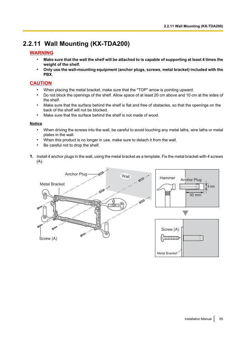
2.2.11 Wall Mounting (KX-TDA200)WARNING
• Make sure that the wall the shelf will be attached to is capable of supporting at least 4 times theweight of the shelf.
• Only use the wall-mounting equipment (anchor plugs, screws, metal bracket) included with thePBX.
CAUTION• When placing the metal bracket, make sure that the "TOP" arrow is pointing upward.• Do not block the openings of the shelf. Allow space of at least 20 cm above and 10 cm at the sides of
the shelf.• Make sure that the surface behind the shelf is flat and free of obstacles, so that the openings on the
back of the shelf will not be blocked.• Make sure that the surface behind the shelf is not made of wood.
Notice• When driving the screws into the wall, be careful to avoid touching any metal laths, wire laths or metal
plates in the wall.• When this product is no longer in use, make sure to detach it from the wall.• Be careful not to drop the shelf.
1. Install 4 anchor plugs in the wall, using the metal bracket as a template. Fix the metal bracket with 4 screws(A).
30 mm
8 mm
Anchor Plug
Metal Bracket
Wall
Screw (A)
Screw (A)
Metal Bracket
Hammer Anchor Plug
Installation Manual 65
2.2.11 Wall Mounting (KX-TDA200)
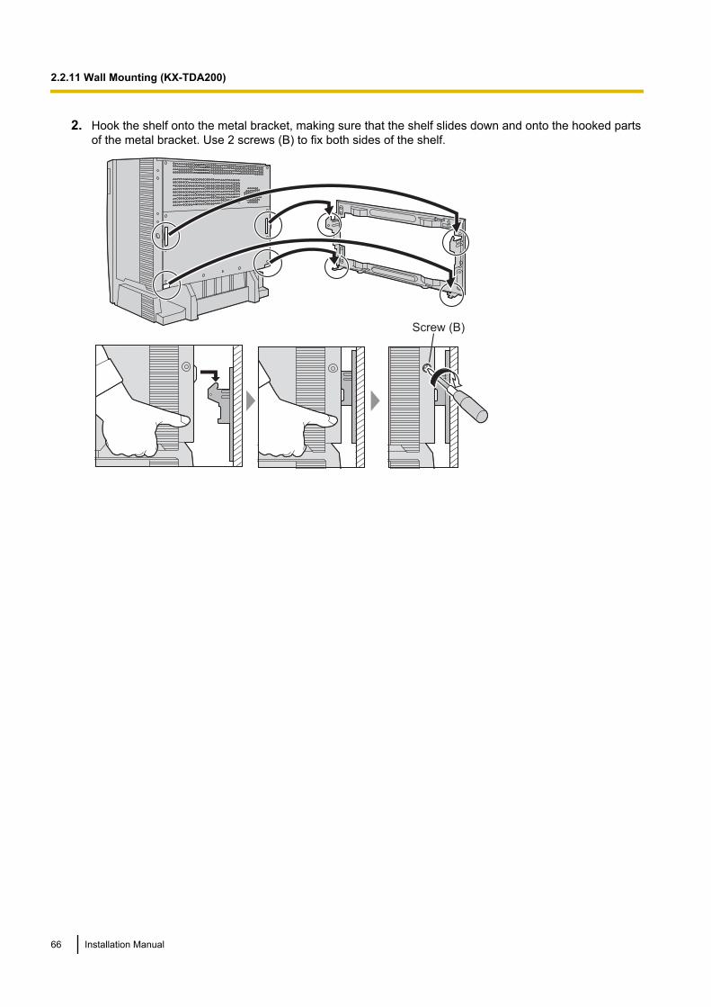
2. Hook the shelf onto the metal bracket, making sure that the shelf slides down and onto the hooked partsof the metal bracket. Use 2 screws (B) to fix both sides of the shelf.
TOP
Screw (B)
66 Installation Manual
2.2.11 Wall Mounting (KX-TDA200)
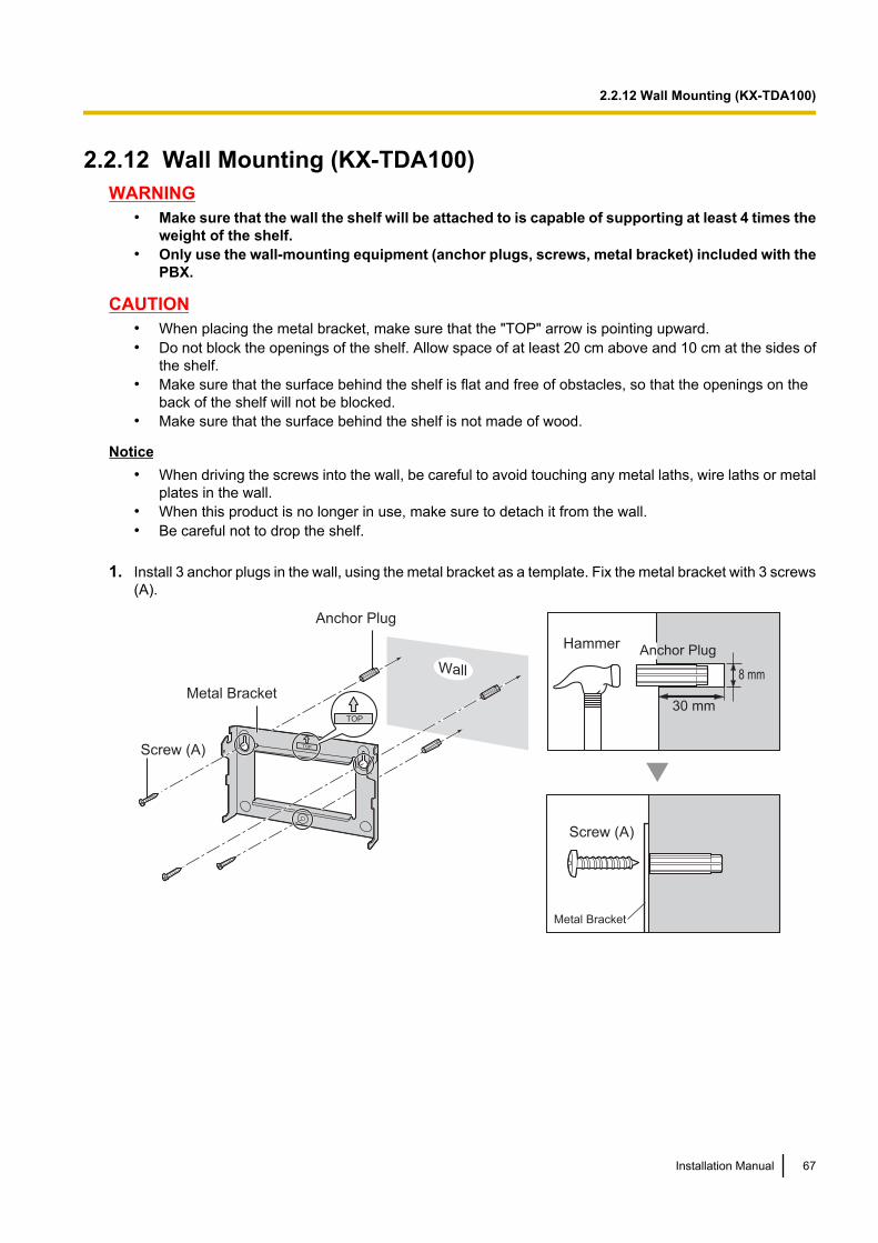
2.2.12 Wall Mounting (KX-TDA100)WARNING
• Make sure that the wall the shelf will be attached to is capable of supporting at least 4 times theweight of the shelf.
• Only use the wall-mounting equipment (anchor plugs, screws, metal bracket) included with thePBX.
CAUTION• When placing the metal bracket, make sure that the "TOP" arrow is pointing upward.• Do not block the openings of the shelf. Allow space of at least 20 cm above and 10 cm at the sides of
the shelf.• Make sure that the surface behind the shelf is flat and free of obstacles, so that the openings on the
back of the shelf will not be blocked.• Make sure that the surface behind the shelf is not made of wood.
Notice• When driving the screws into the wall, be careful to avoid touching any metal laths, wire laths or metal
plates in the wall.• When this product is no longer in use, make sure to detach it from the wall.• Be careful not to drop the shelf.
1. Install 3 anchor plugs in the wall, using the metal bracket as a template. Fix the metal bracket with 3 screws(A).
TOP
30 mm
8 mm
TOP
Metal Bracket
Screw (A)
Anchor Plug
Screw (A)
Metal Bracket
Hammer Anchor Plug
Wall
Installation Manual 67
2.2.12 Wall Mounting (KX-TDA100)
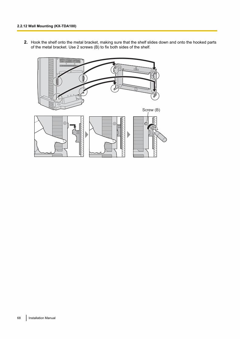
2. Hook the shelf onto the metal bracket, making sure that the shelf slides down and onto the hooked partsof the metal bracket. Use 2 screws (B) to fix both sides of the shelf.
TOP
Screw (B)
68 Installation Manual
2.2.12 Wall Mounting (KX-TDA100)
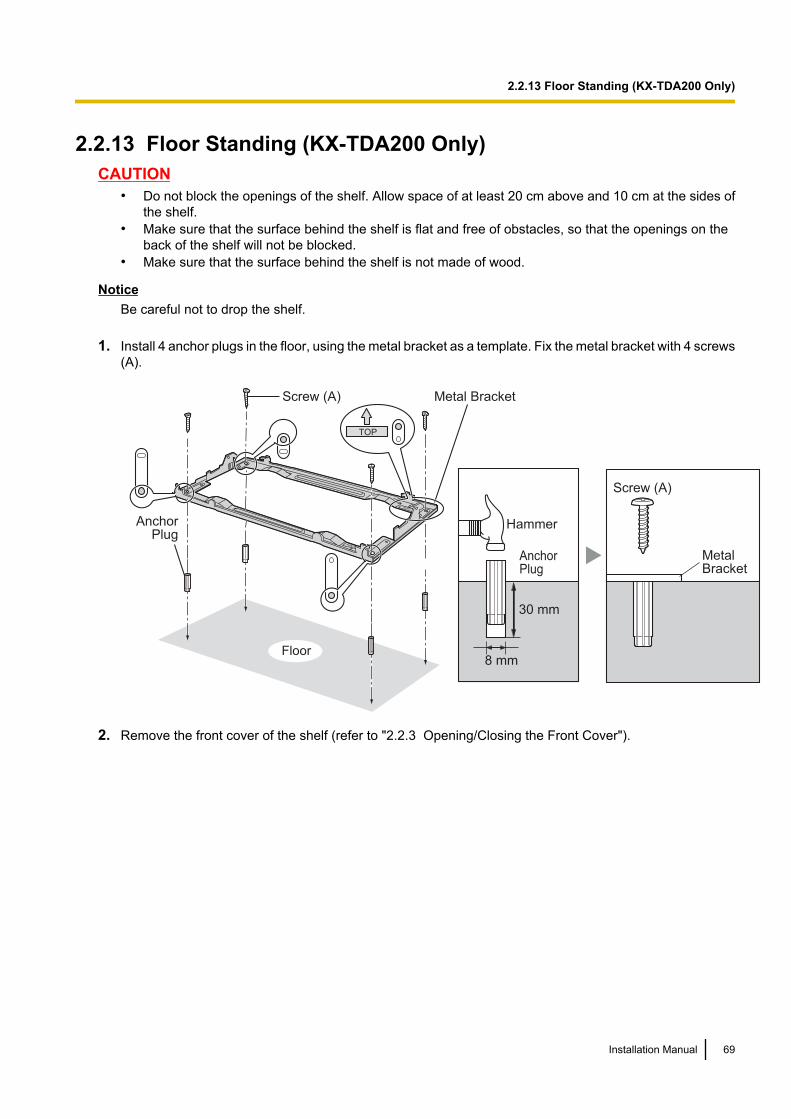
2.2.13 Floor Standing (KX-TDA200 Only)CAUTION
• Do not block the openings of the shelf. Allow space of at least 20 cm above and 10 cm at the sides ofthe shelf.
• Make sure that the surface behind the shelf is flat and free of obstacles, so that the openings on theback of the shelf will not be blocked.
• Make sure that the surface behind the shelf is not made of wood.
NoticeBe careful not to drop the shelf.
1. Install 4 anchor plugs in the floor, using the metal bracket as a template. Fix the metal bracket with 4 screws(A).
TOP
30 mm
8 mmFloor
Screw (A) Metal Bracket
AnchorPlug
AnchorPlug
Hammer
MetalBracket
Screw (A)
2. Remove the front cover of the shelf (refer to "2.2.3 Opening/Closing the Front Cover").
Installation Manual 69
2.2.13 Floor Standing (KX-TDA200 Only)
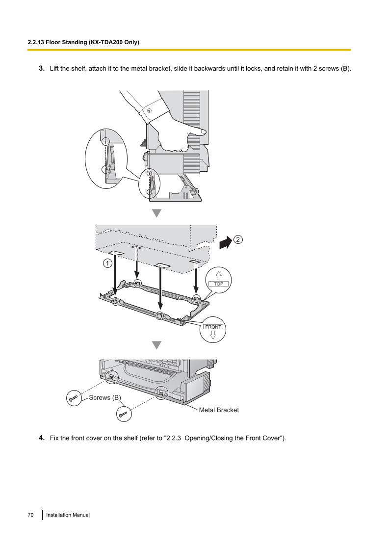
3. Lift the shelf, attach it to the metal bracket, slide it backwards until it locks, and retain it with 2 screws (B).
Screws (B)
Metal Bracket
FRONT
TOP
1
2
4. Fix the front cover on the shelf (refer to "2.2.3 Opening/Closing the Front Cover").
70 Installation Manual
2.2.13 Floor Standing (KX-TDA200 Only)

2.2.14 Surge Protector InstallationOverview
A massive electrical surge can be caused if lightning strikes a telephone cable 10 m above ground, or if atelephone line comes into contact with a power line. A surge protector is a device that is connected to a trunkto prevent potentially dangerous electrical surges from entering the building via the trunk and damaging thePBX and connected equipment.
To protect the system from electrical surges, we strongly recommend connecting the system to a surgeprotector that meets the following specifications:– Surge arrestor type: 3-electrode arrestor– DC spark-over voltage: 230 V– Maximum peak current: at least 10 kAAdditionally, proper earthing is very important for the protection of the system (refer to "2.2.5 Frame EarthConnection").
Many countries/areas have regulations requiring surge protection. Be sure to comply with all applicable laws,regulations, and guidelines.
InstallationTrunk TrunkTrunk
Earth
Surge
Protector
Extn.
Extn.
Extn.: Extension line
SLT
PT
PT-interface CSCS
PBX
Frame
Earth
Terminal
Board
Installation Manual 71
2.2.14 Surge Protector Installation
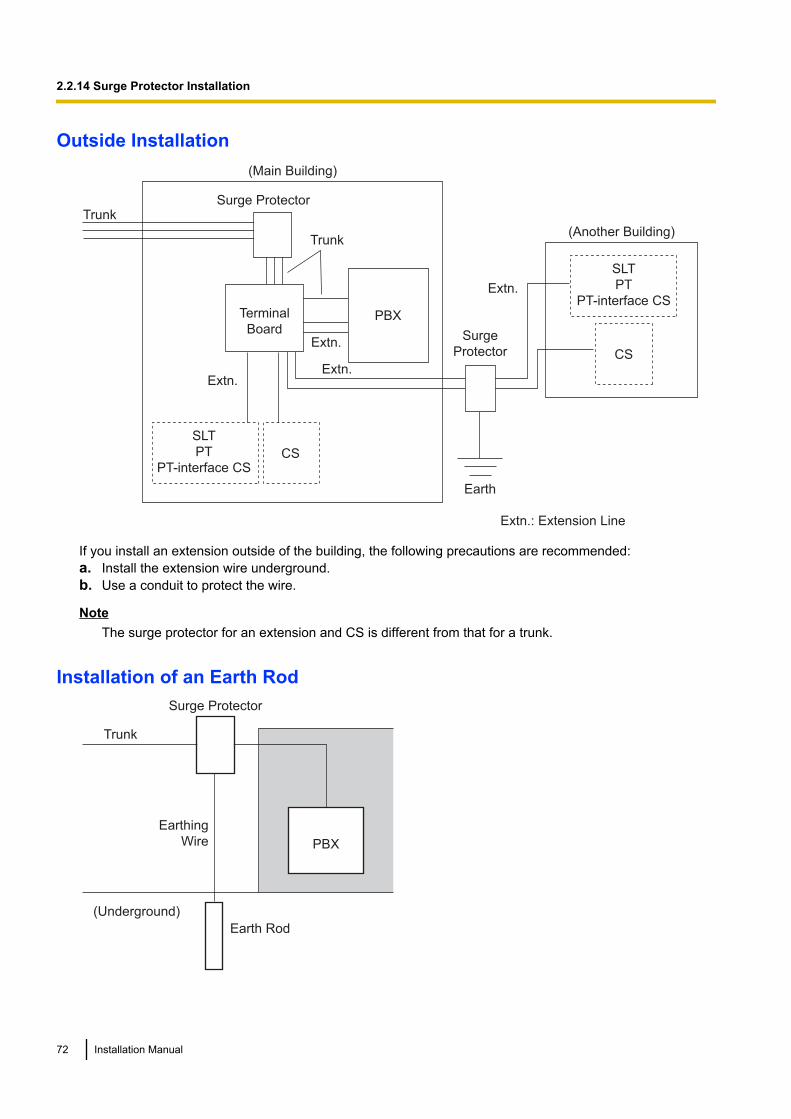
Outside Installation
Trunk
Extn.
Trunk
Surge Protector
Terminal
BoardSurge
Protector
PBX
(Main Building)
(Another Building)
Extn.: Extension Line
Extn.
Extn.
Earth
Extn.
SLT
PT
PT-interface CSCS
CS
SLT
PT
PT-interface CS
If you install an extension outside of the building, the following precautions are recommended:a. Install the extension wire underground.b. Use a conduit to protect the wire.
NoteThe surge protector for an extension and CS is different from that for a trunk.
Installation of an Earth Rod
Trunk
PBX
Earthing
Wire
Earth Rod
(Underground)
Surge Protector
72 Installation Manual
2.2.14 Surge Protector Installation
1. Connect the earth rod to the surge protector using an earthing wire with a cross-sectional area of at least1.3 mm2.
2. Bury the earth rod near the protector. The earthing wire should be as short as possible.3. The earthing wire should run straight to the earth rod. Do not run the wire around other objects.4. Bury the earth rod at least 50 cm underground.
Note• The above figures are recommendations only.• The length of earth rod and the required depth depend on the composition of the soil.
Installation Manual 73
2.2.14 Surge Protector Installation
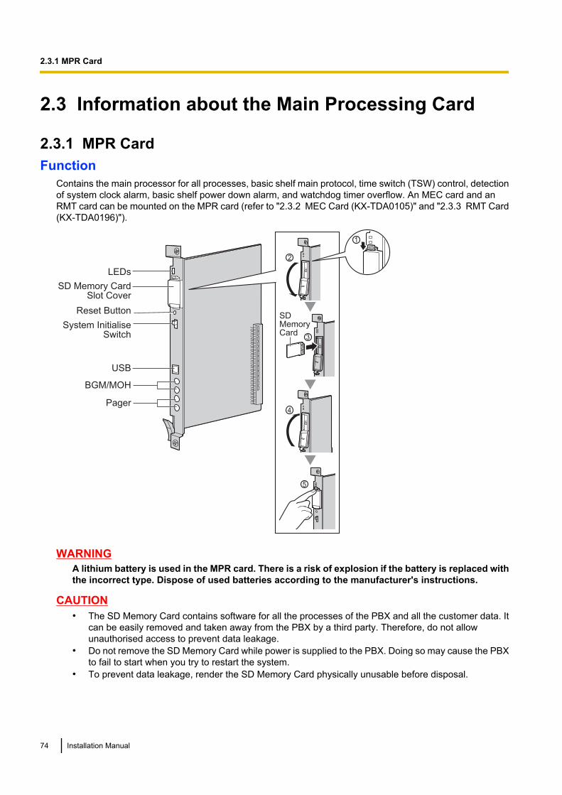
2.3 Information about the Main Processing Card
2.3.1 MPR CardFunction
Contains the main processor for all processes, basic shelf main protocol, time switch (TSW) control, detectionof system clock alarm, basic shelf power down alarm, and watchdog timer overflow. An MEC card and anRMT card can be mounted on the MPR card (refer to "2.3.2 MEC Card (KX-TDA0105)" and "2.3.3 RMT Card(KX-TDA0196)").
LEDs
Reset Button
SD Memory CardSlot Cover
System InitialiseSwitch
USB
BGM/MOH
Pager
SDCARD
2
SDCARD
4
5
SDCARD
SDMemoryCard
3
1
WARNINGA lithium battery is used in the MPR card. There is a risk of explosion if the battery is replaced withthe incorrect type. Dispose of used batteries according to the manufacturer's instructions.
CAUTION• The SD Memory Card contains software for all the processes of the PBX and all the customer data. It
can be easily removed and taken away from the PBX by a third party. Therefore, do not allowunauthorised access to prevent data leakage.
• Do not remove the SD Memory Card while power is supplied to the PBX. Doing so may cause the PBXto fail to start when you try to restart the system.
• To prevent data leakage, render the SD Memory Card physically unusable before disposal.
74 Installation Manual
2.3.1 MPR Card
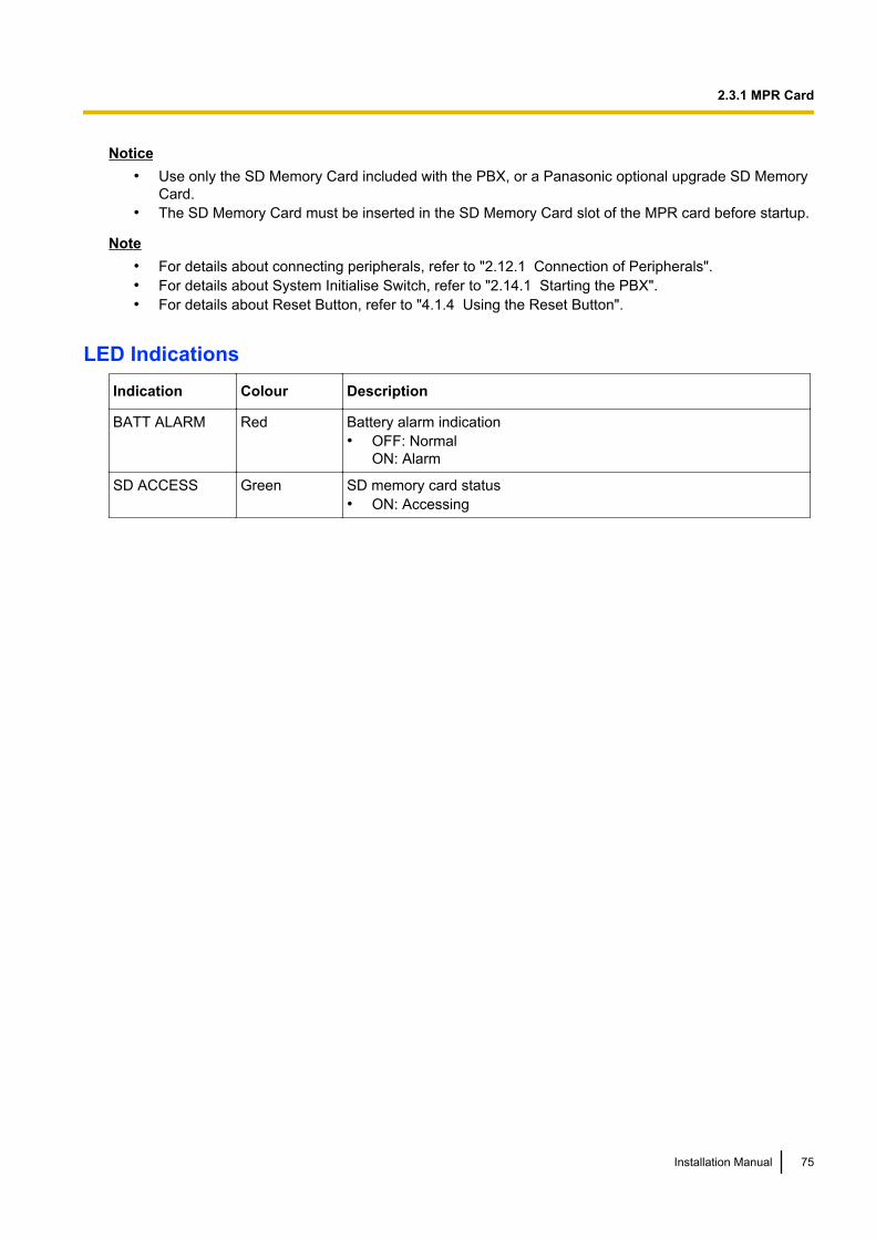
Notice• Use only the SD Memory Card included with the PBX, or a Panasonic optional upgrade SD Memory
Card.• The SD Memory Card must be inserted in the SD Memory Card slot of the MPR card before startup.
Note• For details about connecting peripherals, refer to "2.12.1 Connection of Peripherals".• For details about System Initialise Switch, refer to "2.14.1 Starting the PBX".• For details about Reset Button, refer to "4.1.4 Using the Reset Button".
LED IndicationsIndication Colour Description
BATT ALARM Red Battery alarm indication• OFF: Normal
ON: Alarm
SD ACCESS Green SD memory card status• ON: Accessing
Installation Manual 75
2.3.1 MPR Card
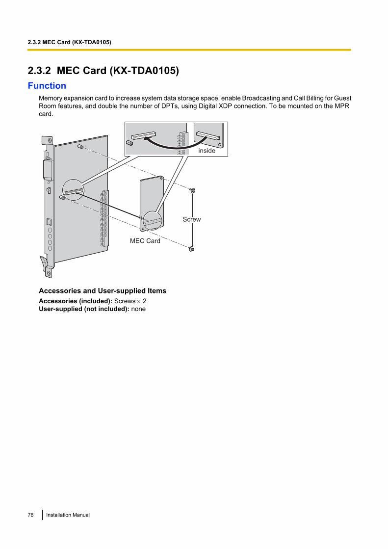
2.3.2 MEC Card (KX-TDA0105)Function
Memory expansion card to increase system data storage space, enable Broadcasting and Call Billing for GuestRoom features, and double the number of DPTs, using Digital XDP connection. To be mounted on the MPRcard.
MEC Card
Screw
inside
Accessories and User-supplied ItemsAccessories (included): Screws ´ 2User-supplied (not included): none
76 Installation Manual
2.3.2 MEC Card (KX-TDA0105)
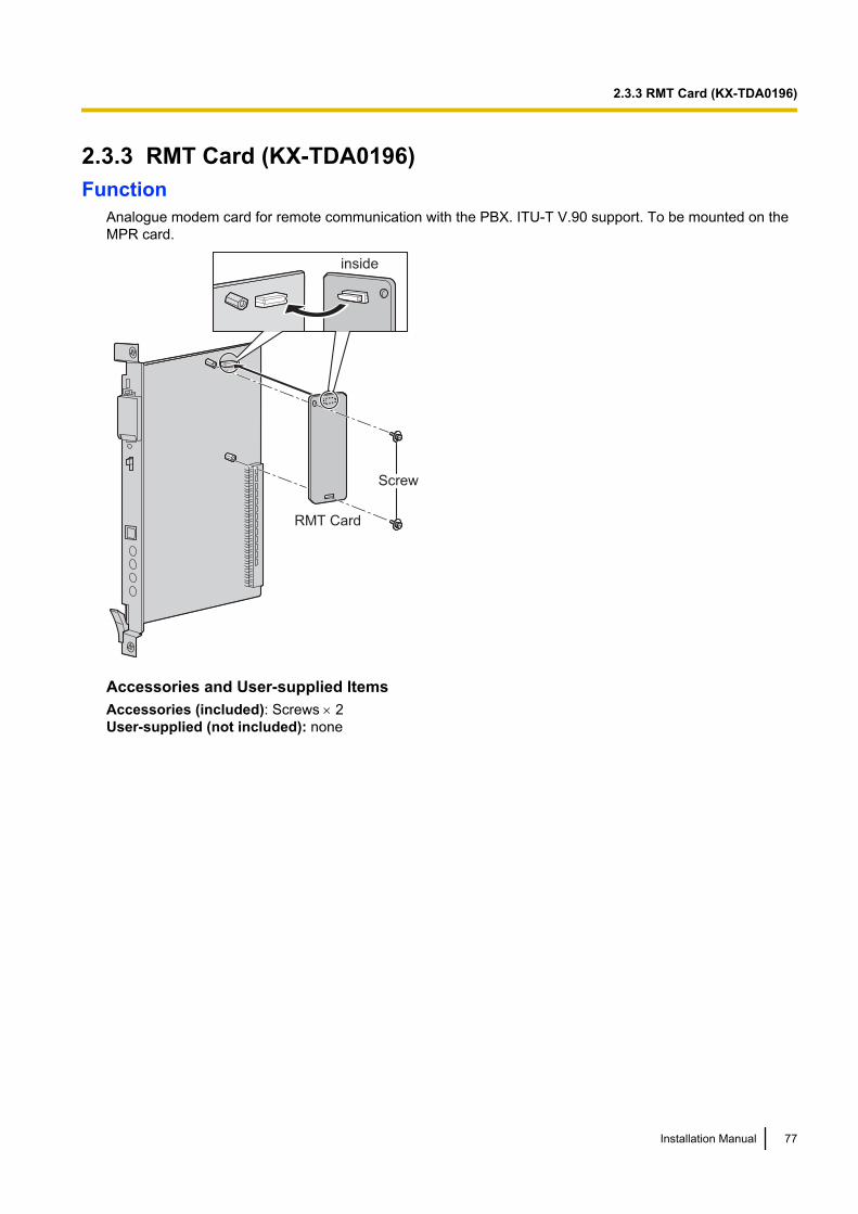
2.3.3 RMT Card (KX-TDA0196)Function
Analogue modem card for remote communication with the PBX. ITU-T V.90 support. To be mounted on theMPR card.
RMT Card
Screw
inside
Accessories and User-supplied ItemsAccessories (included): Screws ´ 2User-supplied (not included): none
Installation Manual 77
2.3.3 RMT Card (KX-TDA0196)
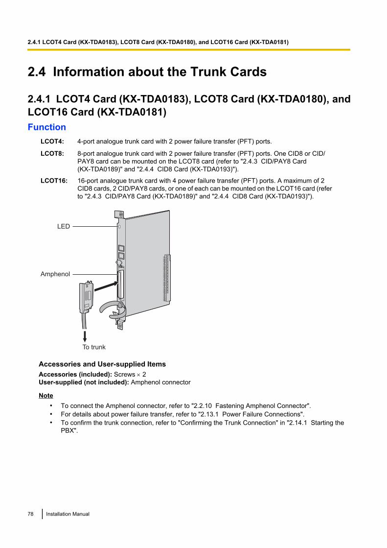
2.4 Information about the Trunk Cards
2.4.1 LCOT4 Card (KX-TDA0183), LCOT8 Card (KX-TDA0180), andLCOT16 Card (KX-TDA0181)Function
LCOT4: 4-port analogue trunk card with 2 power failure transfer (PFT) ports.
LCOT8: 8-port analogue trunk card with 2 power failure transfer (PFT) ports. One CID8 or CID/PAY8 card can be mounted on the LCOT8 card (refer to "2.4.3 CID/PAY8 Card(KX-TDA0189)" and "2.4.4 CID8 Card (KX-TDA0193)").
LCOT16: 16-port analogue trunk card with 4 power failure transfer (PFT) ports. A maximum of 2CID8 cards, 2 CID/PAY8 cards, or one of each can be mounted on the LCOT16 card (referto "2.4.3 CID/PAY8 Card (KX-TDA0189)" and "2.4.4 CID8 Card (KX-TDA0193)").
Amphenol
To trunk
LED
Accessories and User-supplied ItemsAccessories (included): Screws ´ 2User-supplied (not included): Amphenol connector
Note• To connect the Amphenol connector, refer to "2.2.10 Fastening Amphenol Connector".• For details about power failure transfer, refer to "2.13.1 Power Failure Connections".• To confirm the trunk connection, refer to "Confirming the Trunk Connection" in "2.14.1 Starting the
PBX".
78 Installation Manual
2.4.1 LCOT4 Card (KX-TDA0183), LCOT8 Card (KX-TDA0180), and LCOT16 Card (KX-TDA0181)
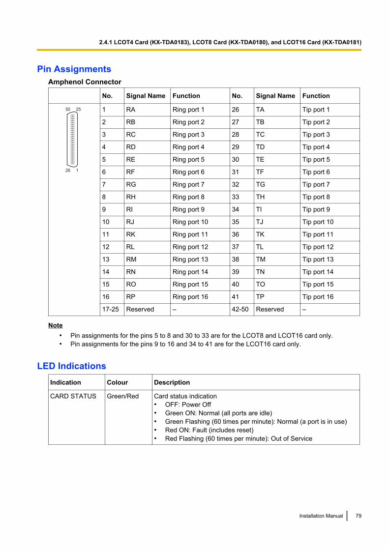
Pin AssignmentsAmphenol Connector
No. Signal Name Function No. Signal Name Function
50 25
26 1
1 RA Ring port 1 26 TA Tip port 1
2 RB Ring port 2 27 TB Tip port 2
3 RC Ring port 3 28 TC Tip port 3
4 RD Ring port 4 29 TD Tip port 4
5 RE Ring port 5 30 TE Tip port 5
6 RF Ring port 6 31 TF Tip port 6
7 RG Ring port 7 32 TG Tip port 7
8 RH Ring port 8 33 TH Tip port 8
9 RI Ring port 9 34 TI Tip port 9
10 RJ Ring port 10 35 TJ Tip port 10
11 RK Ring port 11 36 TK Tip port 11
12 RL Ring port 12 37 TL Tip port 12
13 RM Ring port 13 38 TM Tip port 13
14 RN Ring port 14 39 TN Tip port 14
15 RO Ring port 15 40 TO Tip port 15
16 RP Ring port 16 41 TP Tip port 16
17-25 Reserved – 42-50 Reserved –
Note• Pin assignments for the pins 5 to 8 and 30 to 33 are for the LCOT8 and LCOT16 card only.• Pin assignments for the pins 9 to 16 and 34 to 41 are for the LCOT16 card only.
LED IndicationsIndication Colour Description
CARD STATUS Green/Red Card status indication• OFF: Power Off• Green ON: Normal (all ports are idle)• Green Flashing (60 times per minute): Normal (a port is in use)• Red ON: Fault (includes reset)• Red Flashing (60 times per minute): Out of Service
Installation Manual 79
2.4.1 LCOT4 Card (KX-TDA0183), LCOT8 Card (KX-TDA0180), and LCOT16 Card (KX-TDA0181)
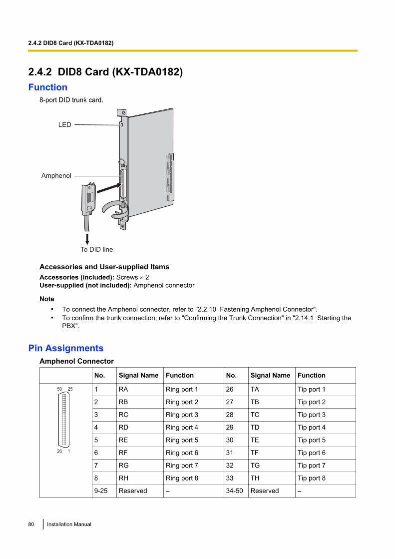
2.4.2 DID8 Card (KX-TDA0182)Function
8-port DID trunk card.
To DID line
LED
Amphenol
Accessories and User-supplied ItemsAccessories (included): Screws ´ 2User-supplied (not included): Amphenol connector
Note• To connect the Amphenol connector, refer to "2.2.10 Fastening Amphenol Connector".• To confirm the trunk connection, refer to "Confirming the Trunk Connection" in "2.14.1 Starting the
PBX".
Pin AssignmentsAmphenol Connector
No. Signal Name Function No. Signal Name Function
50 25
26 1
1 RA Ring port 1 26 TA Tip port 1
2 RB Ring port 2 27 TB Tip port 2
3 RC Ring port 3 28 TC Tip port 3
4 RD Ring port 4 29 TD Tip port 4
5 RE Ring port 5 30 TE Tip port 5
6 RF Ring port 6 31 TF Tip port 6
7 RG Ring port 7 32 TG Tip port 7
8 RH Ring port 8 33 TH Tip port 8
9-25 Reserved – 34-50 Reserved –
80 Installation Manual
2.4.2 DID8 Card (KX-TDA0182)

LED IndicationsIndication Colour Description
CARD STATUS Green/Red Card status indication• OFF: Power Off• Green ON: Normal (all ports are idle)• Green Flashing (60 times per minute): Normal (a port is in use)• Red ON: Fault (includes reset)• Red Flashing (60 times per minute): Out of Service
Installation Manual 81
2.4.2 DID8 Card (KX-TDA0182)
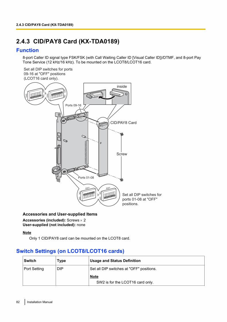
2.4.3 CID/PAY8 Card (KX-TDA0189)Function
8-port Caller ID signal type FSK/FSK (with Call Waiting Caller ID [Visual Caller ID])/DTMF, and 8-port PayTone Service (12 kHz/16 kHz). To be mounted on the LCOT8/LCOT16 card.
CID/PAY8 Card
inside
Screw
Set all DIP switches for
ports 01-08 at "OFF"
positions.
Set all DIP switches for ports
09-16 at "OFF" positions
(LCOT16 card only).
OF
F
ON
OF
F
ON
ON
O
FF
ON
O
FF
SW
2
SW
2
Ports 09-16
Ports 01-08
SW1 SW1
Accessories and User-supplied ItemsAccessories (included): Screws ´ 2User-supplied (not included): none
NoteOnly 1 CID/PAY8 card can be mounted on the LCOT8 card.
Switch Settings (on LCOT8/LCOT16 cards)Switch Type Usage and Status Definition
Port Setting DIP Set all DIP switches at "OFF" positions.
NoteSW2 is for the LCOT16 card only.
82 Installation Manual
2.4.3 CID/PAY8 Card (KX-TDA0189)
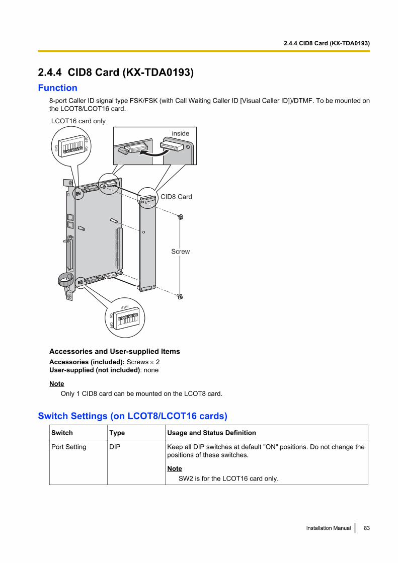
2.4.4 CID8 Card (KX-TDA0193)Function
8-port Caller ID signal type FSK/FSK (with Call Waiting Caller ID [Visual Caller ID])/DTMF. To be mounted onthe LCOT8/LCOT16 card.
CID8 Card
inside
Screw
OF
F
ON
ON
O
FF
SW
2
LCOT16 card only
SW1
Accessories and User-supplied ItemsAccessories (included): Screws ´ 2User-supplied (not included): none
NoteOnly 1 CID8 card can be mounted on the LCOT8 card.
Switch Settings (on LCOT8/LCOT16 cards)Switch Type Usage and Status Definition
Port Setting DIP Keep all DIP switches at default "ON" positions. Do not change thepositions of these switches.
NoteSW2 is for the LCOT16 card only.
Installation Manual 83
2.4.4 CID8 Card (KX-TDA0193)
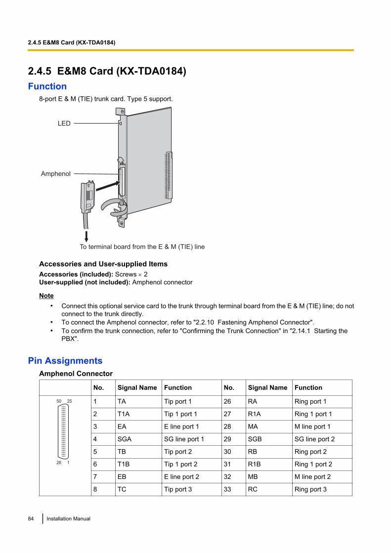
2.4.5 E&M8 Card (KX-TDA0184)Function
8-port E & M (TIE) trunk card. Type 5 support.
To terminal board from the E & M (TIE) line
LED
Amphenol
Accessories and User-supplied ItemsAccessories (included): Screws ´ 2User-supplied (not included): Amphenol connector
Note• Connect this optional service card to the trunk through terminal board from the E & M (TIE) line; do not
connect to the trunk directly.• To connect the Amphenol connector, refer to "2.2.10 Fastening Amphenol Connector".• To confirm the trunk connection, refer to "Confirming the Trunk Connection" in "2.14.1 Starting the
PBX".
Pin AssignmentsAmphenol Connector
No. Signal Name Function No. Signal Name Function
50 25
26 1
1 TA Tip port 1 26 RA Ring port 1
2 T1A Tip 1 port 1 27 R1A Ring 1 port 1
3 EA E line port 1 28 MA M line port 1
4 SGA SG line port 1 29 SGB SG line port 2
5 TB Tip port 2 30 RB Ring port 2
6 T1B Tip 1 port 2 31 R1B Ring 1 port 2
7 EB E line port 2 32 MB M line port 2
8 TC Tip port 3 33 RC Ring port 3
84 Installation Manual
2.4.5 E&M8 Card (KX-TDA0184)
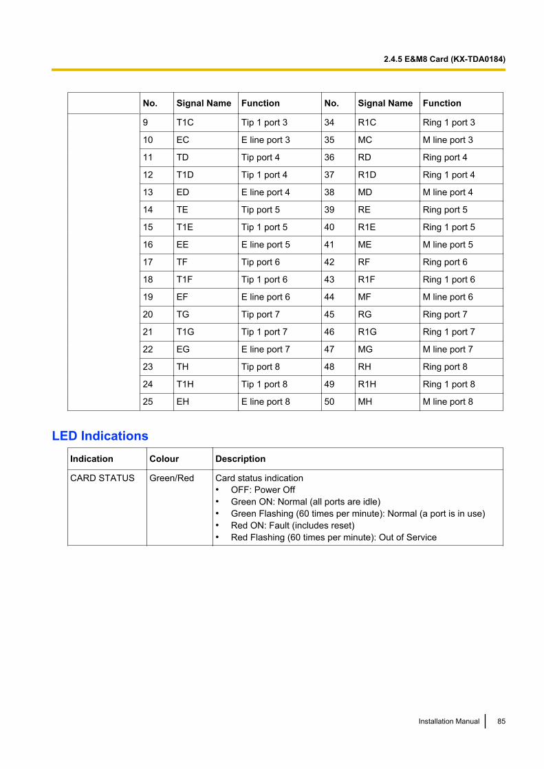
No. Signal Name Function No. Signal Name Function
9 T1C Tip 1 port 3 34 R1C Ring 1 port 3
10 EC E line port 3 35 MC M line port 3
11 TD Tip port 4 36 RD Ring port 4
12 T1D Tip 1 port 4 37 R1D Ring 1 port 4
13 ED E line port 4 38 MD M line port 4
14 TE Tip port 5 39 RE Ring port 5
15 T1E Tip 1 port 5 40 R1E Ring 1 port 5
16 EE E line port 5 41 ME M line port 5
17 TF Tip port 6 42 RF Ring port 6
18 T1F Tip 1 port 6 43 R1F Ring 1 port 6
19 EF E line port 6 44 MF M line port 6
20 TG Tip port 7 45 RG Ring port 7
21 T1G Tip 1 port 7 46 R1G Ring 1 port 7
22 EG E line port 7 47 MG M line port 7
23 TH Tip port 8 48 RH Ring port 8
24 T1H Tip 1 port 8 49 R1H Ring 1 port 8
25 EH E line port 8 50 MH M line port 8
LED IndicationsIndication Colour Description
CARD STATUS Green/Red Card status indication• OFF: Power Off• Green ON: Normal (all ports are idle)• Green Flashing (60 times per minute): Normal (a port is in use)• Red ON: Fault (includes reset)• Red Flashing (60 times per minute): Out of Service
Installation Manual 85
2.4.5 E&M8 Card (KX-TDA0184)
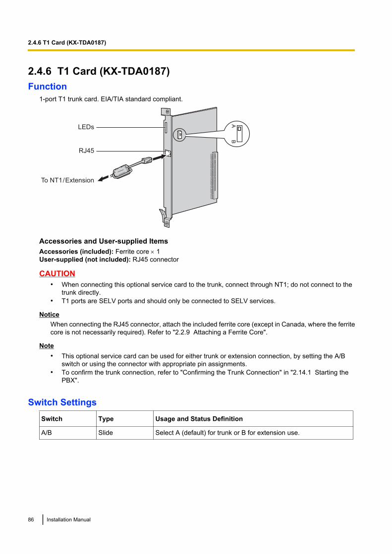
2.4.6 T1 Card (KX-TDA0187)Function
1-port T1 trunk card. EIA/TIA standard compliant.
LEDs
RJ45
To NT1 / Extension
AB
Accessories and User-supplied ItemsAccessories (included): Ferrite core ´ 1User-supplied (not included): RJ45 connector
CAUTION• When connecting this optional service card to the trunk, connect through NT1; do not connect to the
trunk directly.• T1 ports are SELV ports and should only be connected to SELV services.
NoticeWhen connecting the RJ45 connector, attach the included ferrite core (except in Canada, where the ferritecore is not necessarily required). Refer to "2.2.9 Attaching a Ferrite Core".
Note• This optional service card can be used for either trunk or extension connection, by setting the A/B
switch or using the connector with appropriate pin assignments.• To confirm the trunk connection, refer to "Confirming the Trunk Connection" in "2.14.1 Starting the
PBX".
Switch SettingsSwitch Type Usage and Status Definition
A/B Slide Select A (default) for trunk or B for extension use.
86 Installation Manual
2.4.6 T1 Card (KX-TDA0187)
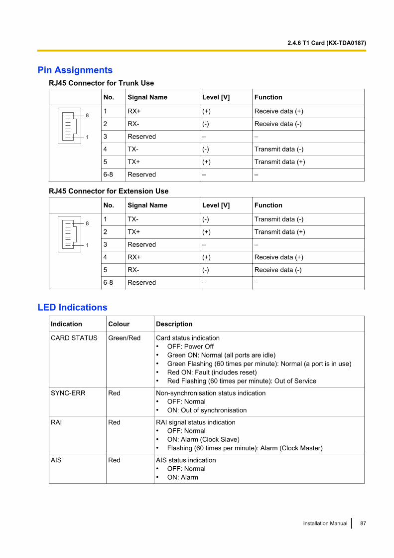
Pin AssignmentsRJ45 Connector for Trunk Use
No. Signal Name Level [V] Function
8
1
1 RX+ (+) Receive data (+)
2 RX- (-) Receive data (-)
3 Reserved – –
4 TX- (-) Transmit data (-)
5 TX+ (+) Transmit data (+)
6-8 Reserved – –
RJ45 Connector for Extension Use
No. Signal Name Level [V] Function
8
1
1 TX- (-) Transmit data (-)
2 TX+ (+) Transmit data (+)
3 Reserved – –
4 RX+ (+) Receive data (+)
5 RX- (-) Receive data (-)
6-8 Reserved – –
LED IndicationsIndication Colour Description
CARD STATUS Green/Red Card status indication• OFF: Power Off• Green ON: Normal (all ports are idle)• Green Flashing (60 times per minute): Normal (a port is in use)• Red ON: Fault (includes reset)• Red Flashing (60 times per minute): Out of Service
SYNC-ERR Red Non-synchronisation status indication• OFF: Normal• ON: Out of synchronisation
RAI Red RAI signal status indication• OFF: Normal• ON: Alarm (Clock Slave)• Flashing (60 times per minute): Alarm (Clock Master)
AIS Red AIS status indication• OFF: Normal• ON: Alarm
Installation Manual 87
2.4.6 T1 Card (KX-TDA0187)
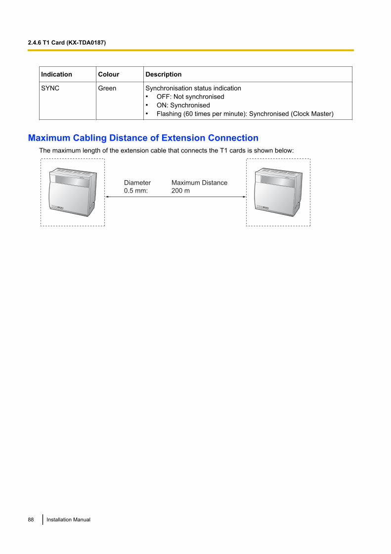
Indication Colour Description
SYNC Green Synchronisation status indication• OFF: Not synchronised• ON: Synchronised• Flashing (60 times per minute): Synchronised (Clock Master)
Maximum Cabling Distance of Extension ConnectionThe maximum length of the extension cable that connects the T1 cards is shown below:
Diameter Maximum Distance
0.5 mm: 200 m
88 Installation Manual
2.4.6 T1 Card (KX-TDA0187)
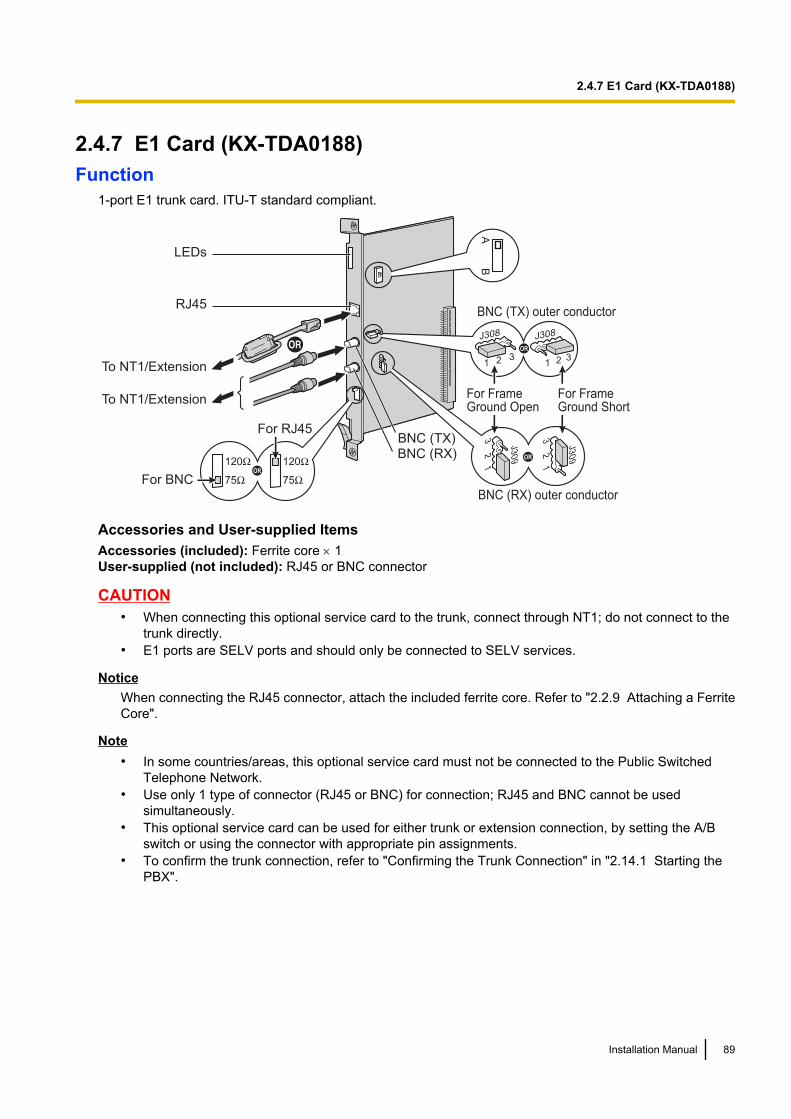
2.4.7 E1 Card (KX-TDA0188)Function
1-port E1 trunk card. ITU-T standard compliant.
LEDs
To NT1/Extension
To NT1/Extension
BNC (TX)BNC (RX)
BNC (TX) outer conductor
For Frame Ground Open
For Frame Ground Short
J308
1 2 31 2 3
J308
J30
9
12
3
J30
9
12
3
BNC (RX) outer conductor
RJ45
OR
OR
AB
For RJ45
For BNC
120Ω
75Ω
120Ω
75ΩOR
Accessories and User-supplied ItemsAccessories (included): Ferrite core ´ 1User-supplied (not included): RJ45 or BNC connector
CAUTION• When connecting this optional service card to the trunk, connect through NT1; do not connect to the
trunk directly.• E1 ports are SELV ports and should only be connected to SELV services.
NoticeWhen connecting the RJ45 connector, attach the included ferrite core. Refer to "2.2.9 Attaching a FerriteCore".
Note• In some countries/areas, this optional service card must not be connected to the Public Switched
Telephone Network.• Use only 1 type of connector (RJ45 or BNC) for connection; RJ45 and BNC cannot be used
simultaneously.• This optional service card can be used for either trunk or extension connection, by setting the A/B
switch or using the connector with appropriate pin assignments.• To confirm the trunk connection, refer to "Confirming the Trunk Connection" in "2.14.1 Starting the
PBX".
Installation Manual 89
2.4.7 E1 Card (KX-TDA0188)

Switch SettingsSwitch Type Usage and Status Definition
Termination Slide Select 120 W (default) or 75 W to match the connector type to beused.
A/B Slide When using an RJ45 connector, select A (default) for trunk or B forextension use.When using BNC connectors, make sure that A is selected.
Frame GroundShort
Short pin J308 is for BNC (TX) outer conductor, and J309 is for BNC (RX) outerconductor.
Connection of 1 and 2: Open (default)Connection of 2 and 3: Short
Pin AssignmentsRJ45 Connector for Trunk Use
No. Signal Name Level [V] Function
8
1
1 RX+ (+) Receive data (+)
2 RX- (-) Receive data (-)
3 Reserved – –
4 TX- (-) Transmit data (-)
5 TX+ (+) Transmit data (+)
6-8 Reserved – –
RJ45 Connector for Extension use
No. Signal Name Level [V] Function
8
1
1 TX- (-) Transmit data (-)
2 TX+ (+) Transmit data (+)
3 Reserved – –
4 RX+ (+) Receive data (+)
5 RX- (-) Receive data (-)
6-8 Reserved – –
BNC (coaxial) Connector (TX)
No. Signal Name Level [V] Function
1
2
1 TX+ (+) Transmit data (+)
2 TX- (-) Transmit data (-)
90 Installation Manual
2.4.7 E1 Card (KX-TDA0188)
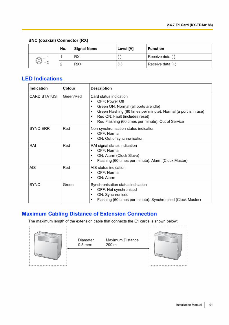
BNC (coaxial) Connector (RX)
No. Signal Name Level [V] Function
1
2
1 RX- (-) Receive data (-)
2 RX+ (+) Receive data (+)
LED IndicationsIndication Colour Description
CARD STATUS Green/Red Card status indication• OFF: Power Off• Green ON: Normal (all ports are idle)• Green Flashing (60 times per minute): Normal (a port is in use)• Red ON: Fault (includes reset)• Red Flashing (60 times per minute): Out of Service
SYNC-ERR Red Non-synchronisation status indication• OFF: Normal• ON: Out of synchronisation
RAI Red RAI signal status indication• OFF: Normal• ON: Alarm (Clock Slave)• Flashing (60 times per minute): Alarm (Clock Master)
AIS Red AIS status indication• OFF: Normal• ON: Alarm
SYNC Green Synchronisation status indication• OFF: Not synchronised• ON: Synchronised• Flashing (60 times per minute): Synchronised (Clock Master)
Maximum Cabling Distance of Extension ConnectionThe maximum length of the extension cable that connects the E1 cards is shown below:
Diameter Maximum Distance
0.5 mm: 200 m
Installation Manual 91
2.4.7 E1 Card (KX-TDA0188)
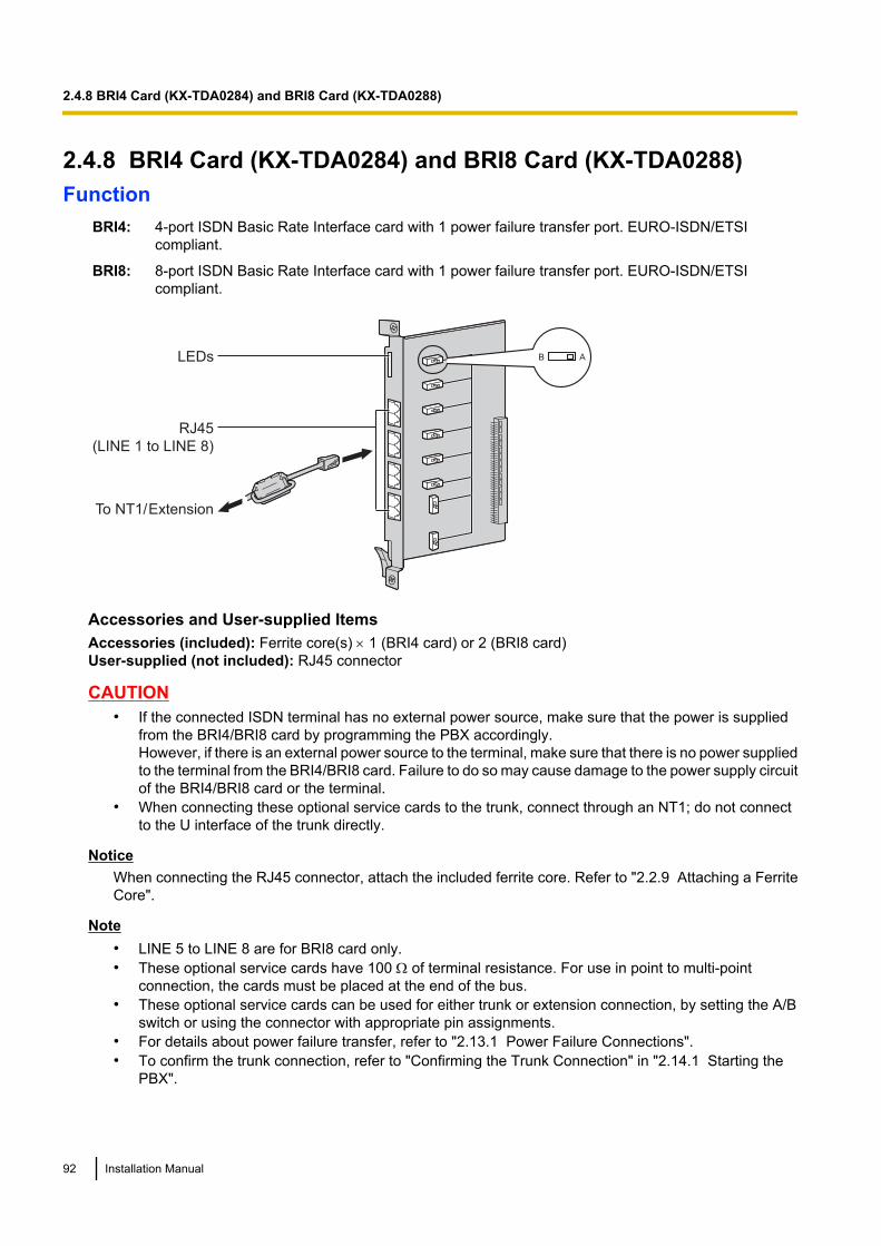
2.4.8 BRI4 Card (KX-TDA0284) and BRI8 Card (KX-TDA0288)Function
BRI4: 4-port ISDN Basic Rate Interface card with 1 power failure transfer port. EURO-ISDN/ETSIcompliant.
BRI8: 8-port ISDN Basic Rate Interface card with 1 power failure transfer port. EURO-ISDN/ETSIcompliant.
LEDs
RJ45
(LINE 1 to LINE 8)
AB
To NT1/ Extension
Accessories and User-supplied ItemsAccessories (included): Ferrite core(s) ´ 1 (BRI4 card) or 2 (BRI8 card)User-supplied (not included): RJ45 connector
CAUTION• If the connected ISDN terminal has no external power source, make sure that the power is supplied
from the BRI4/BRI8 card by programming the PBX accordingly.However, if there is an external power source to the terminal, make sure that there is no power suppliedto the terminal from the BRI4/BRI8 card. Failure to do so may cause damage to the power supply circuitof the BRI4/BRI8 card or the terminal.
• When connecting these optional service cards to the trunk, connect through an NT1; do not connectto the U interface of the trunk directly.
NoticeWhen connecting the RJ45 connector, attach the included ferrite core. Refer to "2.2.9 Attaching a FerriteCore".
Note• LINE 5 to LINE 8 are for BRI8 card only.• These optional service cards have 100 W of terminal resistance. For use in point to multi-point
connection, the cards must be placed at the end of the bus.• These optional service cards can be used for either trunk or extension connection, by setting the A/B
switch or using the connector with appropriate pin assignments.• For details about power failure transfer, refer to "2.13.1 Power Failure Connections".• To confirm the trunk connection, refer to "Confirming the Trunk Connection" in "2.14.1 Starting the
PBX".
92 Installation Manual
2.4.8 BRI4 Card (KX-TDA0284) and BRI8 Card (KX-TDA0288)
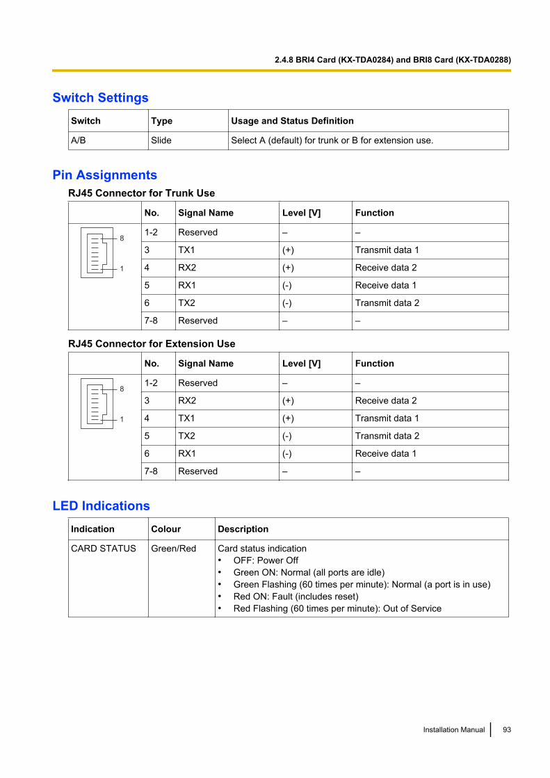
Switch SettingsSwitch Type Usage and Status Definition
A/B Slide Select A (default) for trunk or B for extension use.
Pin AssignmentsRJ45 Connector for Trunk Use
No. Signal Name Level [V] Function
8
1
1-2 Reserved – –
3 TX1 (+) Transmit data 1
4 RX2 (+) Receive data 2
5 RX1 (-) Receive data 1
6 TX2 (-) Transmit data 2
7-8 Reserved – –
RJ45 Connector for Extension Use
No. Signal Name Level [V] Function
8
1
1-2 Reserved – –
3 RX2 (+) Receive data 2
4 TX1 (+) Transmit data 1
5 TX2 (-) Transmit data 2
6 RX1 (-) Receive data 1
7-8 Reserved – –
LED IndicationsIndication Colour Description
CARD STATUS Green/Red Card status indication• OFF: Power Off• Green ON: Normal (all ports are idle)• Green Flashing (60 times per minute): Normal (a port is in use)• Red ON: Fault (includes reset)• Red Flashing (60 times per minute): Out of Service
Installation Manual 93
2.4.8 BRI4 Card (KX-TDA0284) and BRI8 Card (KX-TDA0288)
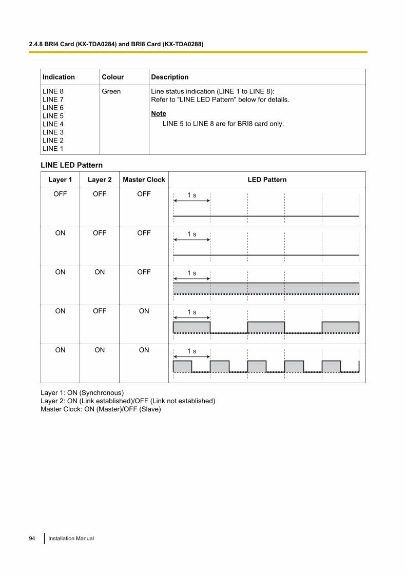
Indication Colour Description
LINE 8LINE 7LINE 6LINE 5LINE 4LINE 3LINE 2LINE 1
Green Line status indication (LINE 1 to LINE 8):Refer to "LINE LED Pattern" below for details.
NoteLINE 5 to LINE 8 are for BRI8 card only.
LINE LED Pattern
Layer 1 Layer 2 Master Clock LED Pattern
OFF OFF OFF 1 s
ON OFF OFF 1 s
ON ON OFF 1 s
ON OFF ON 1 s
ON ON ON 1 s
Layer 1: ON (Synchronous)Layer 2: ON (Link established)/OFF (Link not established)Master Clock: ON (Master)/OFF (Slave)
94 Installation Manual
2.4.8 BRI4 Card (KX-TDA0284) and BRI8 Card (KX-TDA0288)
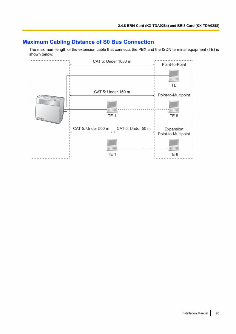
Maximum Cabling Distance of S0 Bus ConnectionThe maximum length of the extension cable that connects the PBX and the ISDN terminal equipment (TE) isshown below:
CAT 5: Under 1000 m
TE
Point-to-Point
Expansion
Point-to-Multipoint
Point-to-Multipoint
TE 1 TE 8
TE 8TE 1
CAT 5: Under 150 m
CAT 5: Under 500 m CAT 5: Under 50 m
Installation Manual 95
2.4.8 BRI4 Card (KX-TDA0284) and BRI8 Card (KX-TDA0288)
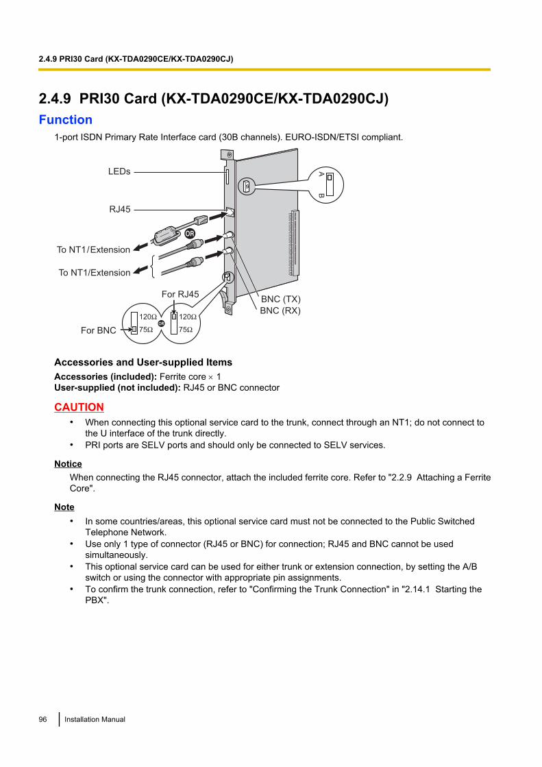
2.4.9 PRI30 Card (KX-TDA0290CE/KX-TDA0290CJ)Function
1-port ISDN Primary Rate Interface card (30B channels). EURO-ISDN/ETSI compliant.
LEDs
RJ45
To NT1/Extension
To NT1 / Extension
BNC (TX)
BNC (RX)
AB
For RJ45
For BNC
120Ω
75Ω
120Ω
75ΩOR
Accessories and User-supplied ItemsAccessories (included): Ferrite core ´ 1User-supplied (not included): RJ45 or BNC connector
CAUTION• When connecting this optional service card to the trunk, connect through an NT1; do not connect to
the U interface of the trunk directly.• PRI ports are SELV ports and should only be connected to SELV services.
NoticeWhen connecting the RJ45 connector, attach the included ferrite core. Refer to "2.2.9 Attaching a FerriteCore".
Note• In some countries/areas, this optional service card must not be connected to the Public Switched
Telephone Network.• Use only 1 type of connector (RJ45 or BNC) for connection; RJ45 and BNC cannot be used
simultaneously.• This optional service card can be used for either trunk or extension connection, by setting the A/B
switch or using the connector with appropriate pin assignments.• To confirm the trunk connection, refer to "Confirming the Trunk Connection" in "2.14.1 Starting the
PBX".
96 Installation Manual
2.4.9 PRI30 Card (KX-TDA0290CE/KX-TDA0290CJ)
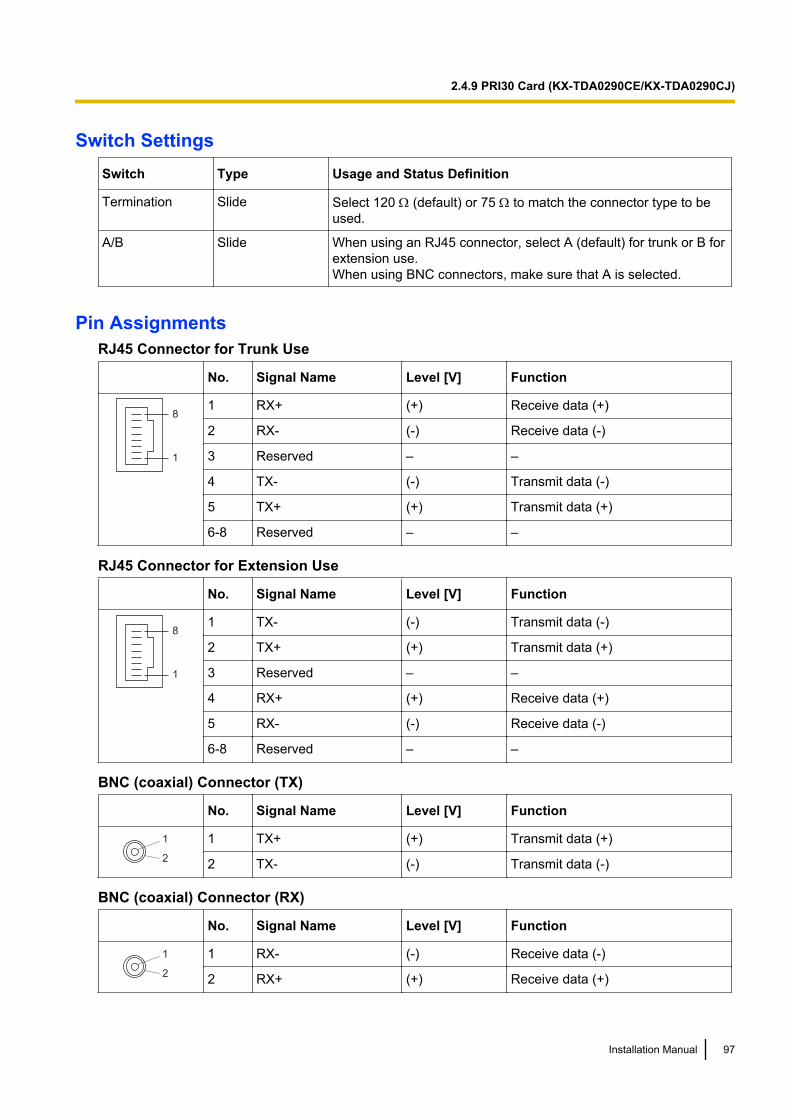
Switch SettingsSwitch Type Usage and Status Definition
Termination Slide Select 120 W (default) or 75 W to match the connector type to beused.
A/B Slide When using an RJ45 connector, select A (default) for trunk or B forextension use.When using BNC connectors, make sure that A is selected.
Pin AssignmentsRJ45 Connector for Trunk Use
No. Signal Name Level [V] Function
8
1
1 RX+ (+) Receive data (+)
2 RX- (-) Receive data (-)
3 Reserved – –
4 TX- (-) Transmit data (-)
5 TX+ (+) Transmit data (+)
6-8 Reserved – –
RJ45 Connector for Extension Use
No. Signal Name Level [V] Function
8
1
1 TX- (-) Transmit data (-)
2 TX+ (+) Transmit data (+)
3 Reserved – –
4 RX+ (+) Receive data (+)
5 RX- (-) Receive data (-)
6-8 Reserved – –
BNC (coaxial) Connector (TX)
No. Signal Name Level [V] Function
1
2
1 TX+ (+) Transmit data (+)
2 TX- (-) Transmit data (-)
BNC (coaxial) Connector (RX)
No. Signal Name Level [V] Function
1
2
1 RX- (-) Receive data (-)
2 RX+ (+) Receive data (+)
Installation Manual 97
2.4.9 PRI30 Card (KX-TDA0290CE/KX-TDA0290CJ)
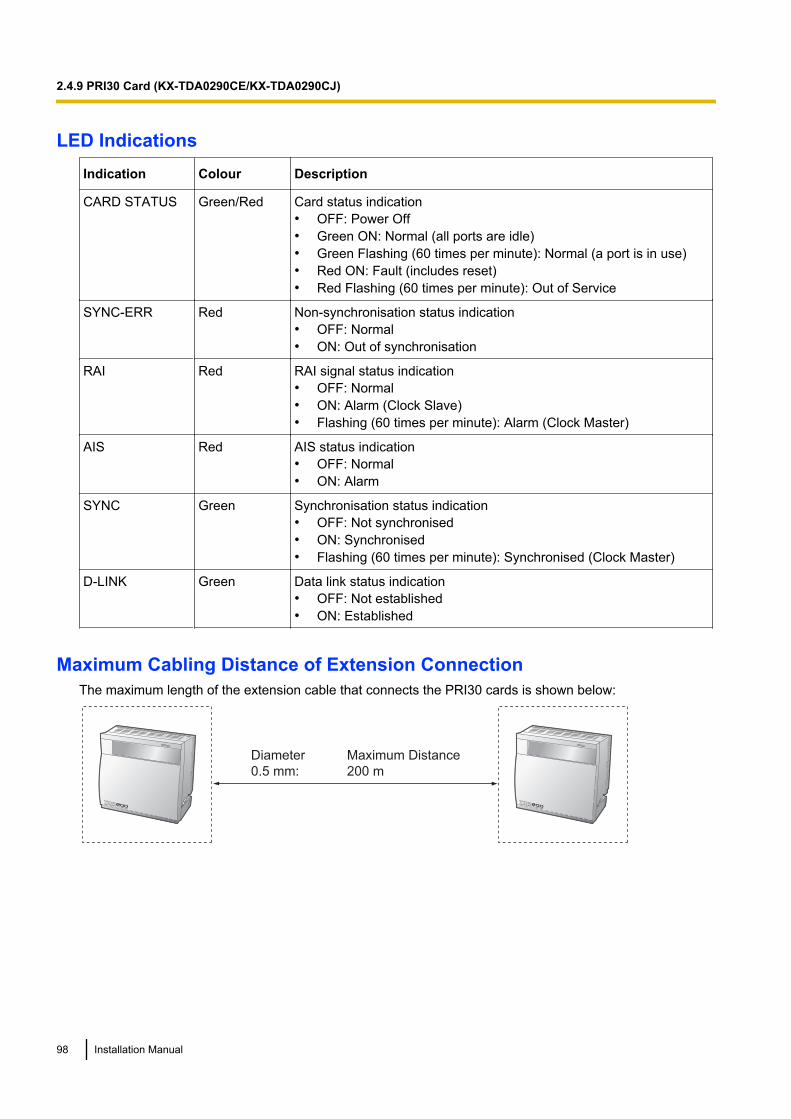
LED IndicationsIndication Colour Description
CARD STATUS Green/Red Card status indication• OFF: Power Off• Green ON: Normal (all ports are idle)• Green Flashing (60 times per minute): Normal (a port is in use)• Red ON: Fault (includes reset)• Red Flashing (60 times per minute): Out of Service
SYNC-ERR Red Non-synchronisation status indication• OFF: Normal• ON: Out of synchronisation
RAI Red RAI signal status indication• OFF: Normal• ON: Alarm (Clock Slave)• Flashing (60 times per minute): Alarm (Clock Master)
AIS Red AIS status indication• OFF: Normal• ON: Alarm
SYNC Green Synchronisation status indication• OFF: Not synchronised• ON: Synchronised• Flashing (60 times per minute): Synchronised (Clock Master)
D-LINK Green Data link status indication• OFF: Not established• ON: Established
Maximum Cabling Distance of Extension ConnectionThe maximum length of the extension cable that connects the PRI30 cards is shown below:
Diameter Maximum Distance
0.5 mm: 200 m
98 Installation Manual
2.4.9 PRI30 Card (KX-TDA0290CE/KX-TDA0290CJ)
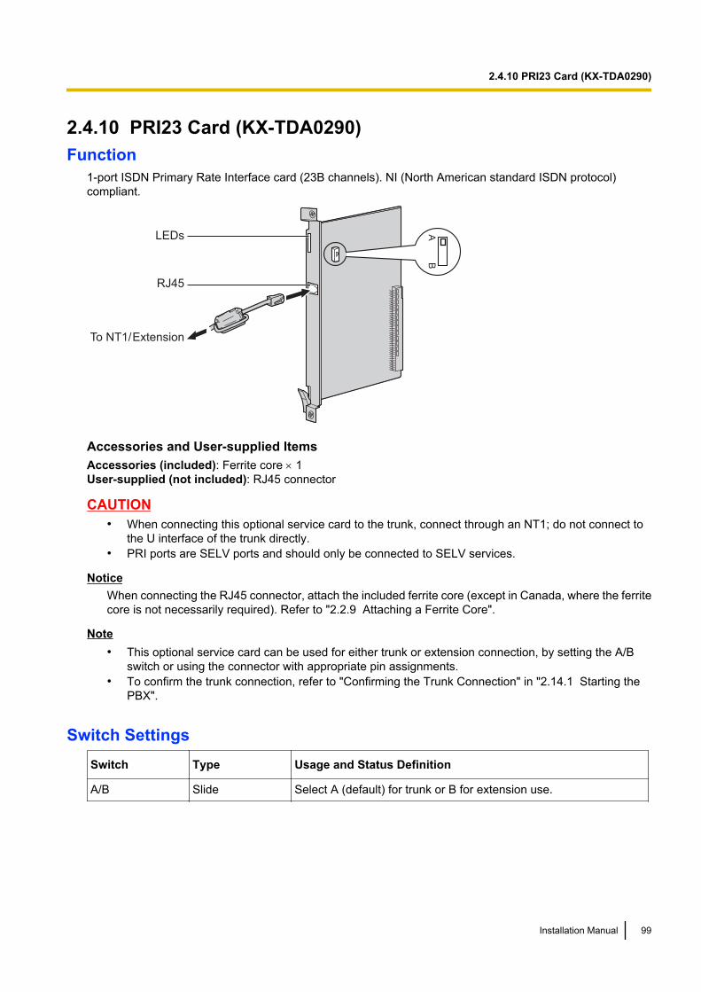
2.4.10 PRI23 Card (KX-TDA0290)Function
1-port ISDN Primary Rate Interface card (23B channels). NI (North American standard ISDN protocol)compliant.
LEDs
RJ45
To NT1/ Extension
AB
Accessories and User-supplied ItemsAccessories (included): Ferrite core ´ 1User-supplied (not included): RJ45 connector
CAUTION• When connecting this optional service card to the trunk, connect through an NT1; do not connect to
the U interface of the trunk directly.• PRI ports are SELV ports and should only be connected to SELV services.
NoticeWhen connecting the RJ45 connector, attach the included ferrite core (except in Canada, where the ferritecore is not necessarily required). Refer to "2.2.9 Attaching a Ferrite Core".
Note• This optional service card can be used for either trunk or extension connection, by setting the A/B
switch or using the connector with appropriate pin assignments.• To confirm the trunk connection, refer to "Confirming the Trunk Connection" in "2.14.1 Starting the
PBX".
Switch SettingsSwitch Type Usage and Status Definition
A/B Slide Select A (default) for trunk or B for extension use.
Installation Manual 99
2.4.10 PRI23 Card (KX-TDA0290)

Pin AssignmentsRJ45 Connector for Trunk Use
No. Signal Name Level [V] Function
8
1
1 RX+ (+) Receive data (+)
2 RX- (-) Receive data (-)
3 Reserved – –
4 TX- (-) Transmit data (-)
5 TX+ (+) Transmit data (+)
6-8 Reserved – –
RJ45 Connector for Extension Use
No. Signal Name Level [V] Function
8
1
1 TX- (-) Transmit data (-)
2 TX+ (+) Transmit data (+)
3 Reserved – –
4 RX+ (+) Receive data (+)
5 RX- (-) Receive data (-)
6-8 Reserved – –
LED IndicationsIndication Colour Description
CARD STATUS Green/Red Card status indication• OFF: Power Off• Green ON: Normal (all ports are idle)• Green Flashing (60 times per minute): Normal (a port is in use)• Red ON: Fault (includes reset)• Red Flashing (60 times per minute): Out of Service
SYNC-ERR Red Non-synchronisation status indication• OFF: Normal• ON: Out of synchronisation
RAI Red RAI signal status indication• OFF: Normal• ON: Alarm (Clock Slave)• Flashing (60 times per minute): Alarm (Clock Master)
AIS Red AIS status indication• OFF: Normal• ON: Alarm
100 Installation Manual
2.4.10 PRI23 Card (KX-TDA0290)
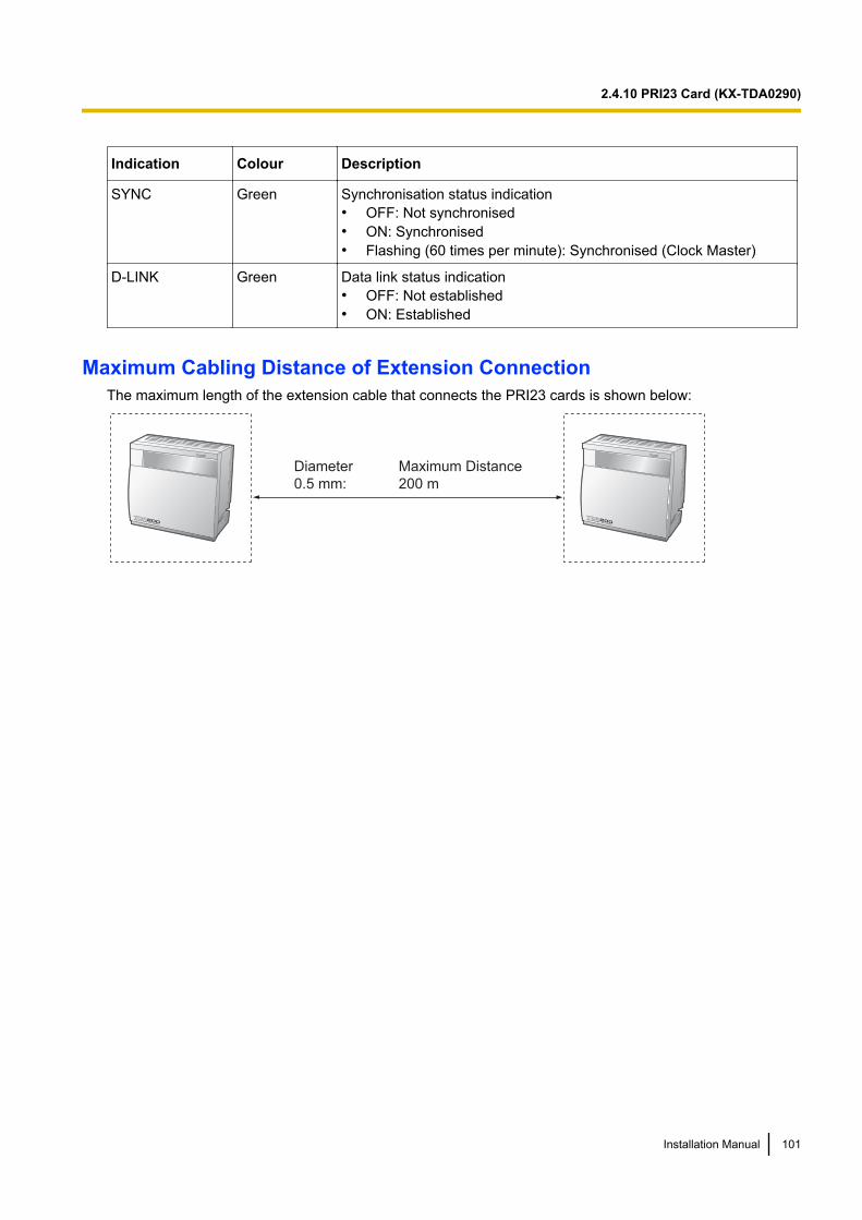
Indication Colour Description
SYNC Green Synchronisation status indication• OFF: Not synchronised• ON: Synchronised• Flashing (60 times per minute): Synchronised (Clock Master)
D-LINK Green Data link status indication• OFF: Not established• ON: Established
Maximum Cabling Distance of Extension ConnectionThe maximum length of the extension cable that connects the PRI23 cards is shown below:
Diameter Maximum Distance
0.5 mm: 200 m
Installation Manual 101
2.4.10 PRI23 Card (KX-TDA0290)
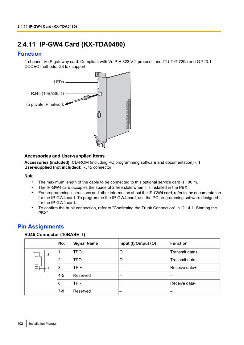
2.4.11 IP-GW4 Card (KX-TDA0480)Function
4-channel VoIP gateway card. Compliant with VoIP H.323 V.2 protocol, and ITU-T G.729a and G.723.1CODEC methods. G3 fax support.
RJ45 (10BASE-T)
LEDs
To private IP network
Accessories and User-supplied ItemsAccessories (included): CD-ROM (including PC programming software and documentation) ´ 1User-supplied (not included): RJ45 connector
Note• The maximum length of the cable to be connected to this optional service card is 100 m.• The IP-GW4 card occupies the space of 2 free slots when it is installed in the PBX.• For programming instructions and other information about the IP-GW4 card, refer to the documentation
for the IP-GW4 card. To programme the IP-GW4 card, use the PC programming software designedfor the IP-GW4 card.
• To confirm the trunk connection, refer to "Confirming the Trunk Connection" in "2.14.1 Starting thePBX".
Pin AssignmentsRJ45 Connector (10BASE-T)
No. Signal Name Input (I)/Output (O) Function
8
1
1 TPO+ O Transmit data+
2 TPO- O Transmit data-
3 TPI+ I Receive data+
4-5 Reserved – –
6 TPI- I Receive data-
7-8 Reserved – –
102 Installation Manual
2.4.11 IP-GW4 Card (KX-TDA0480)
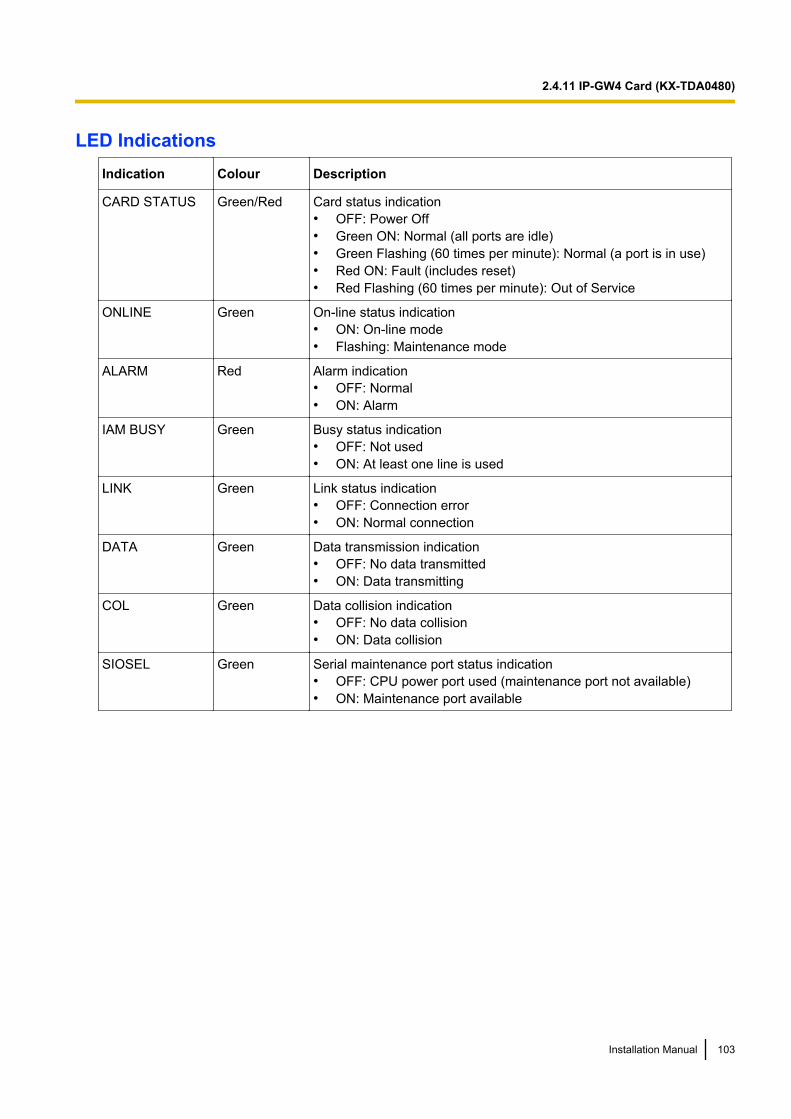
LED IndicationsIndication Colour Description
CARD STATUS Green/Red Card status indication• OFF: Power Off• Green ON: Normal (all ports are idle)• Green Flashing (60 times per minute): Normal (a port is in use)• Red ON: Fault (includes reset)• Red Flashing (60 times per minute): Out of Service
ONLINE Green On-line status indication• ON: On-line mode• Flashing: Maintenance mode
ALARM Red Alarm indication• OFF: Normal• ON: Alarm
IAM BUSY Green Busy status indication• OFF: Not used• ON: At least one line is used
LINK Green Link status indication• OFF: Connection error• ON: Normal connection
DATA Green Data transmission indication• OFF: No data transmitted• ON: Data transmitting
COL Green Data collision indication• OFF: No data collision• ON: Data collision
SIOSEL Green Serial maintenance port status indication• OFF: CPU power port used (maintenance port not available)• ON: Maintenance port available
Installation Manual 103
2.4.11 IP-GW4 Card (KX-TDA0480)
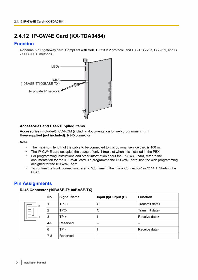
2.4.12 IP-GW4E Card (KX-TDA0484)Function
4-channel VoIP gateway card. Compliant with VoIP H.323 V.2 protocol, and ITU-T G.729a, G.723.1, and G.711 CODEC methods.
LEDs
RJ45(10BASE-T/100BASE-TX)
To private IP network
Accessories and User-supplied ItemsAccessories (included): CD-ROM (including documentation for web programming) ´ 1User-supplied (not included): RJ45 connector
Note• The maximum length of the cable to be connected to this optional service card is 100 m.• The IP-GW4E card occupies the space of only 1 free slot when it is installed in the PBX.• For programming instructions and other information about the IP-GW4E card, refer to the
documentation for the IP-GW4E card. To programme the IP-GW4E card, use the web programmingdesigned for the IP-GW4E card.
• To confirm the trunk connection, refer to "Confirming the Trunk Connection" in "2.14.1 Starting thePBX".
Pin AssignmentsRJ45 Connector (10BASE-T/100BASE-TX)
No. Signal Name Input (I)/Output (O) Function
8
1
1 TPO+ O Transmit data+
2 TPO- O Transmit data-
3 TPI+ I Receive data+
4-5 Reserved – –
6 TPI- I Receive data-
7-8 Reserved – –
104 Installation Manual
2.4.12 IP-GW4E Card (KX-TDA0484)

LED IndicationsIndication Colour Description
CARD STATUS Green/Red Card status indication• OFF: Power Off• Green ON: Normal (all ports are idle)• Green Flashing (60 times per minute): Normal (a port is in use)• Red ON: Fault (includes reset)• Red Flashing (60 times per minute): Out of Service
ONLINE Green On-line status indication• ON: On-line mode• OFF: Off-line mode• Flashing: Maintenance mode
NoteIf the LINK indicator is OFF, the ONLINE indicator will also be OFF.
ALARM Red Alarm indication• OFF: Normal• ON: Alarm
VoIP BUSY Green VoIP (H.323) process indication• OFF: VoIP process inactive• ON: VoIP process active
LINK Green Link status indication• OFF: Connection error• ON: Normal connection
DATA Green Data transmission indication• OFF: No data transmitted• ON: Data transmitting
Installation Manual 105
2.4.12 IP-GW4E Card (KX-TDA0484)
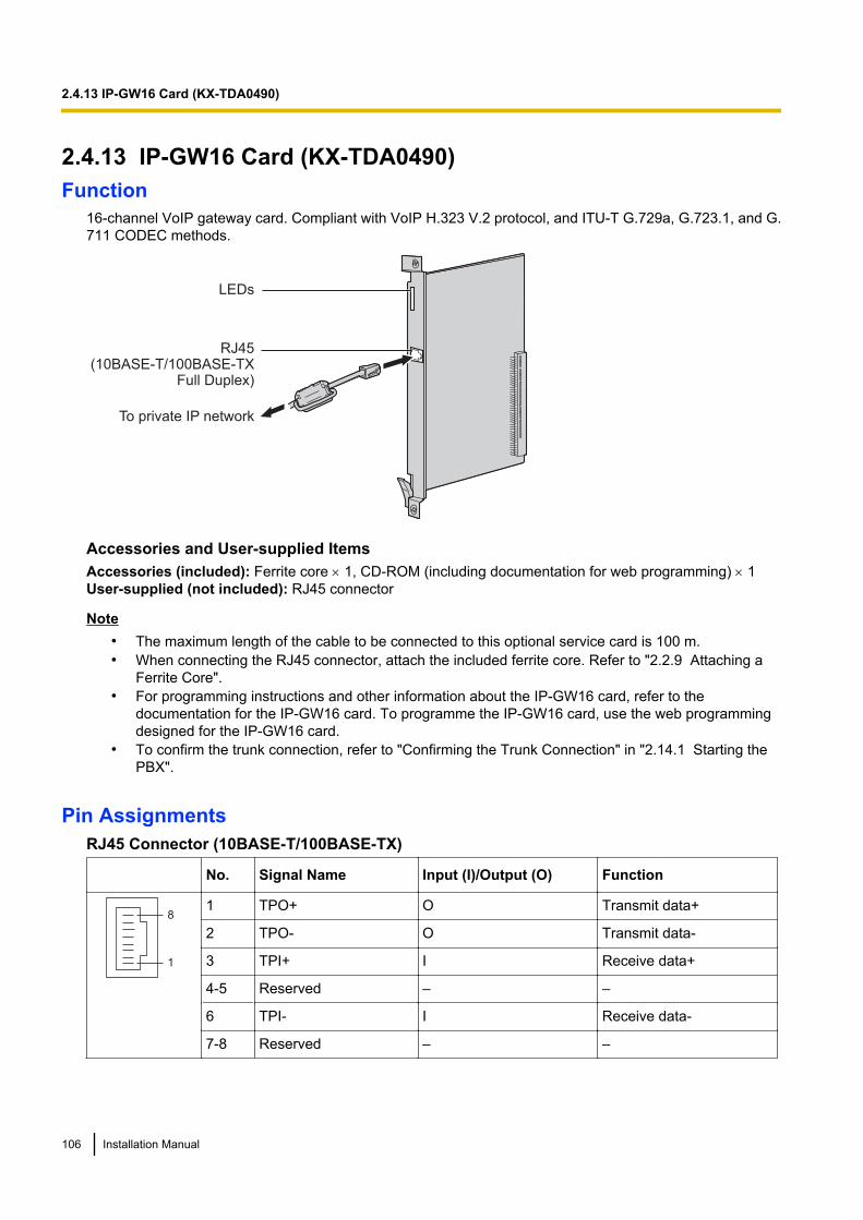
2.4.13 IP-GW16 Card (KX-TDA0490)Function
16-channel VoIP gateway card. Compliant with VoIP H.323 V.2 protocol, and ITU-T G.729a, G.723.1, and G.711 CODEC methods.
LEDs
RJ45(10BASE-T/100BASE-TX
Full Duplex)
To private IP network
Accessories and User-supplied ItemsAccessories (included): Ferrite core ´ 1, CD-ROM (including documentation for web programming) ´ 1User-supplied (not included): RJ45 connector
Note• The maximum length of the cable to be connected to this optional service card is 100 m.• When connecting the RJ45 connector, attach the included ferrite core. Refer to "2.2.9 Attaching a
Ferrite Core".• For programming instructions and other information about the IP-GW16 card, refer to the
documentation for the IP-GW16 card. To programme the IP-GW16 card, use the web programmingdesigned for the IP-GW16 card.
• To confirm the trunk connection, refer to "Confirming the Trunk Connection" in "2.14.1 Starting thePBX".
Pin AssignmentsRJ45 Connector (10BASE-T/100BASE-TX)
No. Signal Name Input (I)/Output (O) Function
8
1
1 TPO+ O Transmit data+
2 TPO- O Transmit data-
3 TPI+ I Receive data+
4-5 Reserved – –
6 TPI- I Receive data-
7-8 Reserved – –
106 Installation Manual
2.4.13 IP-GW16 Card (KX-TDA0490)
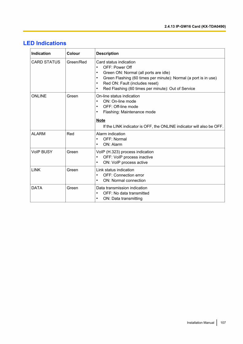
LED IndicationsIndication Colour Description
CARD STATUS Green/Red Card status indication• OFF: Power Off• Green ON: Normal (all ports are idle)• Green Flashing (60 times per minute): Normal (a port is in use)• Red ON: Fault (includes reset)• Red Flashing (60 times per minute): Out of Service
ONLINE Green On-line status indication• ON: On-line mode• OFF: Off-line mode• Flashing: Maintenance mode
NoteIf the LINK indicator is OFF, the ONLINE indicator will also be OFF.
ALARM Red Alarm indication• OFF: Normal• ON: Alarm
VoIP BUSY Green VoIP (H.323) process indication• OFF: VoIP process inactive• ON: VoIP process active
LINK Green Link status indication• OFF: Connection error• ON: Normal connection
DATA Green Data transmission indication• OFF: No data transmitted• ON: Data transmitting
Installation Manual 107
2.4.13 IP-GW16 Card (KX-TDA0490)
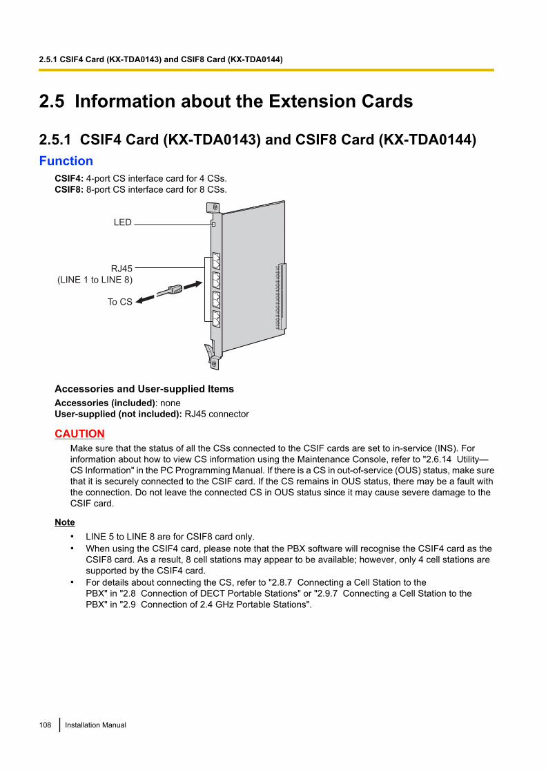
2.5 Information about the Extension Cards
2.5.1 CSIF4 Card (KX-TDA0143) and CSIF8 Card (KX-TDA0144)Function
CSIF4: 4-port CS interface card for 4 CSs.CSIF8: 8-port CS interface card for 8 CSs.
RJ45
(LINE 1 to LINE 8)
LED
To CS
Accessories and User-supplied ItemsAccessories (included): noneUser-supplied (not included): RJ45 connector
CAUTIONMake sure that the status of all the CSs connected to the CSIF cards are set to in-service (INS). Forinformation about how to view CS information using the Maintenance Console, refer to "2.6.14 Utility—CS Information" in the PC Programming Manual. If there is a CS in out-of-service (OUS) status, make surethat it is securely connected to the CSIF card. If the CS remains in OUS status, there may be a fault withthe connection. Do not leave the connected CS in OUS status since it may cause severe damage to theCSIF card.
Note• LINE 5 to LINE 8 are for CSIF8 card only.• When using the CSIF4 card, please note that the PBX software will recognise the CSIF4 card as the
CSIF8 card. As a result, 8 cell stations may appear to be available; however, only 4 cell stations aresupported by the CSIF4 card.
• For details about connecting the CS, refer to "2.8.7 Connecting a Cell Station to thePBX" in "2.8 Connection of DECT Portable Stations" or "2.9.7 Connecting a Cell Station to thePBX" in "2.9 Connection of 2.4 GHz Portable Stations".
108 Installation Manual
2.5.1 CSIF4 Card (KX-TDA0143) and CSIF8 Card (KX-TDA0144)
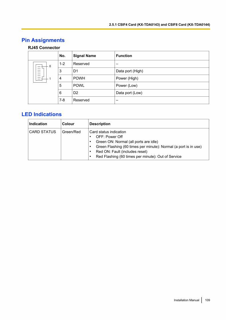
Pin AssignmentsRJ45 Connector
No. Signal Name Function
8
1
1-2 Reserved –
3 D1 Data port (High)
4 POWH Power (High)
5 POWL Power (Low)
6 D2 Data port (Low)
7-8 Reserved –
LED IndicationsIndication Colour Description
CARD STATUS Green/Red Card status indication• OFF: Power Off• Green ON: Normal (all ports are idle)• Green Flashing (60 times per minute): Normal (a port is in use)• Red ON: Fault (includes reset)• Red Flashing (60 times per minute): Out of Service
Installation Manual 109
2.5.1 CSIF4 Card (KX-TDA0143) and CSIF8 Card (KX-TDA0144)
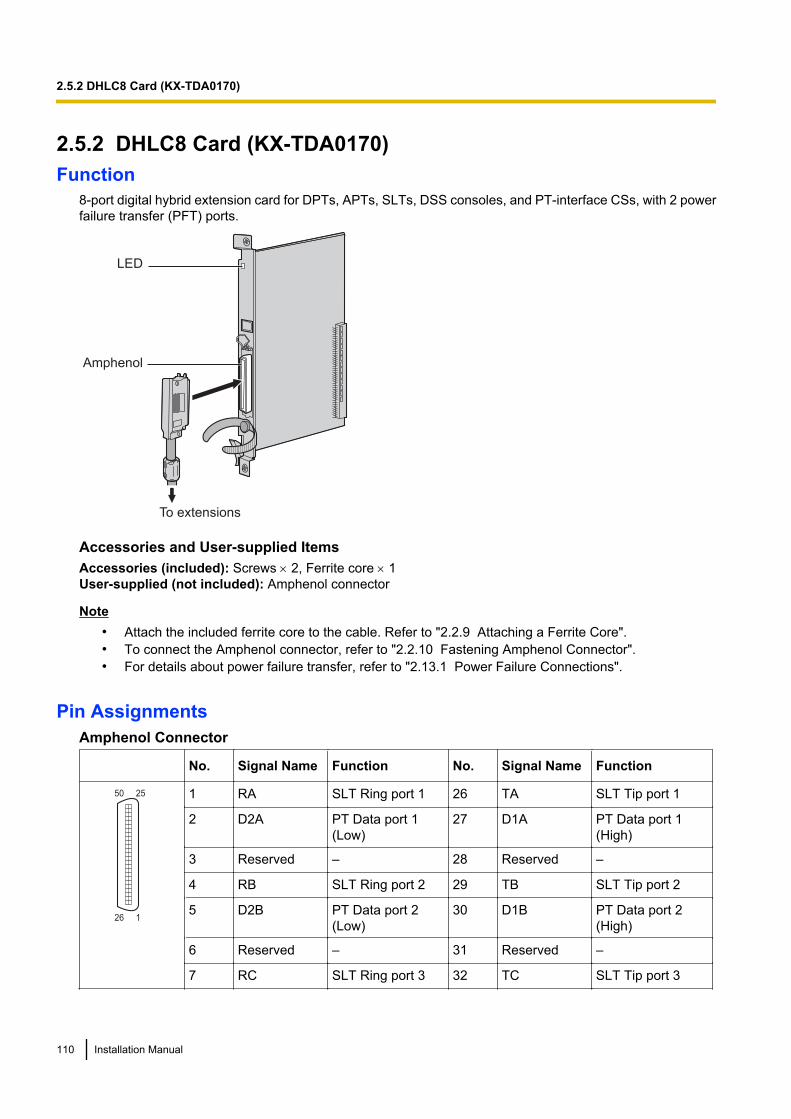
2.5.2 DHLC8 Card (KX-TDA0170)Function
8-port digital hybrid extension card for DPTs, APTs, SLTs, DSS consoles, and PT-interface CSs, with 2 powerfailure transfer (PFT) ports.
LED
Amphenol
To extensions
Accessories and User-supplied ItemsAccessories (included): Screws ´ 2, Ferrite core ´ 1User-supplied (not included): Amphenol connector
Note• Attach the included ferrite core to the cable. Refer to "2.2.9 Attaching a Ferrite Core".• To connect the Amphenol connector, refer to "2.2.10 Fastening Amphenol Connector".• For details about power failure transfer, refer to "2.13.1 Power Failure Connections".
Pin AssignmentsAmphenol Connector
No. Signal Name Function No. Signal Name Function
50 25
26 1
1 RA SLT Ring port 1 26 TA SLT Tip port 1
2 D2A PT Data port 1(Low)
27 D1A PT Data port 1(High)
3 Reserved – 28 Reserved –
4 RB SLT Ring port 2 29 TB SLT Tip port 2
5 D2B PT Data port 2(Low)
30 D1B PT Data port 2(High)
6 Reserved – 31 Reserved –
7 RC SLT Ring port 3 32 TC SLT Tip port 3
110 Installation Manual
2.5.2 DHLC8 Card (KX-TDA0170)
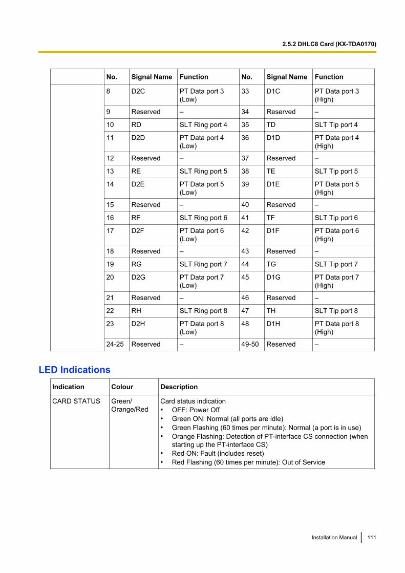
No. Signal Name Function No. Signal Name Function
8 D2C PT Data port 3(Low)
33 D1C PT Data port 3(High)
9 Reserved – 34 Reserved –
10 RD SLT Ring port 4 35 TD SLT Tip port 4
11 D2D PT Data port 4(Low)
36 D1D PT Data port 4(High)
12 Reserved – 37 Reserved –
13 RE SLT Ring port 5 38 TE SLT Tip port 5
14 D2E PT Data port 5(Low)
39 D1E PT Data port 5(High)
15 Reserved – 40 Reserved –
16 RF SLT Ring port 6 41 TF SLT Tip port 6
17 D2F PT Data port 6(Low)
42 D1F PT Data port 6(High)
18 Reserved – 43 Reserved –
19 RG SLT Ring port 7 44 TG SLT Tip port 7
20 D2G PT Data port 7(Low)
45 D1G PT Data port 7(High)
21 Reserved – 46 Reserved –
22 RH SLT Ring port 8 47 TH SLT Tip port 8
23 D2H PT Data port 8(Low)
48 D1H PT Data port 8(High)
24-25 Reserved – 49-50 Reserved –
LED IndicationsIndication Colour Description
CARD STATUS Green/Orange/Red
Card status indication• OFF: Power Off• Green ON: Normal (all ports are idle)• Green Flashing (60 times per minute): Normal (a port is in use)• Orange Flashing: Detection of PT-interface CS connection (when
starting up the PT-interface CS)• Red ON: Fault (includes reset)• Red Flashing (60 times per minute): Out of Service
Installation Manual 111
2.5.2 DHLC8 Card (KX-TDA0170)
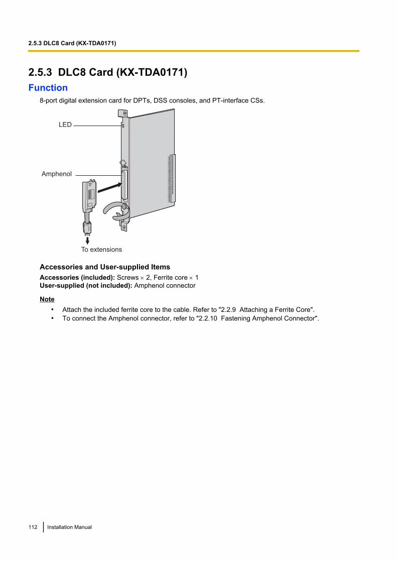
2.5.3 DLC8 Card (KX-TDA0171)Function
8-port digital extension card for DPTs, DSS consoles, and PT-interface CSs.
LED
Amphenol
To extensions
Accessories and User-supplied ItemsAccessories (included): Screws ´ 2, Ferrite core ´ 1User-supplied (not included): Amphenol connector
Note• Attach the included ferrite core to the cable. Refer to "2.2.9 Attaching a Ferrite Core".• To connect the Amphenol connector, refer to "2.2.10 Fastening Amphenol Connector".
112 Installation Manual
2.5.3 DLC8 Card (KX-TDA0171)
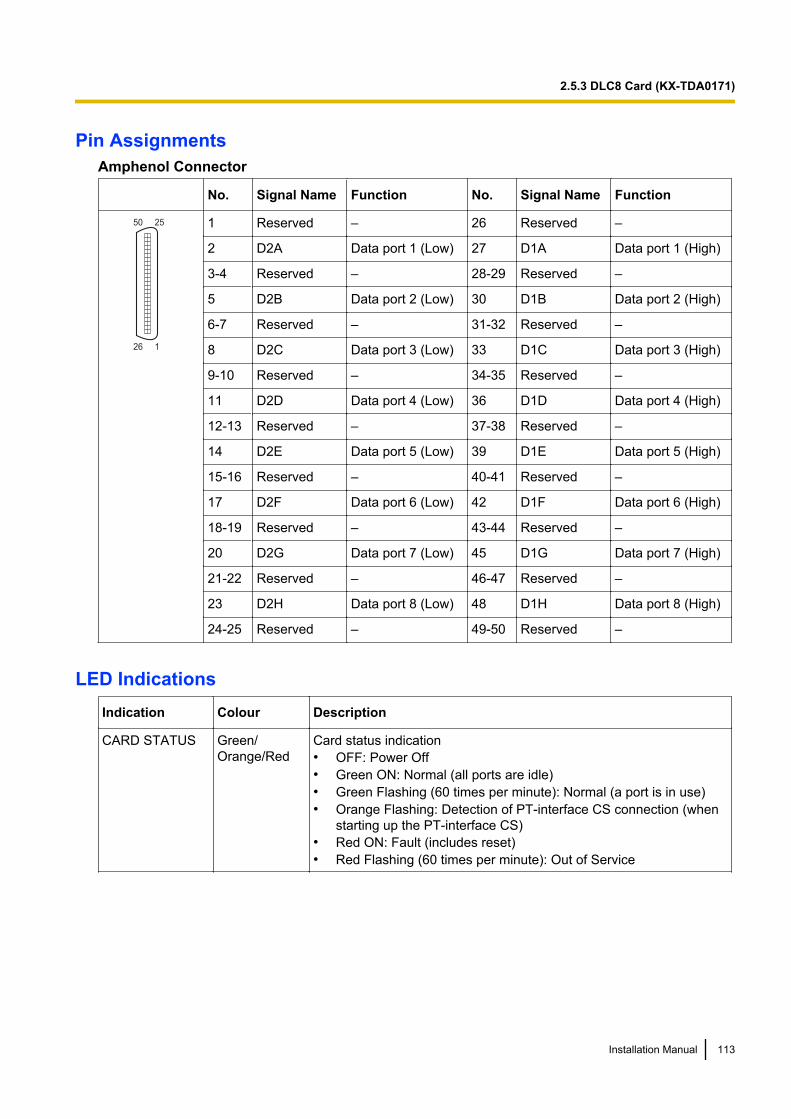
Pin AssignmentsAmphenol Connector
No. Signal Name Function No. Signal Name Function
50 25
26 1
1 Reserved – 26 Reserved –
2 D2A Data port 1 (Low) 27 D1A Data port 1 (High)
3-4 Reserved – 28-29 Reserved –
5 D2B Data port 2 (Low) 30 D1B Data port 2 (High)
6-7 Reserved – 31-32 Reserved –
8 D2C Data port 3 (Low) 33 D1C Data port 3 (High)
9-10 Reserved – 34-35 Reserved –
11 D2D Data port 4 (Low) 36 D1D Data port 4 (High)
12-13 Reserved – 37-38 Reserved –
14 D2E Data port 5 (Low) 39 D1E Data port 5 (High)
15-16 Reserved – 40-41 Reserved –
17 D2F Data port 6 (Low) 42 D1F Data port 6 (High)
18-19 Reserved – 43-44 Reserved –
20 D2G Data port 7 (Low) 45 D1G Data port 7 (High)
21-22 Reserved – 46-47 Reserved –
23 D2H Data port 8 (Low) 48 D1H Data port 8 (High)
24-25 Reserved – 49-50 Reserved –
LED IndicationsIndication Colour Description
CARD STATUS Green/Orange/Red
Card status indication• OFF: Power Off• Green ON: Normal (all ports are idle)• Green Flashing (60 times per minute): Normal (a port is in use)• Orange Flashing: Detection of PT-interface CS connection (when
starting up the PT-interface CS)• Red ON: Fault (includes reset)• Red Flashing (60 times per minute): Out of Service
Installation Manual 113
2.5.3 DLC8 Card (KX-TDA0171)
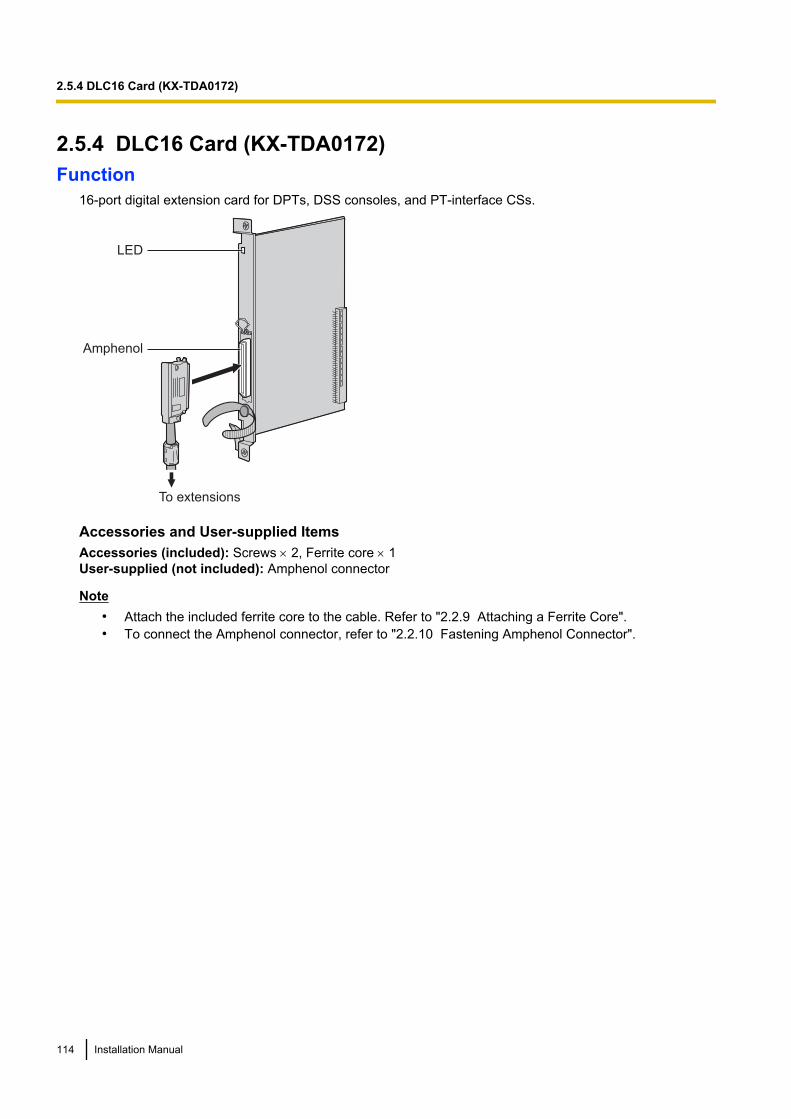
2.5.4 DLC16 Card (KX-TDA0172)Function
16-port digital extension card for DPTs, DSS consoles, and PT-interface CSs.
LED
Amphenol
To extensions
Accessories and User-supplied ItemsAccessories (included): Screws ´ 2, Ferrite core ´ 1User-supplied (not included): Amphenol connector
Note• Attach the included ferrite core to the cable. Refer to "2.2.9 Attaching a Ferrite Core".• To connect the Amphenol connector, refer to "2.2.10 Fastening Amphenol Connector".
114 Installation Manual
2.5.4 DLC16 Card (KX-TDA0172)
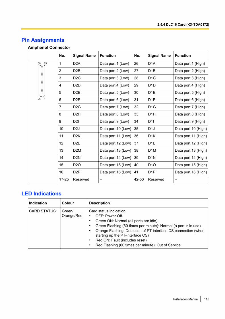
Pin AssignmentsAmphenol Connector
No. Signal Name Function No. Signal Name Function
50 25
26 1
1 D2A Data port 1 (Low) 26 D1A Data port 1 (High)
2 D2B Data port 2 (Low) 27 D1B Data port 2 (High)
3 D2C Data port 3 (Low) 28 D1C Data port 3 (High)
4 D2D Data port 4 (Low) 29 D1D Data port 4 (High)
5 D2E Data port 5 (Low) 30 D1E Data port 5 (High)
6 D2F Data port 6 (Low) 31 D1F Data port 6 (High)
7 D2G Data port 7 (Low) 32 D1G Data port 7 (High)
8 D2H Data port 8 (Low) 33 D1H Data port 8 (High)
9 D2I Data port 9 (Low) 34 D1I Data port 9 (High)
10 D2J Data port 10 (Low) 35 D1J Data port 10 (High)
11 D2K Data port 11 (Low) 36 D1K Data port 11 (High)
12 D2L Data port 12 (Low) 37 D1L Data port 12 (High)
13 D2M Data port 13 (Low) 38 D1M Data port 13 (High)
14 D2N Data port 14 (Low) 39 D1N Data port 14 (High)
15 D2O Data port 15 (Low) 40 D1O Data port 15 (High)
16 D2P Data port 16 (Low) 41 D1P Data port 16 (High)
17-25 Reserved – 42-50 Reserved –
LED IndicationsIndication Colour Description
CARD STATUS Green/Orange/Red
Card status indication• OFF: Power Off• Green ON: Normal (all ports are idle)• Green Flashing (60 times per minute): Normal (a port is in use)• Orange Flashing: Detection of PT-interface CS connection (when
starting up the PT-interface CS)• Red ON: Fault (includes reset)• Red Flashing (60 times per minute): Out of Service
Installation Manual 115
2.5.4 DLC16 Card (KX-TDA0172)
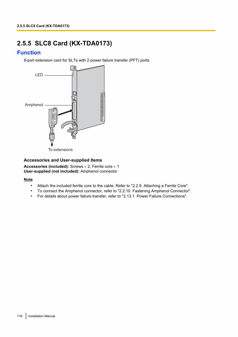
2.5.5 SLC8 Card (KX-TDA0173)Function
8-port extension card for SLTs with 2 power failure transfer (PFT) ports.
LED
Amphenol
To extensions
Accessories and User-supplied ItemsAccessories (included): Screws ´ 2, Ferrite core ´ 1User-supplied (not included): Amphenol connector
Note• Attach the included ferrite core to the cable. Refer to "2.2.9 Attaching a Ferrite Core".• To connect the Amphenol connector, refer to "2.2.10 Fastening Amphenol Connector".• For details about power failure transfer, refer to "2.13.1 Power Failure Connections".
116 Installation Manual
2.5.5 SLC8 Card (KX-TDA0173)
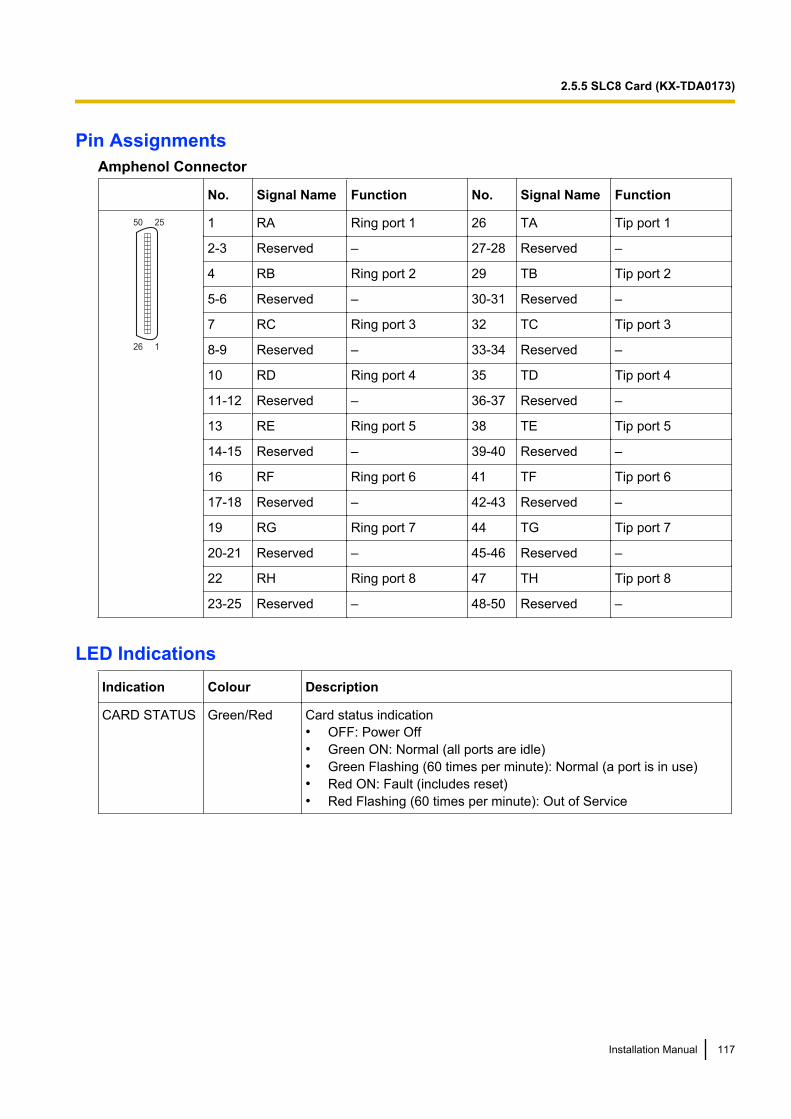
Pin AssignmentsAmphenol Connector
No. Signal Name Function No. Signal Name Function
50 25
26 1
1 RA Ring port 1 26 TA Tip port 1
2-3 Reserved – 27-28 Reserved –
4 RB Ring port 2 29 TB Tip port 2
5-6 Reserved – 30-31 Reserved –
7 RC Ring port 3 32 TC Tip port 3
8-9 Reserved – 33-34 Reserved –
10 RD Ring port 4 35 TD Tip port 4
11-12 Reserved – 36-37 Reserved –
13 RE Ring port 5 38 TE Tip port 5
14-15 Reserved – 39-40 Reserved –
16 RF Ring port 6 41 TF Tip port 6
17-18 Reserved – 42-43 Reserved –
19 RG Ring port 7 44 TG Tip port 7
20-21 Reserved – 45-46 Reserved –
22 RH Ring port 8 47 TH Tip port 8
23-25 Reserved – 48-50 Reserved –
LED IndicationsIndication Colour Description
CARD STATUS Green/Red Card status indication• OFF: Power Off• Green ON: Normal (all ports are idle)• Green Flashing (60 times per minute): Normal (a port is in use)• Red ON: Fault (includes reset)• Red Flashing (60 times per minute): Out of Service
Installation Manual 117
2.5.5 SLC8 Card (KX-TDA0173)
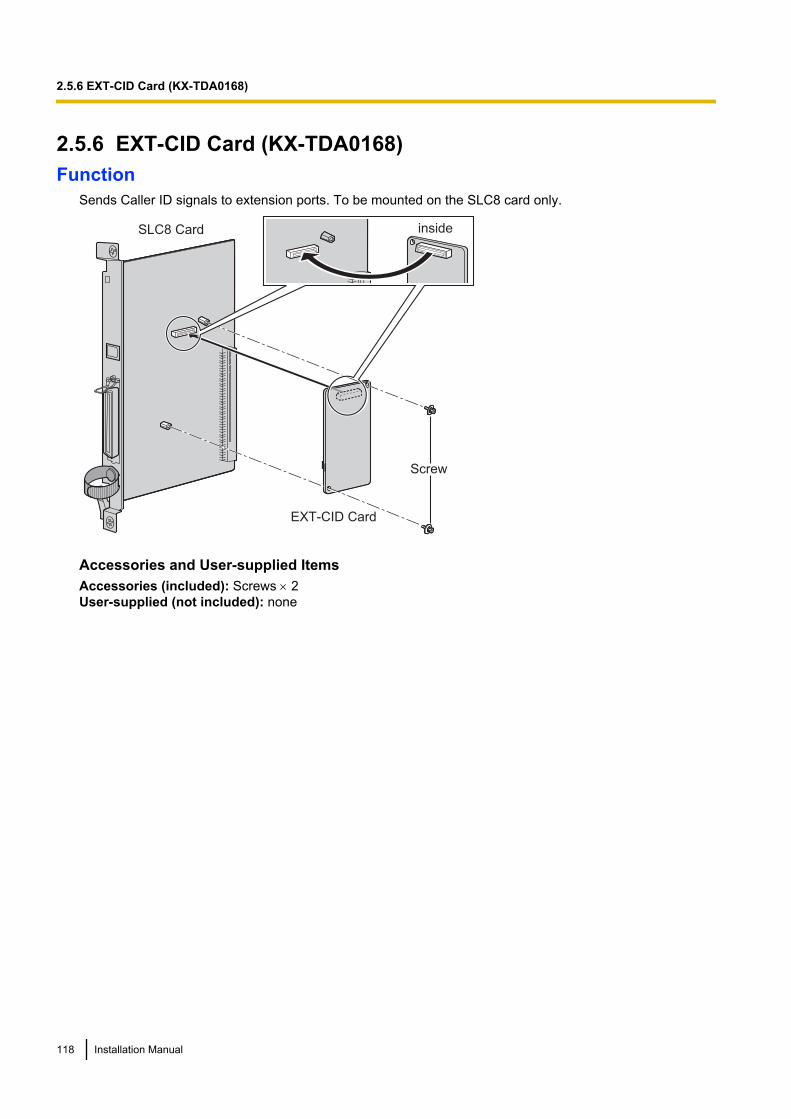
2.5.6 EXT-CID Card (KX-TDA0168)Function
Sends Caller ID signals to extension ports. To be mounted on the SLC8 card only.
EXT-CID Card
Screw
SLC8 Card inside
Accessories and User-supplied ItemsAccessories (included): Screws ´ 2User-supplied (not included): none
118 Installation Manual
2.5.6 EXT-CID Card (KX-TDA0168)
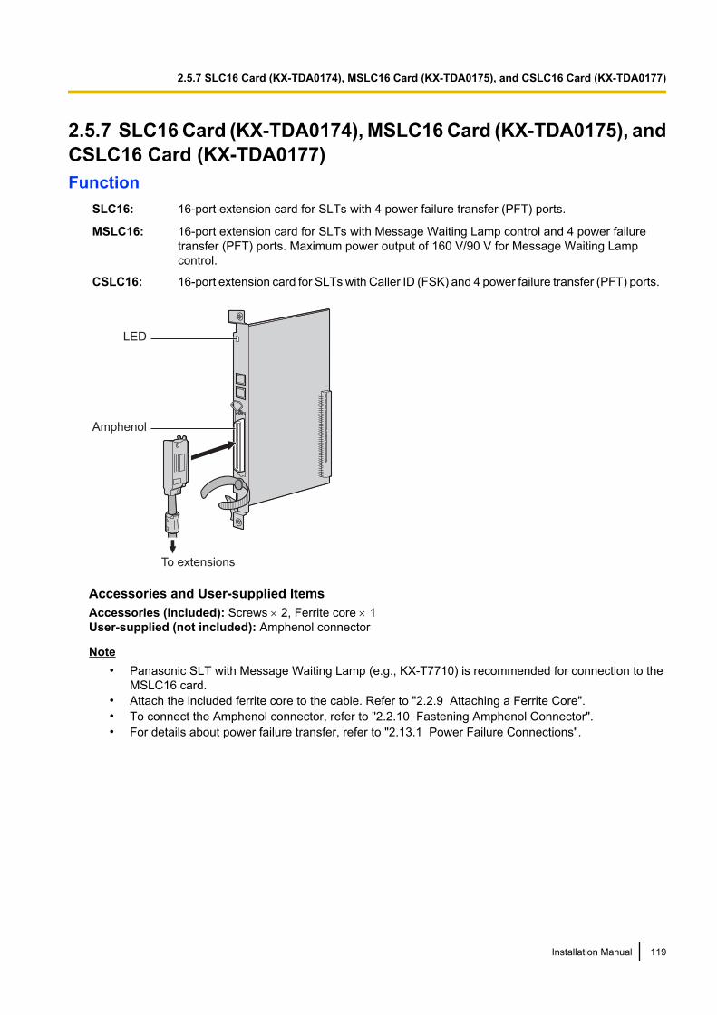
2.5.7 SLC16 Card (KX-TDA0174), MSLC16 Card (KX-TDA0175), andCSLC16 Card (KX-TDA0177)Function
SLC16: 16-port extension card for SLTs with 4 power failure transfer (PFT) ports.
MSLC16: 16-port extension card for SLTs with Message Waiting Lamp control and 4 power failuretransfer (PFT) ports. Maximum power output of 160 V/90 V for Message Waiting Lampcontrol.
CSLC16: 16-port extension card for SLTs with Caller ID (FSK) and 4 power failure transfer (PFT) ports.
LED
Amphenol
To extensions
Accessories and User-supplied ItemsAccessories (included): Screws ´ 2, Ferrite core ´ 1User-supplied (not included): Amphenol connector
Note• Panasonic SLT with Message Waiting Lamp (e.g., KX-T7710) is recommended for connection to the
MSLC16 card.• Attach the included ferrite core to the cable. Refer to "2.2.9 Attaching a Ferrite Core".• To connect the Amphenol connector, refer to "2.2.10 Fastening Amphenol Connector".• For details about power failure transfer, refer to "2.13.1 Power Failure Connections".
Installation Manual 119
2.5.7 SLC16 Card (KX-TDA0174), MSLC16 Card (KX-TDA0175), and CSLC16 Card (KX-TDA0177)
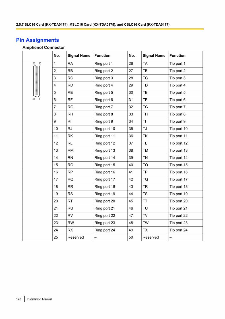
Pin AssignmentsAmphenol Connector
No. Signal Name Function No. Signal Name Function
50 25
26 1
1 RA Ring port 1 26 TA Tip port 1
2 RB Ring port 2 27 TB Tip port 2
3 RC Ring port 3 28 TC Tip port 3
4 RD Ring port 4 29 TD Tip port 4
5 RE Ring port 5 30 TE Tip port 5
6 RF Ring port 6 31 TF Tip port 6
7 RG Ring port 7 32 TG Tip port 7
8 RH Ring port 8 33 TH Tip port 8
9 RI Ring port 9 34 TI Tip port 9
10 RJ Ring port 10 35 TJ Tip port 10
11 RK Ring port 11 36 TK Tip port 11
12 RL Ring port 12 37 TL Tip port 12
13 RM Ring port 13 38 TM Tip port 13
14 RN Ring port 14 39 TN Tip port 14
15 RO Ring port 15 40 TO Tip port 15
16 RP Ring port 16 41 TP Tip port 16
17 RQ Ring port 17 42 TQ Tip port 17
18 RR Ring port 18 43 TR Tip port 18
19 RS Ring port 19 44 TS Tip port 19
20 RT Ring port 20 45 TT Tip port 20
21 RU Ring port 21 46 TU Tip port 21
22 RV Ring port 22 47 TV Tip port 22
23 RW Ring port 23 48 TW Tip port 23
24 RX Ring port 24 49 TX Tip port 24
25 Reserved – 50 Reserved –
120 Installation Manual
2.5.7 SLC16 Card (KX-TDA0174), MSLC16 Card (KX-TDA0175), and CSLC16 Card (KX-TDA0177)

LED IndicationsIndication Colour Description
CARD STATUS Green/Red Card status indication• OFF: Power Off• Green ON: Normal (all ports are idle)• Green Flashing (60 times per minute): Normal (a port is in use)• Red ON: Fault (includes reset)• Red Flashing (60 times per minute): Out of Service
Installation Manual 121
2.5.7 SLC16 Card (KX-TDA0174), MSLC16 Card (KX-TDA0175), and CSLC16 Card (KX-TDA0177)
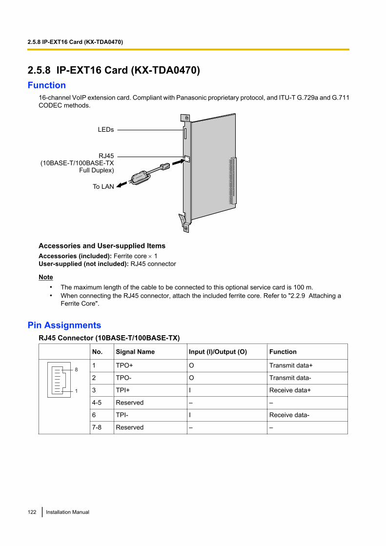
2.5.8 IP-EXT16 Card (KX-TDA0470)Function
16-channel VoIP extension card. Compliant with Panasonic proprietary protocol, and ITU-T G.729a and G.711CODEC methods.
LEDs
RJ45(10BASE-T/100BASE-TX
Full Duplex)
To LAN
Accessories and User-supplied ItemsAccessories (included): Ferrite core ´ 1User-supplied (not included): RJ45 connector
Note• The maximum length of the cable to be connected to this optional service card is 100 m.• When connecting the RJ45 connector, attach the included ferrite core. Refer to "2.2.9 Attaching a
Ferrite Core".
Pin AssignmentsRJ45 Connector (10BASE-T/100BASE-TX)
No. Signal Name Input (I)/Output (O) Function
8
1
1 TPO+ O Transmit data+
2 TPO- O Transmit data-
3 TPI+ I Receive data+
4-5 Reserved – –
6 TPI- I Receive data-
7-8 Reserved – –
122 Installation Manual
2.5.8 IP-EXT16 Card (KX-TDA0470)

LED IndicationsIndication Colour Description
CARD STATUS Green/Red Card status indication• OFF: Power Off• Green ON: Normal (all ports are idle)• Green Flashing (60 times per minute): Normal (a port is in use)• Red ON: Fault (includes reset)• Red Flashing (60 times per minute): Out of Service
ONLINE Green On-line status indication• ON: At least one port is in use (an IP-PT is connected)• OFF: No ports are in use (no IP-PTs are connected)
NoteIf the LINK indicator is OFF, the ONLINE indicator will also be OFF.
ALARM Red Alarm indication• OFF: Normal• ON: Alarm
VoIP BUSY Green Panasonic proprietary VoIP protocol process indication• OFF: VoIP process inactive• ON: VoIP process active
LINK Green Link status indication• OFF: Connection error• ON: Normal connection
DATA Green Data transmission indication• OFF: No data transmitted• ON: Data transmitting
Installation Manual 123
2.5.8 IP-EXT16 Card (KX-TDA0470)
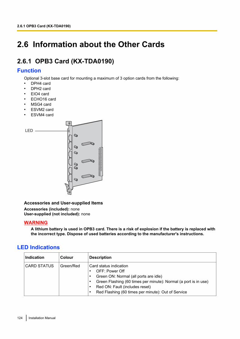
2.6 Information about the Other Cards
2.6.1 OPB3 Card (KX-TDA0190)Function
Optional 3-slot base card for mounting a maximum of 3 option cards from the following:• DPH4 card• DPH2 card• EIO4 card• ECHO16 card• MSG4 card• ESVM2 card• ESVM4 card
LED
Accessories and User-supplied ItemsAccessories (included): noneUser-supplied (not included): none
WARNINGA lithium battery is used in OPB3 card. There is a risk of explosion if the battery is replaced withthe incorrect type. Dispose of used batteries according to the manufacturer's instructions.
LED IndicationsIndication Colour Description
CARD STATUS Green/Red Card status indication• OFF: Power Off• Green ON: Normal (all ports are idle)• Green Flashing (60 times per minute): Normal (a port is in use)• Red ON: Fault (includes reset)• Red Flashing (60 times per minute): Out of Service
124 Installation Manual
2.6.1 OPB3 Card (KX-TDA0190)
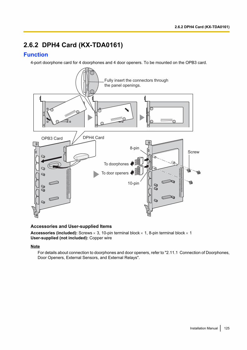
2.6.2 DPH4 Card (KX-TDA0161)Function
4-port doorphone card for 4 doorphones and 4 door openers. To be mounted on the OPB3 card.
Fully insert the connectors through
the panel openings.
OPB3 Card DPH4 Card
8-pin
10-pin
Screw
To doorphones
To door openers
Accessories and User-supplied ItemsAccessories (included): Screws ´ 3, 10-pin terminal block ´ 1, 8-pin terminal block ´ 1User-supplied (not included): Copper wire
NoteFor details about connection to doorphones and door openers, refer to "2.11.1 Connection of Doorphones,Door Openers, External Sensors, and External Relays".
Installation Manual 125
2.6.2 DPH4 Card (KX-TDA0161)
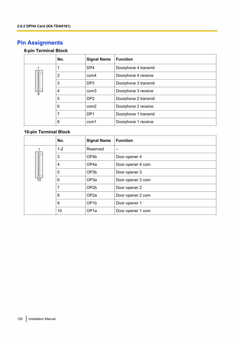
Pin Assignments8-pin Terminal Block
No. Signal Name Function
8
1 1 DP4 Doorphone 4 transmit
2 com4 Doorphone 4 receive
3 DP3 Doorphone 3 transmit
4 com3 Doorphone 3 receive
5 DP2 Doorphone 2 transmit
6 com2 Doorphone 2 receive
7 DP1 Doorphone 1 transmit
8 com1 Doorphone 1 receive
10-pin Terminal Block
No. Signal Name Function
10
1 1-2 Reserved –
3 OP4b Door opener 4
4 OP4a Door opener 4 com
5 OP3b Door opener 3
6 OP3a Door opener 3 com
7 OP2b Door opener 2
8 OP2a Door opener 2 com
9 OP1b Door opener 1
10 OP1a Door opener 1 com
126 Installation Manual
2.6.2 DPH4 Card (KX-TDA0161)

2.6.3 DPH2 Card (KX-TDA0162)Function
2-port doorphone card for 2 German-type doorphones and 2 door openers. To be mounted on the OPB3 card.
Fully insert the connectors through
the panel openings.
OPB3 Card DPH2 Card
8-pin
10-pin
Screw
To doorphones/door openers
Accessories and User-supplied ItemsAccessories (included): Screws ´ 3, 10-pin terminal block ´ 1, 8-pin terminal block ´ 1User-supplied (not included): Copper wire
NoteFor details about connection to doorphones and door openers, refer to "2.11.1 Connection of Doorphones,Door Openers, External Sensors, and External Relays".
Installation Manual 127
2.6.3 DPH2 Card (KX-TDA0162)
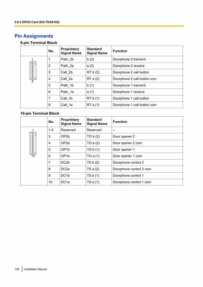
Pin Assignments8-pin Terminal Block
No. ProprietarySignal Name
StandardSignal Name Function
8
1 1 Path_2b b (2) Doorphone 2 transmit
2 Path_2a a (2) Doorphone 2 receive
3 Call_2b RT b (2) Doorphone 2 call button
4 Call_2a RT a (2) Doorphone 2 call button com
5 Path_1b b (1) Doorphone 1 transmit
6 Path_1a a (1) Doorphone 1 receive
7 Call_1b RT b (1) Doorphone 1 call button
8 Call_1a RT a (1) Doorphone 1 call button com
10-pin Terminal Block
No. ProprietarySignal Name
StandardSignal Name Function
10
1 1-2 Reserved Reserved –
3 OP2b TO b (2) Door opener 2
4 OP2a TO a (2) Door opener 2 com
5 OP1b TO b (1) Door opener 1
6 OP1a TO a (1) Door opener 1 com
7 DC2b TS b (2) Doorphone control 2
8 DC2a TS a (2) Doorphone control 2 com
9 DC1b TS b (1) Doorphone control 1
10 DC1a TS a (1) Doorphone control 1 com
128 Installation Manual
2.6.3 DPH2 Card (KX-TDA0162)
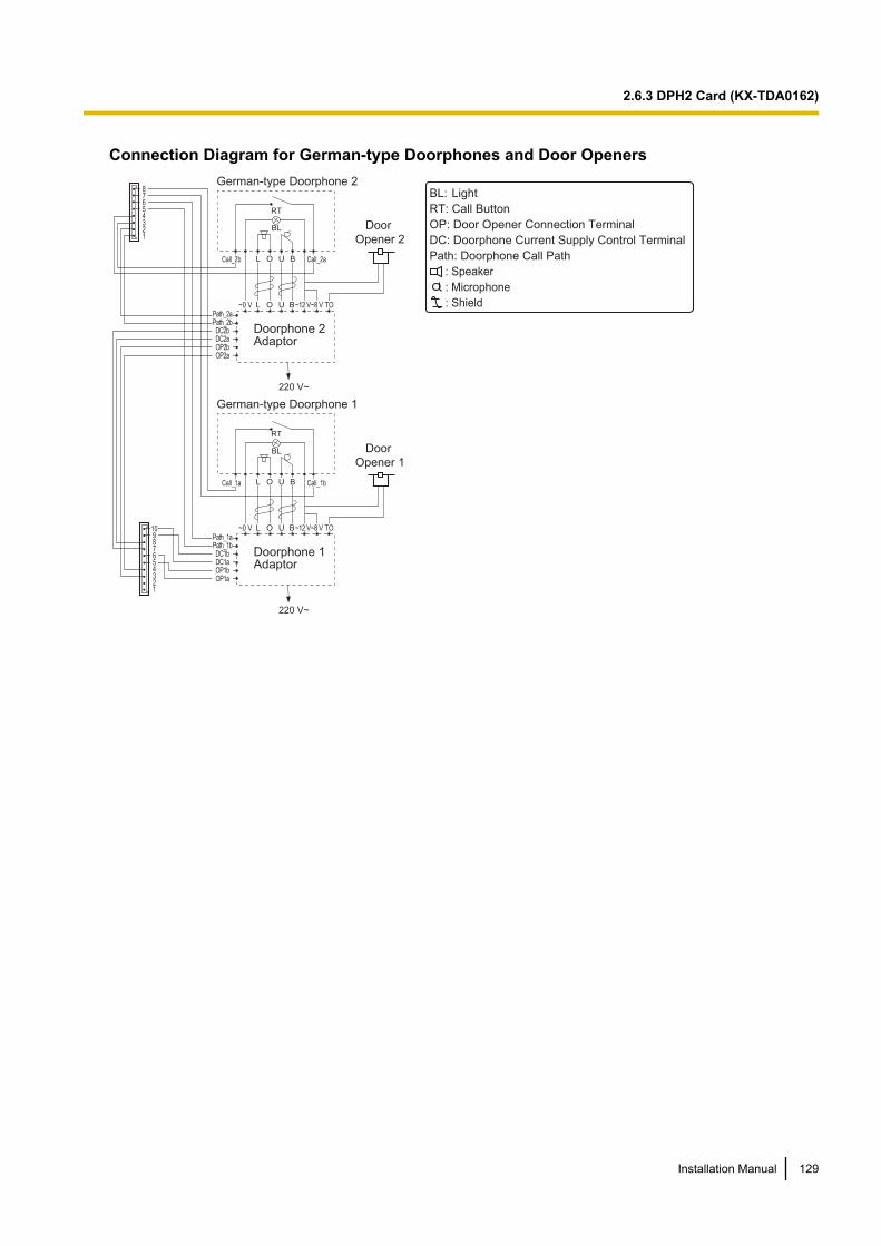
Connection Diagram for German-type Doorphones and Door OpenersGerman-type Doorphone 2
Doorphone 2Adaptor
220 V~
BL Door
Opener 2
RT
L O U B
Path_2aPath_2bDC2bDC2aOP2bOP2a
10987654321
Path_1aPath_1bDC1bDC1aOP1bOP1a
87654321
L O U B~12 V~8 V TO~0 V
BL: Light
RT: Call Button
OP: Door Opener Connection Terminal
DC: Doorphone Current Supply Control Terminal
Path: Doorphone Call Path
: Speaker
: Microphone
: Shield
Call_2b
Call_1a
Call_2a
Call_1b
Doorphone 1Adaptor
220 V~
BL Door
Opener 1
RT
L O U B
L O U B~12 V~8 V TO~0 V
German-type Doorphone 1
Installation Manual 129
2.6.3 DPH2 Card (KX-TDA0162)
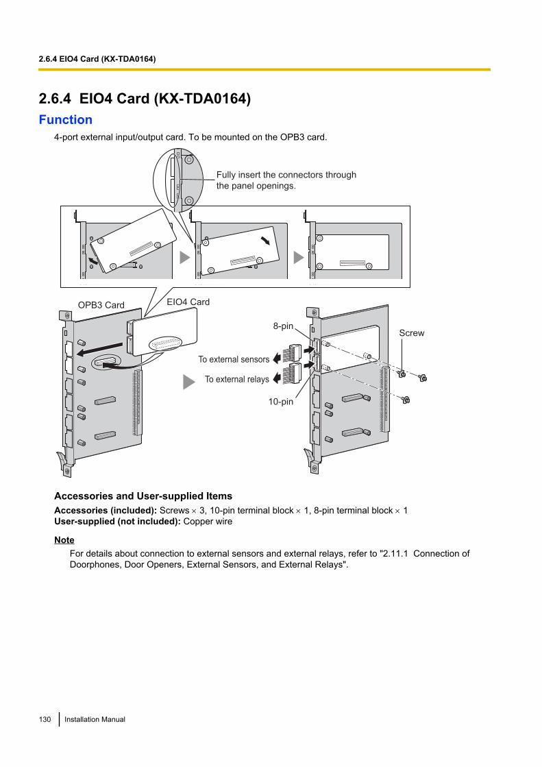
2.6.4 EIO4 Card (KX-TDA0164)Function
4-port external input/output card. To be mounted on the OPB3 card.
Fully insert the connectors through
the panel openings.
Screw
To external sensors
OPB3 Card EIO4 Card
To external relays
8-pin
10-pin
Accessories and User-supplied ItemsAccessories (included): Screws ´ 3, 10-pin terminal block ´ 1, 8-pin terminal block ´ 1User-supplied (not included): Copper wire
NoteFor details about connection to external sensors and external relays, refer to "2.11.1 Connection ofDoorphones, Door Openers, External Sensors, and External Relays".
130 Installation Manual
2.6.4 EIO4 Card (KX-TDA0164)
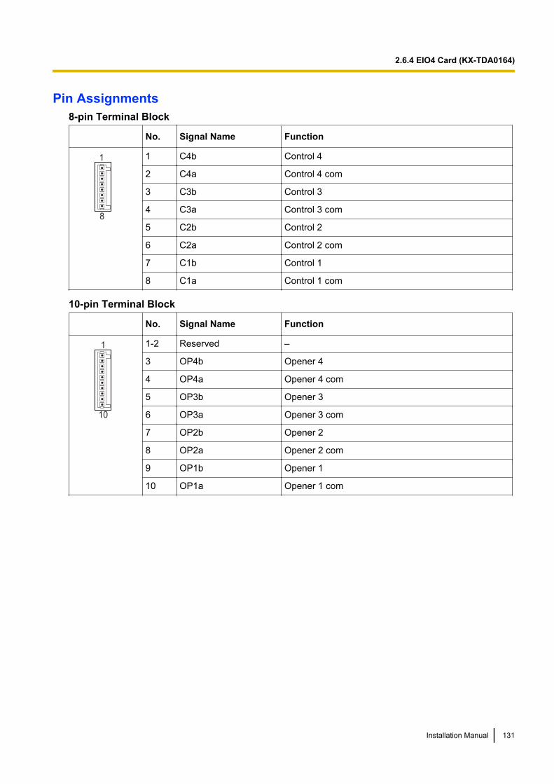
Pin Assignments8-pin Terminal Block
No. Signal Name Function
8
1 1 C4b Control 4
2 C4a Control 4 com
3 C3b Control 3
4 C3a Control 3 com
5 C2b Control 2
6 C2a Control 2 com
7 C1b Control 1
8 C1a Control 1 com
10-pin Terminal Block
No. Signal Name Function
10
1 1-2 Reserved –
3 OP4b Opener 4
4 OP4a Opener 4 com
5 OP3b Opener 3
6 OP3a Opener 3 com
7 OP2b Opener 2
8 OP2a Opener 2 com
9 OP1b Opener 1
10 OP1a Opener 1 com
Installation Manual 131
2.6.4 EIO4 Card (KX-TDA0164)
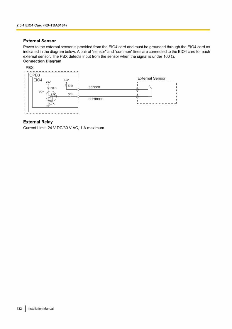
External SensorPower to the external sensor is provided from the EIO4 card and must be grounded through the EIO4 card asindicated in the diagram below. A pair of "sensor" and "common" lines are connected to the EIO4 card for eachexternal sensor. The PBX detects input from the sensor when the signal is under 100 W.Connection Diagram
External Sensor
sensor
common
I/O
EIO4
OPB3
PBX
+5V+5V
10K33
334.7K
4.7K
External RelayCurrent Limit: 24 V DC/30 V AC, 1 A maximum
132 Installation Manual
2.6.4 EIO4 Card (KX-TDA0164)
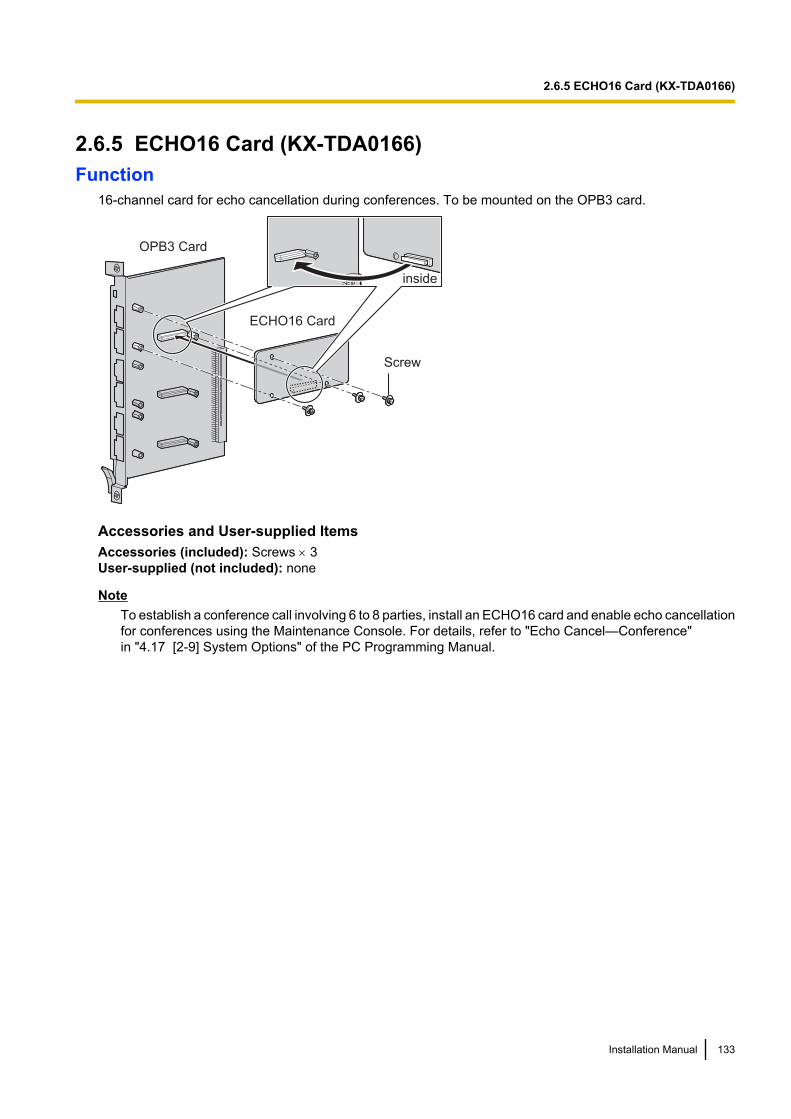
2.6.5 ECHO16 Card (KX-TDA0166)Function
16-channel card for echo cancellation during conferences. To be mounted on the OPB3 card.
OPB3 Card
Screw
inside
ECHO16 Card
Accessories and User-supplied ItemsAccessories (included): Screws ´ 3User-supplied (not included): none
NoteTo establish a conference call involving 6 to 8 parties, install an ECHO16 card and enable echo cancellationfor conferences using the Maintenance Console. For details, refer to "Echo Cancel—Conference"in "4.17 [2-9] System Options" of the PC Programming Manual.
Installation Manual 133
2.6.5 ECHO16 Card (KX-TDA0166)
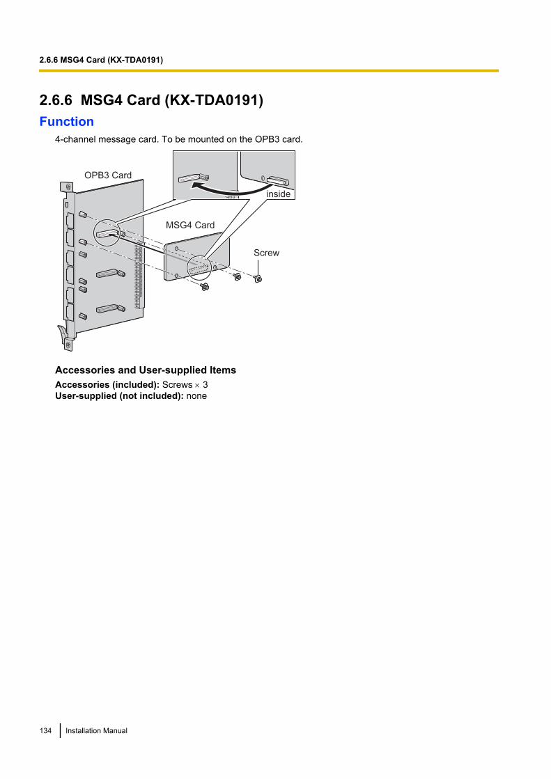
2.6.6 MSG4 Card (KX-TDA0191)Function
4-channel message card. To be mounted on the OPB3 card.
OPB3 Card
MSG4 Card
Screw
inside
Accessories and User-supplied ItemsAccessories (included): Screws ´ 3User-supplied (not included): none
134 Installation Manual
2.6.6 MSG4 Card (KX-TDA0191)
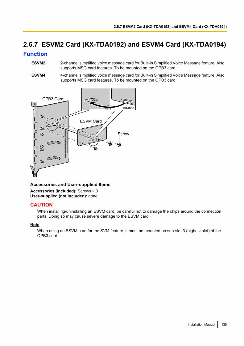
2.6.7 ESVM2 Card (KX-TDA0192) and ESVM4 Card (KX-TDA0194)Function
ESVM2: 2-channel simplified voice message card for Built-in Simplified Voice Message feature. Alsosupports MSG card features. To be mounted on the OPB3 card.
ESVM4: 4-channel simplified voice message card for Built-in Simplified Voice Message feature. Alsosupports MSG card features. To be mounted on the OPB3 card.
Screw
ESVM Card
OPB3 Card
inside
Accessories and User-supplied ItemsAccessories (included): Screws ´ 3User-supplied (not included): none
CAUTIONWhen installing/uninstalling an ESVM card, be careful not to damage the chips around the connectionparts. Doing so may cause severe damage to the ESVM card.
NoteWhen using an ESVM card for the SVM feature, it must be mounted on sub-slot 3 (highest slot) of theOPB3 card.
Installation Manual 135
2.6.7 ESVM2 Card (KX-TDA0192) and ESVM4 Card (KX-TDA0194)
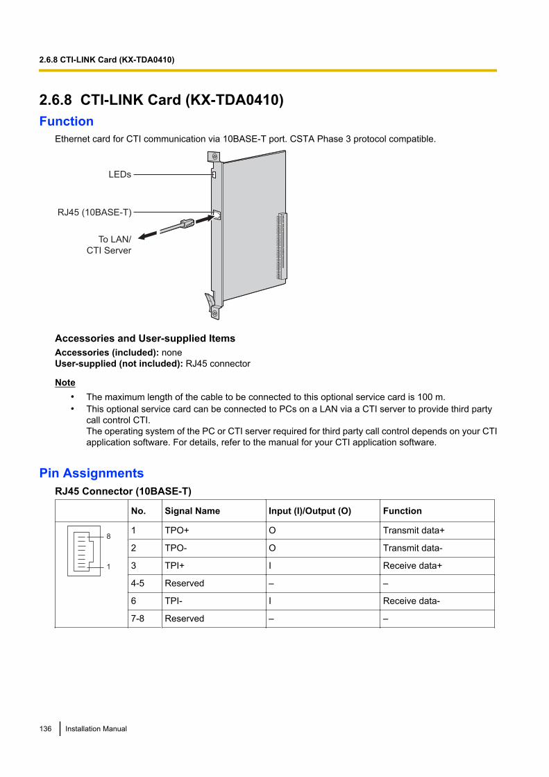
2.6.8 CTI-LINK Card (KX-TDA0410)Function
Ethernet card for CTI communication via 10BASE-T port. CSTA Phase 3 protocol compatible.
LEDs
RJ45 (10BASE-T)
To LAN/
CTI Server
Accessories and User-supplied ItemsAccessories (included): noneUser-supplied (not included): RJ45 connector
Note• The maximum length of the cable to be connected to this optional service card is 100 m.• This optional service card can be connected to PCs on a LAN via a CTI server to provide third party
call control CTI.The operating system of the PC or CTI server required for third party call control depends on your CTIapplication software. For details, refer to the manual for your CTI application software.
Pin AssignmentsRJ45 Connector (10BASE-T)
No. Signal Name Input (I)/Output (O) Function
8
1
1 TPO+ O Transmit data+
2 TPO- O Transmit data-
3 TPI+ I Receive data+
4-5 Reserved – –
6 TPI- I Receive data-
7-8 Reserved – –
136 Installation Manual
2.6.8 CTI-LINK Card (KX-TDA0410)
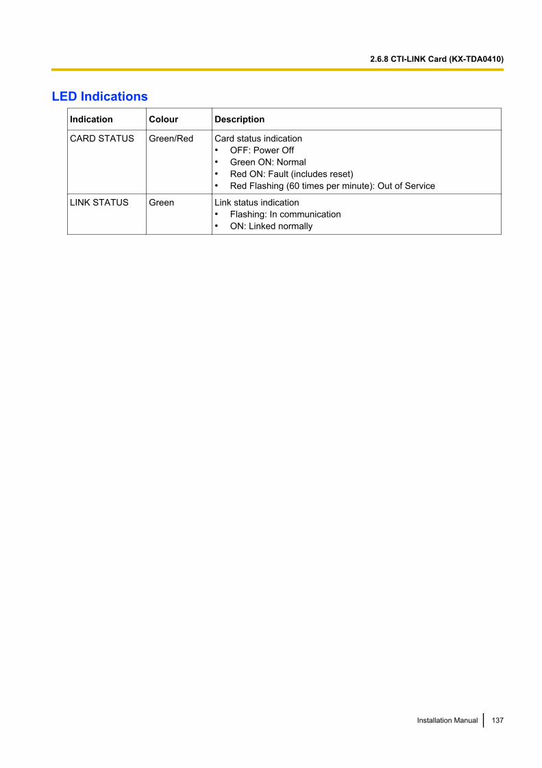
LED IndicationsIndication Colour Description
CARD STATUS Green/Red Card status indication• OFF: Power Off• Green ON: Normal• Red ON: Fault (includes reset)• Red Flashing (60 times per minute): Out of Service
LINK STATUS Green Link status indication• Flashing: In communication• ON: Linked normally
Installation Manual 137
2.6.8 CTI-LINK Card (KX-TDA0410)

2.7 Connection of Extensions
2.7.1 Maximum Cabling Distances of the Extension Wiring(Twisted Cable)
Cable Maximum Distance
ø 0.4 mm: 500 m
ø 0.5 mm: 720 m
ø 0.6 mm: 830 m
CAT 5: 720 m
Cable Maximum Distance
ø 0.4 mm: 500 m
ø 0.5 mm: 720 m
ø 0.6 mm: 830 m
CAT 5: 720 m
Cable Maximum Distance
ø 0.4 mm: 140 m
ø 0.5 mm: 229 m
ø 0.6 mm: 360 m
CAT 5: 229 m
Cable Maximum Distance
ø 0.4 mm: 698 m
ø 0.5 mm: 1128 m
ø 0.6 mm: 1798 m
CAT 5: 1128 m
Other PT and DSS Console
SLT
KX-T7600 Series DPT
Cable Maximum Distance
ø 0.4 mm: 222 m
ø 0.5 mm: 347 m
ø 0.6 mm: 500 m
CAT 5: 347 m
PT-interface CS
KX-DT300 Series DPT
NoteThe maximum cabling distance may vary depending on the conditions.
PT-interface CS DPT APT DSS Console SLT
DHLC8 Card ü ü ü ü ü
MSLC16, CSLC16,SLC16, SLC8 Cards ü
DLC16, DLC8 Cards ü ü ü
138 Installation Manual
2.7.1 Maximum Cabling Distances of the Extension Wiring (Twisted Cable)

"ü" indicates that the extension card supports the terminal.
Installation Manual 139
2.7.1 Maximum Cabling Distances of the Extension Wiring (Twisted Cable)

2.7.2 Parallel Connection of the ExtensionsAny SLT can be connected in parallel with an APT or a DPT as follows.
NoteIn addition to an SLT, an answering machine, a fax machine or a modem (PC) can be connected in parallelwith an APT or a DPT.
With APTFor parallel connection, eXtra Device Port (XDP) mode must be disabled for that port through systemprogramming. Refer to "1.11.9 Parallelled Telephone" and "2.1.1 Extension Port Configuration" in the FeatureGuide for further information.
To DHLC8 card
4-conductor wiring cord
Connect pins "T", "R", "D1",
and "D2".
2-conductor wiring cord
Connect pins "T" and "R".
SLTAPT
Modular
T-Adaptor
With DPTParallel mode or eXtra Device Port (XDP) mode can be selected through system programming.If XDP mode is enabled through system programming, parallel connection is not possible. Referto "1.11.9 Parallelled Telephone" and "2.1.1 Extension Port Configuration" in the Feature Guide for furtherinformation.
140 Installation Manual
2.7.2 Parallel Connection of the Extensions

Using a Modular T-AdaptorTo DHLC8 card
SLTDPT
Modular
T-Adaptor
4-conductor wiring cord
Connect pins "D1" and
"D2".
2-conductor wiring cord
Connect pins "T" and "R".
Using an EXtra Device PortWith KX-DT300 Series DPT (except KX-DT321)
To DHLC8 card
DPT SLT
To DHLC8 card
To SLT
2-conductor wiring cord
Connect pins "T" and "R".4-conductor wiring cord
Connect pins "T", "R",
"D1" and "D2".
TO MAIN UNIT/ PABX
TO TEL
Installation Manual 141
2.7.2 Parallel Connection of the Extensions
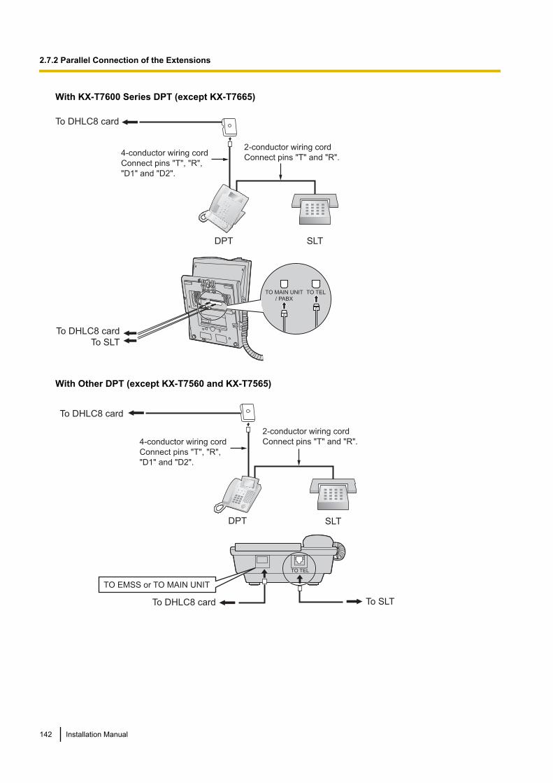
With KX-T7600 Series DPT (except KX-T7665)
To DHLC8 card
DPT SLT
To DHLC8 card
To SLT
2-conductor wiring cord
Connect pins "T" and "R".4-conductor wiring cord
Connect pins "T", "R",
"D1" and "D2".
TO MAIN UNIT/ PABX
TO TEL
With Other DPT (except KX-T7560 and KX-T7565)
To DHLC8 card
DPT SLT
To DHLC8 card To SLT
2-conductor wiring cord
Connect pins "T" and "R".4-conductor wiring cord
Connect pins "T", "R",
"D1" and "D2".
TO TEL
TO EMSS or TO MAIN UNIT
142 Installation Manual
2.7.2 Parallel Connection of the Extensions
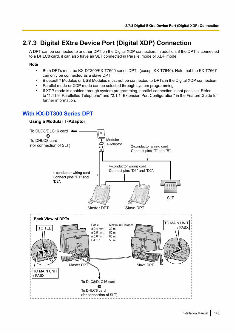
2.7.3 Digital EXtra Device Port (Digital XDP) ConnectionA DPT can be connected to another DPT on the Digital XDP connection. In addition, if the DPT is connectedto a DHLC8 card, it can also have an SLT connected in Parallel mode or XDP mode.
Note• Both DPTs must be KX-DT300/KX-T7600 series DPTs (except KX-T7640). Note that the KX-T7667
can only be connected as a slave DPT.• Bluetooth® Modules or USB Modules must not be connected to DPTs in the Digital XDP connection.• Parallel mode or XDP mode can be selected through system programming.• If XDP mode is enabled through system programming, parallel connection is not possible. Refer
to "1.11.9 Parallelled Telephone" and "2.1.1 Extension Port Configuration" in the Feature Guide forfurther information.
With KX-DT300 Series DPTUsing a Modular T-Adaptor
Slave DPTMaster DPT
Cable Maximum Distance
ø 0.4 mm: 30 m
ø 0.5 mm: 50 m
ø 0.6 mm: 60 m
CAT 5: 50 m
Back View of DPTs
To DLC8/DLC16 card
To DHLC8 card
(for connection of SLT)
TO MAIN UNIT
/ PABX
TO MAIN UNIT
/ PABX
TO TEL
To DLC8/DLC16 card
To DHLC8 card
(for connection of SLT)
4-conductor wiring cord
Connect pins "D1" and "D2".
Slave DPT
SLT
Master DPT
Modular
T-Adaptor
4-conductor wiring cord
Connect pins "D1" and
"D2".
2-conductor wiring cord
Connect pins "T" and "R".
Installation Manual 143
2.7.3 Digital EXtra Device Port (Digital XDP) Connection
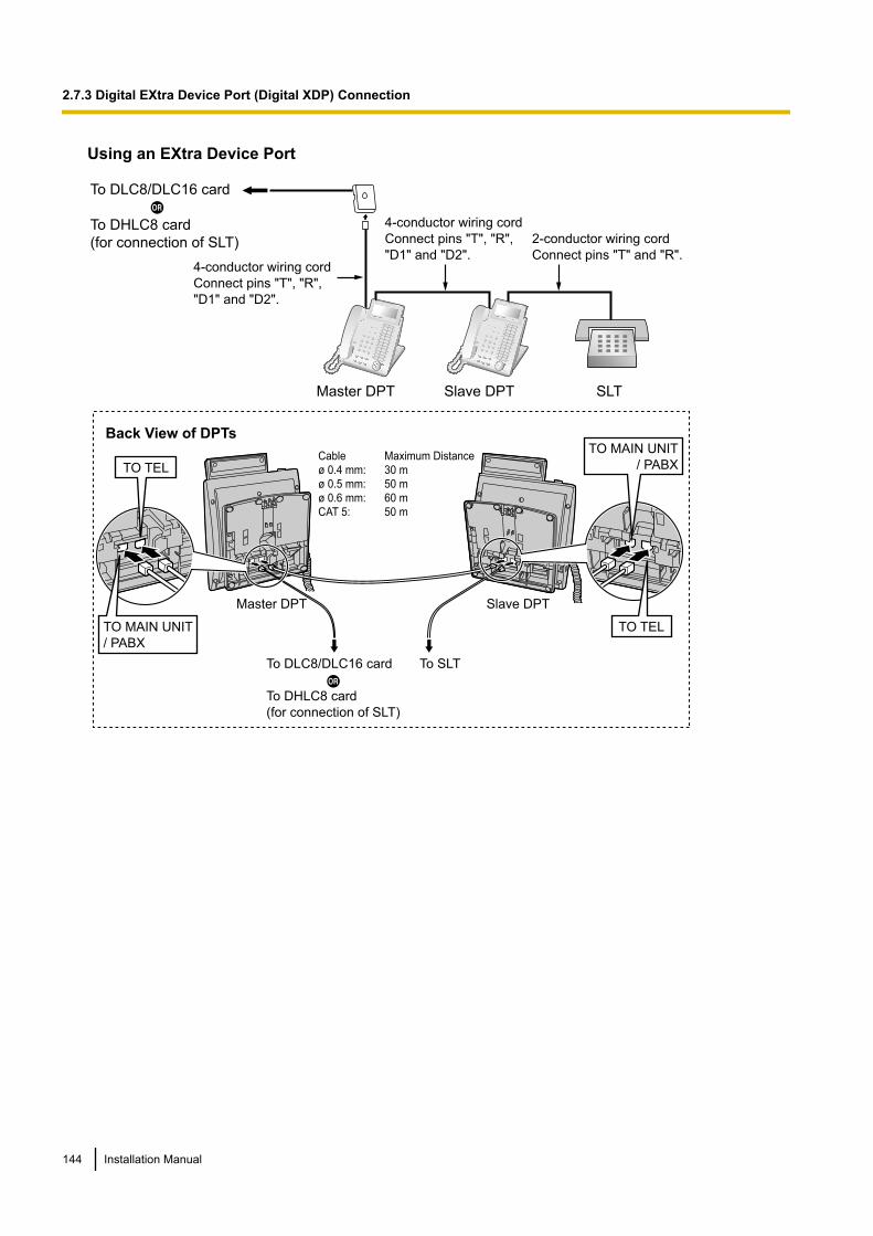
Using an EXtra Device Port
SLTMaster DPT Slave DPT
4-conductor wiring cord
Connect pins "T", "R",
"D1" and "D2".
2-conductor wiring cord
Connect pins "T" and "R".4-conductor wiring cord
Connect pins "T", "R",
"D1" and "D2".
To DLC8/DLC16 card
To DHLC8 card
(for connection of SLT)
To SLT
Slave DPTMaster DPT
Cable Maximum Distance
ø 0.4 mm: 30 m
ø 0.5 mm: 50 m
ø 0.6 mm: 60 m
CAT 5: 50 m
Back View of DPTs
To DLC8/DLC16 card
To DHLC8 card
(for connection of SLT)
TO MAIN UNIT
/ PABX
TO MAIN UNIT
/ PABX
TO TEL
TO TEL
144 Installation Manual
2.7.3 Digital EXtra Device Port (Digital XDP) Connection
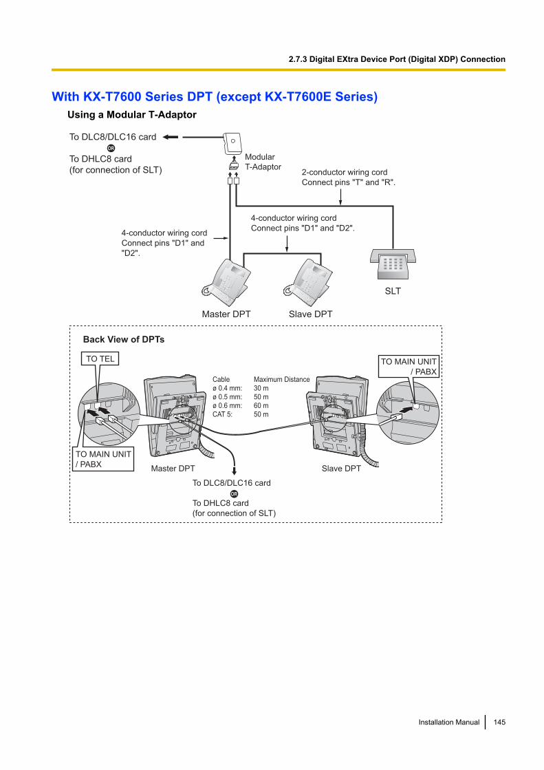
With KX-T7600 Series DPT (except KX-T7600E Series)Using a Modular T-Adaptor
To DLC8/DLC16 card
To DHLC8 card
(for connection of SLT)
4-conductor wiring cord
Connect pins "D1" and "D2".
Slave DPT
SLT
Master DPT
Modular
T-Adaptor
4-conductor wiring cord
Connect pins "D1" and
"D2".
2-conductor wiring cord
Connect pins "T" and "R".
Slave DPTMaster DPT
TO MAIN UNIT
/ PABX
TO TEL
TO MAIN UNIT
/ PABX
Cable Maximum Distance
ø 0.4 mm: 30 m
ø 0.5 mm: 50 m
ø 0.6 mm: 60 m
CAT 5: 50 m
Back View of DPTs
To DLC8/DLC16 card
To DHLC8 card
(for connection of SLT)
Installation Manual 145
2.7.3 Digital EXtra Device Port (Digital XDP) Connection
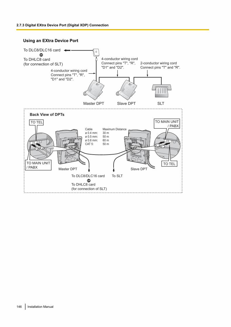
Using an EXtra Device Port
SLTMaster DPT Slave DPT
4-conductor wiring cord
Connect pins "T", "R",
"D1" and "D2".
2-conductor wiring cord
Connect pins "T" and "R".4-conductor wiring cord
Connect pins "T", "R",
"D1" and "D2".
Slave DPTMaster DPT
To SLT
TO MAIN UNIT
/ PABX
TO TEL
TO TEL
TO MAIN UNIT
/ PABX
Cable Maximum Distance
ø 0.4 mm: 30 m
ø 0.5 mm: 50 m
ø 0.6 mm: 60 m
CAT 5: 50 m
Back View of DPTs
To DLC8/DLC16 card
To DHLC8 card
(for connection of SLT)
To DLC8/DLC16 card
To DHLC8 card
(for connection of SLT)
146 Installation Manual
2.7.3 Digital EXtra Device Port (Digital XDP) Connection
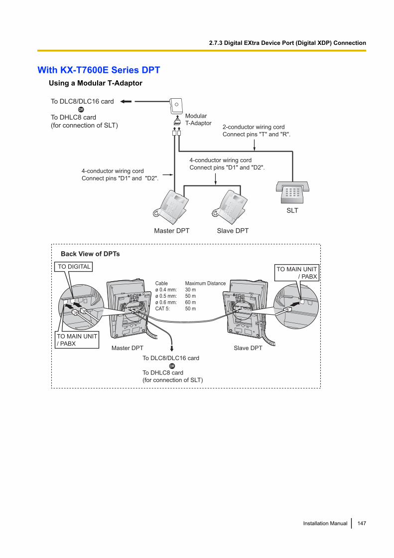
With KX-T7600E Series DPTUsing a Modular T-Adaptor
4-conductor wiring cord
Connect pins "D1" and "D2".
Slave DPT
SLT
Master DPT
Modular
T-Adaptor
4-conductor wiring cord
Connect pins "D1" and "D2".
2-conductor wiring cord
Connect pins "T" and "R".
Slave DPTMaster DPT
TO MAIN UNIT
/ PABX
TO DIGITAL
TO MAIN UNIT
/ PABX
Cable Maximum Distance
ø 0.4 mm: 30 m
ø 0.5 mm: 50 m
ø 0.6 mm: 60 m
CAT 5: 50 m
Back View of DPTs
To DLC8/DLC16 card
To DHLC8 card
(for connection of SLT)
To DLC8/DLC16 card
To DHLC8 card
(for connection of SLT)
Installation Manual 147
2.7.3 Digital EXtra Device Port (Digital XDP) Connection
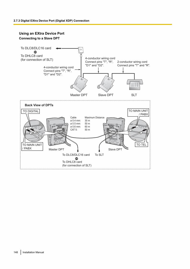
Using an EXtra Device PortConnecting to a Slave DPT
SLTMaster DPT Slave DPT
4-conductor wiring cord
Connect pins "T", "R",
"D1" and "D2".
2-conductor wiring cord
Connect pins "T" and "R".4-conductor wiring cord
Connect pins "T", "R",
"D1" and "D2".
Slave DPTMaster DPT
To SLT
TO MAIN UNIT
/ PABX
TO TEL
TO DIGITAL
TO MAIN UNIT
/ PABX
Cable Maximum Distance
ø 0.4 mm: 30 m
ø 0.5 mm: 50 m
ø 0.6 mm: 60 m
CAT 5: 50 m
Back View of DPTs
To DLC8/DLC16 card
To DHLC8 card
(for connection of SLT)
To DLC8/DLC16 card
To DHLC8 card
(for connection of SLT)
148 Installation Manual
2.7.3 Digital EXtra Device Port (Digital XDP) Connection
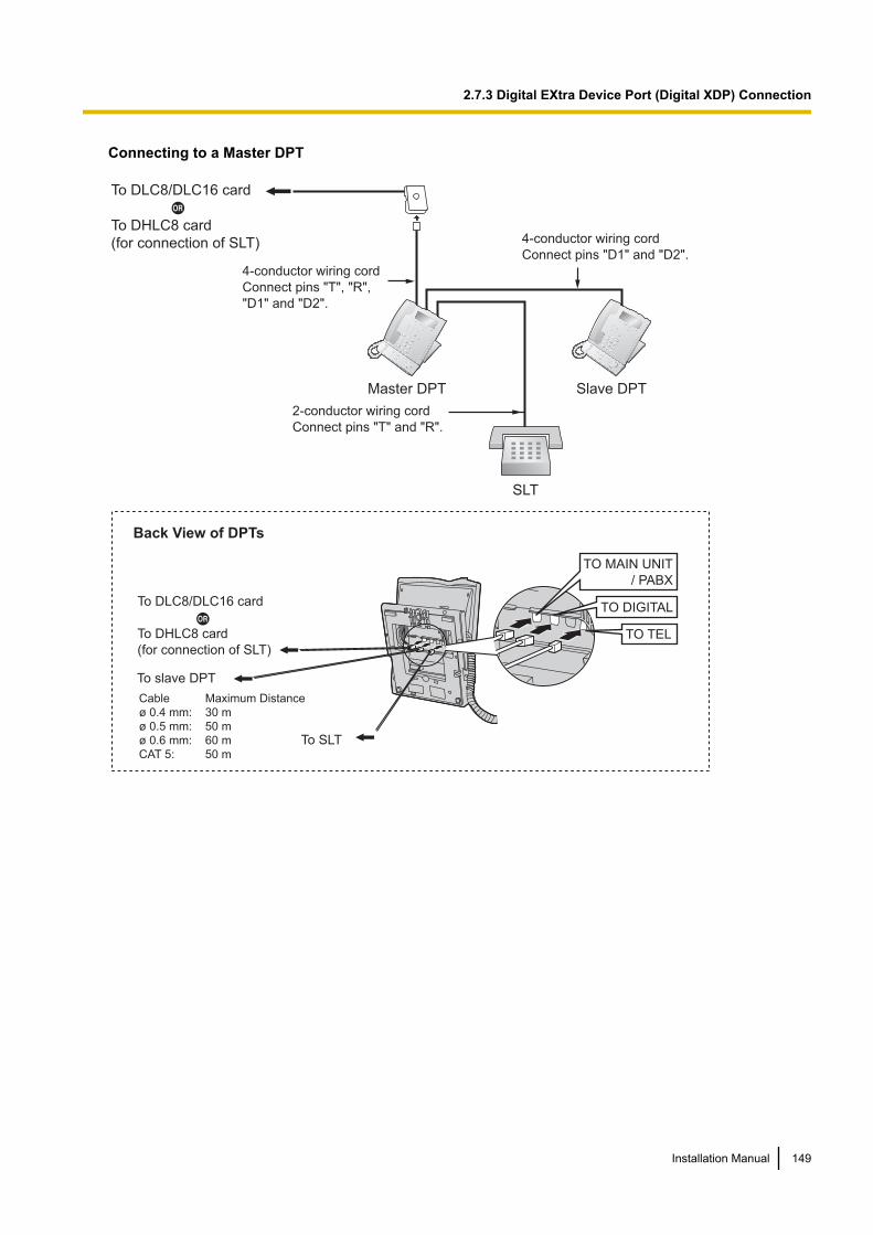
Connecting to a Master DPT
SLT
To slave DPT
To SLT
Master DPT Slave DPT
4-conductor wiring cord
Connect pins "D1" and "D2".
2-conductor wiring cord
Connect pins "T" and "R".
4-conductor wiring cord
Connect pins "T", "R",
"D1" and "D2".
TO DIGITAL
TO MAIN UNIT
/ PABX
TO TEL
Back View of DPTs
Cable Maximum Distance
ø 0.4 mm: 30 m
ø 0.5 mm: 50 m
ø 0.6 mm: 60 m
CAT 5: 50 m
To DLC8/DLC16 card
To DHLC8 card
(for connection of SLT)
To DLC8/DLC16 card
To DHLC8 card
(for connection of SLT)
Installation Manual 149
2.7.3 Digital EXtra Device Port (Digital XDP) Connection
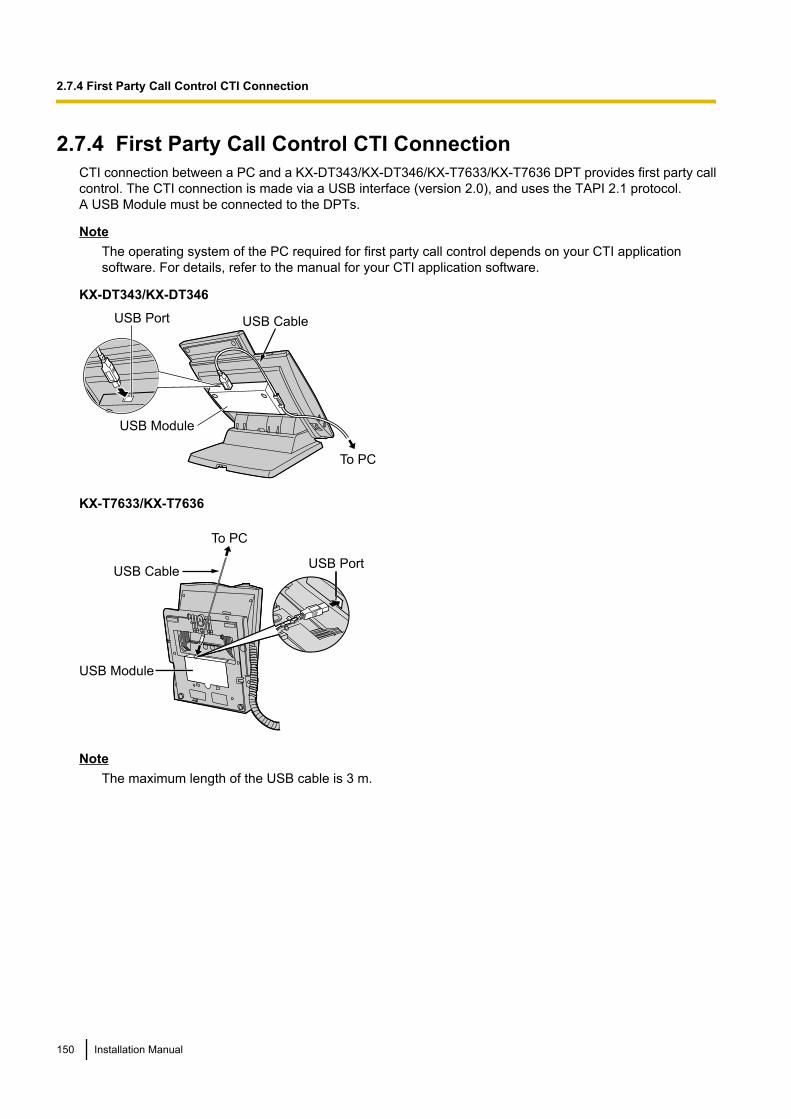
2.7.4 First Party Call Control CTI ConnectionCTI connection between a PC and a KX-DT343/KX-DT346/KX-T7633/KX-T7636 DPT provides first party callcontrol. The CTI connection is made via a USB interface (version 2.0), and uses the TAPI 2.1 protocol.A USB Module must be connected to the DPTs.
NoteThe operating system of the PC required for first party call control depends on your CTI applicationsoftware. For details, refer to the manual for your CTI application software.
KX-DT343/KX-DT346
USB Port USB Cable
USB Module
To PC
KX-T7633/KX-T7636
USB Cable
To PC
ULL
USB Port
USB Module
NoteThe maximum length of the USB cable is 3 m.
150 Installation Manual
2.7.4 First Party Call Control CTI Connection

2.8 Connection of DECT Portable Stations
2.8.1 OverviewRequired Equipment and Maximum Number of Calls
CSs determine the area covered by the wireless system. The number of calls that can be made simultaneouslythrough each CS varies depending on the model, as follows:
CS Connection Card Maximum Calls Compatible PSs
KX-TDA0158CE DHLC/DLC 8 • KX-TCA155• KX-TCA255• KX-TCA256• KX-TCA355• KX-TD7590• KX-TD7580
KX-TDA0141CE DHLC/DLC 2
KX-TDA0142CE CSIF 4
NoticeThe CSs for DECT are for connection to specified Panasonic PBXs only.
NoteFor more details about the PS, refer to the Operating Instructions of the PS.
Required Distances between EquipmentCAUTION
Maintain the distances listed below between equipment in order to prevent noise, interference or thedisconnection of a conversation. (The distance may vary depending on the environment.)
Equipment Distance
CS and office equipment such as a computer, telex, faxmachine, etc., or microwaves
More than 2 m
CS and PS More than 1 m
Each PS More than 0.5 m
PBX and CS More than 2 m
NoticeToo many CSs in a small area can cause problems due to conflicts over which signal channels each CScan use. Ideally, CSs should be a minimum of 25 m to 40 m apart.However, the required distance between CSs may vary depending on the environment of the installationsite and conditions in which the wireless system is used. Conduct the site survey to determine theappropriate distance.
RF SpecificationItem Description
Radio Access Method MultiCarrier TDMA-TDD
Installation Manual 151
2.8.1 Overview
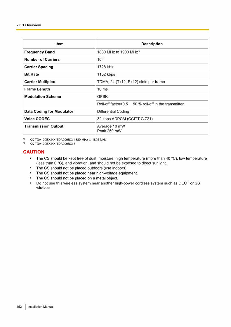
Item Description
Frequency Band 1880 MHz to 1900 MHz*1
Number of Carriers 10*2
Carrier Spacing 1728 kHz
Bit Rate 1152 kbps
Carrier Multiplex TDMA, 24 (Tx12, Rx12) slots per frame
Frame Length 10 ms
Modulation Scheme GFSK
Roll-off factor=0.5 50 % roll-off in the transmitter
Data Coding for Modulator Differential Coding
Voice CODEC 32 kbps ADPCM (CCITT G.721)
Transmission Output Average 10 mWPeak 250 mW
*1 KX-TDA100BX/KX-TDA200BX: 1880 MHz to 1895 MHz*2 KX-TDA100BX/KX-TDA200BX: 8
CAUTION• The CS should be kept free of dust, moisture, high temperature (more than 40 °C), low temperature
(less than 0 °C), and vibration, and should not be exposed to direct sunlight.• The CS should not be placed outdoors (use indoors).• The CS should not be placed near high-voltage equipment.• The CS should not be placed on a metal object.• Do not use this wireless system near another high-power cordless system such as DECT or SS
wireless.
152 Installation Manual
2.8.1 Overview
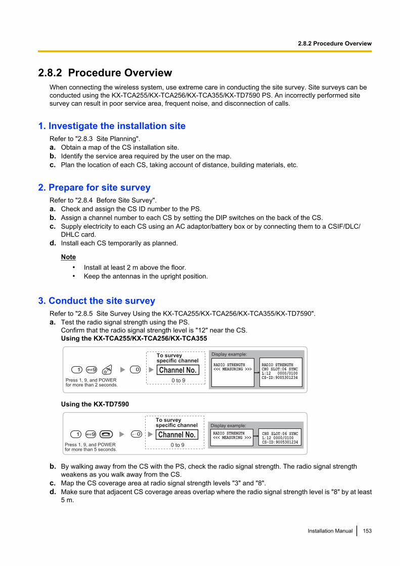
2.8.2 Procedure OverviewWhen connecting the wireless system, use extreme care in conducting the site survey. Site surveys can beconducted using the KX-TCA255/KX-TCA256/KX-TCA355/KX-TD7590 PS. An incorrectly performed sitesurvey can result in poor service area, frequent noise, and disconnection of calls.
1. Investigate the installation siteRefer to "2.8.3 Site Planning".a. Obtain a map of the CS installation site.b. Identify the service area required by the user on the map.c. Plan the location of each CS, taking account of distance, building materials, etc.
2. Prepare for site surveyRefer to "2.8.4 Before Site Survey".a. Check and assign the CS ID number to the PS.b. Assign a channel number to each CS by setting the DIP switches on the back of the CS.c. Supply electricity to each CS using an AC adaptor/battery box or by connecting them to a CSIF/DLC/
DHLC card.d. Install each CS temporarily as planned.
Note• Install at least 2 m above the floor.• Keep the antennas in the upright position.
3. Conduct the site surveyRefer to "2.8.5 Site Survey Using the KX-TCA255/KX-TCA256/KX-TCA355/KX-TD7590".a. Test the radio signal strength using the PS.
Confirm that the radio signal strength level is "12" near the CS.Using the KX-TCA255/KX-TCA256/KX-TCA355
Display example:
RADIO STRENGTH<<< MEASURING >>>
RADIO STRENGTHCH0 SLOT:06 SYNCL:12 0000/0100CS-ID:9005301234
Press 1, 9, and POWERfor more than 2 seconds.
1 99 0
0 to 9
Channel No.
To surveyspecific channel
Using the KX-TD7590
Display example:
RADIO STRENGTH<<< MEASURING >>>
CH0 SLOT:06 SYNCL:12 0000/0100CS-ID:9005301234
Press 1, 9, and POWERfor more than 5 seconds.
1 99 0
0 to 9
Channel No.
To surveyspecific channel
b. By walking away from the CS with the PS, check the radio signal strength. The radio signal strengthweakens as you walk away from the CS.
c. Map the CS coverage area at radio signal strength levels "3" and "8".d. Make sure that adjacent CS coverage areas overlap where the radio signal strength level is "8" by at least
5 m.
Installation Manual 153
2.8.2 Procedure Overview
e. Make sure that the radio signal strength level is greater than "3" at any location within the service arearequired by the user.
4. Finish the site surveyRefer to "2.8.6 After Site Survey".a. Turn off the PS.b. Stop supplying power, and return all DIP switches of each CS to the OFF position.
5. Connect the CS and PS to the PBX and test the operationRefer to "2.8.7 Connecting a Cell Station to the PBX".a. Connect the CSs to the PBX.b. Register the PSs to the PBX.c. Walk around the service area while having a conversation using a registered PS. If noise is frequent or
conversations disconnect, relocate the CSs or install an additional CS.
6. Mount the CS on the wallRefer to "2.8.8 Wall Mounting".a. If there are no problems in testing, mount the CS on the wall.
154 Installation Manual
2.8.2 Procedure Overview

2.8.3 Site PlanningChoosing the best site for the CS requires careful planning and testing of essential areas. The best locationmay not always be convenient for installation. Read the following information before installing the unit.
Understanding Radio WavesCharacteristics of Radio WavesThe transmission of radio waves and the CS coverage area depend on the structure and materials of thebuilding.Office equipment, such as computers and fax machines, can interfere with radio waves. Such equipment maycreate noise or interfere with the performance of the PS.The illustration below shows the special transmitting patterns of radio waves.1. Radio waves are reflected by objects made of materials such as metal.2. Radio waves are diffracted by objects such as metallic columns.3. Radio waves penetrate objects made of materials such as glass.
CS
Column
3. Penetration
2. Diffraction
1. Reflection
Relationships Between Radio Waves and Building Structure and Materials• The CS coverage area is affected more by the building materials and their thickness than the number of
obstacles.• Radio waves tend to be reflected or diffracted by conductive objects and rarely penetrate them.• Radio waves tend to penetrate insulated objects and are rarely reflected by them.• Radio waves penetrate thin objects more than thick objects.• The table below shows the transmission tendency of radio waves when they reach objects made from
various materials.
Installation Manual 155
2.8.3 Site Planning
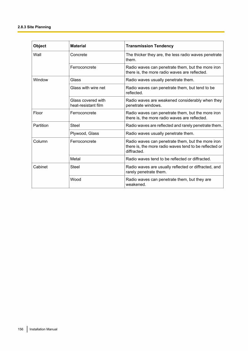
Object Material Transmission Tendency
Wall Concrete The thicker they are, the less radio waves penetratethem.
Ferroconcrete Radio waves can penetrate them, but the more ironthere is, the more radio waves are reflected.
Window Glass Radio waves usually penetrate them.
Glass with wire net Radio waves can penetrate them, but tend to bereflected.
Glass covered withheat-resistant film
Radio waves are weakened considerably when theypenetrate windows.
Floor Ferroconcrete Radio waves can penetrate them, but the more ironthere is, the more radio waves are reflected.
Partition Steel Radio waves are reflected and rarely penetrate them.
Plywood, Glass Radio waves usually penetrate them.
Column Ferroconcrete Radio waves can penetrate them, but the more ironthere is, the more radio waves tend to be reflected ordiffracted.
Metal Radio waves tend to be reflected or diffracted.
Cabinet Steel Radio waves are usually reflected or diffracted, andrarely penetrate them.
Wood Radio waves can penetrate them, but they areweakened.
156 Installation Manual
2.8.3 Site Planning
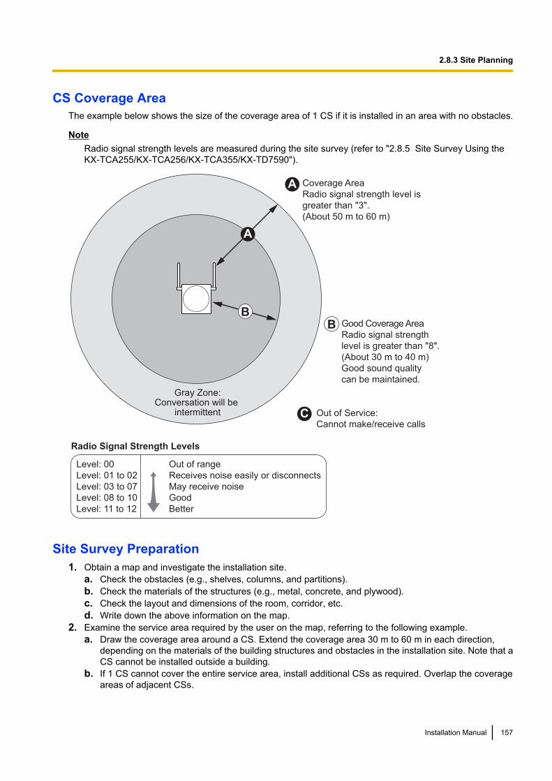
CS Coverage AreaThe example below shows the size of the coverage area of 1 CS if it is installed in an area with no obstacles.
NoteRadio signal strength levels are measured during the site survey (refer to "2.8.5 Site Survey Using theKX-TCA255/KX-TCA256/KX-TCA355/KX-TD7590").
Gray Zone:Conversation will be
intermittent
Coverage Area
Radio signal strength level is
greater than "3".
(About 50 m to 60 m)
Good Coverage Area
Radio signal strength
level is greater than "8".
(About 30 m to 40 m)
Good sound quality
can be maintained.
Out of Service:
Cannot make/receive calls
A
B
A
B
Radio Signal Strength Levels
C
Out of range
Receives noise easily or disconnects
May receive noise
Good
Better
Level: 00
Level: 01 to 02
Level: 03 to 07
Level: 08 to 10
Level: 11 to 12
Site Survey Preparation1. Obtain a map and investigate the installation site.
a. Check the obstacles (e.g., shelves, columns, and partitions).b. Check the materials of the structures (e.g., metal, concrete, and plywood).c. Check the layout and dimensions of the room, corridor, etc.d. Write down the above information on the map.
2. Examine the service area required by the user on the map, referring to the following example.a. Draw the coverage area around a CS. Extend the coverage area 30 m to 60 m in each direction,
depending on the materials of the building structures and obstacles in the installation site. Note that aCS cannot be installed outside a building.
b. If 1 CS cannot cover the entire service area, install additional CSs as required. Overlap the coverageareas of adjacent CSs.
Installation Manual 157
2.8.3 Site Planning

Where CS coverage areas overlap, the PS will start call handover to the next CS if the signal from oneCS becomes weak. However, if a PS moves away from a CS and there are no CSs available forhandover, the PS may go out of range and the call could be lost.
Example: Installing in a Room Separated by Interior WallsThings to take note of:• The room is separated by interior walls.• The room is surrounded by concrete walls.CS installation plan:• The coverage area of each CS will not extend as far as when there are no obstacles, because the radio
signals will be weakened by separating walls. Therefore, you will need 5 CSs to cover the entire room.
70 m
150 m
CS no. 5
CS no. 1
CS no. 2
CS no. 4CS no. 3
158 Installation Manual
2.8.3 Site Planning
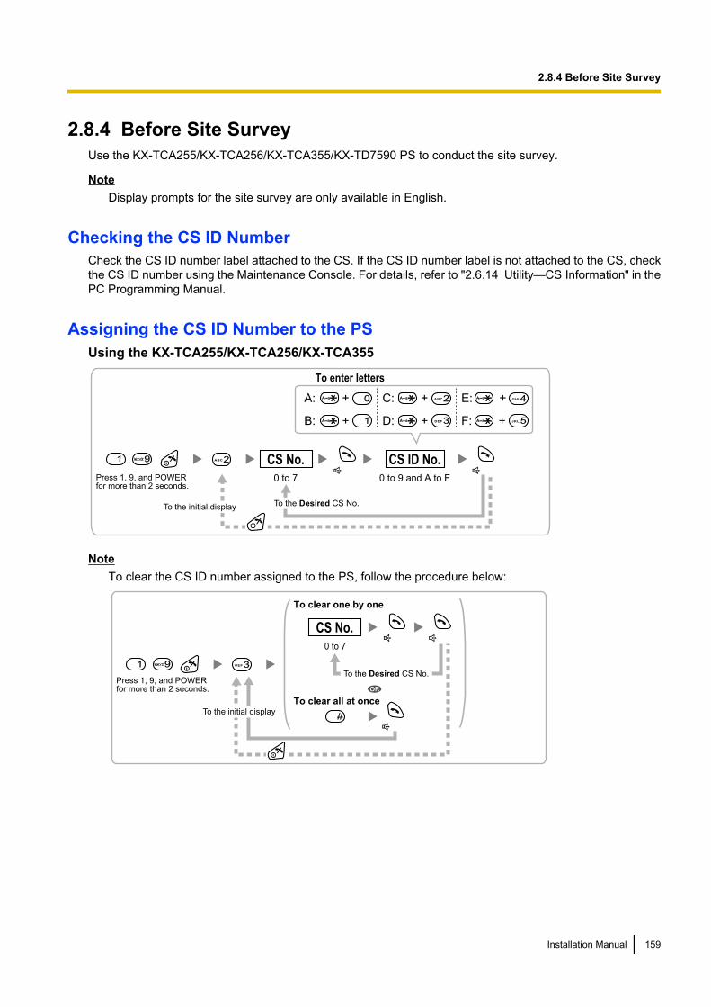
2.8.4 Before Site SurveyUse the KX-TCA255/KX-TCA256/KX-TCA355/KX-TD7590 PS to conduct the site survey.
NoteDisplay prompts for the site survey are only available in English.
Checking the CS ID NumberCheck the CS ID number label attached to the CS. If the CS ID number label is not attached to the CS, checkthe CS ID number using the Maintenance Console. For details, refer to "2.6.14 Utility—CS Information" in thePC Programming Manual.
Assigning the CS ID Number to the PSUsing the KX-TCA255/KX-TCA256/KX-TCA355
Press 1, 9, and POWERfor more than 2 seconds.
0 to 7 0 to 9 and A to F
CS No. CS ID No.1 99 2ABC
To enter letters
A: + C: + E: +
B: + D: + F: +
To the initial display To the Desired CS No.
3DEF
4GHI0
1 5JKL
2ABC
NoteTo clear the CS ID number assigned to the PS, follow the procedure below:
Press 1, 9, and POWERfor more than 2 seconds.
0 to 7
CS No.
1 99 3DEF
To the Desired CS No.
OR
#
To clear one by one
To clear all at onceTo the initial display
Installation Manual 159
2.8.4 Before Site Survey

Using the KX-TD7590
Press 1, 9, and POWERfor more than 5 seconds.
0 to 7 0 to 9 and A to F
CS No. CS ID No.1 99 2ABC
To enter letters
F1
F2
F3
INT'
OKA: C: E:
B: D: F:
To the initial display To the Desired CS No.
NoteTo clear the CS ID number assigned to the PS, follow the procedure below:
Press 1, 9, and POWERfor more than 2 seconds.
0 to 7
CS No.
1 99 3DEF
To the Desired CS No.
OR
#
To clear one by one
To clear all at onceTo the initial display
160 Installation Manual
2.8.4 Before Site Survey

Setting and Installing the CS Temporarily for Site Survey1. Switch the Radio Signal Test switch from OFF to ON.2. Set the channel number switches as desired.3. Set the Power Supply Select switch as desired (KX-TDA0158CE only).
KX-TDA0158CE
6
5
4
3
2
1
4
3
2
1
4
3
2
1
4
3
2
1
4
3
2
1
4
3
2
1
4
3
2
1
4
3
2
1
4
3
2
1
4
3
2
1
4
3
2
1
DIP Switch
Radio Signal Test Switch
Power Supply Select Switch
Channel Number Switch
Channel 1 Channel 2 Channel 3 Channel 4 Channel 5 Channel 6 Channel 7 Channel 8 Channel 9Channel 0
ON OFF
ON:
OFF: From the PBX
From the AC Adaptor or
Battery Box
Installation Manual 161
2.8.4 Before Site Survey
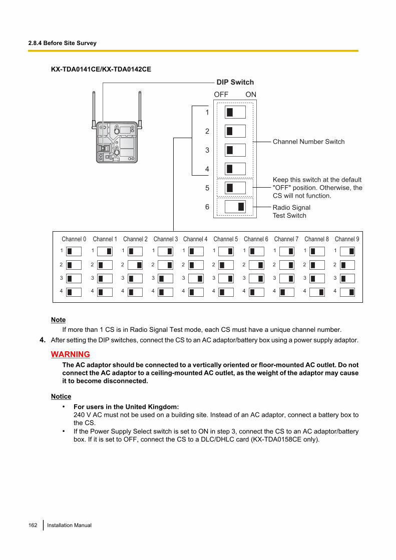
KX-TDA0141CE/KX-TDA0142CE
Channel Number Switch
Channel 1 Channel 2 Channel 3 Channel 4 Channel 5 Channel 6 Channel 7 Channel 8 Channel 9
1
2
3
4
1
2
3
4
1
2
3
4
1
2
3
4
1
2
3
4
1
2
3
4
1
2
3
4
1
2
3
4
1
2
3
4
DIP Switch
1
2
3
4
5
6
OFF ON
Radio Signal
Test Switch
Channel 0
1
2
3
4
Keep this switch at the default
"OFF" position. Otherwise, the
CS will not function.
NoteIf more than 1 CS is in Radio Signal Test mode, each CS must have a unique channel number.
4. After setting the DIP switches, connect the CS to an AC adaptor/battery box using a power supply adaptor.
WARNINGThe AC adaptor should be connected to a vertically oriented or floor-mounted AC outlet. Do notconnect the AC adaptor to a ceiling-mounted AC outlet, as the weight of the adaptor may causeit to become disconnected.
Notice• For users in the United Kingdom:
240 V AC must not be used on a building site. Instead of an AC adaptor, connect a battery box tothe CS.
• If the Power Supply Select switch is set to ON in step 3, connect the CS to an AC adaptor/batterybox. If it is set to OFF, connect the CS to a DLC/DHLC card (KX-TDA0158CE only).
162 Installation Manual
2.8.4 Before Site Survey
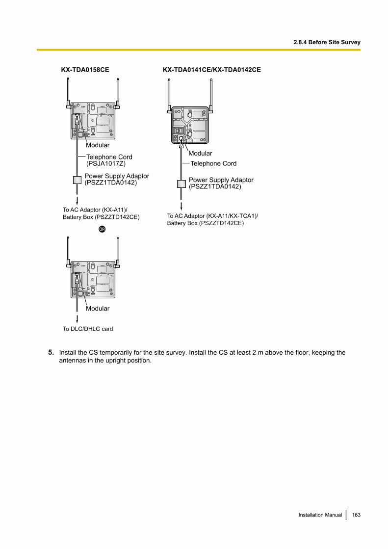
KX-TDA0158CE
Modular
To AC Adaptor (KX-A11)/
Battery Box (PSZZTD142CE)
To DLC/DHLC card
Power Supply Adaptor(PSZZ1TDA0142)
Modular
Telephone Cord(PSJA1017Z)
KX-TDA0141CE/KX-TDA0142CE
To AC Adaptor (KX-A11/KX-TCA1)/
Battery Box (PSZZTD142CE)
Power Supply Adaptor(PSZZ1TDA0142)
Modular
Telephone Cord
5. Install the CS temporarily for the site survey. Install the CS at least 2 m above the floor, keeping theantennas in the upright position.
Installation Manual 163
2.8.4 Before Site Survey
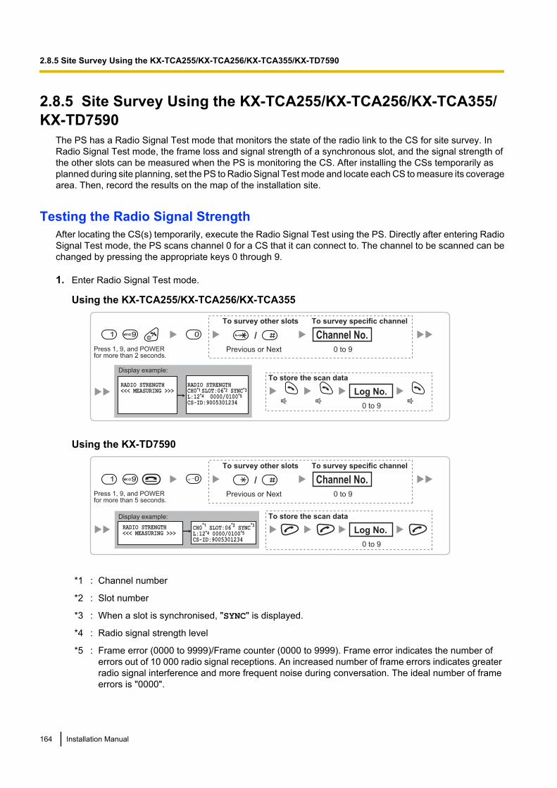
2.8.5 Site Survey Using the KX-TCA255/KX-TCA256/KX-TCA355/KX-TD7590
The PS has a Radio Signal Test mode that monitors the state of the radio link to the CS for site survey. InRadio Signal Test mode, the frame loss and signal strength of a synchronous slot, and the signal strength ofthe other slots can be measured when the PS is monitoring the CS. After installing the CSs temporarily asplanned during site planning, set the PS to Radio Signal Test mode and locate each CS to measure its coveragearea. Then, record the results on the map of the installation site.
Testing the Radio Signal StrengthAfter locating the CS(s) temporarily, execute the Radio Signal Test using the PS. Directly after entering RadioSignal Test mode, the PS scans channel 0 for a CS that it can connect to. The channel to be scanned can bechanged by pressing the appropriate keys 0 through 9.
1. Enter Radio Signal Test mode.
Using the KX-TCA255/KX-TCA256/KX-TCA355
0 to 9
Log No.
To store the scan data
Press 1, 9, and POWERfor more than 2 seconds.
1 99
Previous or Next 0 to 9
Channel No.
To survey other slots To survey specific channel
/
RADIO STRENGTH<<< MEASURING >>>
RADIO STRENGTHCH0*1 SLOT:06*2 SYNC*3
L:12*4 0000/0100*5
CS-ID:9005301234
0
Display example:
Using the KX-TD7590
Display example:
RADIO STRENGTH<<< MEASURING >>>
CH0*1 SLOT:06
*2 SYNC
*3
L:12*4 0000/0100*5
CS-ID:90053012340 to 9
Log No.
To store the scan data
Press 1, 9, and POWERfor more than 5 seconds.
1 99 0
Previous or Next 0 to 9
Channel No.
To survey other slots To survey specific channel
/
*1 : Channel number
*2 : Slot number
*3 : When a slot is synchronised, "SYNC" is displayed.
*4 : Radio signal strength level
*5 : Frame error (0000 to 9999)/Frame counter (0000 to 9999). Frame error indicates the number oferrors out of 10 000 radio signal receptions. An increased number of frame errors indicates greaterradio signal interference and more frequent noise during conversation. The ideal number of frameerrors is "0000".
164 Installation Manual
2.8.5 Site Survey Using the KX-TCA255/KX-TCA256/KX-TCA355/KX-TD7590
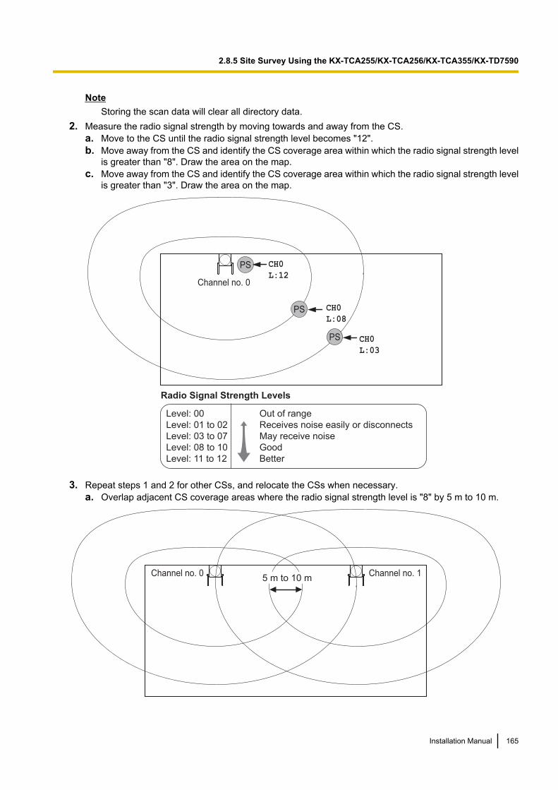
NoteStoring the scan data will clear all directory data.
2. Measure the radio signal strength by moving towards and away from the CS.a. Move to the CS until the radio signal strength level becomes "12".b. Move away from the CS and identify the CS coverage area within which the radio signal strength level
is greater than "8". Draw the area on the map.c. Move away from the CS and identify the CS coverage area within which the radio signal strength level
is greater than "3". Draw the area on the map.
Channel no. 0
PS
PS
PS CH0
L:03
CH0
L:12
Radio Signal Strength Levels
Out of range
Receives noise easily or disconnects
May receive noise
Good
Better
Level: 00
Level: 01 to 02
Level: 03 to 07
Level: 08 to 10
Level: 11 to 12
CH0
L:08
3. Repeat steps 1 and 2 for other CSs, and relocate the CSs when necessary.a. Overlap adjacent CS coverage areas where the radio signal strength level is "8" by 5 m to 10 m.
5 m to 10 mChannel no. 0 Channel no. 1
Installation Manual 165
2.8.5 Site Survey Using the KX-TCA255/KX-TCA256/KX-TCA355/KX-TD7590

b. Overlap the CS coverage areas of at least 2 CSs at any location in the installation site.
Channel no. 0 Channel no. 1
Channel no. 2 Channel no. 3
c. Make sure that the radio signal strength level is greater than "3" at any location in the service arearequired by the user.
Note• If a channel is set, the results of measurement for the 24 slots on the channel are saved each time.
If the same channel is set, the new results override the previous ones. Therefore, a measurementof 10 channels ´ 24 slots in total can be made.
• If correct results cannot be obtained (e.g., there are many frame errors), change the location of theCS and repeat the site survey to select the best location.
Referring to the Stored Scan DataUsing the KX-TCA255/KX-TCA256/KX-TCA355
Press 1, 9, and POWERfor more than 2 seconds.
0 to 9
Log No.1 99 1
Previous or Next 0 to 9
Channel No.
To go to other slots To go to specific channel
/A a
166 Installation Manual
2.8.5 Site Survey Using the KX-TCA255/KX-TCA256/KX-TCA355/KX-TD7590
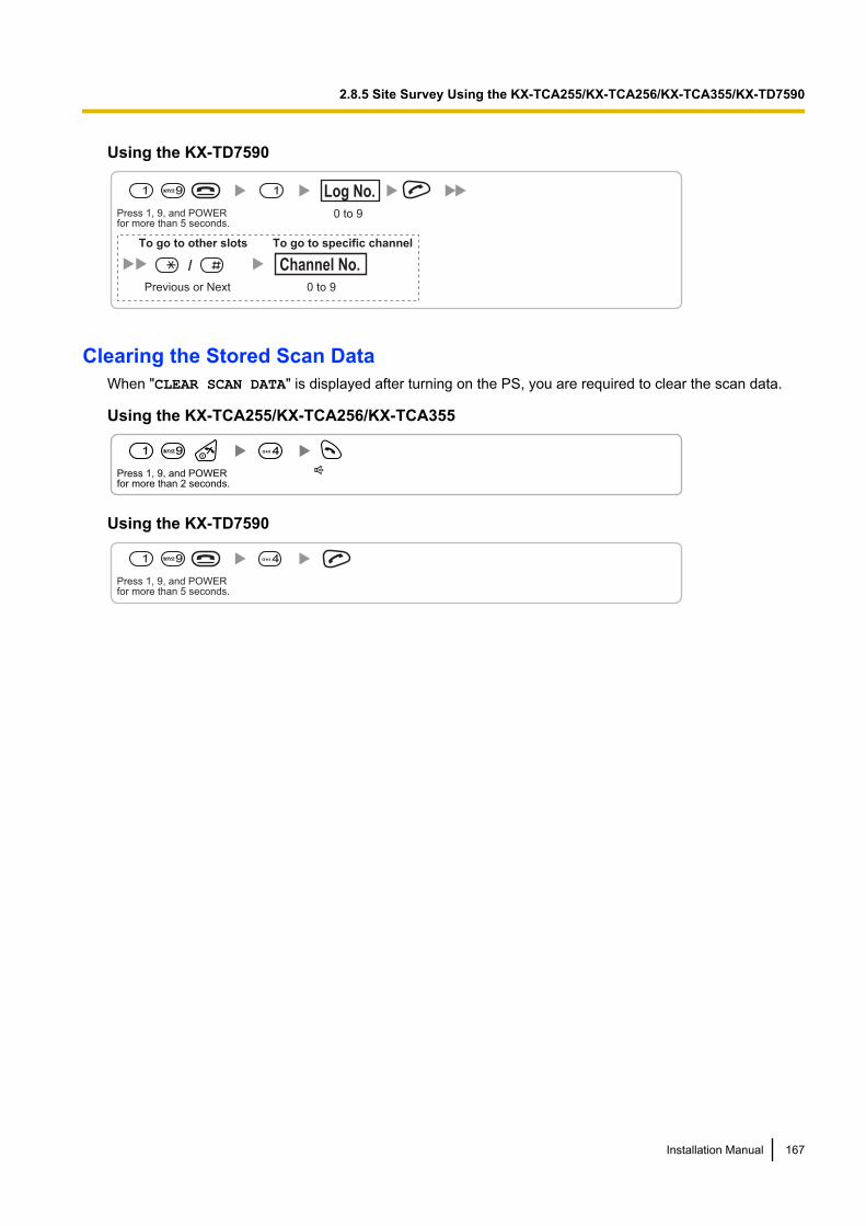
Using the KX-TD7590
Press 1, 9, and POWERfor more than 5 seconds.
0 to 9
Log No.1 99 1
Previous or Next 0 to 9
Channel No.
To go to other slots To go to specific channel
/
Clearing the Stored Scan DataWhen "CLEAR SCAN DATA" is displayed after turning on the PS, you are required to clear the scan data.
Using the KX-TCA255/KX-TCA256/KX-TCA355
Press 1, 9, and POWERfor more than 2 seconds.
1 99 4GHI
Using the KX-TD7590
Press 1, 9, and POWERfor more than 5 seconds.
1 99 4GHI
Installation Manual 167
2.8.5 Site Survey Using the KX-TCA255/KX-TCA256/KX-TCA355/KX-TD7590
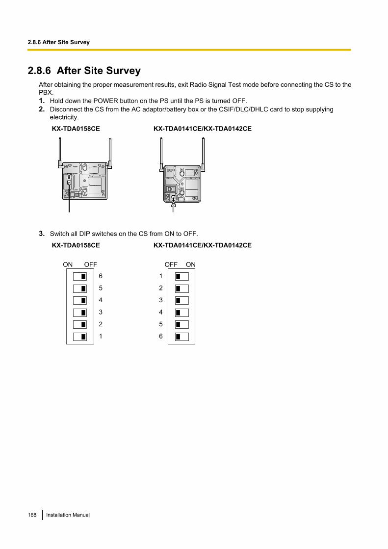
2.8.6 After Site SurveyAfter obtaining the proper measurement results, exit Radio Signal Test mode before connecting the CS to thePBX.1. Hold down the POWER button on the PS until the PS is turned OFF.2. Disconnect the CS from the AC adaptor/battery box or the CSIF/DLC/DHLC card to stop supplying
electricity.
KX-TDA0158CE KX-TDA0141CE/KX-TDA0142CE
3. Switch all DIP switches on the CS from ON to OFF.
KX-TDA0158CE
6
5
4
3
2
1
ON OFF
KX-TDA0141CE/KX-TDA0142CE
1
2
3
4
5
6
OFF ON
168 Installation Manual
2.8.6 After Site Survey
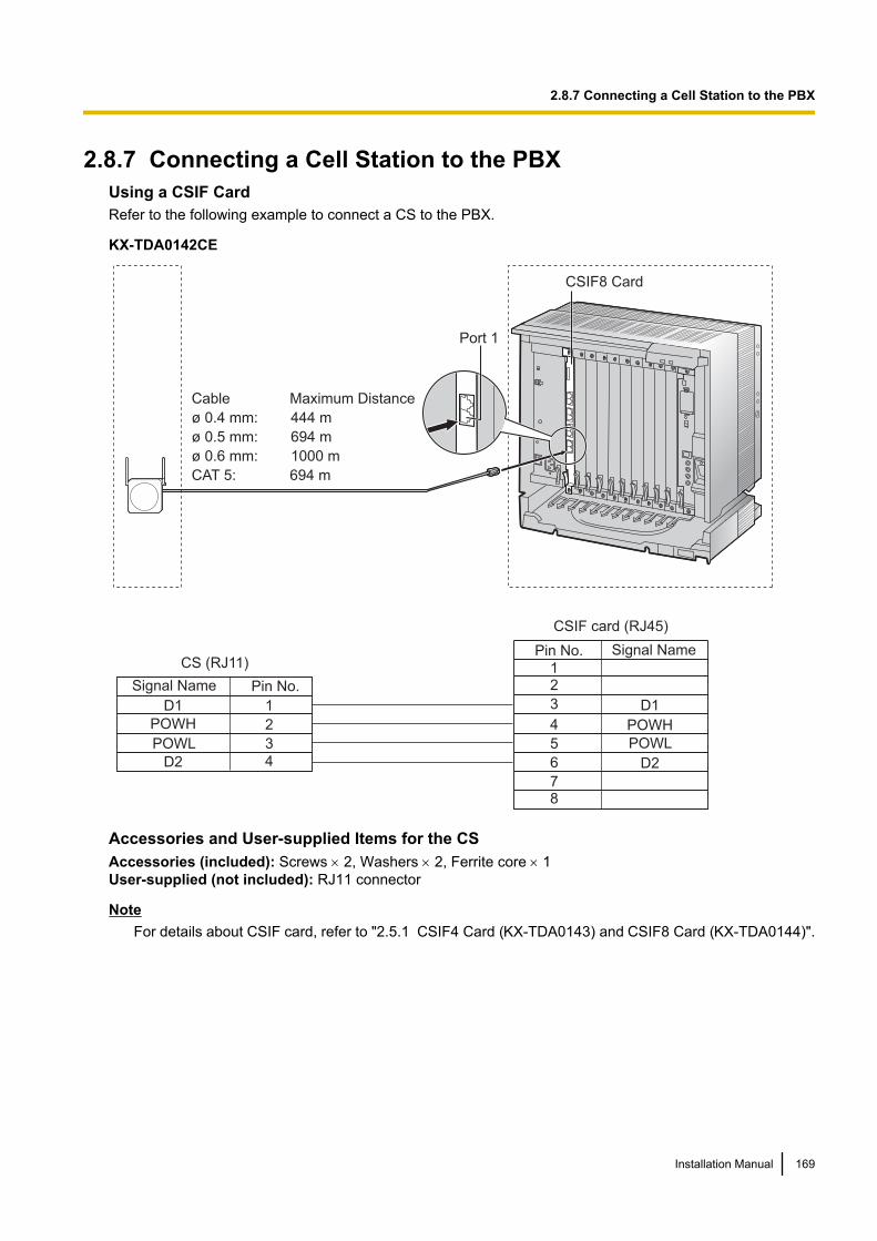
2.8.7 Connecting a Cell Station to the PBXUsing a CSIF CardRefer to the following example to connect a CS to the PBX.
KX-TDA0142CE
Signal Name
Signal Name Pin No.
1
2
3
4
D1
POWH
POWL
D2
D1
POWH
POWL
D2
Pin No.
12
3
4
5
6
78
CSIF card (RJ45)
CS (RJ11)
Cable Maximum Distance
ø 0.4 mm: 444 m
ø 0.5 mm: 694 m
ø 0.6 mm: 1000 m
CAT 5: 694 m
Port 1
CSIF8 Card
Accessories and User-supplied Items for the CSAccessories (included): Screws ´ 2, Washers ´ 2, Ferrite core ´ 1User-supplied (not included): RJ11 connector
NoteFor details about CSIF card, refer to "2.5.1 CSIF4 Card (KX-TDA0143) and CSIF8 Card (KX-TDA0144)".
Installation Manual 169
2.8.7 Connecting a Cell Station to the PBX
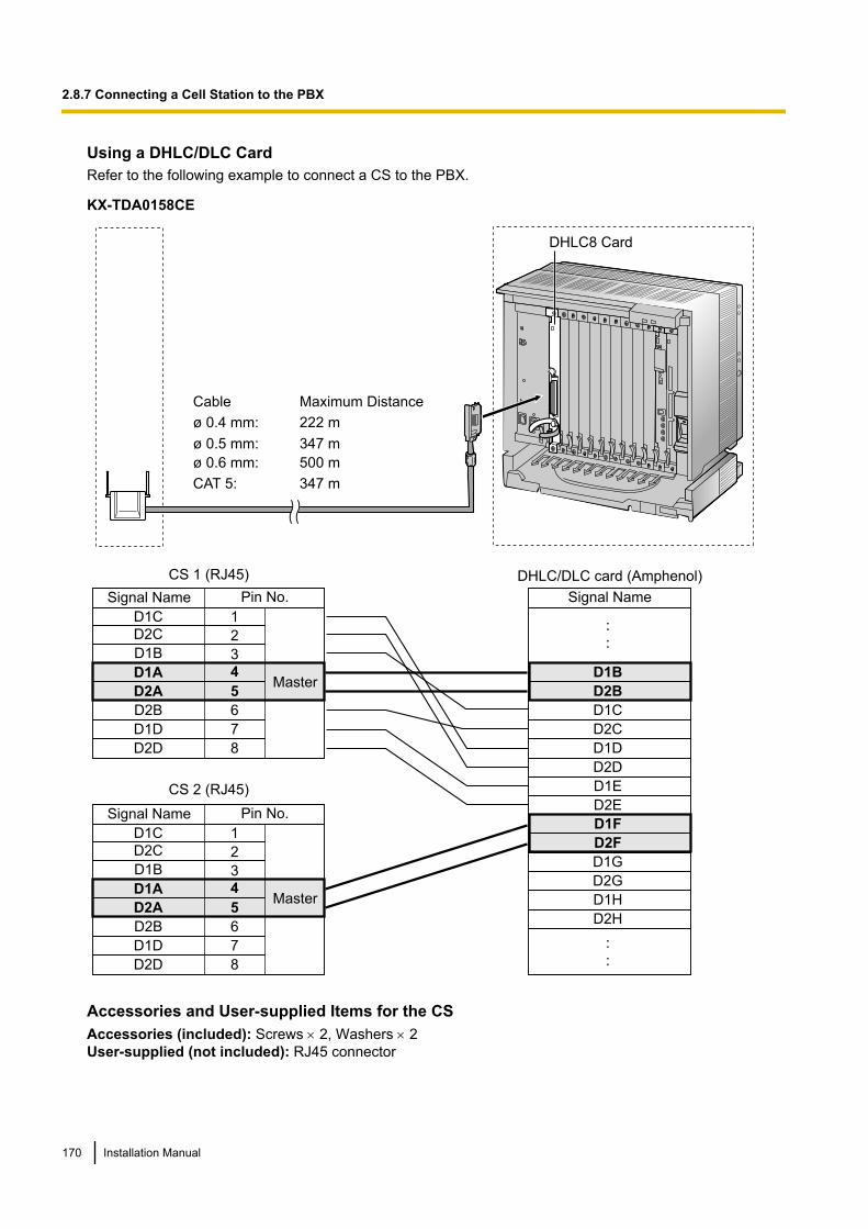
Using a DHLC/DLC CardRefer to the following example to connect a CS to the PBX.
KX-TDA0158CE
D1B
D2B
D1C
D2C
D1D
D2D
D1E
D2E
D1F
D2F
D1G
D2G
D1H
D2H
1
2
3
4
5
6
7
8
D1C
D2C
D1B
D2A
D2B
D1D
D2D
D1A
1
2
3
4
5
6
7
8
D1C
D2C
D1B
D2A
D2B
D1D
D2D
D1A
DHLC8 Card
CS 1 (RJ45)
CS 2 (RJ45)
Signal Name
DHLC/DLC card (Amphenol)
Cable Maximum Distance
ø 0.4 mm: 222 m
ø 0.5 mm: 347 m
ø 0.6 mm: 500 m
CAT 5: 347 m
Pin No.Signal Name
Master
Pin No.Signal Name
Master
Accessories and User-supplied Items for the CSAccessories (included): Screws ´ 2, Washers ´ 2User-supplied (not included): RJ45 connector
170 Installation Manual
2.8.7 Connecting a Cell Station to the PBX
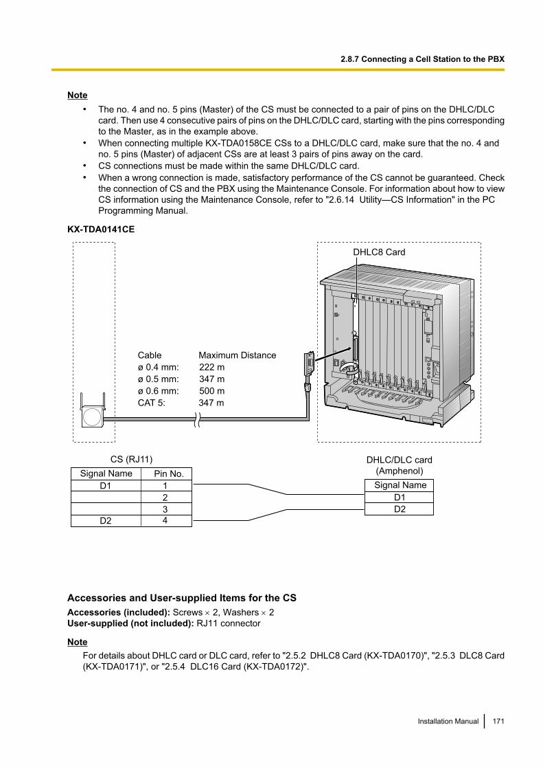
Note• The no. 4 and no. 5 pins (Master) of the CS must be connected to a pair of pins on the DHLC/DLC
card. Then use 4 consecutive pairs of pins on the DHLC/DLC card, starting with the pins correspondingto the Master, as in the example above.
• When connecting multiple KX-TDA0158CE CSs to a DHLC/DLC card, make sure that the no. 4 andno. 5 pins (Master) of adjacent CSs are at least 3 pairs of pins away on the card.
• CS connections must be made within the same DHLC/DLC card.• When a wrong connection is made, satisfactory performance of the CS cannot be guaranteed. Check
the connection of CS and the PBX using the Maintenance Console. For information about how to viewCS information using the Maintenance Console, refer to "2.6.14 Utility—CS Information" in the PCProgramming Manual.
KX-TDA0141CE
Signal Name
D1
D2
DHLC/DLC card
(Amphenol)
Cable Maximum Distance
ø 0.4 mm: 222 m
ø 0.5 mm: 347 m
ø 0.6 mm: 500 m
CAT 5: 347 m
Signal Name Pin No.
1
2
3
4
D1
D2
CS (RJ11)
DHLC8 Card
Accessories and User-supplied Items for the CSAccessories (included): Screws ´ 2, Washers ´ 2User-supplied (not included): RJ11 connector
NoteFor details about DHLC card or DLC card, refer to "2.5.2 DHLC8 Card (KX-TDA0170)", "2.5.3 DLC8 Card(KX-TDA0171)", or "2.5.4 DLC16 Card (KX-TDA0172)".
Installation Manual 171
2.8.7 Connecting a Cell Station to the PBX
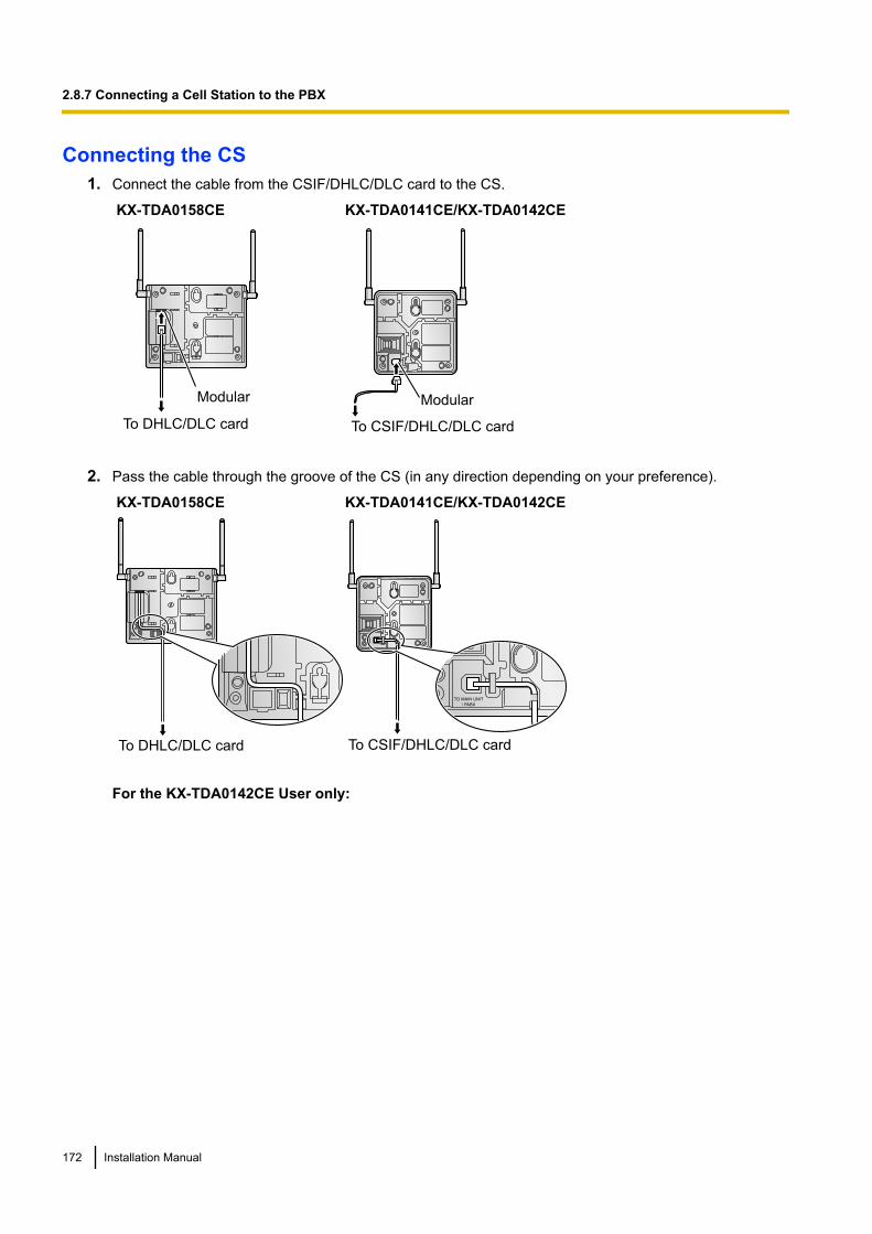
Connecting the CS1. Connect the cable from the CSIF/DHLC/DLC card to the CS.
KX-TDA0158CE
Modular
To DHLC/DLC card
KX-TDA0141CE/KX-TDA0142CE
Modular
To CSIF/DHLC/DLC card
2. Pass the cable through the groove of the CS (in any direction depending on your preference).
KX-TDA0158CE
To DHLC/DLC card
KX-TDA0141CE/KX-TDA0142CE
To CSIF/DHLC/DLC card
For the KX-TDA0142CE User only:
172 Installation Manual
2.8.7 Connecting a Cell Station to the PBX
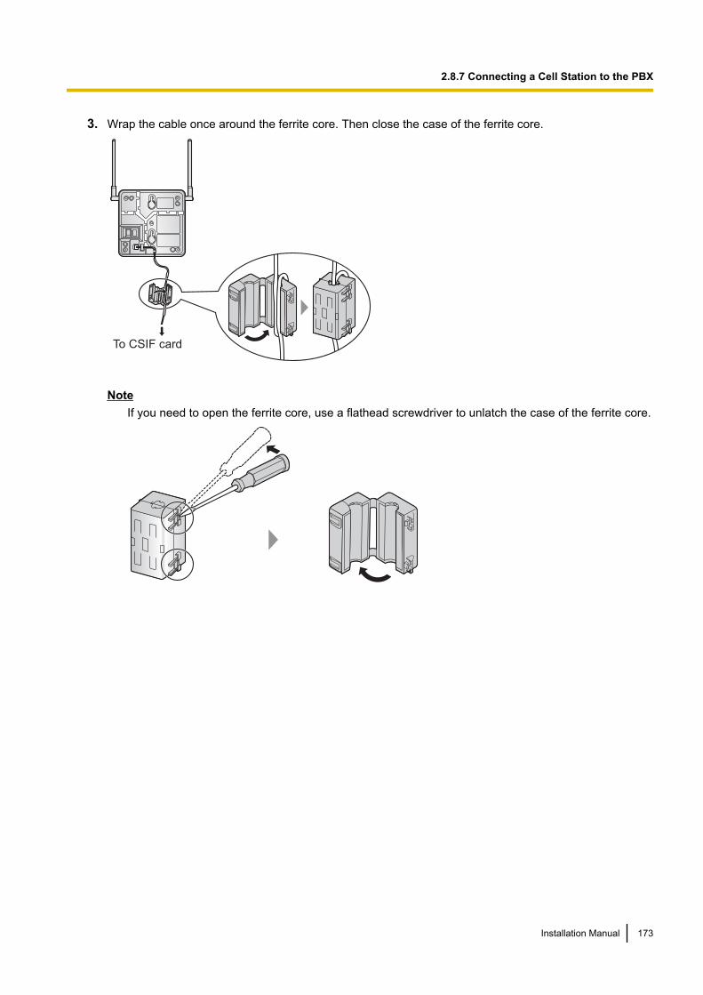
3. Wrap the cable once around the ferrite core. Then close the case of the ferrite core.
To CSIF card
NoteIf you need to open the ferrite core, use a flathead screwdriver to unlatch the case of the ferrite core.
Installation Manual 173
2.8.7 Connecting a Cell Station to the PBX
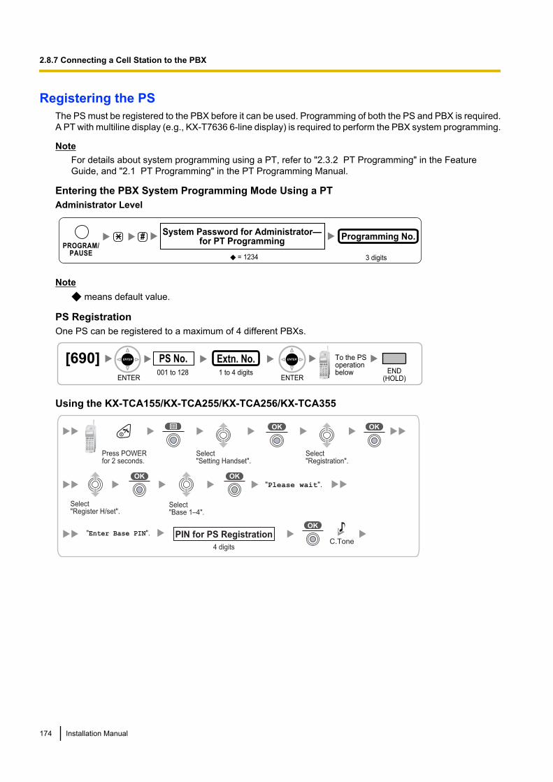
Registering the PSThe PS must be registered to the PBX before it can be used. Programming of both the PS and PBX is required.A PT with multiline display (e.g., KX-T7636 6-line display) is required to perform the PBX system programming.
NoteFor details about system programming using a PT, refer to "2.3.2 PT Programming" in the FeatureGuide, and "2.1 PT Programming" in the PT Programming Manual.
Entering the PBX System Programming Mode Using a PTAdministrator Level
#
= 1234
System Password for Administrator—for PT Programming
Programming No.
3 digits
PROGRAM/PAUSE
Note means default value.
PS RegistrationOne PS can be registered to a maximum of 4 different PBXs.
[690]001 to 128
PS No.1 to 4 digits END
(HOLD)ENTER ENTER
To the PSoperationbelow
Extn. No.
Using the KX-TCA155/KX-TCA255/KX-TCA256/KX-TCA355
Select "Setting Handset".
Select "Register H/set".
Select "Registration".
Select "Base 1–4".
"Please wait".
"Enter Base PIN".
Press POWERfor 2 seconds.
C.Tone4 digits
PIN for PS Registration
174 Installation Manual
2.8.7 Connecting a Cell Station to the PBX
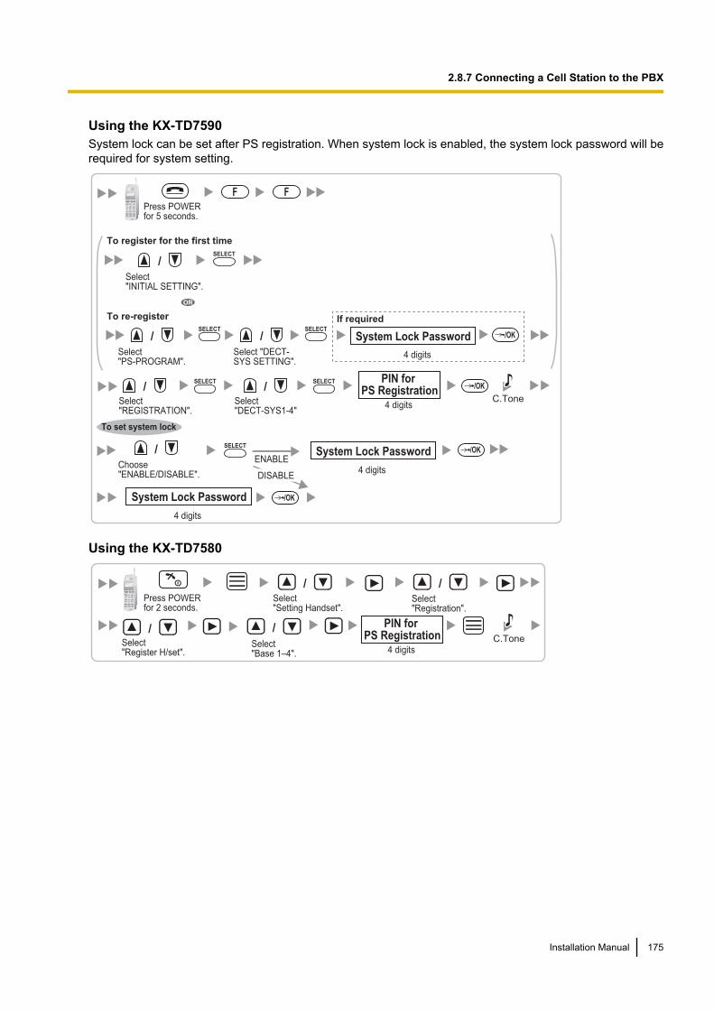
Using the KX-TD7590System lock can be set after PS registration. When system lock is enabled, the system lock password will berequired for system setting.
Select "DECT-SYS1-4"
4 digits
Choose "ENABLE/DISABLE".
PIN for PS Registration
System Lock Password
System Lock Password
Press POWER for 5 seconds.
4 digits
4 digits
ENABLE
F
/
/
SELECT
SELECT
SELECT/OK
/OK
/OK
C.Tone
To set system lock
F
DISABLE
OR
To register for the first time
To re-register
/
Select "INITIAL SETTING".
SELECT
/
Select "PS-PROGRAM".
SELECT
/
Select "DECT-SYS SETTING".
SELECT
4 digits
If required
/OK System Lock Password
Select "REGISTRATION".
/
Using the KX-TD7580
/Select "Setting Handset".
Select "Register H/set".
Select "Registration".
Select "Base 1–4".
Press POWERfor 2 seconds.
/
/ /C.Tone
4 digits
PIN for PS Registration
Installation Manual 175
2.8.7 Connecting a Cell Station to the PBX
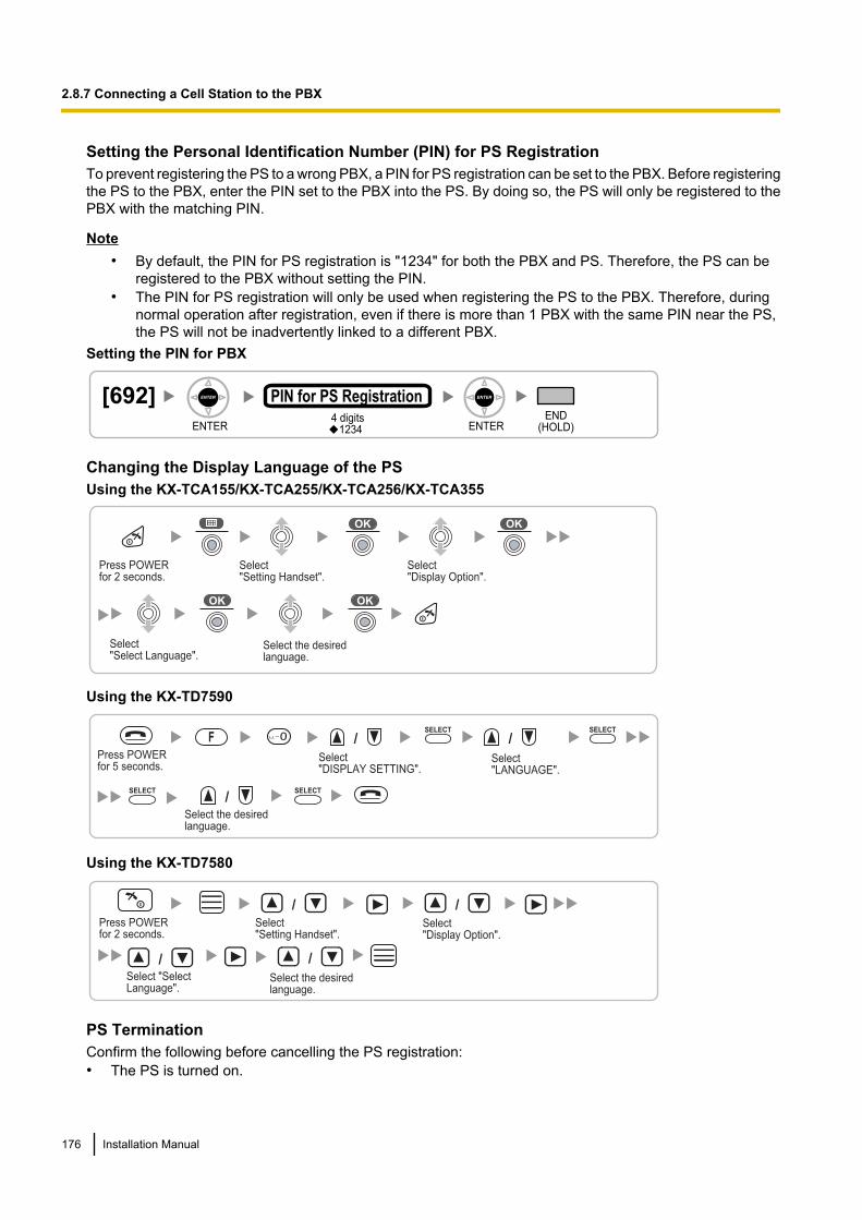
Setting the Personal Identification Number (PIN) for PS RegistrationTo prevent registering the PS to a wrong PBX, a PIN for PS registration can be set to the PBX. Before registeringthe PS to the PBX, enter the PIN set to the PBX into the PS. By doing so, the PS will only be registered to thePBX with the matching PIN.
Note• By default, the PIN for PS registration is "1234" for both the PBX and PS. Therefore, the PS can be
registered to the PBX without setting the PIN.• The PIN for PS registration will only be used when registering the PS to the PBX. Therefore, during
normal operation after registration, even if there is more than 1 PBX with the same PIN near the PS,the PS will not be inadvertently linked to a different PBX.
Setting the PIN for PBX
[692]4 digits
PIN for PS RegistrationEND
(HOLD)ENTER ENTER1234
Changing the Display Language of the PSUsing the KX-TCA155/KX-TCA255/KX-TCA256/KX-TCA355
Select "Setting Handset".
Select "Select Language".
Select "Display Option".
Select the desired language.
Press POWERfor 2 seconds.
Using the KX-TD7590
/
Select "DISPLAY SETTING".
Select the desiredlanguage.
Select "LANGUAGE".
Press POWER for 5 seconds.
F
/
/SELECT
SELECTSELECT
0SELECT
Using the KX-TD7580
/Select "Setting Handset".
Select "Select Language".
Select "Display Option".
Select the desired language.
Press POWERfor 2 seconds.
/
/ /
PS TerminationConfirm the following before cancelling the PS registration:• The PS is turned on.
176 Installation Manual
2.8.7 Connecting a Cell Station to the PBX
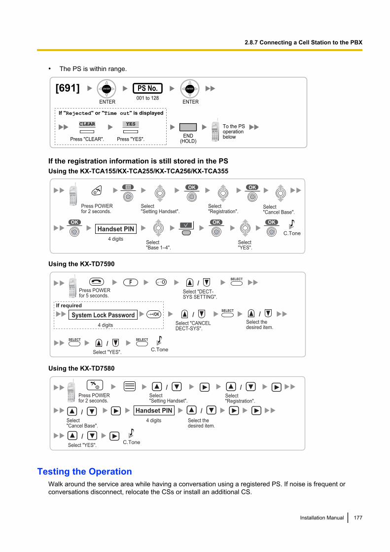
• The PS is within range.
[691]001 to 128
PS No.
ENTER ENTER
END(HOLD)
To the PSoperationbelow
If "Rejected" or "Time out" is displayed
CLEAR YES
Press "YES".Press "CLEAR".
If the registration information is still stored in the PSUsing the KX-TCA155/KX-TCA255/KX-TCA256/KX-TCA355
4 digits
Handset PIN
Select "Setting Handset".
Select "Registration".
Select "Base 1–4".
Press POWERfor 2 seconds.
C.Tone
Select "YES".
Select "Cancel Base".
Using the KX-TD7590
Select thedesired item.
F
/
0 /
Select "DECT-SYS SETTING".
SELECT
4 digits
If required
/OK System Lock Password /
Select "CANCELDECT-SYS".
SELECT
SELECT
/
Select "YES".C.Tone
Press POWER for 5 seconds.
SELECT
Using the KX-TD7580
/Select "Setting Handset".
Select "Cancel Base".
Select "Registration".
Press POWERfor 2 seconds.
/
/
C.Tone
4 digits
Handset PIN
Select thedesired item.
/
Select "YES".
/
Testing the OperationWalk around the service area while having a conversation using a registered PS. If noise is frequent orconversations disconnect, relocate the CSs or install an additional CS.
Installation Manual 177
2.8.7 Connecting a Cell Station to the PBX
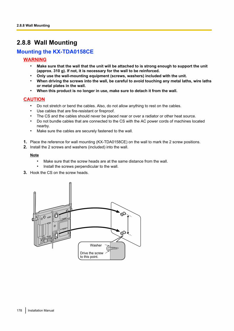
2.8.8 Wall MountingMounting the KX-TDA0158CE
WARNING• Make sure that the wall that the unit will be attached to is strong enough to support the unit
(approx. 310 g). If not, it is necessary for the wall to be reinforced.• Only use the wall-mounting equipment (screws, washers) included with the unit.• When driving the screws into the wall, be careful to avoid touching any metal laths, wire laths
or metal plates in the wall.• When this product is no longer in use, make sure to detach it from the wall.
CAUTION• Do not stretch or bend the cables. Also, do not allow anything to rest on the cables.• Use cables that are fire-resistant or fireproof.• The CS and the cables should never be placed near or over a radiator or other heat source.• Do not bundle cables that are connected to the CS with the AC power cords of machines located
nearby.• Make sure the cables are securely fastened to the wall.
1. Place the reference for wall mounting (KX-TDA0158CE) on the wall to mark the 2 screw positions.2. Install the 2 screws and washers (included) into the wall.
Note• Make sure that the screw heads are at the same distance from the wall.• Install the screws perpendicular to the wall.
3. Hook the CS on the screw heads.
Washer
Drive the screw to this point.
178 Installation Manual
2.8.8 Wall Mounting
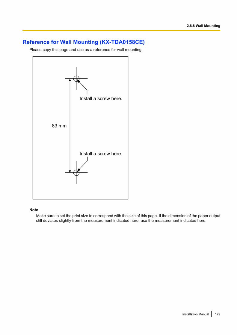
Reference for Wall Mounting (KX-TDA0158CE)Please copy this page and use as a reference for wall mounting.
Install a screw here.
Install a screw here.
83 mm
NoteMake sure to set the print size to correspond with the size of this page. If the dimension of the paper outputstill deviates slightly from the measurement indicated here, use the measurement indicated here.
Installation Manual 179
2.8.8 Wall Mounting
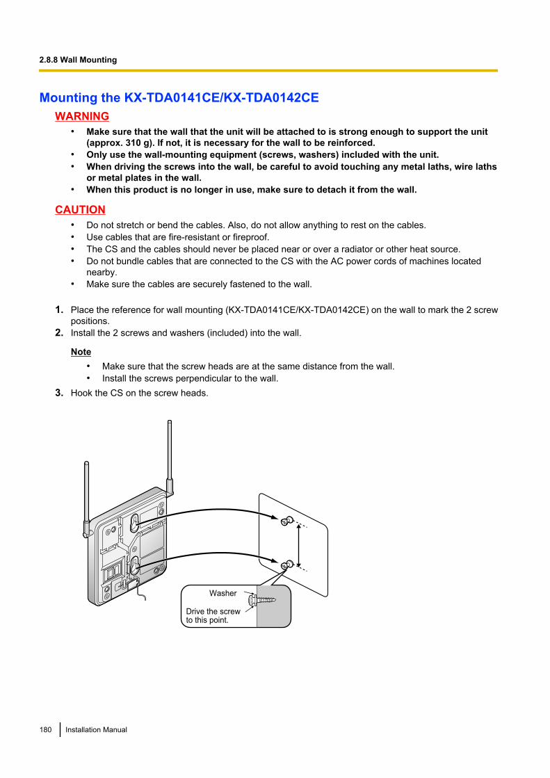
Mounting the KX-TDA0141CE/KX-TDA0142CEWARNING
• Make sure that the wall that the unit will be attached to is strong enough to support the unit(approx. 310 g). If not, it is necessary for the wall to be reinforced.
• Only use the wall-mounting equipment (screws, washers) included with the unit.• When driving the screws into the wall, be careful to avoid touching any metal laths, wire laths
or metal plates in the wall.• When this product is no longer in use, make sure to detach it from the wall.
CAUTION• Do not stretch or bend the cables. Also, do not allow anything to rest on the cables.• Use cables that are fire-resistant or fireproof.• The CS and the cables should never be placed near or over a radiator or other heat source.• Do not bundle cables that are connected to the CS with the AC power cords of machines located
nearby.• Make sure the cables are securely fastened to the wall.
1. Place the reference for wall mounting (KX-TDA0141CE/KX-TDA0142CE) on the wall to mark the 2 screwpositions.
2. Install the 2 screws and washers (included) into the wall.
Note• Make sure that the screw heads are at the same distance from the wall.• Install the screws perpendicular to the wall.
3. Hook the CS on the screw heads.
Washer
Drive the screw to this point.
180 Installation Manual
2.8.8 Wall Mounting
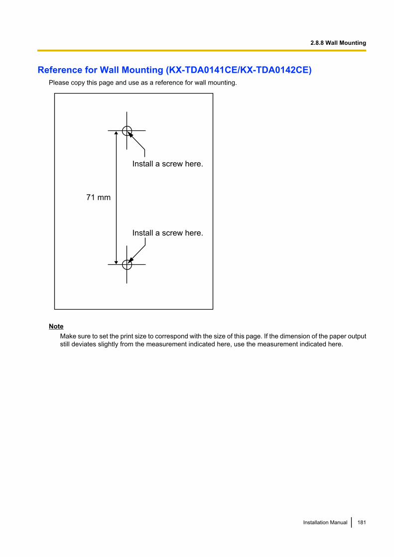
Reference for Wall Mounting (KX-TDA0141CE/KX-TDA0142CE)Please copy this page and use as a reference for wall mounting.
Install a screw here.
Install a screw here.
71 mm
NoteMake sure to set the print size to correspond with the size of this page. If the dimension of the paper outputstill deviates slightly from the measurement indicated here, use the measurement indicated here.
Installation Manual 181
2.8.8 Wall Mounting
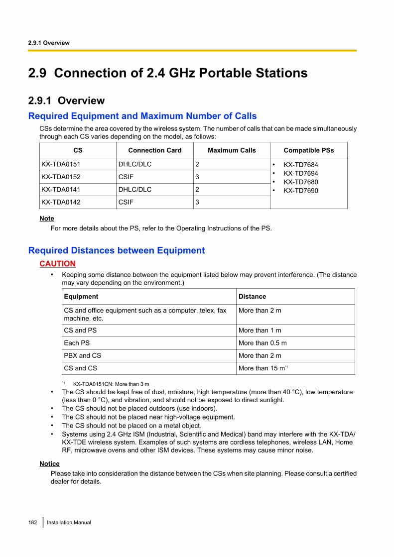
2.9 Connection of 2.4 GHz Portable Stations
2.9.1 OverviewRequired Equipment and Maximum Number of Calls
CSs determine the area covered by the wireless system. The number of calls that can be made simultaneouslythrough each CS varies depending on the model, as follows:
CS Connection Card Maximum Calls Compatible PSs
KX-TDA0151 DHLC/DLC 2 • KX-TD7684• KX-TD7694• KX-TD7680• KX-TD7690
KX-TDA0152 CSIF 3
KX-TDA0141 DHLC/DLC 2
KX-TDA0142 CSIF 3
NoteFor more details about the PS, refer to the Operating Instructions of the PS.
Required Distances between EquipmentCAUTION
• Keeping some distance between the equipment listed below may prevent interference. (The distancemay vary depending on the environment.)
Equipment Distance
CS and office equipment such as a computer, telex, faxmachine, etc.
More than 2 m
CS and PS More than 1 m
Each PS More than 0.5 m
PBX and CS More than 2 m
CS and CS More than 15 m*1
*1 KX-TDA0151CN: More than 3 m• The CS should be kept free of dust, moisture, high temperature (more than 40 °C), low temperature
(less than 0 °C), and vibration, and should not be exposed to direct sunlight.• The CS should not be placed outdoors (use indoors).• The CS should not be placed near high-voltage equipment.• The CS should not be placed on a metal object.• Systems using 2.4 GHz ISM (Industrial, Scientific and Medical) band may interfere with the KX-TDA/
KX-TDE wireless system. Examples of such systems are cordless telephones, wireless LAN, HomeRF, microwave ovens and other ISM devices. These systems may cause minor noise.
NoticePlease take into consideration the distance between the CSs when site planning. Please consult a certifieddealer for details.
182 Installation Manual
2.9.1 Overview
However, the required distance between CSs may vary depending on the environment of the installationsite and conditions in which the wireless system is used. Conduct the site survey to determine theappropriate distance.
Installation Manual 183
2.9.1 Overview
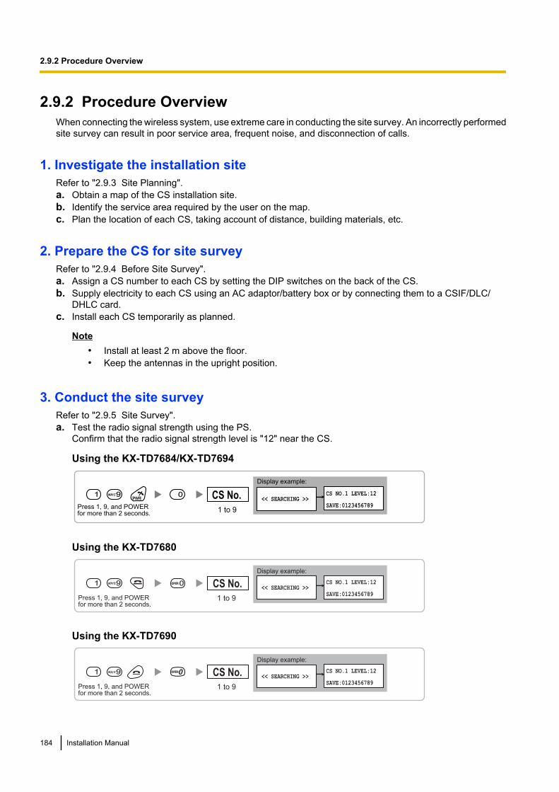
2.9.2 Procedure OverviewWhen connecting the wireless system, use extreme care in conducting the site survey. An incorrectly performedsite survey can result in poor service area, frequent noise, and disconnection of calls.
1. Investigate the installation siteRefer to "2.9.3 Site Planning".a. Obtain a map of the CS installation site.b. Identify the service area required by the user on the map.c. Plan the location of each CS, taking account of distance, building materials, etc.
2. Prepare the CS for site surveyRefer to "2.9.4 Before Site Survey".a. Assign a CS number to each CS by setting the DIP switches on the back of the CS.b. Supply electricity to each CS using an AC adaptor/battery box or by connecting them to a CSIF/DLC/
DHLC card.c. Install each CS temporarily as planned.
Note• Install at least 2 m above the floor.• Keep the antennas in the upright position.
3. Conduct the site surveyRefer to "2.9.5 Site Survey".a. Test the radio signal strength using the PS.
Confirm that the radio signal strength level is "12" near the CS.
Using the KX-TD7684/KX-TD7694
0 << SEARCHING >>
CS NO.1 LEVEL:12
SAVE:0123456789
1 9
Press 1, 9, and POWER for more than 2 seconds.
Display example:
1 to 9
CS No.
Using the KX-TD7680
Display example:
Press 1, 9, and POWERfor more than 2 seconds.
<< SEARCHING >>CS NO.1 LEVEL:12
SAVE:01234567891 to 9
CS No.1 9 0
Using the KX-TD7690
Display example:
Press 1, 9, and POWERfor more than 2 seconds.
<< SEARCHING >>CS NO.1 LEVEL:12
SAVE:01234567891 to 9
CS No.1 99
184 Installation Manual
2.9.2 Procedure Overview
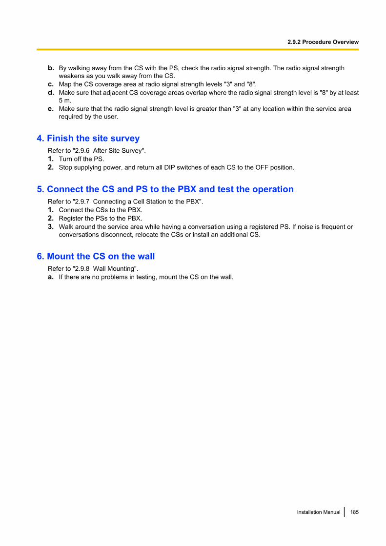
b. By walking away from the CS with the PS, check the radio signal strength. The radio signal strengthweakens as you walk away from the CS.
c. Map the CS coverage area at radio signal strength levels "3" and "8".d. Make sure that adjacent CS coverage areas overlap where the radio signal strength level is "8" by at least
5 m.e. Make sure that the radio signal strength level is greater than "3" at any location within the service area
required by the user.
4. Finish the site surveyRefer to "2.9.6 After Site Survey".1. Turn off the PS.2. Stop supplying power, and return all DIP switches of each CS to the OFF position.
5. Connect the CS and PS to the PBX and test the operationRefer to "2.9.7 Connecting a Cell Station to the PBX".1. Connect the CSs to the PBX.2. Register the PSs to the PBX.3. Walk around the service area while having a conversation using a registered PS. If noise is frequent or
conversations disconnect, relocate the CSs or install an additional CS.
6. Mount the CS on the wallRefer to "2.9.8 Wall Mounting".a. If there are no problems in testing, mount the CS on the wall.
Installation Manual 185
2.9.2 Procedure Overview

2.9.3 Site PlanningChoosing the best site for the CS requires careful planning and testing of essential areas. The best locationmay not always be convenient for installation. Read the following information before installing the unit.
Understanding Radio WavesCharacteristics of Radio WavesThe transmission of radio waves and the CS coverage area depend on the structure and materials of thebuilding.Office equipment, such as computers and fax machines, can interfere with radio waves. Such equipment maycreate noise or interfere with the performance of the PS.The illustration below shows the special transmitting patterns of radio waves.1. Radio waves are reflected by objects made of materials such as metal.2. Radio waves are diffracted by objects such as metallic columns.3. Radio waves penetrate objects made of materials such as glass.
CS
Column
3. Penetration
2. Diffraction
1. Reflection
Relationships Between Radio Waves and Building Structure and Materials• The CS coverage area is affected more by the building materials and their thickness than the number of
obstacles.• Radio waves tend to be reflected or diffracted by conductive objects and rarely penetrate them.• Radio waves tend to penetrate insulated objects and are rarely reflected by them.• Radio waves penetrate thin objects more than thick objects.• The table below shows the transmission tendency of radio waves when they reach objects made from
various materials.
Object Material Transmission Tendency
Wall Concrete The thicker they are, the less radio waves penetrate them.
Ferroconcrete Radio waves can penetrate them, but the more iron thereis, the more radio waves are reflected.
186 Installation Manual
2.9.3 Site Planning
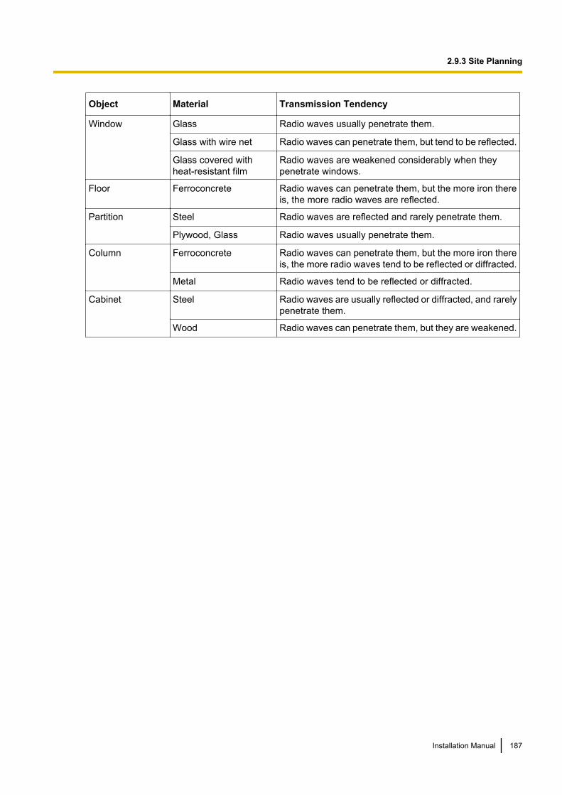
Object Material Transmission Tendency
Window Glass Radio waves usually penetrate them.
Glass with wire net Radio waves can penetrate them, but tend to be reflected.
Glass covered withheat-resistant film
Radio waves are weakened considerably when theypenetrate windows.
Floor Ferroconcrete Radio waves can penetrate them, but the more iron thereis, the more radio waves are reflected.
Partition Steel Radio waves are reflected and rarely penetrate them.
Plywood, Glass Radio waves usually penetrate them.
Column Ferroconcrete Radio waves can penetrate them, but the more iron thereis, the more radio waves tend to be reflected or diffracted.
Metal Radio waves tend to be reflected or diffracted.
Cabinet Steel Radio waves are usually reflected or diffracted, and rarelypenetrate them.
Wood Radio waves can penetrate them, but they are weakened.
Installation Manual 187
2.9.3 Site Planning
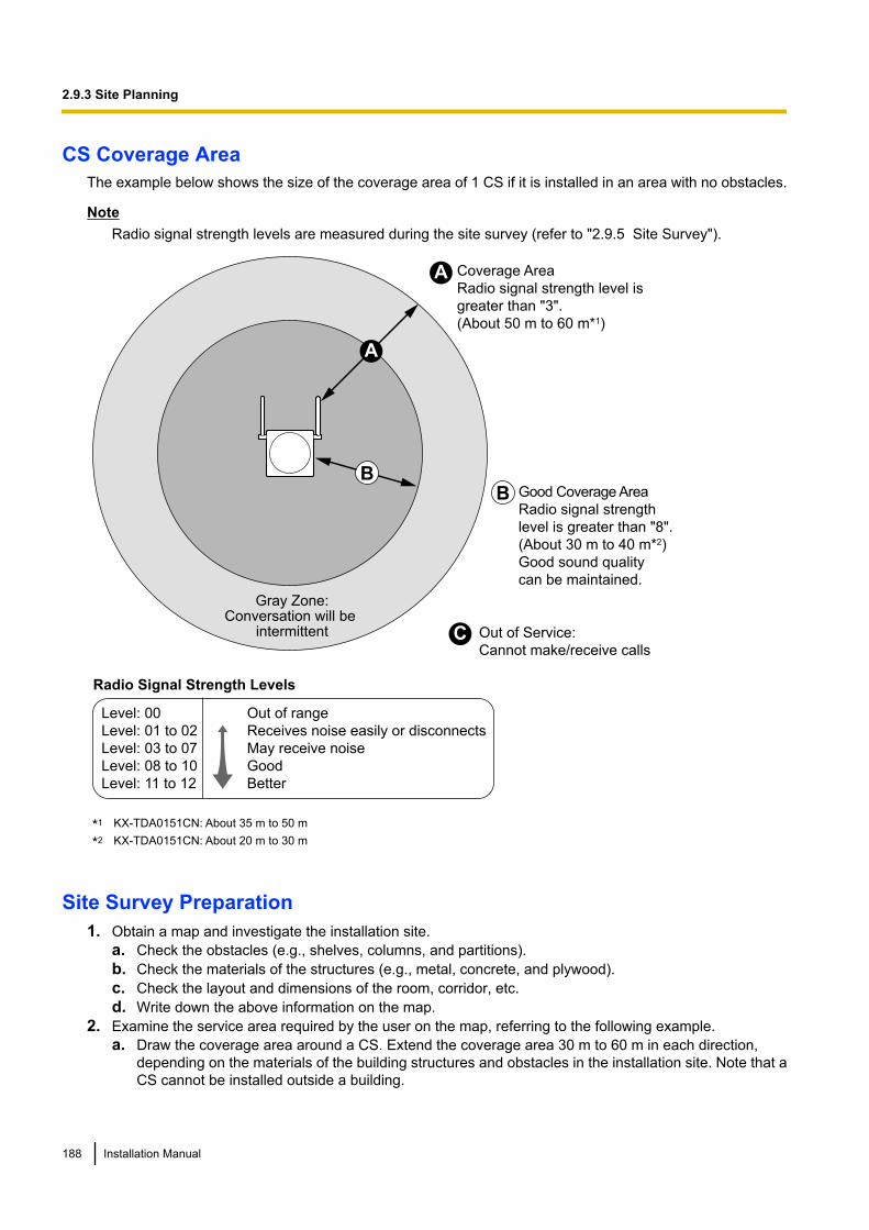
CS Coverage AreaThe example below shows the size of the coverage area of 1 CS if it is installed in an area with no obstacles.
NoteRadio signal strength levels are measured during the site survey (refer to "2.9.5 Site Survey").
Gray Zone:Conversation will be
intermittent
Coverage Area
Radio signal strength level is
greater than "3".
(About 50 m to 60 m*1)
Good Coverage Area
Radio signal strength
level is greater than "8".
(About 30 m to 40 m*2)
Good sound quality
can be maintained.
Out of Service:
Cannot make/receive calls
A
B
A
B
Radio Signal Strength Levels
C
Out of range
Receives noise easily or disconnects
May receive noise
Good
Better
Level: 00
Level: 01 to 02
Level: 03 to 07
Level: 08 to 10
Level: 11 to 12
KX-TDA0151CN: About 35 m to 50 m*1
KX-TDA0151CN: About 20 m to 30 m*2
Site Survey Preparation1. Obtain a map and investigate the installation site.
a. Check the obstacles (e.g., shelves, columns, and partitions).b. Check the materials of the structures (e.g., metal, concrete, and plywood).c. Check the layout and dimensions of the room, corridor, etc.d. Write down the above information on the map.
2. Examine the service area required by the user on the map, referring to the following example.a. Draw the coverage area around a CS. Extend the coverage area 30 m to 60 m in each direction,
depending on the materials of the building structures and obstacles in the installation site. Note that aCS cannot be installed outside a building.
188 Installation Manual
2.9.3 Site Planning
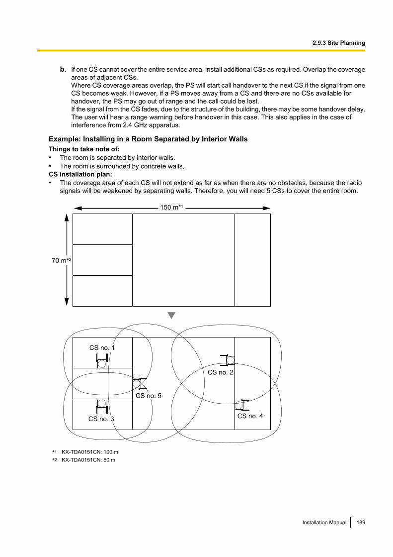
b. If one CS cannot cover the entire service area, install additional CSs as required. Overlap the coverageareas of adjacent CSs.Where CS coverage areas overlap, the PS will start call handover to the next CS if the signal from oneCS becomes weak. However, if a PS moves away from a CS and there are no CSs available forhandover, the PS may go out of range and the call could be lost.If the signal from the CS fades, due to the structure of the building, there may be some handover delay.The user will hear a range warning before handover in this case. This also applies in the case ofinterference from 2.4 GHz apparatus.
Example: Installing in a Room Separated by Interior WallsThings to take note of:• The room is separated by interior walls.• The room is surrounded by concrete walls.CS installation plan:• The coverage area of each CS will not extend as far as when there are no obstacles, because the radio
signals will be weakened by separating walls. Therefore, you will need 5 CSs to cover the entire room.
70 m*2
CS no. 5
CS no. 1
CS no. 2
CS no. 4CS no. 3
150 m*1
KX-TDA0151CN: 100 m*1
KX-TDA0151CN: 50 m*2
Installation Manual 189
2.9.3 Site Planning
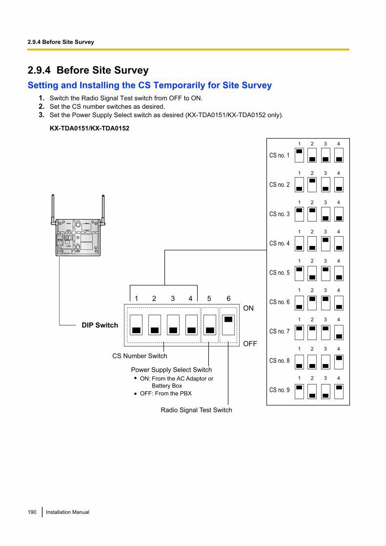
2.9.4 Before Site SurveySetting and Installing the CS Temporarily for Site Survey
1. Switch the Radio Signal Test switch from OFF to ON.2. Set the CS number switches as desired.3. Set the Power Supply Select switch as desired (KX-TDA0151/KX-TDA0152 only).
KX-TDA0151/KX-TDA0152
1 2 3 4 5 6
4
4
4
4
4
4
4
4
4
3
3
3
3
3
3
3
3
3
2
2
2
2
2
2
2
2
2
1
1
1
1
1
1
1
1
1
CS no. 1
CS no. 2
CS no. 3
CS no. 4
CS no. 5
CS no. 6
CS no. 7
CS no. 8
CS no. 9
DIP Switch
Radio Signal Test Switch
Power Supply Select Switch
CS Number Switch
ON:
OFF: From the PBX
OFF
ON
From the AC Adaptor or
Battery Box
190 Installation Manual
2.9.4 Before Site Survey

KX-TDA0141/KX-TDA0142
CS Number Switch
CS no. 1 CS no. 2 CS no. 3 CS no. 4 CS no. 5 CS no. 6 CS no. 7 CS no. 8 CS no. 9
1
2
3
4
1
2
3
4
1
2
3
4
1
2
3
4
1
2
3
4
1
2
3
4
1
2
3
4
1
2
3
4
1
2
3
4
DIP Switch
1
2
3
4
5
6
OFF ON
Radio Signal
Test Switch
Keep this switch at the default
"OFF" position. Otherwise, the
CS will not function.
NoteIf more than 1 CS is in Radio Signal Test mode, each CS must have a unique CS number.
4. After setting the DIP switches, connect the CS to an AC adaptor/battery box using a power supply adaptor.
WARNINGThe AC adaptor should be connected to a vertically oriented or floor-mounted AC outlet. Do notconnect the AC adaptor to a ceiling-mounted AC outlet, as the weight of the adaptor may causeit to become disconnected.
NoticeIf the Power Supply Select switch is set to ON in step 3, connect the CS to an AC adaptor/battery box.If it is set to OFF, connect the CS to a CSIF/DLC/DHLC card (KX-TDA0151/KX-TDA0152 only).
Installation Manual 191
2.9.4 Before Site Survey
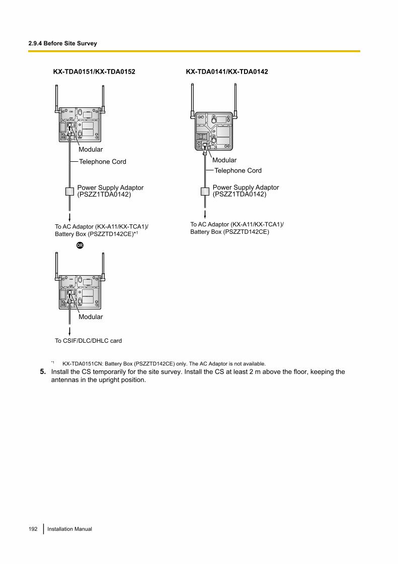
KX-TDA0151/KX-TDA0152 KX-TDA0141/KX-TDA0142
To AC Adaptor (KX-A11/KX-TCA1)/
Battery Box (PSZZTD142CE)*1
Power Supply Adaptor(PSZZ1TDA0142)
Modular
Telephone Cord
To CSIF/DLC/DHLC card
Modular
To AC Adaptor (KX-A11/KX-TCA1)/
Battery Box (PSZZTD142CE)
Power Supply Adaptor(PSZZ1TDA0142)
Modular
Telephone Cord
*1 KX-TDA0151CN: Battery Box (PSZZTD142CE) only. The AC Adaptor is not available.5. Install the CS temporarily for the site survey. Install the CS at least 2 m above the floor, keeping the
antennas in the upright position.
192 Installation Manual
2.9.4 Before Site Survey
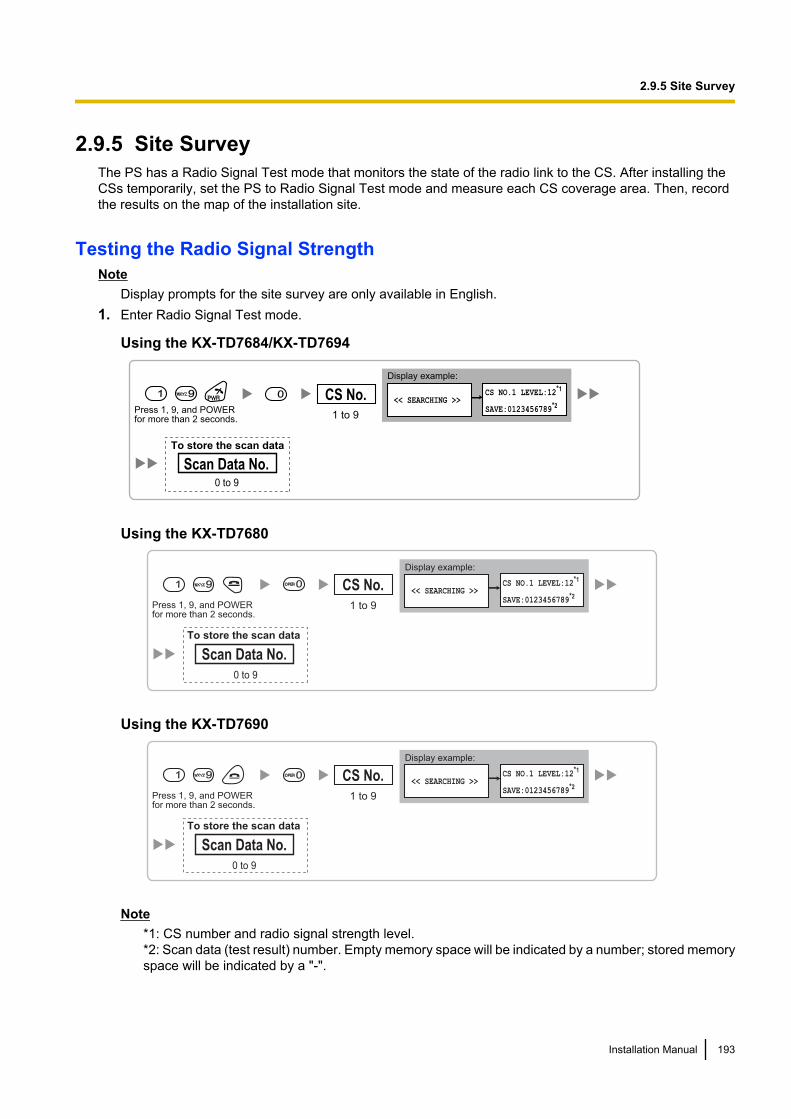
2.9.5 Site SurveyThe PS has a Radio Signal Test mode that monitors the state of the radio link to the CS. After installing theCSs temporarily, set the PS to Radio Signal Test mode and measure each CS coverage area. Then, recordthe results on the map of the installation site.
Testing the Radio Signal StrengthNote
Display prompts for the site survey are only available in English.1. Enter Radio Signal Test mode.
Using the KX-TD7684/KX-TD7694
<< SEARCHING >>CS NO.1 LEVEL:12
*1
SAVE:0123456789*2
1 99 0
Press 1, 9, and POWERfor more than 2 seconds. 1 to 9
CS No.
Scan Data No.0 to 9
Display example:
To store the scan data
Using the KX-TD7680
Display example:
Press 1, 9, and POWERfor more than 2 seconds.
<< SEARCHING >>CS NO.1 LEVEL:12
*1
SAVE:0123456789*2
1 to 9
CS No.1 99
0 to 9
Scan Data No.
To store the scan data
0
Using the KX-TD7690
Display example:
Press 1, 9, and POWERfor more than 2 seconds.
<< SEARCHING >>CS NO.1 LEVEL:12
*1
SAVE:0123456789*2
1 to 9
CS No.1 99
0 to 9
Scan Data No.
To store the scan data
0
Note*1: CS number and radio signal strength level.*2: Scan data (test result) number. Empty memory space will be indicated by a number; stored memoryspace will be indicated by a "-".
Installation Manual 193
2.9.5 Site Survey
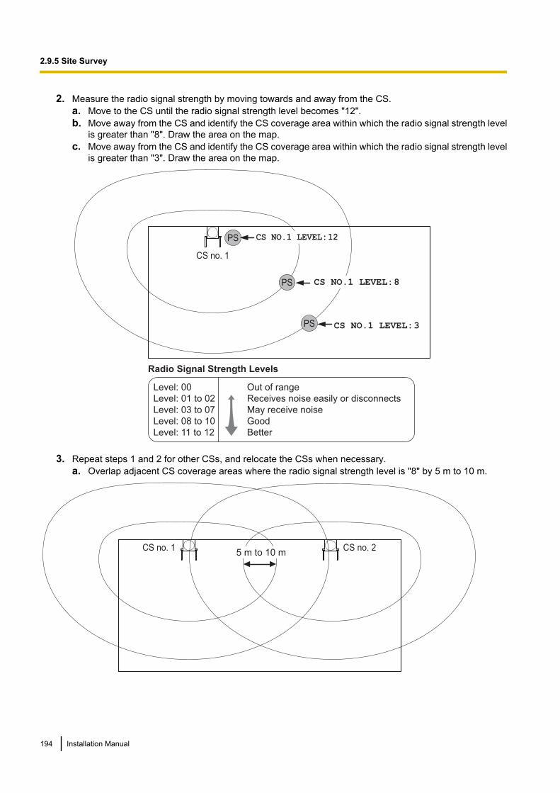
2. Measure the radio signal strength by moving towards and away from the CS.a. Move to the CS until the radio signal strength level becomes "12".b. Move away from the CS and identify the CS coverage area within which the radio signal strength level
is greater than "8". Draw the area on the map.c. Move away from the CS and identify the CS coverage area within which the radio signal strength level
is greater than "3". Draw the area on the map.
CS no. 1
PS
PS
PS CS NO.1 LEVEL:3
CS NO.1 LEVEL:12
Radio Signal Strength Levels
CS NO.1 LEVEL:8
Out of range
Receives noise easily or disconnects
May receive noise
Good
Better
Level: 00
Level: 01 to 02
Level: 03 to 07
Level: 08 to 10
Level: 11 to 12
3. Repeat steps 1 and 2 for other CSs, and relocate the CSs when necessary.a. Overlap adjacent CS coverage areas where the radio signal strength level is "8" by 5 m to 10 m.
5 m to 10 mCS no. 1 CS no. 2
194 Installation Manual
2.9.5 Site Survey
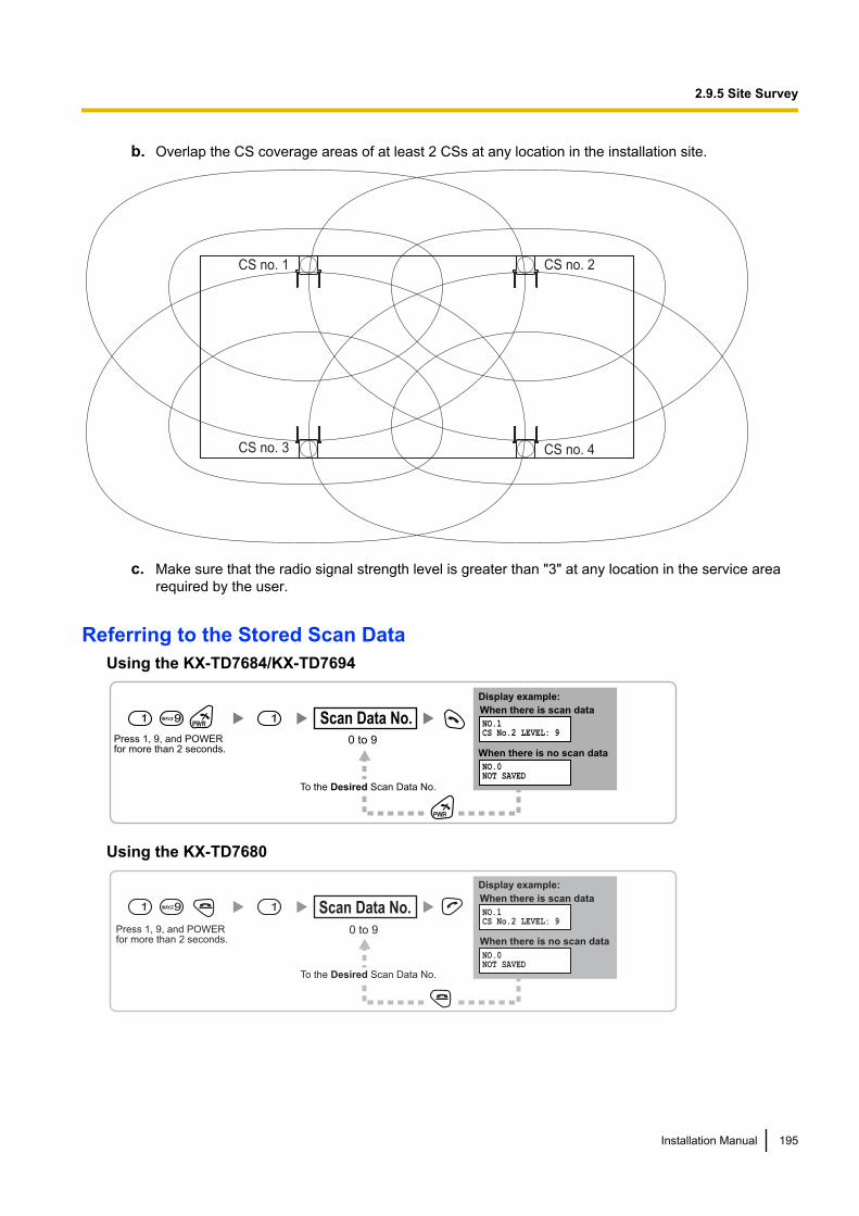
b. Overlap the CS coverage areas of at least 2 CSs at any location in the installation site.
CS no. 1 CS no. 2
CS no. 3 CS no. 4
c. Make sure that the radio signal strength level is greater than "3" at any location in the service arearequired by the user.
Referring to the Stored Scan DataUsing the KX-TD7684/KX-TD7694
1 99 1NO.1CS No.2 LEVEL: 9
NO.0NOT SAVED
Press 1, 9, and POWERfor more than 2 seconds.
0 to 9
To the Desired Scan Data No.
Scan Data No.
Display example:
When there is scan data
When there is no scan data
Using the KX-TD7680
Press 1, 9, and POWERfor more than 2 seconds.
0 to 9
Scan Data No.1 99 1
Display example:
When there is scan data
When there is no scan data
NO.1CS No.2 LEVEL: 9
NO.0NOT SAVED
To the Desired Scan Data No.
Installation Manual 195
2.9.5 Site Survey
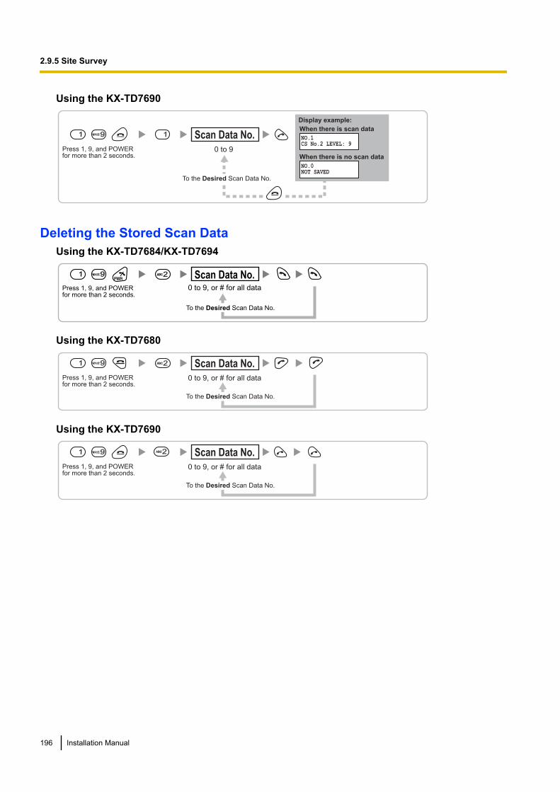
Using the KX-TD7690
Press 1, 9, and POWERfor more than 2 seconds.
0 to 9
Scan Data No.1 99 1
Display example:
When there is scan data
When there is no scan data
NO.1CS No.2 LEVEL: 9
NO.0NOT SAVED
To the Desired Scan Data No.
Deleting the Stored Scan DataUsing the KX-TD7684/KX-TD7694
1 99 22
Press 1, 9, and POWERfor more than 2 seconds.
0 to 9, or # for all data
To the Desired Scan Data No.
Scan Data No.
Using the KX-TD7680
Press 1, 9, and POWERfor more than 2 seconds.
0 to 9, or # for all data
Scan Data No.1 99
To the Desired Scan Data No.
2
Using the KX-TD7690
Press 1, 9, and POWERfor more than 2 seconds.
0 to 9, or # for all data
Scan Data No.1 99
To the Desired Scan Data No.
2
196 Installation Manual
2.9.5 Site Survey
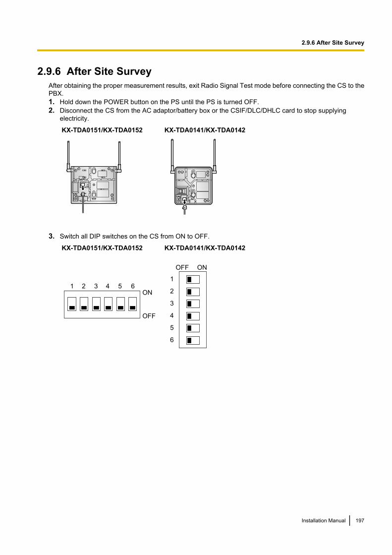
2.9.6 After Site SurveyAfter obtaining the proper measurement results, exit Radio Signal Test mode before connecting the CS to thePBX.1. Hold down the POWER button on the PS until the PS is turned OFF.2. Disconnect the CS from the AC adaptor/battery box or the CSIF/DLC/DHLC card to stop supplying
electricity.
KX-TDA0151/KX-TDA0152 KX-TDA0141/KX-TDA0142
3. Switch all DIP switches on the CS from ON to OFF.
KX-TDA0151/KX-TDA0152
1 2 3 4 5 6
OFF
ON
KX-TDA0141/KX-TDA0142
1
2
3
4
5
6
OFF ON
Installation Manual 197
2.9.6 After Site Survey
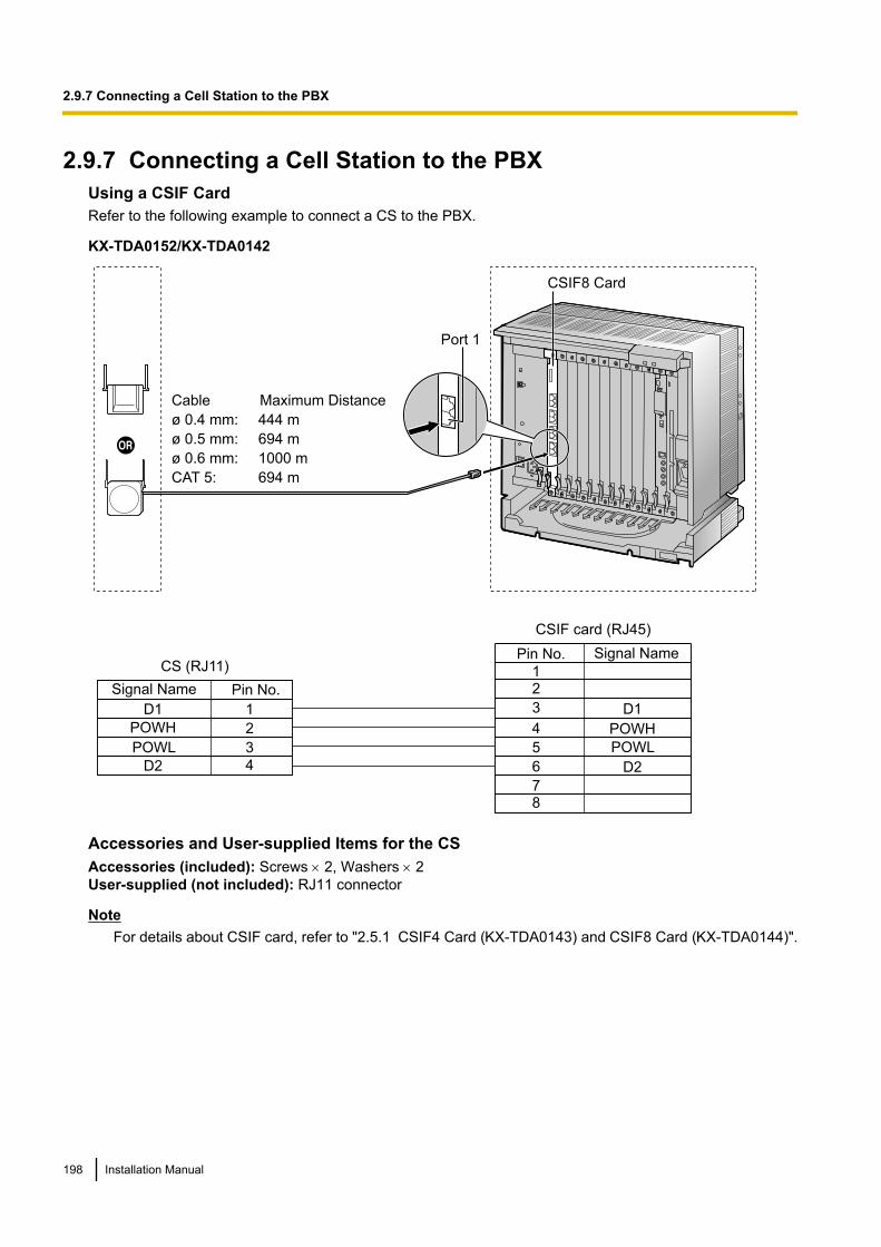
2.9.7 Connecting a Cell Station to the PBXUsing a CSIF CardRefer to the following example to connect a CS to the PBX.
KX-TDA0152/KX-TDA0142
1
2
3
4
D1
POWH
POWL
D2
D1
POWH
POWL
D2
12
3
4
5
6
78
Signal Name
Signal Name Pin No.
Pin No.
CSIF card (RJ45)
CS (RJ11)
Cable Maximum Distance
ø 0.4 mm: 444 m
ø 0.5 mm: 694 m
ø 0.6 mm: 1000 m
CAT 5: 694 m
CSIF8 Card
Port 1
Accessories and User-supplied Items for the CSAccessories (included): Screws ´ 2, Washers ´ 2User-supplied (not included): RJ11 connector
NoteFor details about CSIF card, refer to "2.5.1 CSIF4 Card (KX-TDA0143) and CSIF8 Card (KX-TDA0144)".
198 Installation Manual
2.9.7 Connecting a Cell Station to the PBX
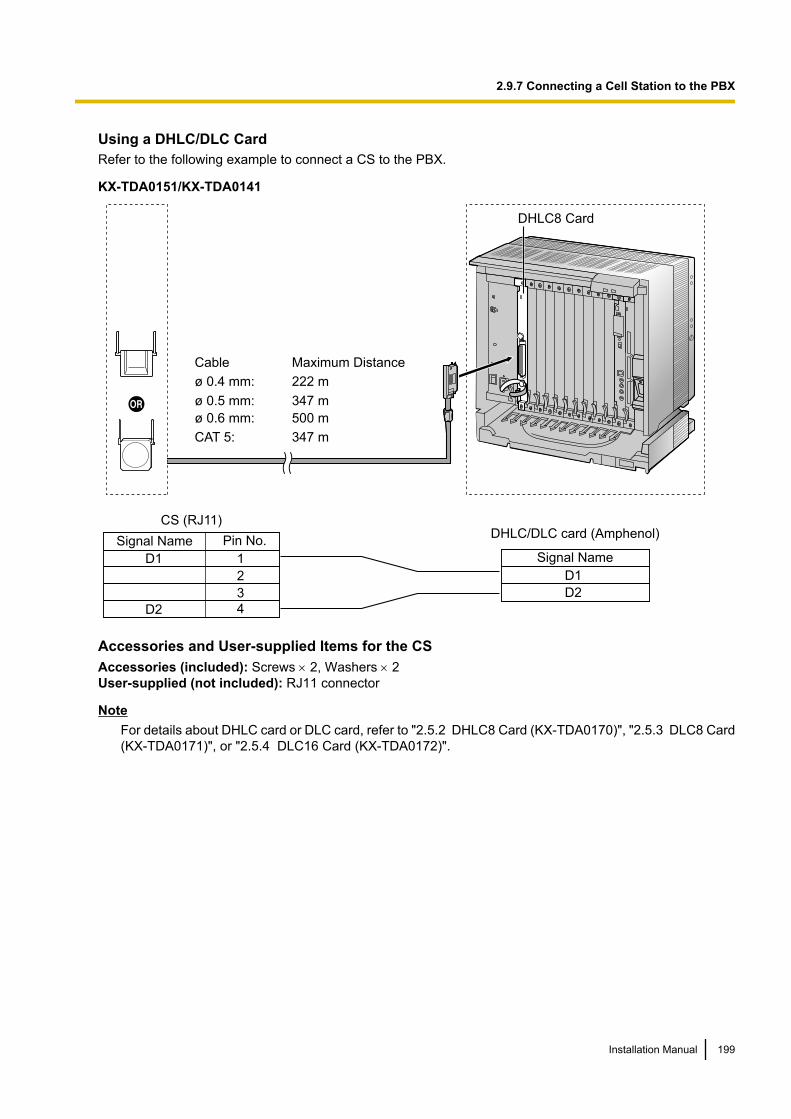
Using a DHLC/DLC CardRefer to the following example to connect a CS to the PBX.
KX-TDA0151/KX-TDA0141
Cable
ø 0.4 mm:
ø 0.5 mm:
ø 0.6 mm:
CAT 5:
Maximum Distance
222 m
347 m
500 m
347 m
D1
D2
Signal Name
DHLC/DLC card (Amphenol)
1
2
3
4
D1
D2
CS (RJ11)
Pin No.Signal Name
DHLC8 Card
Accessories and User-supplied Items for the CSAccessories (included): Screws ´ 2, Washers ´ 2User-supplied (not included): RJ11 connector
NoteFor details about DHLC card or DLC card, refer to "2.5.2 DHLC8 Card (KX-TDA0170)", "2.5.3 DLC8 Card(KX-TDA0171)", or "2.5.4 DLC16 Card (KX-TDA0172)".
Installation Manual 199
2.9.7 Connecting a Cell Station to the PBX
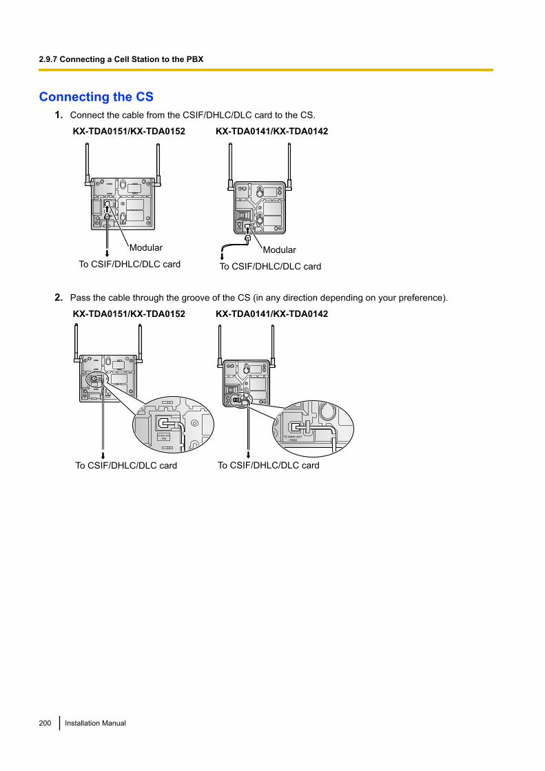
Connecting the CS1. Connect the cable from the CSIF/DHLC/DLC card to the CS.
KX-TDA0151/KX-TDA0152
Modular
To CSIF/DHLC/DLC card
KX-TDA0141/KX-TDA0142
Modular
To CSIF/DHLC/DLC card
2. Pass the cable through the groove of the CS (in any direction depending on your preference).
KX-TDA0151/KX-TDA0152
To CSIF/DHLC/DLC card
KX-TDA0141/KX-TDA0142
To CSIF/DHLC/DLC card
200 Installation Manual
2.9.7 Connecting a Cell Station to the PBX
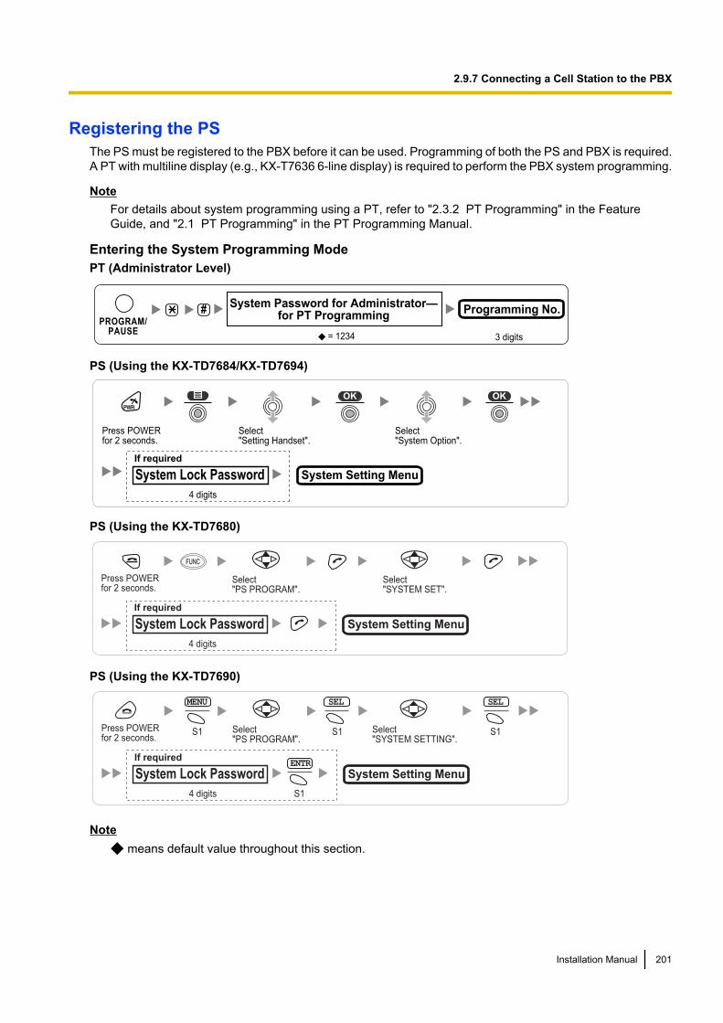
Registering the PSThe PS must be registered to the PBX before it can be used. Programming of both the PS and PBX is required.A PT with multiline display (e.g., KX-T7636 6-line display) is required to perform the PBX system programming.
NoteFor details about system programming using a PT, refer to "2.3.2 PT Programming" in the FeatureGuide, and "2.1 PT Programming" in the PT Programming Manual.
Entering the System Programming ModePT (Administrator Level)
#
= 1234
System Password for Administrator—for PT Programming
Programming No.
3 digits
PROGRAM/PAUSE
PS (Using the KX-TD7684/KX-TD7694)
Press POWERfor 2 seconds.
Select "Setting Handset".
Select "System Option".
If required
4 digits
System Lock Password System Setting Menu
PS (Using the KX-TD7680)
System Setting Menu
Select "SYSTEM SET".
Press POWER for 2 seconds.
Select"PS PROGRAM".
4 digits
System Lock Password
If required
FUNCFUNC
PS (Using the KX-TD7690)
System Setting Menu
Select "SYSTEM SETTING".
Press POWER for 2 seconds.
S1 S1
MENU SEL
S1
SEL
Select"PS PROGRAM".
4 digits
System Lock Password
If requiredENTR
S1
Note means default value throughout this section.
Installation Manual 201
2.9.7 Connecting a Cell Station to the PBX
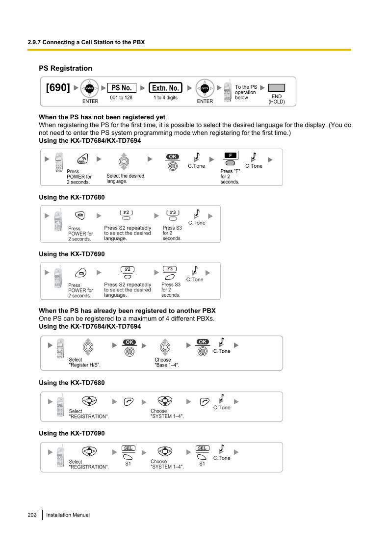
PS Registration
[690]001 to 128
PS No.1 to 4 digits END
(HOLD)ENTER ENTER
To the PSoperationbelow
Extn. No.
When the PS has not been registered yetWhen registering the PS for the first time, it is possible to select the desired language for the display. (You donot need to enter the PS system programming mode when registering for the first time.)Using the KX-TD7684/KX-TD7694
Press POWER for 2 seconds.
Select the desired language.
Press "F" for 2 seconds.
C.Tone C.Tone
Using the KX-TD7680
PressPOWER for2 seconds.
Press S3 for 2 seconds.
C.TonePress S2 repeatedly to select the desired language.
[ F2 ] [ F3 ]
Using the KX-TD7690
PressPOWER for2 seconds.
Press S3 for 2 seconds.
C.TonePress S2 repeatedlyto select the desiredlanguage.
F2 F3
When the PS has already been registered to another PBXOne PS can be registered to a maximum of 4 different PBXs.Using the KX-TD7684/KX-TD7694
Choose "Base 1–4".
Select "Register H/S".
C.Tone
Using the KX-TD7680
Choose "SYSTEM 1–4".
Select "REGISTRATION".
C.Tone
Using the KX-TD7690
Choose "SYSTEM 1–4".
Select "REGISTRATION".
S1S1
SEL SEL
C.Tone
202 Installation Manual
2.9.7 Connecting a Cell Station to the PBX
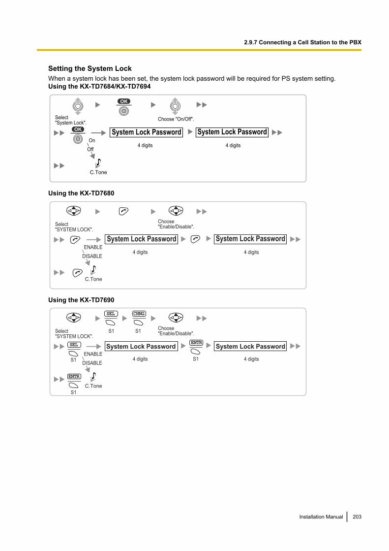
Setting the System LockWhen a system lock has been set, the system lock password will be required for PS system setting.Using the KX-TD7684/KX-TD7694
Select "System Lock".
4 digits 4 digits
Choose "On/Off".
On
Off
C.Tone
System Lock Password System Lock Password
Using the KX-TD7680
Choose "Enable/Disable".Select
"SYSTEM LOCK".
C.Tone
4 digits 4 digitsENABLE
DISABLE
System Lock Password System Lock Password
Using the KX-TD7690
S1Choose "Enable/Disable".
SEL
ENTR
S1
S1
S1
S1
CHNG
SEL
ENTR
Select "SYSTEM LOCK".
C.Tone
System Lock Password System Lock Password
4 digits 4 digitsENABLE
DISABLE
Installation Manual 203
2.9.7 Connecting a Cell Station to the PBX

Setting the Personal Identification Number (PIN) for PS RegistrationTo prevent registering the PS to a wrong PBX, a PIN for PS registration can be set to the PBX. Before registeringthe PS to the PBX, enter the PIN set to the PBX into the PS. By doing so, the PS will only be registered to thePBX with the matching PIN.
Note• By default, the PIN for PS registration is "1234" for both the PBX and PS. Therefore, the PS can be
registered to the PBX without setting the PIN.• The PIN for PS registration will only be used when registering the PS to the PBX.
Therefore, during normal operation after registration, even if there is more than 1 PBX with the samePIN near the PS, the PS will not be inadvertently linked to a different PBX.
Setting the PIN for PBX
[692]4 digits
PIN for PS RegistrationEND
(HOLD)ENTER ENTER1234
Setting the PIN for PSUsing the KX-TD7684/KX-TD7694
Select "Change PIN"
1 to 8 digits1234
C.TonePIN for PS Registration
Using the KX-TD7680
Select "CHANGE PIN"
C.Tone1 to 4 digits
1234
PIN for PS Registration
Using the KX-TD7690
Select "CHANGE PIN" S1
ENTR
S1
SEL
C.Tone1 to 4 digits
1234
PIN for PS Registration
204 Installation Manual
2.9.7 Connecting a Cell Station to the PBX
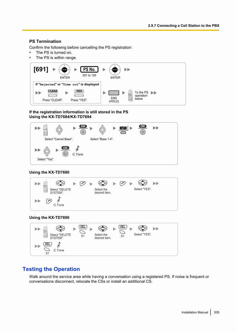
PS TerminationConfirm the following before cancelling the PS registration:• The PS is turned on.• The PS is within range.
[691]001 to 128
PS No.
ENTER ENTER
END(HOLD)
To the PSoperationbelow
If "Rejected" or "Time out" is displayed
CLEAR YES
Press "YES".Press "CLEAR".
If the registration information is still stored in the PSUsing the KX-TD7684/KX-TD7694
Select "Base 1-4".
Select "Yes".
C.Tone
Select "Cancel Base".
Using the KX-TD7680
Select the desired item.
Select "DELETESYSTEM".
Select "YES".
C.Tone
Using the KX-TD7690
Select the desired item.
Select "DELETESYSTEM".
S1S1
SEL SEL
Select "YES".
C.ToneS1
SEL
Testing the OperationWalk around the service area while having a conversation using a registered PS. If noise is frequent orconversations disconnect, relocate the CSs or install an additional CS.
Installation Manual 205
2.9.7 Connecting a Cell Station to the PBX
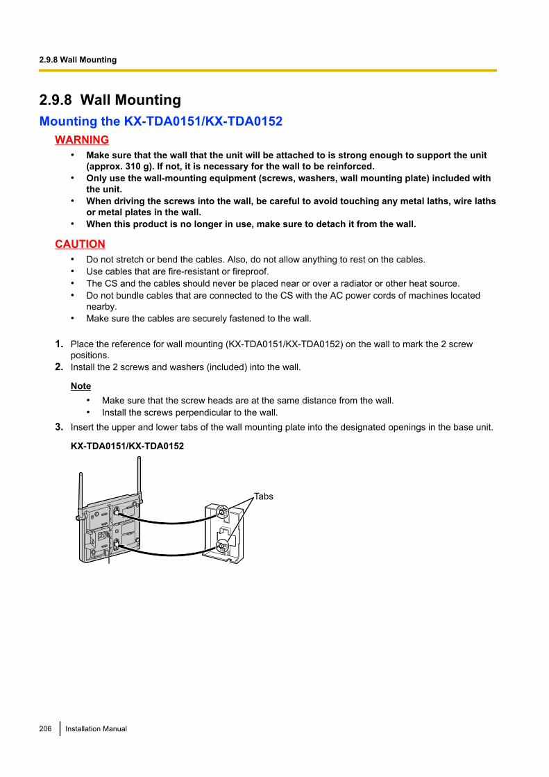
2.9.8 Wall MountingMounting the KX-TDA0151/KX-TDA0152
WARNING• Make sure that the wall that the unit will be attached to is strong enough to support the unit
(approx. 310 g). If not, it is necessary for the wall to be reinforced.• Only use the wall-mounting equipment (screws, washers, wall mounting plate) included with
the unit.• When driving the screws into the wall, be careful to avoid touching any metal laths, wire laths
or metal plates in the wall.• When this product is no longer in use, make sure to detach it from the wall.
CAUTION• Do not stretch or bend the cables. Also, do not allow anything to rest on the cables.• Use cables that are fire-resistant or fireproof.• The CS and the cables should never be placed near or over a radiator or other heat source.• Do not bundle cables that are connected to the CS with the AC power cords of machines located
nearby.• Make sure the cables are securely fastened to the wall.
1. Place the reference for wall mounting (KX-TDA0151/KX-TDA0152) on the wall to mark the 2 screwpositions.
2. Install the 2 screws and washers (included) into the wall.
Note• Make sure that the screw heads are at the same distance from the wall.• Install the screws perpendicular to the wall.
3. Insert the upper and lower tabs of the wall mounting plate into the designated openings in the base unit.
KX-TDA0151/KX-TDA0152
Tabs
206 Installation Manual
2.9.8 Wall Mounting
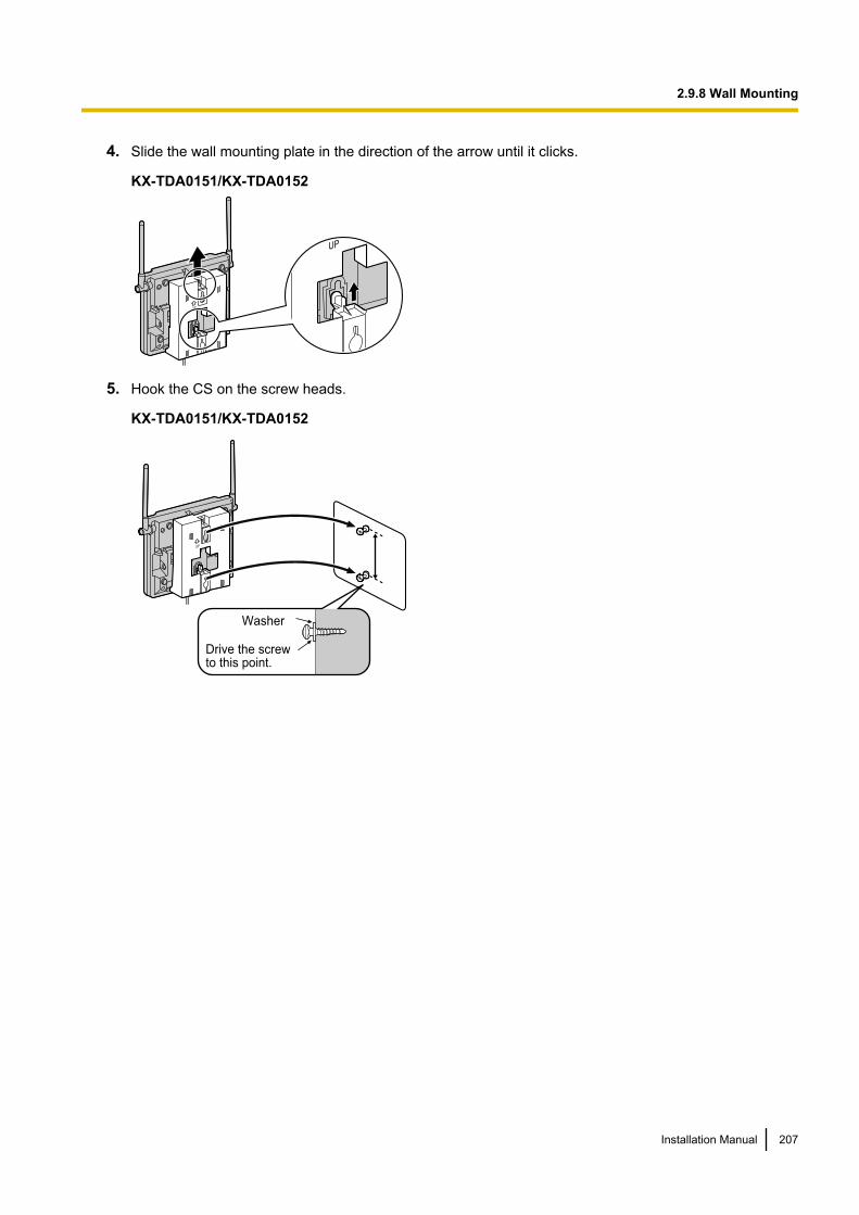
4. Slide the wall mounting plate in the direction of the arrow until it clicks.
KX-TDA0151/KX-TDA0152
5. Hook the CS on the screw heads.
KX-TDA0151/KX-TDA0152
Washer
Drive the screw to this point.
Installation Manual 207
2.9.8 Wall Mounting
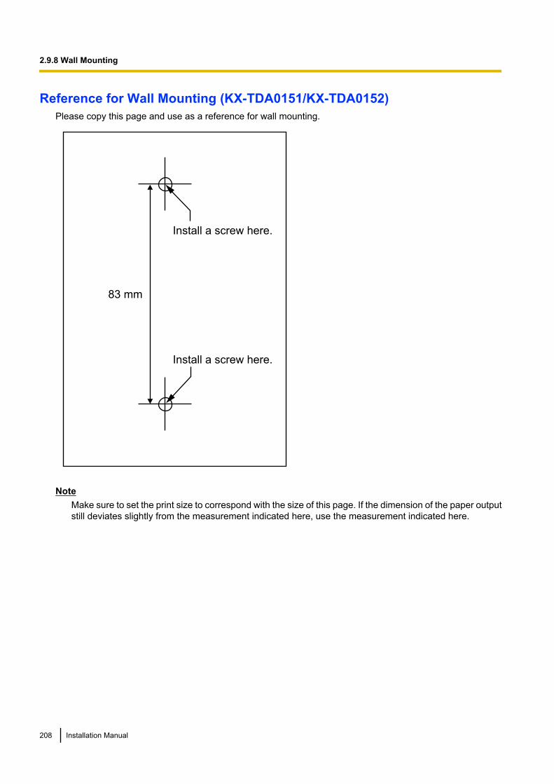
Reference for Wall Mounting (KX-TDA0151/KX-TDA0152)Please copy this page and use as a reference for wall mounting.
Install a screw here.
Install a screw here.
83 mm
NoteMake sure to set the print size to correspond with the size of this page. If the dimension of the paper outputstill deviates slightly from the measurement indicated here, use the measurement indicated here.
208 Installation Manual
2.9.8 Wall Mounting

Mounting the KX-TDA0141/KX-TDA0142WARNING
• Make sure that the wall that the unit will be attached to is strong enough to support the unit(approx. 310 g). If not, it is necessary for the wall to be reinforced.
• Only use the wall-mounting equipment (screws, washers) included with the unit.• When driving the screws into the wall, be careful to avoid touching any metal laths, wire laths
or metal plates in the wall.• When this product is no longer in use, make sure to detach it from the wall.
CAUTION• Do not stretch or bend the cables. Also, do not allow anything to rest on the cables.• Use cables that are fire-resistant or fireproof.• The CS and the cables should never be placed near or over a radiator or other heat source.• Do not bundle cables that are connected to the CS with the AC power cords of machines located
nearby.• Make sure the cables are securely fastened to the wall.
1. Place the reference for wall mounting (KX-TDA0141/KX-TDA0142) on the wall to mark the 2 screwpositions.
2. Install the 2 screws and washers (included) into the wall.
Note• Make sure that the screw heads are at the same distance from the wall.• Install the screws perpendicular to the wall.
3. Hook the CS on the screw heads.
Washer
Drive the screw to this point.
Installation Manual 209
2.9.8 Wall Mounting
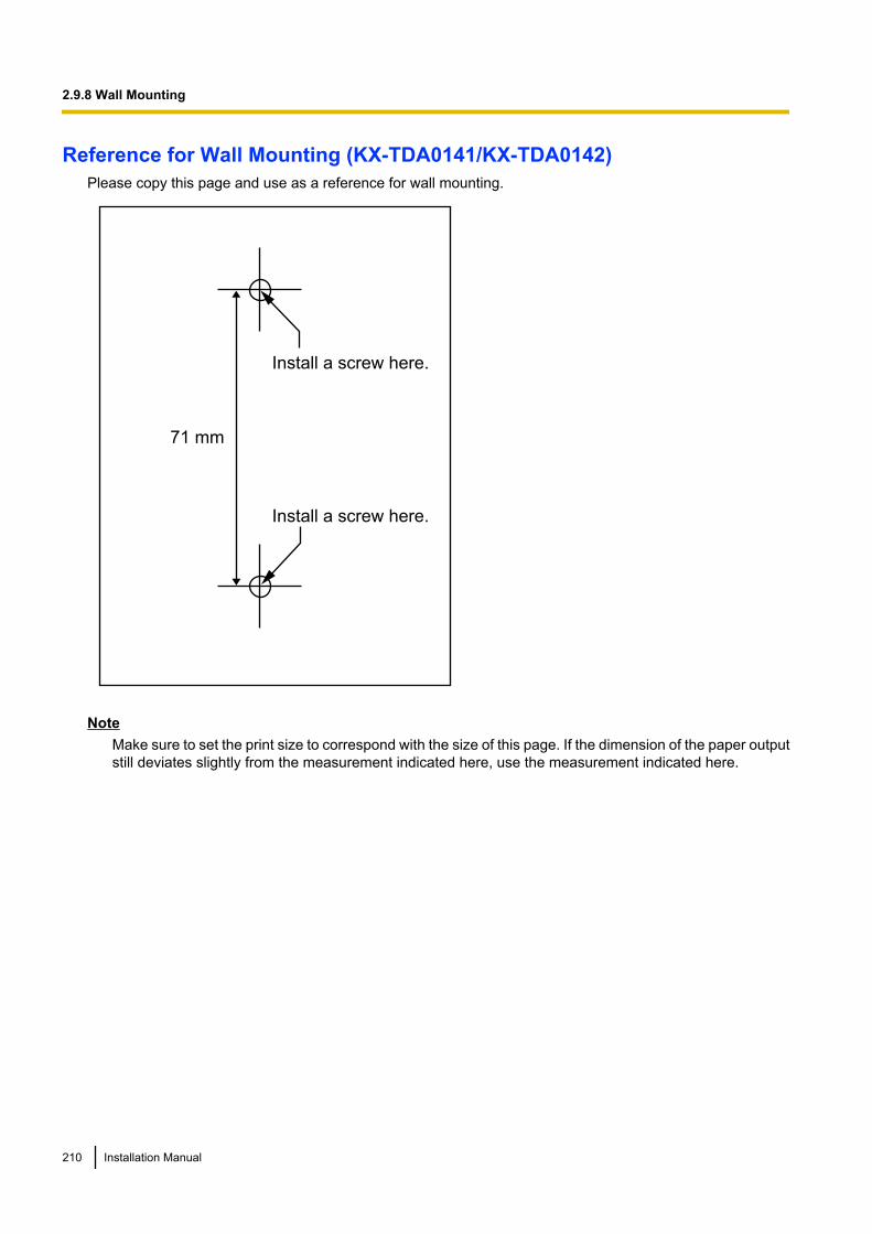
Reference for Wall Mounting (KX-TDA0141/KX-TDA0142)Please copy this page and use as a reference for wall mounting.
Install a screw here.
Install a screw here.
71 mm
NoteMake sure to set the print size to correspond with the size of this page. If the dimension of the paper outputstill deviates slightly from the measurement indicated here, use the measurement indicated here.
210 Installation Manual
2.9.8 Wall Mounting

2.10 Connection of DECT 6.0 Portable Stations
2.10.1 OverviewNames and Locations of CS
LED
Antennas
CS ID Number
(ID: xxxxxxxxxx)
LED IndicationsIndication Colour Description
STATUS Green/Red CS status indication• OFF: Power Off• Green ON: Stand-by (no active calls)• Slow Green Flashing (60 times per minute): Talk (active calls)• Moderate Green Flashing (120 times per minute): Busy• Red ON: Fault (includes Initialisation)• Red Flashing (60 times per minute): Out of Service/Starting up
CS status indication during the site survey• Red ON: The CS is connected to an AC adaptor/battery box.• Red Flashing (60 times per minute): The CS is connected to the
PBX.
Required Equipment and Maximum Number of CallsCSs determine the area covered by the wireless system. The number of calls that can be made simultaneouslythrough each CS varies depending on the model, as follows:
CS Connection Card Maximum Calls Compatible PSs
KX-TDA0155 DHLC/DLC 2 • KX-TD7685• KX-TD7695KX-TDA0158 DHLC/DLC 8
NoteFor more details about the PS, refer to the Operating Instructions of the PS.
Installation Manual 211
2.10.1 Overview
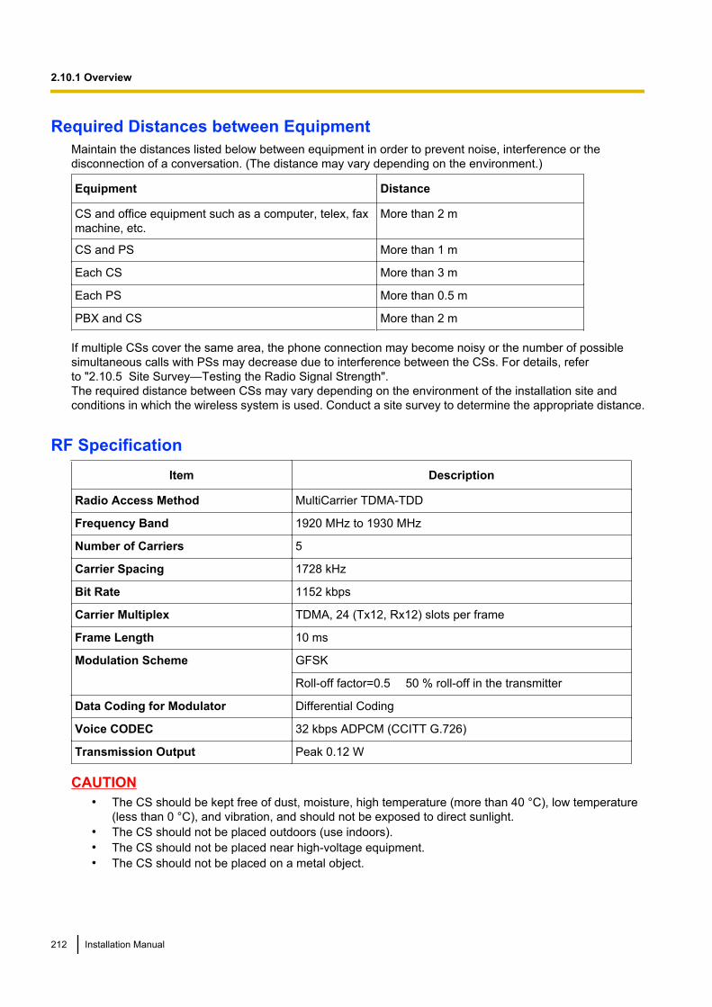
Required Distances between EquipmentMaintain the distances listed below between equipment in order to prevent noise, interference or thedisconnection of a conversation. (The distance may vary depending on the environment.)
Equipment Distance
CS and office equipment such as a computer, telex, faxmachine, etc.
More than 2 m
CS and PS More than 1 m
Each CS More than 3 m
Each PS More than 0.5 m
PBX and CS More than 2 m
If multiple CSs cover the same area, the phone connection may become noisy or the number of possiblesimultaneous calls with PSs may decrease due to interference between the CSs. For details, referto "2.10.5 Site Survey—Testing the Radio Signal Strength".The required distance between CSs may vary depending on the environment of the installation site andconditions in which the wireless system is used. Conduct a site survey to determine the appropriate distance.
RF SpecificationItem Description
Radio Access Method MultiCarrier TDMA-TDD
Frequency Band 1920 MHz to 1930 MHz
Number of Carriers 5
Carrier Spacing 1728 kHz
Bit Rate 1152 kbps
Carrier Multiplex TDMA, 24 (Tx12, Rx12) slots per frame
Frame Length 10 ms
Modulation Scheme GFSK
Roll-off factor=0.5 50 % roll-off in the transmitter
Data Coding for Modulator Differential Coding
Voice CODEC 32 kbps ADPCM (CCITT G.726)
Transmission Output Peak 0.12 W
CAUTION• The CS should be kept free of dust, moisture, high temperature (more than 40 °C), low temperature
(less than 0 °C), and vibration, and should not be exposed to direct sunlight.• The CS should not be placed outdoors (use indoors).• The CS should not be placed near high-voltage equipment.• The CS should not be placed on a metal object.
212 Installation Manual
2.10.1 Overview
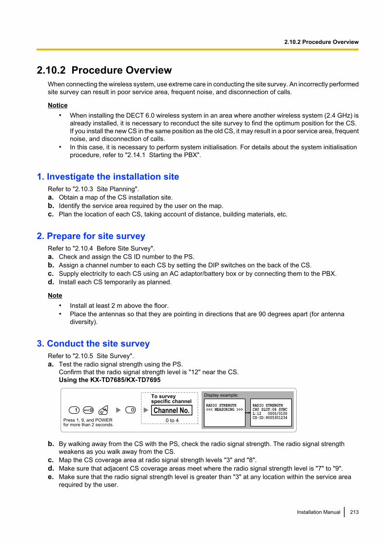
2.10.2 Procedure OverviewWhen connecting the wireless system, use extreme care in conducting the site survey. An incorrectly performedsite survey can result in poor service area, frequent noise, and disconnection of calls.
Notice• When installing the DECT 6.0 wireless system in an area where another wireless system (2.4 GHz) is
already installed, it is necessary to reconduct the site survey to find the optimum position for the CS.If you install the new CS in the same position as the old CS, it may result in a poor service area, frequentnoise, and disconnection of calls.
• In this case, it is necessary to perform system initialisation. For details about the system initialisationprocedure, refer to "2.14.1 Starting the PBX".
1. Investigate the installation siteRefer to "2.10.3 Site Planning".a. Obtain a map of the CS installation site.b. Identify the service area required by the user on the map.c. Plan the location of each CS, taking account of distance, building materials, etc.
2. Prepare for site surveyRefer to "2.10.4 Before Site Survey".a. Check and assign the CS ID number to the PS.b. Assign a channel number to each CS by setting the DIP switches on the back of the CS.c. Supply electricity to each CS using an AC adaptor/battery box or by connecting them to the PBX.d. Install each CS temporarily as planned.
Note• Install at least 2 m above the floor.• Place the antennas so that they are pointing in directions that are 90 degrees apart (for antenna
diversity).
3. Conduct the site surveyRefer to "2.10.5 Site Survey".a. Test the radio signal strength using the PS.
Confirm that the radio signal strength level is "12" near the CS.Using the KX-TD7685/KX-TD7695
Display example:
RADIO STRENGTH<<< MEASURING >>>
RADIO STRENGTHCH0 SLOT:06 SYNCL:12 0000/0100CS-ID:9005301234
Press 1, 9, and POWERfor more than 2 seconds.
1 99 0
0 to 4
Channel No.
To surveyspecific channel
b. By walking away from the CS with the PS, check the radio signal strength. The radio signal strengthweakens as you walk away from the CS.
c. Map the CS coverage area at radio signal strength levels "3" and "8".d. Make sure that adjacent CS coverage areas meet where the radio signal strength level is "7" to "9".e. Make sure that the radio signal strength level is greater than "3" at any location within the service area
required by the user.
Installation Manual 213
2.10.2 Procedure Overview
4. Finish the site surveyRefer to "2.10.6 After Site Survey".a. Turn off the PS.b. Stop supplying power, and return all DIP switches of each CS to the OFF position.
5. Connect the CS and PS to the PBX and test the operationRefer to "2.10.7 Connecting a Cell Station to the PBX".a. Connect the CSs to the PBX.b. Register the PSs to the PBX.c. Walk around the service area while having a conversation using a registered PS. If noise is frequent or
conversations disconnect, relocate the CSs or install an additional CS.
6. Mount the CS on the wallRefer to "2.10.8 Wall Mounting".a. If there are no problems in testing, mount the CS on the wall.
214 Installation Manual
2.10.2 Procedure Overview
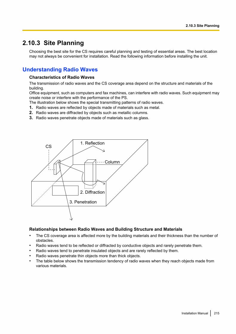
2.10.3 Site PlanningChoosing the best site for the CS requires careful planning and testing of essential areas. The best locationmay not always be convenient for installation. Read the following information before installing the unit.
Understanding Radio WavesCharacteristics of Radio WavesThe transmission of radio waves and the CS coverage area depend on the structure and materials of thebuilding.Office equipment, such as computers and fax machines, can interfere with radio waves. Such equipment maycreate noise or interfere with the performance of the PS.The illustration below shows the special transmitting patterns of radio waves.1. Radio waves are reflected by objects made of materials such as metal.2. Radio waves are diffracted by objects such as metallic columns.3. Radio waves penetrate objects made of materials such as glass.
CS
Column
3. Penetration
2. Diffraction
1. Reflection
Relationships between Radio Waves and Building Structure and Materials• The CS coverage area is affected more by the building materials and their thickness than the number of
obstacles.• Radio waves tend to be reflected or diffracted by conductive objects and rarely penetrate them.• Radio waves tend to penetrate insulated objects and are rarely reflected by them.• Radio waves penetrate thin objects more than thick objects.• The table below shows the transmission tendency of radio waves when they reach objects made from
various materials.
Installation Manual 215
2.10.3 Site Planning
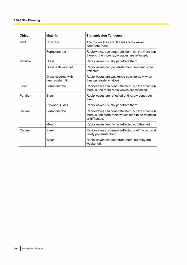
Object Material Transmission Tendency
Wall Concrete The thicker they are, the less radio wavespenetrate them.
Ferroconcrete Radio waves can penetrate them, but the more ironthere is, the more radio waves are reflected.
Window Glass Radio waves usually penetrate them.
Glass with wire net Radio waves can penetrate them, but tend to bereflected.
Glass covered withheatresistant film
Radio waves are weakened considerably whenthey penetrate windows.
Floor Ferroconcrete Radio waves can penetrate them, but the more ironthere is, the more radio waves are reflected.
Partition Steel Radio waves are reflected and rarely penetratethem.
Plywood, Glass Radio waves usually penetrate them.
Column Ferroconcrete Radio waves can penetrate them, but the more ironthere is, the more radio waves tend to be reflectedor diffracted.
Metal Radio waves tend to be reflected or diffracted.
Cabinet Steel Radio waves are usually reflected or diffracted, andrarely penetrate them.
Wood Radio waves can penetrate them, but they areweakened.
216 Installation Manual
2.10.3 Site Planning
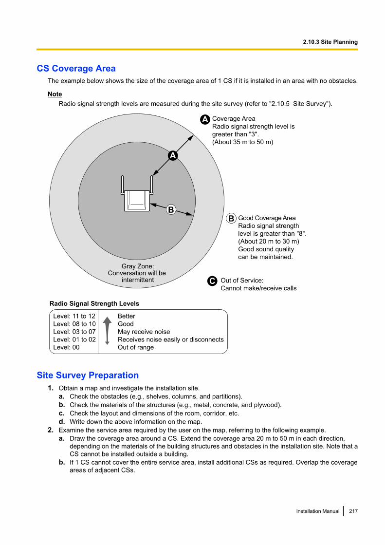
CS Coverage AreaThe example below shows the size of the coverage area of 1 CS if it is installed in an area with no obstacles.
NoteRadio signal strength levels are measured during the site survey (refer to "2.10.5 Site Survey").
A
B
A
B
C
Gray Zone:Conversation will be
intermittent Out of Service:
Cannot make/receive calls
Good Coverage Area
Radio signal strength
level is greater than "8".
(About 20 m to 30 m)
Good sound quality
can be maintained.
Coverage Area
Radio signal strength level is
greater than "3".
(About 35 m to 50 m)
Radio Signal Strength Levels
Better
Good
May receive noise
Receives noise easily or disconnects
Out of range
Level: 11 to 12
Level: 08 to 10
Level: 03 to 07
Level: 01 to 02
Level: 00
Site Survey Preparation1. Obtain a map and investigate the installation site.
a. Check the obstacles (e.g., shelves, columns, and partitions).b. Check the materials of the structures (e.g., metal, concrete, and plywood).c. Check the layout and dimensions of the room, corridor, etc.d. Write down the above information on the map.
2. Examine the service area required by the user on the map, referring to the following example.a. Draw the coverage area around a CS. Extend the coverage area 20 m to 50 m in each direction,
depending on the materials of the building structures and obstacles in the installation site. Note that aCS cannot be installed outside a building.
b. If 1 CS cannot cover the entire service area, install additional CSs as required. Overlap the coverageareas of adjacent CSs.
Installation Manual 217
2.10.3 Site Planning
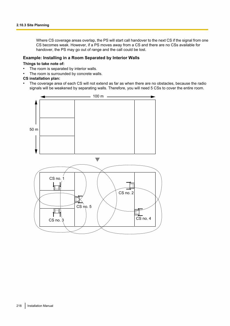
Where CS coverage areas overlap, the PS will start call handover to the next CS if the signal from oneCS becomes weak. However, if a PS moves away from a CS and there are no CSs available forhandover, the PS may go out of range and the call could be lost.
Example: Installing in a Room Separated by Interior WallsThings to take note of:• The room is separated by interior walls.• The room is surrounded by concrete walls.CS installation plan:• The coverage area of each CS will not extend as far as when there are no obstacles, because the radio
signals will be weakened by separating walls. Therefore, you will need 5 CSs to cover the entire room.
100 m
50 m
CS no. 1
CS no. 2
CS no. 4
CS no. 5
CS no. 3
218 Installation Manual
2.10.3 Site Planning

2.10.4 Before Site SurveyUse the KX-TD7685/KX-TD7695 PS to conduct the site survey.
NoteDisplay prompts for the site survey are only available in English.
Checking the CS ID NumberCheck the CS ID number label attached to the CS. If the CS ID number label is not attached to the CS, checkthe CS ID number using the Maintenance Console. For details, refer to "2.6.14 Utility—CS Information" in thePC Programming Manual.
Assigning the CS ID Number to the PSUsing the KX-TD7685/KX-TD7695
Press 1, 9, and POWERfor more than 2 seconds.
0 to 7 0 to 9 and A to F
CS No. CS ID No.1 99 2ABC
To enter letters
A: + C: + E: +
B: + D: + F: +
To the initial display To the Desired CS No.
3DEF
4GHI0
1 5JKL
2ABC
NoteTo clear the CS ID number assigned to the PS, follow the procedure below:
Press 1, 9, and POWERfor more than 2 seconds.
0 to 7
CS No.
1 99 3DEF
To the Desired CS No.
OR
#
To clear one by one
To clear all at onceTo the initial display
Setting and Installing the CS Temporarily for Site Survey1. Switch the Radio Signal Test switch from OFF to ON.2. Set the channel number switches as desired.3. Set the Power Supply Select switch as desired.
Installation Manual 219
2.10.4 Before Site Survey
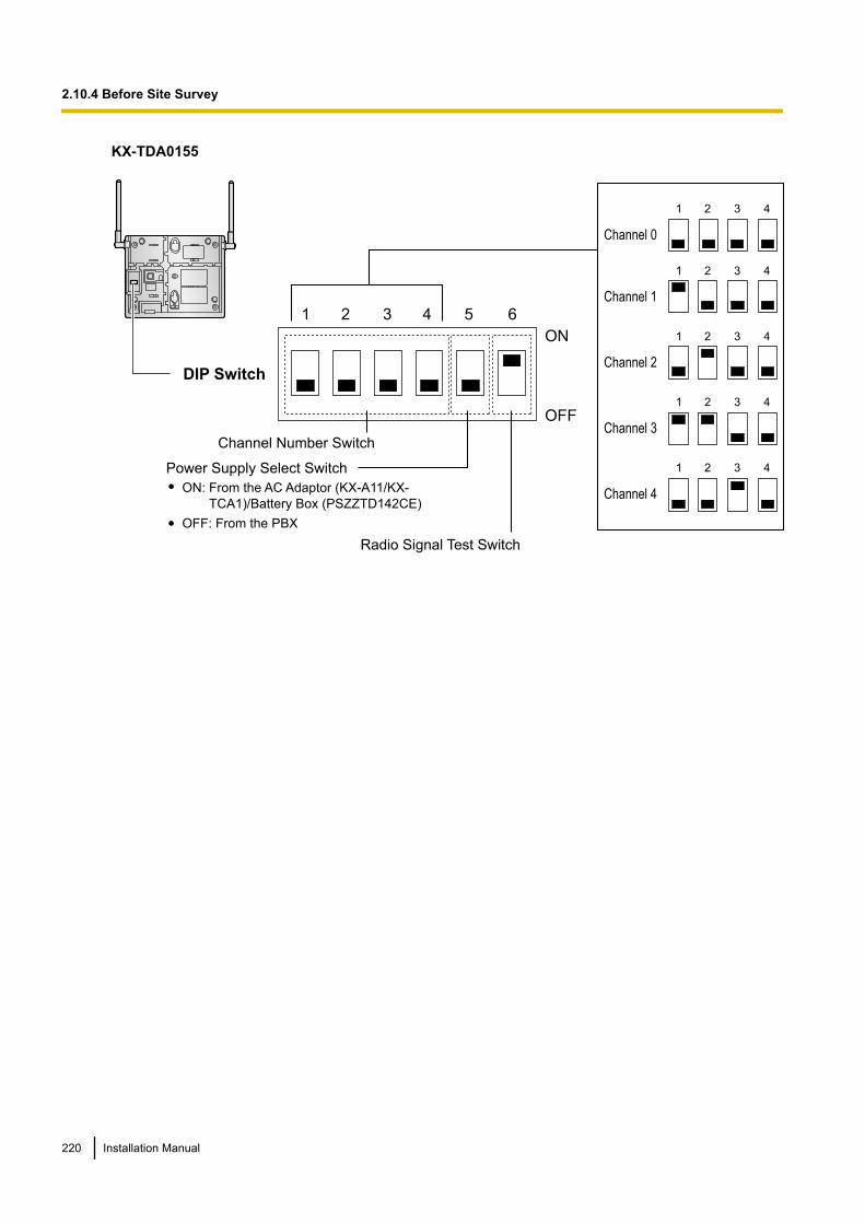
KX-TDA0155
1 2 3 4 5 6
4
4
4
4
3
3
3
3
2
2
2
2
1
1
1
1
4321
Channel 1
Channel 0
Channel 2
Channel 3
Channel 4
DIP Switch
Radio Signal Test Switch
Power Supply Select Switch
Channel Number Switch
OFF
ON
ON: From the AC Adaptor (KX-A11/KX-
TCA1)/Battery Box (PSZZTD142CE)
OFF: From the PBX
220 Installation Manual
2.10.4 Before Site Survey

KX-TDA0158
6
5
4
3
2
1
4
3
2
1
4
3
2
1
4
3
2
1
4
3
2
1
4
3
2
1
DIP Switch
Radio Signal Test Switch
Power Supply Select Switch
Channel Number Switch
Channel 1 Channel 2 Channel 3 Channel 4Channel 0
ON OFF
ON: From the AC Adaptor (KX-A11)/
Battery Box (PSZZTD142CE)
OFF: From the PBX
NoteIf more than 1 CS is in Radio Signal Test mode, each CS must have a unique channel number.
4. After setting the DIP switches, connect the CS to an AC adaptor/battery box using a power supply adaptor,or connect it to the PBX.
WARNINGThe AC adaptor should be connected to a vertically oriented or floor-mounted AC outlet. Do notconnect the AC adaptor to a ceiling-mounted AC outlet, as the weight of the adaptor may causeit to become disconnected.
Notice• When using the KX-TDA0158, it is NOT recommended to conduct the site survey using the battery
box.• If the Power Supply Select switch is set to ON in step 3, connect the CS to an AC adaptor/battery
box. If it is set to OFF, connect the CS to the PBX.
Installation Manual 221
2.10.4 Before Site Survey
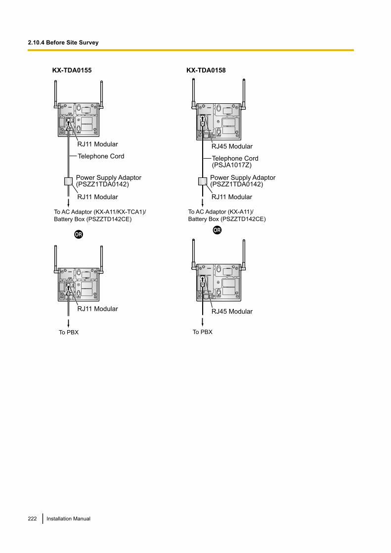
KX-TDA0155
To AC Adaptor (KX-A11/KX-TCA1)/
Battery Box (PSZZTD142CE)
Power Supply Adaptor(PSZZ1TDA0142)
RJ11 Modular
RJ11 Modular
Telephone Cord
To PBX
RJ11 Modular
KX-TDA0158
RJ45 Modular
To AC Adaptor (KX-A11)/
Battery Box (PSZZTD142CE)
To PBX
Power Supply Adaptor(PSZZ1TDA0142)
RJ45 Modular
Telephone Cord(PSJA1017Z)
RJ11 Modular
222 Installation Manual
2.10.4 Before Site Survey
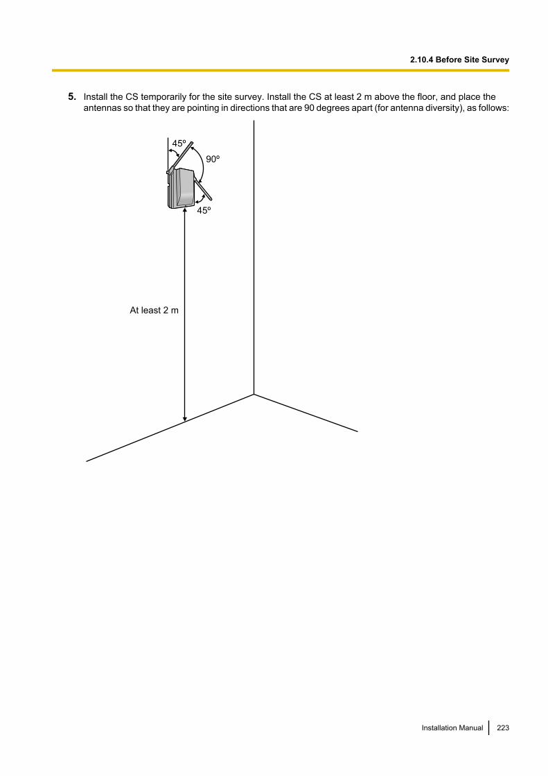
5. Install the CS temporarily for the site survey. Install the CS at least 2 m above the floor, and place theantennas so that they are pointing in directions that are 90 degrees apart (for antenna diversity), as follows:
At least 2 m
45º
45º
90º
Installation Manual 223
2.10.4 Before Site Survey
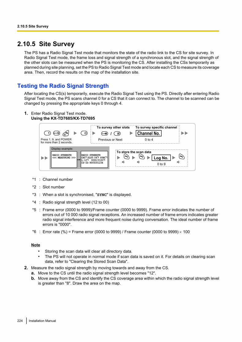
2.10.5 Site SurveyThe PS has a Radio Signal Test mode that monitors the state of the radio link to the CS for site survey. InRadio Signal Test mode, the frame loss and signal strength of a synchronous slot, and the signal strength ofthe other slots can be measured when the PS is monitoring the CS. After installing the CSs temporarily asplanned during site planning, set the PS to Radio Signal Test mode and locate each CS to measure its coveragearea. Then, record the results on the map of the installation site.
Testing the Radio Signal StrengthAfter locating the CS(s) temporarily, execute the Radio Signal Test using the PS. Directly after entering RadioSignal Test mode, the PS scans channel 0 for a CS that it can connect to. The channel to be scanned can bechanged by pressing the appropriate keys 0 through 4.
1. Enter Radio Signal Test mode.Using the KX-TD7685/KX-TD7695
0 to 9
Log No.
To store the scan data
Press 1, 9, and POWERfor more than 2 seconds.
1 99
Previous or Next 0 to 4
Channel No.
To survey other slots To survey specific channel
/
RADIO STRENGTH<<< MEASURING >>>
RADIO STRENGTHCH0*1 SLOT:06*2 SYNC*3
L:12*4 0000/0100*5
CS-ID:9005301234
0
Display example:
*1 : Channel number
*2 : Slot number
*3 : When a slot is synchronised, "SYNC" is displayed.
*4 : Radio signal strength level (12 to 00)
*5 : Frame error (0000 to 9999)/Frame counter (0000 to 9999). Frame error indicates the number oferrors out of 10 000 radio signal receptions. An increased number of frame errors indicates greaterradio signal interference and more frequent noise during conversation. The ideal number of frameerrors is "0000".
*6 : Error rate (%) = Frame error (0000 to 9999) / Frame counter (0000 to 9999) ´ 100
Note• Storing the scan data will clear all directory data.• The PS will not operate in normal mode if scan data is saved on it. For details on clearing scan
data, refer to "Clearing the Stored Scan Data".2. Measure the radio signal strength by moving towards and away from the CS.
a. Move to the CS until the radio signal strength level becomes "12".b. Move away from the CS and identify the CS coverage area within which the radio signal strength level
is greater than "8". Draw the area on the map.
224 Installation Manual
2.10.5 Site Survey
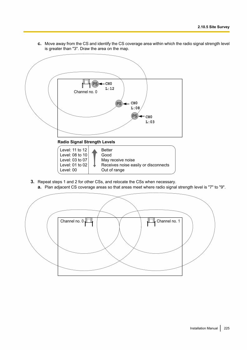
c. Move away from the CS and identify the CS coverage area within which the radio signal strength levelis greater than "3". Draw the area on the map.
PS
PS
PS
Channel no. 0
CH0
L:03
CH0
L:12
Radio Signal Strength Levels
Better
Good
May receive noise
Receives noise easily or disconnects
Out of range
Level: 11 to 12
Level: 08 to 10
Level: 03 to 07
Level: 01 to 02
Level: 00
CH0
L:08
3. Repeat steps 1 and 2 for other CSs, and relocate the CSs when necessary.a. Plan adjacent CS coverage areas so that areas meet where radio signal strength level is "7" to "9".
Channel no. 0 Channel no. 1
Installation Manual 225
2.10.5 Site Survey
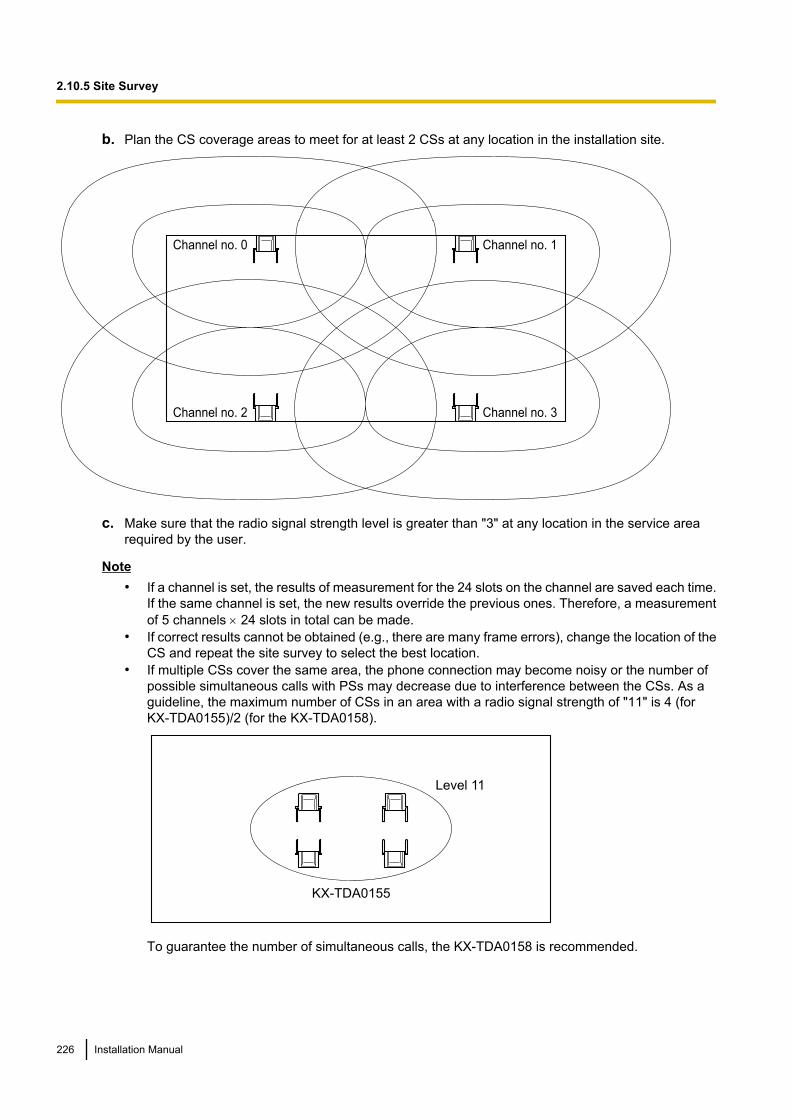
b. Plan the CS coverage areas to meet for at least 2 CSs at any location in the installation site.
Channel no. 0 Channel no. 1
Channel no. 2 Channel no. 3
c. Make sure that the radio signal strength level is greater than "3" at any location in the service arearequired by the user.
Note• If a channel is set, the results of measurement for the 24 slots on the channel are saved each time.
If the same channel is set, the new results override the previous ones. Therefore, a measurementof 5 channels ´ 24 slots in total can be made.
• If correct results cannot be obtained (e.g., there are many frame errors), change the location of theCS and repeat the site survey to select the best location.
• If multiple CSs cover the same area, the phone connection may become noisy or the number ofpossible simultaneous calls with PSs may decrease due to interference between the CSs. As aguideline, the maximum number of CSs in an area with a radio signal strength of "11" is 4 (forKX-TDA0155)/2 (for the KX-TDA0158).
Level 11
KX-TDA0155
To guarantee the number of simultaneous calls, the KX-TDA0158 is recommended.
226 Installation Manual
2.10.5 Site Survey
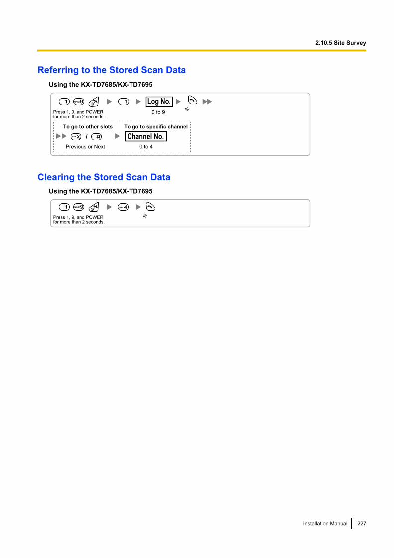
Referring to the Stored Scan DataUsing the KX-TD7685/KX-TD7695
Press 1, 9, and POWERfor more than 2 seconds.
0 to 9
Log No.1 99 1
Previous or Next 0 to 4
Channel No.
To go to other slots To go to specific channel
/A a
Clearing the Stored Scan DataUsing the KX-TD7685/KX-TD7695
Press 1, 9, and POWERfor more than 2 seconds.
1 99 4GHI
Installation Manual 227
2.10.5 Site Survey
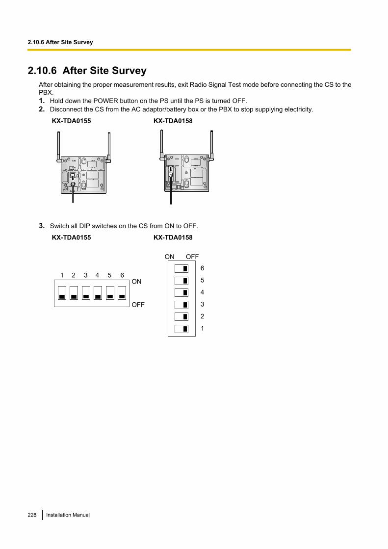
2.10.6 After Site SurveyAfter obtaining the proper measurement results, exit Radio Signal Test mode before connecting the CS to thePBX.1. Hold down the POWER button on the PS until the PS is turned OFF.2. Disconnect the CS from the AC adaptor/battery box or the PBX to stop supplying electricity.
KX-TDA0155 KX-TDA0158
3. Switch all DIP switches on the CS from ON to OFF.
KX-TDA0155
1 2 3 4 5 6
OFF
ON
KX-TDA0158
6
5
4
3
2
1
ON OFF
228 Installation Manual
2.10.6 After Site Survey
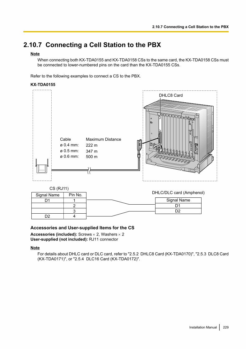
2.10.7 Connecting a Cell Station to the PBXNote
When connecting both KX-TDA0155 and KX-TDA0158 CSs to the same card, the KX-TDA0158 CSs mustbe connected to lower-numbered pins on the card than the KX-TDA0155 CSs.
Refer to the following examples to connect a CS to the PBX.
KX-TDA0155
D1
D2
Signal Name
DHLC/DLC card (Amphenol)
1
2
3
4
D1
D2
CS (RJ11)
Pin No.Signal Name
Maximum Distance
222 m
347 m
500 m
Cable
ø 0.4 mm:
ø 0.5 mm:
ø 0.6 mm:
DHLC8 Card
Accessories and User-supplied Items for the CSAccessories (included): Screws ´ 2, Washers ´ 2User-supplied (not included): RJ11 connector
NoteFor details about DHLC card or DLC card, refer to "2.5.2 DHLC8 Card (KX-TDA0170)", "2.5.3 DLC8 Card(KX-TDA0171)", or "2.5.4 DLC16 Card (KX-TDA0172)".
Installation Manual 229
2.10.7 Connecting a Cell Station to the PBX
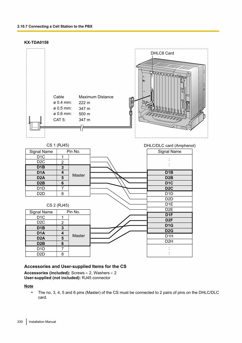
KX-TDA0158
D1B
D2B
D1C
D2C
D1D
D2D
D1E
D2E
D1F
D2F
D1G
D2G
D1H
D2H
1
2
3
4
5
6
7
8
D1C
D2C
D1B
D2A
D2B
D1D
D2D
D1A
1
2
3
4
5
6
7
8
D1C
D2C
D1B
D2A
D2B
D1D
D2D
D1A
DHLC8 Card
CS 1 (RJ45)
CS 2 (RJ45)
Signal Name
DHLC/DLC card (Amphenol)
Pin No.Signal Name
Master
Pin No.Signal Name
Master
Maximum Distance
222 m
347 m
500 m
347 m
Cable
ø 0.4 mm:
ø 0.5 mm:
ø 0.6 mm:
CAT 5:
Accessories and User-supplied Items for the CSAccessories (included): Screws ´ 2, Washers ´ 2User-supplied (not included): RJ45 connector
Note• The no. 3, 4, 5 and 6 pins (Master) of the CS must be connected to 2 pairs of pins on the DHLC/DLC
card.
230 Installation Manual
2.10.7 Connecting a Cell Station to the PBX
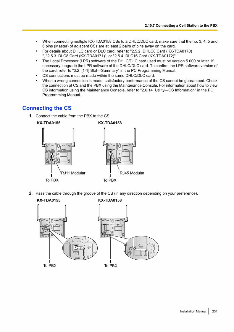
• When connecting multiple KX-TDA0158 CSs to a DHLC/DLC card, make sure that the no. 3, 4, 5 and6 pins (Master) of adjacent CSs are at least 2 pairs of pins away on the card.
• For details about DHLC card or DLC card, refer to "2.5.2 DHLC8 Card (KX-TDA0170)", "2.5.3 DLC8 Card (KX-TDA0171)", or "2.5.4 DLC16 Card (KX-TDA0172)".
• The Local Processor (LPR) software of the DHLC/DLC card used must be version 5.000 or later. Ifnecessary, upgrade the LPR software of the DHLC/DLC card. To confirm the LPR software version ofthe card, refer to "3.2 [1-1] Slot—Summary" in the PC Programming Manual.
• CS connections must be made within the same DHLC/DLC card.• When a wrong connection is made, satisfactory performance of the CS cannot be guaranteed. Check
the connection of CS and the PBX using the Maintenance Console. For information about how to viewCS information using the Maintenance Console, refer to "2.6.14 Utility—CS Information" in the PCProgramming Manual.
Connecting the CS1. Connect the cable from the PBX to the CS.
KX-TDA0155
RJ11 Modular
To PBX
KX-TDA0158
RJ45 Modular
To PBX
2. Pass the cable through the groove of the CS (in any direction depending on your preference).
KX-TDA0155
To PBX
KX-TDA0158
To PBX
Installation Manual 231
2.10.7 Connecting a Cell Station to the PBX
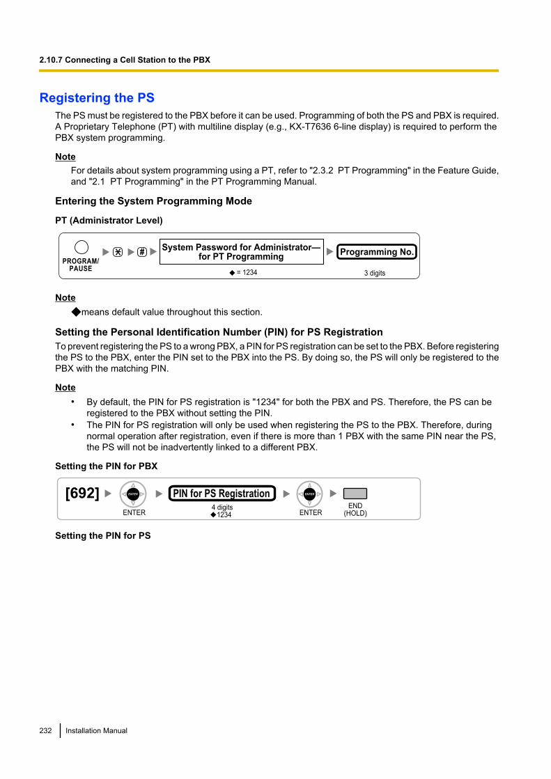
Registering the PSThe PS must be registered to the PBX before it can be used. Programming of both the PS and PBX is required.A Proprietary Telephone (PT) with multiline display (e.g., KX-T7636 6-line display) is required to perform thePBX system programming.
NoteFor details about system programming using a PT, refer to "2.3.2 PT Programming" in the Feature Guide,and "2.1 PT Programming" in the PT Programming Manual.
Entering the System Programming Mode
PT (Administrator Level)
#
= 1234
System Password for Administrator—for PT Programming
Programming No.
3 digits
PROGRAM/PAUSE
Notemeans default value throughout this section.
Setting the Personal Identification Number (PIN) for PS RegistrationTo prevent registering the PS to a wrong PBX, a PIN for PS registration can be set to the PBX. Before registeringthe PS to the PBX, enter the PIN set to the PBX into the PS. By doing so, the PS will only be registered to thePBX with the matching PIN.
Note• By default, the PIN for PS registration is "1234" for both the PBX and PS. Therefore, the PS can be
registered to the PBX without setting the PIN.• The PIN for PS registration will only be used when registering the PS to the PBX. Therefore, during
normal operation after registration, even if there is more than 1 PBX with the same PIN near the PS,the PS will not be inadvertently linked to a different PBX.
Setting the PIN for PBX
[692]4 digits
PIN for PS RegistrationEND
(HOLD)ENTER ENTER1234
Setting the PIN for PS
232 Installation Manual
2.10.7 Connecting a Cell Station to the PBX
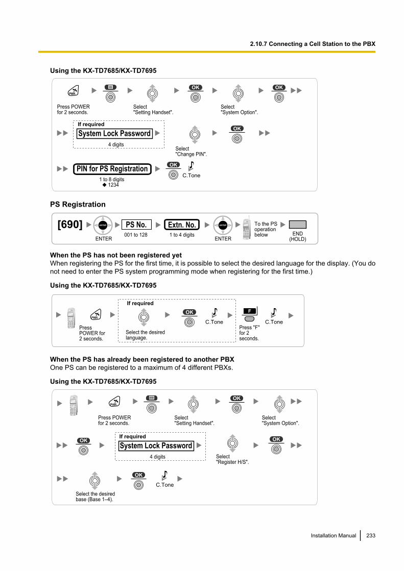
Using the KX-TD7685/KX-TD7695
Select "Change PIN".
1 to 8 digits1234
C.TonePIN for PS Registration
Press POWERfor 2 seconds.
Select "Setting Handset".
Select "System Option".
If required
4 digits
System Lock Password
PS Registration
[690]001 to 128
PS No.1 to 4 digits END
(HOLD)ENTER ENTER
To the PSoperationbelow
Extn. No.
When the PS has not been registered yetWhen registering the PS for the first time, it is possible to select the desired language for the display. (You donot need to enter the PS system programming mode when registering for the first time.)
Using the KX-TD7685/KX-TD7695
Press POWER for 2 seconds.
Select the desired language.
Press "F" for 2 seconds.
C.Tone C.Tone
If required
When the PS has already been registered to another PBXOne PS can be registered to a maximum of 4 different PBXs.
Using the KX-TD7685/KX-TD7695
Select the desiredbase (Base 1–4).
Select "Register H/S".
C.Tone
Press POWERfor 2 seconds.
Select "Setting Handset".
Select "System Option".
If required
4 digits
System Lock Password
Installation Manual 233
2.10.7 Connecting a Cell Station to the PBX

PS TerminationConfirm the following before cancelling the PS registration:• The PS is turned on.• The PS is within range.
[691]001 to 128
PS No.
ENTER ENTER
END(HOLD)
If "Rejected" or "Time out" is displayed
CLEAR YES
Press "YES".Press "CLEAR".
If "Rejected" or "Time out" is displayedThe registration information is still stored in the PS. You need to delete the registration information from thePS.
Using the KX-TD7685/KX-TD7695
Select the desiredbase (Base 1–4).
Select "Yes".
C.Tone
Select "Cancel Base".
Press POWERfor 2 seconds.
Select "Setting Handset".
Select "System Option".
If required
4 digits
System Lock Password
Testing the OperationWalk around the service area while having a conversation using a registered PS. If noise is frequent orconversations disconnect, relocate the CSs or install an additional CS.
234 Installation Manual
2.10.7 Connecting a Cell Station to the PBX

2.10.8 Wall MountingMounting the KX-TDA0155/KX-TDA0158
WARNING• Make sure that the wall that the unit will be attached to is strong enough to support the unit
(approx. 310 g). If not, it is necessary for the wall to be reinforced.• Only use the wall-mounting equipment (screws, washers, wall mounting plate) included with
the unit.• When driving the screws into the wall, be careful to avoid touching any metal laths, wire laths
or metal plates in the wall.• When this product is no longer in use, make sure to detach it from the wall.
CAUTION• Do not stretch or bend the cables. Also, do not allow anything to rest on the cables.• Use cables that are fire-resistant or fireproof.• The CS and the cables should never be placed near or over a radiator or other heat source.• Do not bundle cables that are connected to the CS with the AC power cords of machines located
nearby.• Make sure the cables are securely fastened to the wall.
1. Place the reference for wall mounting on the wall to mark the 2 screw positions.2. Install the 2 screws and washers (included) into the wall.
Note• Make sure that the screw heads are at the same distance from the wall.• Install the screws perpendicular to the wall.
3. Insert the upper and lower tabs of the wall mounting plate into the designated openings in the base unit.
KX-TDA0155
Tabs
Wall Mounting Plate
(PSKL1032Y4)
KX-TDA0158
Tabs
Wall Mounting Plate
(PSKL1032Y4)
Installation Manual 235
2.10.8 Wall Mounting
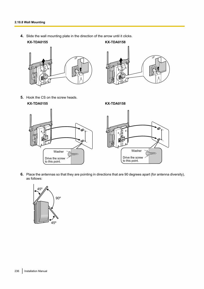
4. Slide the wall mounting plate in the direction of the arrow until it clicks.
KX-TDA0155 KX-TDA0158
5. Hook the CS on the screw heads.
KX-TDA0155
Washer
Drive the screw to this point.
KX-TDA0158
Drive the screw to this point.
Washer
6. Place the antennas so that they are pointing in directions that are 90 degrees apart (for antenna diversity),as follows:
45º
45º
90º
236 Installation Manual
2.10.8 Wall Mounting
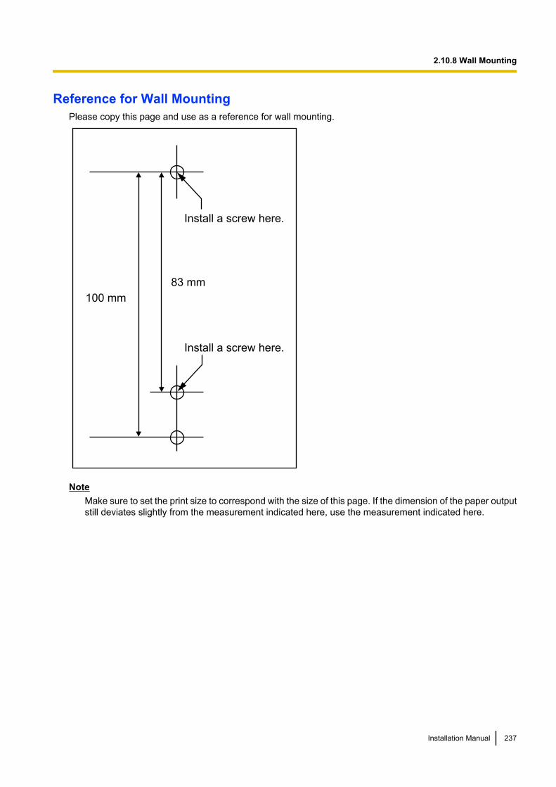
Reference for Wall MountingPlease copy this page and use as a reference for wall mounting.
Install a screw here.
Install a screw here.
83 mm
100 mm
NoteMake sure to set the print size to correspond with the size of this page. If the dimension of the paper outputstill deviates slightly from the measurement indicated here, use the measurement indicated here.
Installation Manual 237
2.10.8 Wall Mounting
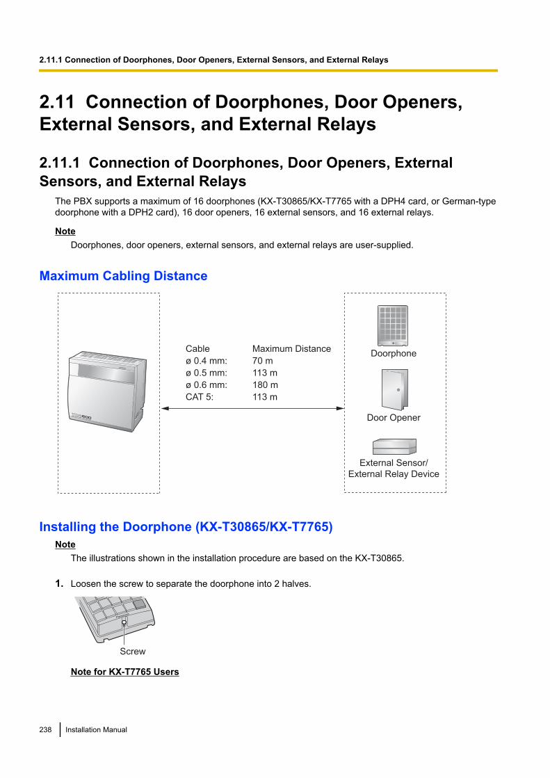
2.11 Connection of Doorphones, Door Openers,External Sensors, and External Relays
2.11.1 Connection of Doorphones, Door Openers, ExternalSensors, and External Relays
The PBX supports a maximum of 16 doorphones (KX-T30865/KX-T7765 with a DPH4 card, or German-typedoorphone with a DPH2 card), 16 door openers, 16 external sensors, and 16 external relays.
NoteDoorphones, door openers, external sensors, and external relays are user-supplied.
Maximum Cabling Distance
Cable Maximum Distance
ø 0.4 mm: 70 m
ø 0.5 mm: 113 m
ø 0.6 mm: 180 m
CAT 5: 113 m
Doorphone
Door Opener
External Sensor/
External Relay Device
Installing the Doorphone (KX-T30865/KX-T7765)Note
The illustrations shown in the installation procedure are based on the KX-T30865.
1. Loosen the screw to separate the doorphone into 2 halves.
Panasonic
Screw
Note for KX-T7765 Users
238 Installation Manual
2.11.1 Connection of Doorphones, Door Openers, External Sensors, and External Relays
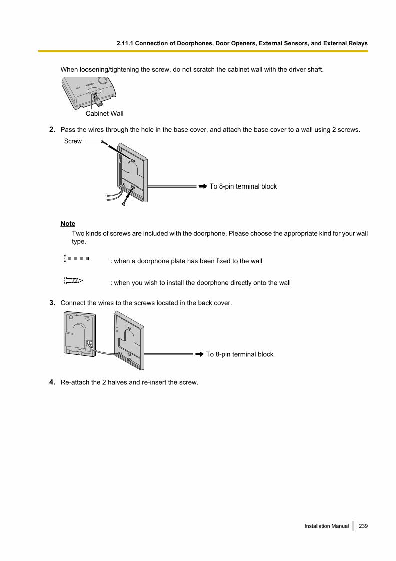
When loosening/tightening the screw, do not scratch the cabinet wall with the driver shaft.
Cabinet Wall
2. Pass the wires through the hole in the base cover, and attach the base cover to a wall using 2 screws.
Screw
To 8-pin terminal block
NoteTwo kinds of screws are included with the doorphone. Please choose the appropriate kind for your walltype.
: when a doorphone plate has been fixed to the wall
: when you wish to install the doorphone directly onto the wall
3. Connect the wires to the screws located in the back cover.
To 8-pin terminal block
4. Re-attach the 2 halves and re-insert the screw.
Installation Manual 239
2.11.1 Connection of Doorphones, Door Openers, External Sensors, and External Relays
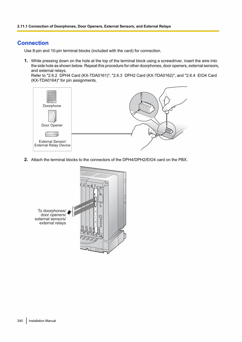
ConnectionUse 8-pin and 10-pin terminal blocks (included with the card) for connection.
1. While pressing down on the hole at the top of the terminal block using a screwdriver, insert the wire intothe side hole as shown below. Repeat this procedure for other doorphones, door openers, external sensors,and external relays.Refer to "2.6.2 DPH4 Card (KX-TDA0161)", "2.6.3 DPH2 Card (KX-TDA0162)", and "2.6.4 EIO4 Card(KX-TDA0164)" for pin assignments.
Doorphone
Door Opener
External Sensor/External Relay Device
2. Attach the terminal blocks to the connectors of the DPH4/DPH2/EIO4 card on the PBX.
To doorphones/door openers/
external sensors/external relays
240 Installation Manual
2.11.1 Connection of Doorphones, Door Openers, External Sensors, and External Relays
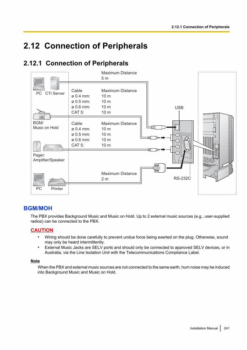
2.12 Connection of Peripherals
2.12.1 Connection of Peripherals
BGM/
Music on Hold
Pager:
Amplifier/Speaker
PC Printer
PCCable Maximum Distance
ø 0.4 mm: 10 m
ø 0.5 mm: 10 m
ø 0.6 mm: 10 m
CAT 5: 10 m
Cable Maximum Distance
ø 0.4 mm: 10 m
ø 0.5 mm: 10 m
ø 0.6 mm: 10 m
CAT 5: 10 m
Maximum Distance
5 m
Maximum Distance
2 m
USB
RS-232C
CTI Server
BGM/MOHThe PBX provides Background Music and Music on Hold. Up to 2 external music sources (e.g., user-suppliedradios) can be connected to the PBX.
CAUTION• Wiring should be done carefully to prevent undue force being exerted on the plug. Otherwise, sound
may only be heard intermittently.• External Music Jacks are SELV ports and should only be connected to approved SELV devices, or in
Australia, via the Line Isolation Unit with the Telecommunications Compliance Label.
NoteWhen the PBX and external music sources are not connected to the same earth, hum noise may be inducedinto Background Music and Music on Hold.
Installation Manual 241
2.12.1 Connection of Peripherals
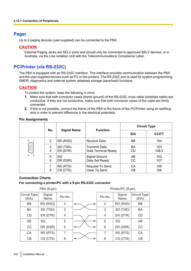
PagerUp to 2 paging devices (user-supplied) can be connected to the PBX.
CAUTIONExternal Paging Jacks are SELV ports and should only be connected to approved SELV devices, or inAustralia, via the Line Isolation Unit with the Telecommunications Compliance Label.
PC/Printer (via RS-232C)The PBX is equipped with an RS-232C interface. This interface provides communication between the PBXand the user-supplied devices such as PC or line printers. The RS-232C port is used for system programming,SMDR, diagnostics and external system database storage (save/load) functions.
CAUTIONTo protect the system, keep the following in mind:1. Make sure that both connector cases (frame ground) of the RS-232C cross cable (shielded cable) are
conductive. If they are not conductive, make sure that both connector cases of the cable are firmlyconnected.
2. If this is not possible, connect the frame of the PBX to the frame of the PC/Printer using an earthingwire in order to prevent difference in the electrical potentials.
Pin Assignments
No. Signal Name FunctionCircuit Type
EIA CCITT
9 5
6 1 2 RD (RXD) Receive Data BB 104
34
SD (TXD)ER (DTR)
Transmit DataData Terminal Ready
BACD
103108.2
56
SGDR (DSR)
Signal GroundData Set Ready
ABCC
102107
78
RS (RTS)CS (CTS)
Request To SendClear To Send
CACB
105106
Connection ChartsFor connecting a printer/PC with a 9-pin RS-232C connector
PBX (9-pin) Printer/PC (9-pin)
Circuit Type
(EIA)
Signal
NamePin No. Pin No.
Signal
Name
Circuit Type
(EIA)
BB RD (RXD) 2
BA SD (TXD) 3
CD ER (DTR) 4
AB SG 5
CC DR (DSR) 6
CA RS (RTS) 7
CB CS (CTS) 8
2 RD (RXD) BB
3 SD (TXD) BA
4 ER (DTR) CD
5 SG AB
6 DR (DSR) CC
7 RS (RTS) CA
8 CS (CTS) CB
242 Installation Manual
2.12.1 Connection of Peripherals
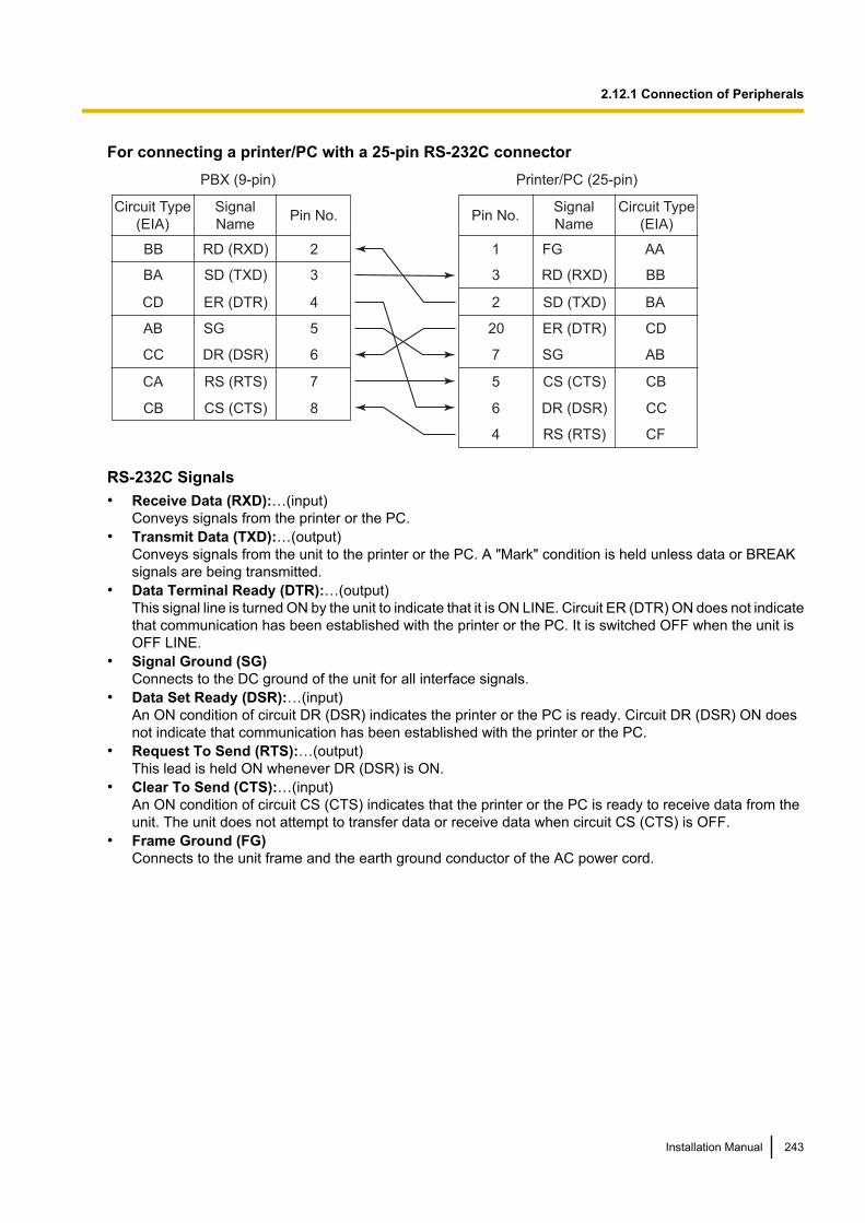
For connecting a printer/PC with a 25-pin RS-232C connectorPBX (9-pin) Printer/PC (25-pin)
Circuit Type
(EIA)
Signal
NamePin No.
Signal
Name
Circuit Type
(EIA)
BB RD (RXD) 2
BA SD (TXD) 3
CD ER (DTR) 4
AB SG 5
CC DR (DSR) 6
CA RS (RTS) 7
CB CS (CTS) 8
1 FG AA
3 RD (RXD) BB
2 SD (TXD) BA
20 ER (DTR) CD
7 SG AB
5 CS (CTS) CB
6 DR (DSR) CC
CF4 RS (RTS)
Pin No.
RS-232C Signals• Receive Data (RXD):…(input)
Conveys signals from the printer or the PC.• Transmit Data (TXD):…(output)
Conveys signals from the unit to the printer or the PC. A "Mark" condition is held unless data or BREAKsignals are being transmitted.
• Data Terminal Ready (DTR):…(output)This signal line is turned ON by the unit to indicate that it is ON LINE. Circuit ER (DTR) ON does not indicatethat communication has been established with the printer or the PC. It is switched OFF when the unit isOFF LINE.
• Signal Ground (SG)Connects to the DC ground of the unit for all interface signals.
• Data Set Ready (DSR):…(input)An ON condition of circuit DR (DSR) indicates the printer or the PC is ready. Circuit DR (DSR) ON doesnot indicate that communication has been established with the printer or the PC.
• Request To Send (RTS):…(output)This lead is held ON whenever DR (DSR) is ON.
• Clear To Send (CTS):…(input)An ON condition of circuit CS (CTS) indicates that the printer or the PC is ready to receive data from theunit. The unit does not attempt to transfer data or receive data when circuit CS (CTS) is OFF.
• Frame Ground (FG)Connects to the unit frame and the earth ground conductor of the AC power cord.
Installation Manual 243
2.12.1 Connection of Peripherals

PC/CTI Server (via USB version 2.0)The PBX is equipped with a USB interface. This interface provides communication between the PBX and aPC or a CTI server.The PC is used for system programming, diagnostics and external system database storage (save/load)functions.The CTI server is used for connecting PCs on a LAN to provide third party call control CTI. The CTI connectionuses the CSTA Phase 3 or TAPI 2.1 protocol.
NoteThe operating system of the PC or CTI server required for third party call control depends on your CTIapplication software. For details, refer to the manual for your CTI application software.
CAUTIONTo protect the system, keep the following in mind:1. Make sure that both connector cases (frame ground) of the USB cable are conductive. If they are not
conductive, make sure that both connector cases of the cable are firmly connected.2. If this is not possible, connect the frame of the PBX to the frame of the PC/CTI server using an earthing
wire in order to prevent difference in the electrical potentials.
Pin Assignments
No. Signal Name
2
1
3
4
1 VBUS
2 USB D-
3 USB D+
4 GND
244 Installation Manual
2.12.1 Connection of Peripherals
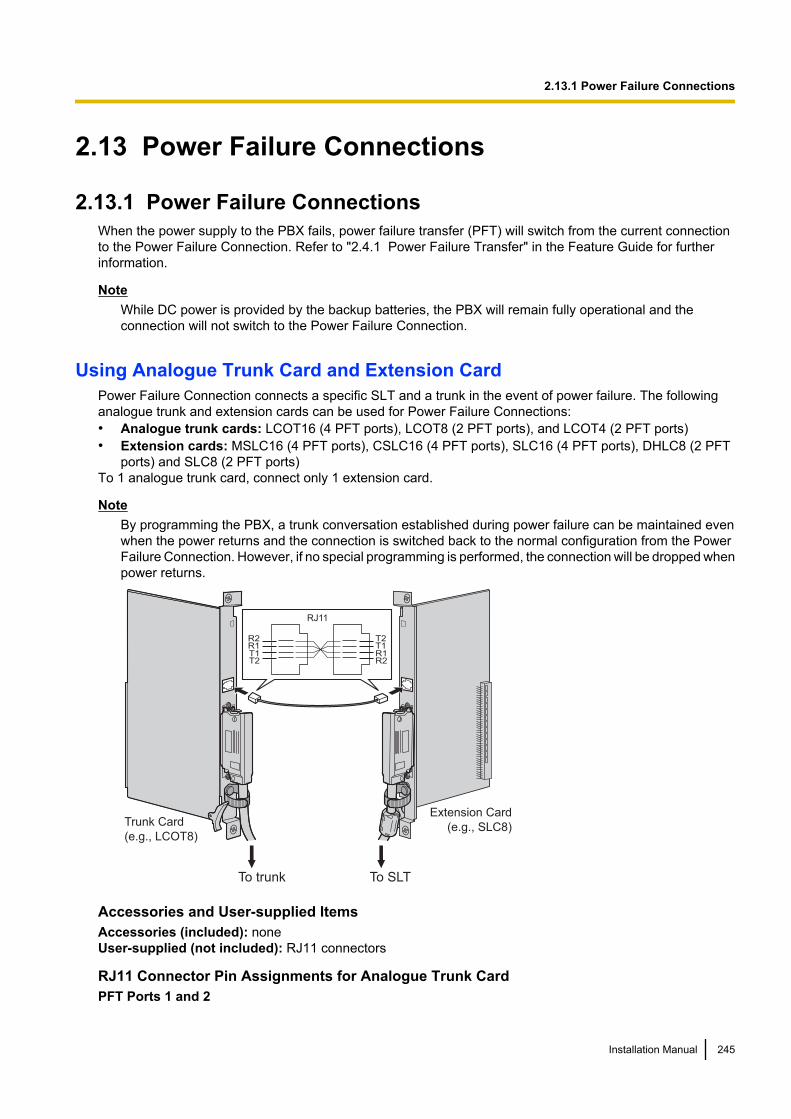
2.13 Power Failure Connections
2.13.1 Power Failure ConnectionsWhen the power supply to the PBX fails, power failure transfer (PFT) will switch from the current connectionto the Power Failure Connection. Refer to "2.4.1 Power Failure Transfer" in the Feature Guide for furtherinformation.
NoteWhile DC power is provided by the backup batteries, the PBX will remain fully operational and theconnection will not switch to the Power Failure Connection.
Using Analogue Trunk Card and Extension CardPower Failure Connection connects a specific SLT and a trunk in the event of power failure. The followinganalogue trunk and extension cards can be used for Power Failure Connections:• Analogue trunk cards: LCOT16 (4 PFT ports), LCOT8 (2 PFT ports), and LCOT4 (2 PFT ports)• Extension cards: MSLC16 (4 PFT ports), CSLC16 (4 PFT ports), SLC16 (4 PFT ports), DHLC8 (2 PFT
ports) and SLC8 (2 PFT ports)To 1 analogue trunk card, connect only 1 extension card.
NoteBy programming the PBX, a trunk conversation established during power failure can be maintained evenwhen the power returns and the connection is switched back to the normal configuration from the PowerFailure Connection. However, if no special programming is performed, the connection will be dropped whenpower returns.
Trunk Card
(e.g., LCOT8)
Extension Card
(e.g., SLC8)
R2R1T1T2
T2T1R1R2
RJ11
To trunk To SLT
Accessories and User-supplied ItemsAccessories (included): noneUser-supplied (not included): RJ11 connectors
RJ11 Connector Pin Assignments for Analogue Trunk CardPFT Ports 1 and 2
Installation Manual 245
2.13.1 Power Failure Connections
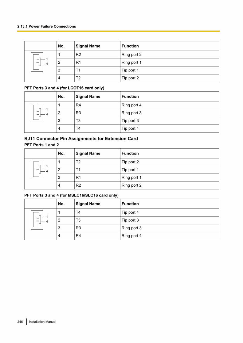
No. Signal Name Function
1
4
1 R2 Ring port 2
2 R1 Ring port 1
3 T1 Tip port 1
4 T2 Tip port 2
PFT Ports 3 and 4 (for LCOT16 card only)
No. Signal Name Function
1
4
1 R4 Ring port 4
2 R3 Ring port 3
3 T3 Tip port 3
4 T4 Tip port 4
RJ11 Connector Pin Assignments for Extension CardPFT Ports 1 and 2
No. Signal Name Function
1
4
1 T2 Tip port 2
2 T1 Tip port 1
3 R1 Ring port 1
4 R2 Ring port 2
PFT Ports 3 and 4 (for MSLC16/SLC16 card only)
No. Signal Name Function
1
4
1 T4 Tip port 4
2 T3 Tip port 3
3 R3 Ring port 3
4 R4 Ring port 4
246 Installation Manual
2.13.1 Power Failure Connections
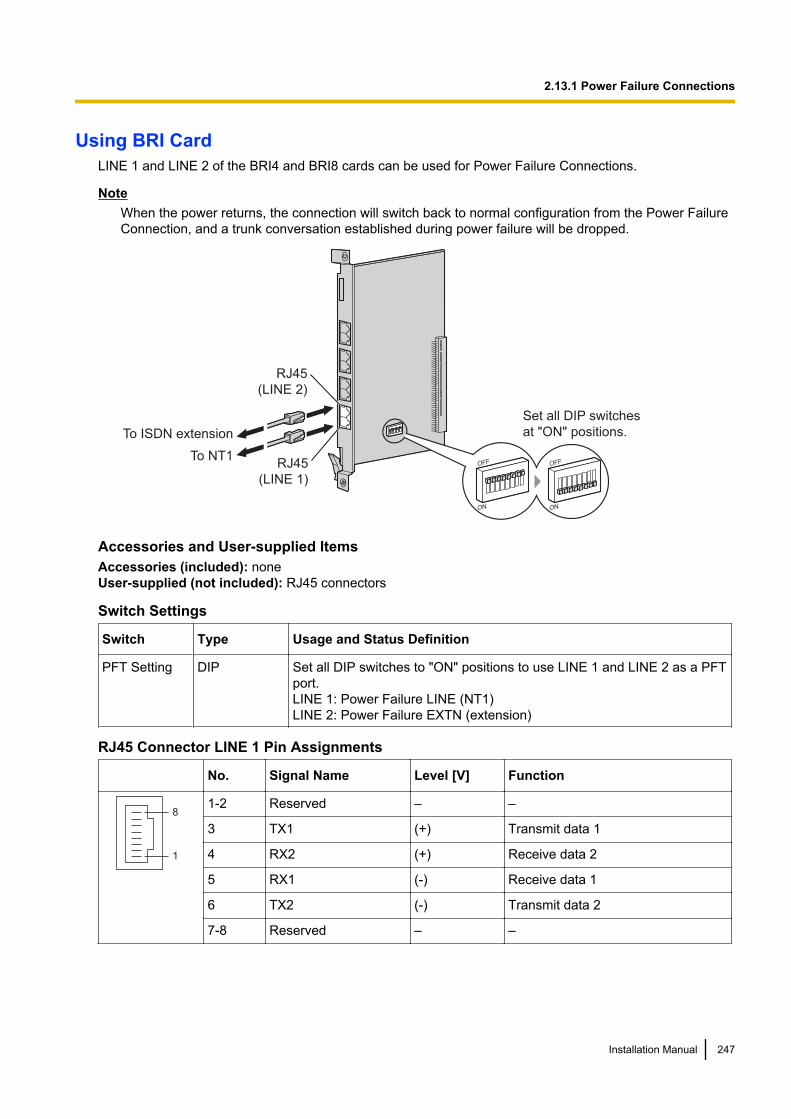
Using BRI CardLINE 1 and LINE 2 of the BRI4 and BRI8 cards can be used for Power Failure Connections.
NoteWhen the power returns, the connection will switch back to normal configuration from the Power FailureConnection, and a trunk conversation established during power failure will be dropped.
RJ45
(LINE 2)
RJ45
(LINE 1)
To NT1OFF
ON
OFF
ON
To ISDN extension
Set all DIP switches
at "ON" positions.
Accessories and User-supplied ItemsAccessories (included): noneUser-supplied (not included): RJ45 connectors
Switch Settings
Switch Type Usage and Status Definition
PFT Setting DIP Set all DIP switches to "ON" positions to use LINE 1 and LINE 2 as a PFTport.LINE 1: Power Failure LINE (NT1)LINE 2: Power Failure EXTN (extension)
RJ45 Connector LINE 1 Pin Assignments
No. Signal Name Level [V] Function
8
1
1-2 Reserved – –
3 TX1 (+) Transmit data 1
4 RX2 (+) Receive data 2
5 RX1 (-) Receive data 1
6 TX2 (-) Transmit data 2
7-8 Reserved – –
Installation Manual 247
2.13.1 Power Failure Connections
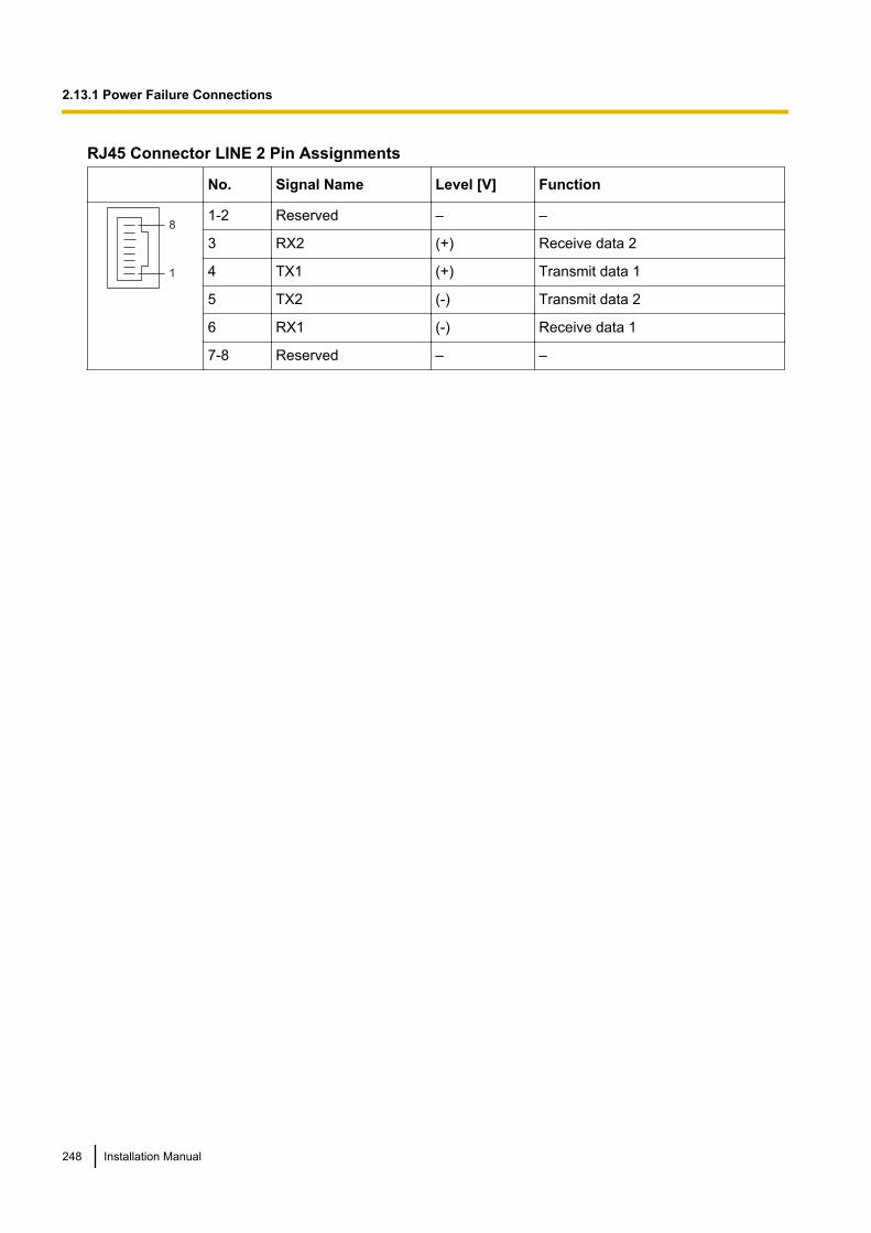
RJ45 Connector LINE 2 Pin Assignments
No. Signal Name Level [V] Function
8
1
1-2 Reserved – –
3 RX2 (+) Receive data 2
4 TX1 (+) Transmit data 1
5 TX2 (-) Transmit data 2
6 RX1 (-) Receive data 1
7-8 Reserved – –
248 Installation Manual
2.13.1 Power Failure Connections
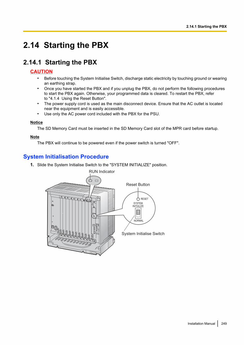
2.14 Starting the PBX
2.14.1 Starting the PBXCAUTION
• Before touching the System Initialise Switch, discharge static electricity by touching ground or wearingan earthing strap.
• Once you have started the PBX and if you unplug the PBX, do not perform the following proceduresto start the PBX again. Otherwise, your programmed data is cleared. To restart the PBX, referto "4.1.4 Using the Reset Button".
• The power supply cord is used as the main disconnect device. Ensure that the AC outlet is locatednear the equipment and is easily accessible.
• Use only the AC power cord included with the PBX for the PSU.
NoticeThe SD Memory Card must be inserted in the SD Memory Card slot of the MPR card before startup.
NoteThe PBX will continue to be powered even if the power switch is turned "OFF".
System Initialisation Procedure1. Slide the System Initialise Switch to the "SYSTEM INITIALIZE" position.
System Initialise Switch
Reset Button
SYSTEMINITIALIZE
RESET
NORMAL
RUN Indicator
Installation Manual 249
2.14.1 Starting the PBX

2. Plug the AC power cord into the PBX and an AC outlet, and turn on the PBX. The RUN indicator will flash.
NoteFor safety reasons, do not stretch, bend, or pinch the AC power cord.
To AC Outlet
3. While the RUN indicator is flashing, slide the System Initialise Switch back to the "NORMAL" position.Depending on the configuration, initialisation takes about 1 min to 3 min. If successfully executed, theRUN indicator will stop flashing and stay lit.
All data will be cleared, and the PBX as well as all optional service cards (except for the IP-GW card) will beinitialised to the default values. The DPTs should show the time as 01:00.The data of the IP-GW card will not be initialised.
LED IndicationsIndication Colour Description
RUN Green PBX status indication• OFF: Power Off (includes normal reset)• ON: Power On and running (on-line)• Flashing (60 times per minute): Starting up• Flashing (120 times per minute): Starting up or resetting with:
• the System Initialise Switch in "SYSTEM INITIALIZE" position• the SD Memory Card not inserted
ALARM Red Alarm indication• OFF: Normal• ON: Alarm (CPU stop, alarm for each optional service card installed in
the Basic Shelf)• Flashing: Alarm (MPR file error in restarting)
Confirming the Trunk ConnectionAfter initialisation, programme the PBX and connect trunks to the PBX.
To confirm that the trunks are successfully connected, dial [ ] [3] [7] + trunk number (3 digits) on a PT, orpress the PT's S-CO button. You will hear a dial tone if the trunk is available and connected.
250 Installation Manual
2.14.1 Starting the PBX

Section 3
Guide for the Maintenance Console
Explains the installation procedure, structure, and basicinformation of the Maintenance Console.
Installation Manual 251
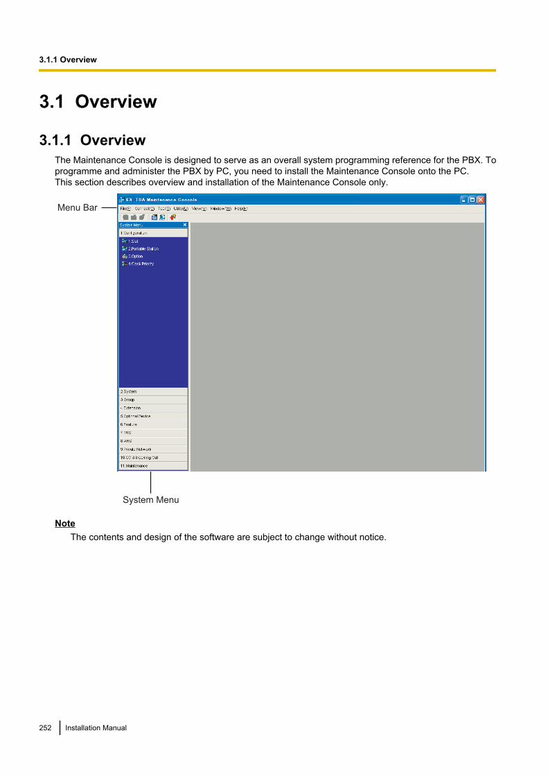
3.1 Overview
3.1.1 OverviewThe Maintenance Console is designed to serve as an overall system programming reference for the PBX. Toprogramme and administer the PBX by PC, you need to install the Maintenance Console onto the PC.This section describes overview and installation of the Maintenance Console only.
System Menu
Menu Bar
NoteThe contents and design of the software are subject to change without notice.
252 Installation Manual
3.1.1 Overview

3.2 PC Connection
3.2.1 PC ConnectionSerial Interface Connection
PC
USB Port
To USB Port
To COM Port
RS-232C Port
PC
CAUTIONTo protect the system, keep the following in mind:1. Make sure that both connector cases (frame ground) of the RS-232C cross cable (shielded cable)/USB
cable are conductive. If they are not conductive, make sure that both connector cases of the cable arefirmly connected.
2. If this is not possible, connect the frame of the PBX to the frame of the PC using an earthing wire inorder to prevent difference in the electrical potentials.
NoteFor pin assignments and maximum cabling distance, refer to "2.12.1 Connection of Peripherals".
LAN Connection via CTI-LINK Card
PC
Switching Hub
To network port
RJ45
Installation Manual 253
3.2.1 PC Connection
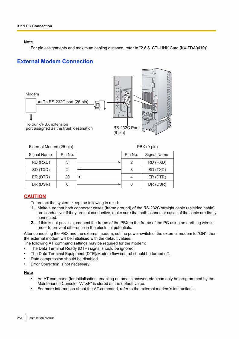
NoteFor pin assignments and maximum cabling distance, refer to "2.6.8 CTI-LINK Card (KX-TDA0410)".
External Modem Connection
To RS-232C port (25-pin)
RS-232C Port
(9-pin)
To trunk/PBX extensionport assigned as the trunk destination
Modem
External Modem (25-pin) PBX (9-pin)
3
2
20
6
RD (RXD)
SD (TXD)
ER (DTR)
DR (DSR)
2 RD (RXD)
3 SD (TXD)
4 ER (DTR)
6 DR (DSR)
Signal Name Pin No. Pin No. Signal Name
CAUTIONTo protect the system, keep the following in mind:1. Make sure that both connector cases (frame ground) of the RS-232C straight cable (shielded cable)
are conductive. If they are not conductive, make sure that both connector cases of the cable are firmlyconnected.
2. If this is not possible, connect the frame of the PBX to the frame of the PC using an earthing wire inorder to prevent difference in the electrical potentials.
After connecting the PBX and the external modem, set the power switch of the external modem to "ON", thenthe external modem will be initialised with the default values.The following AT command settings may be required for the modem:• The Data Terminal Ready (DTR) signal should be ignored.• The Data Terminal Equipment (DTE)/Modem flow control should be turned off.• Data compression should be disabled.• Error Correction is not necessary.
Note• An AT command (for initialisation, enabling automatic answer, etc.) can only be programmed by the
Maintenance Console. "AT&F" is stored as the default value.• For more information about the AT command, refer to the external modem's instructions.
254 Installation Manual
3.2.1 PC Connection
3.3 Installation of the Maintenance Console
3.3.1 Installing and Starting the Maintenance ConsoleSystem Requirements
Required Operating System• Microsoft® Windows® XP or Windows Vista® Business
Minimum Hardware Requirements• HDD: 100 MB of available hard disk space
Recommended Display Settings• Screen resolution: XGA (1024 ´ 768)• DPI setting: Normal size (96 DPI)
Password SecurityCAUTION
To the Administrator or Installer regarding the system password1. Please provide all system passwords to the customer.2. To avoid unauthorised access and possible abuse of the PBX, keep the passwords secret, and inform
the customer of the importance of the passwords, and the possible dangers if they become known toothers.
3. The PBX has default passwords preset. For security, change these passwords the first time that youprogramme the PBX.
4. Change the passwords periodically.5. It is strongly recommended that passwords of 10 numbers or characters be used for maximum
protection against unauthorised access. For a list of numbers and characters that can be used in systempasswords, refer to "1.1.2 Entering Characters" in the PC Programming Manual.
Installation Manual 255
3.3.1 Installing and Starting the Maintenance Console

Installing the Maintenance ConsoleNote
• Make sure to install and use the latest version of the Maintenance Console.• To install or uninstall the software on a PC running Windows XP Professional, you must be logged in
as a user in either the "Administrators" or "Power Users" group.• To install or uninstall the software on a PC running Windows Vista Business, you must be logged in
as a user in the "Administrators" group.• To connect the PC to the PBX via USB, the KX-TDA USB driver must be installed. Follow the
instructions of the wizard to install the KX-TDA USB driver. When the PBX is first connected to the PCvia USB, you may be asked to select the appropriate USB driver. Browse for and select the KX-TDAUSB driver that was installed previously.
1. Copy the setup file of the Maintenance Console to your PC.2. Double-click the setup file to run the installer.3. Follow the on-screen instructions provided by the installation wizard.
Starting the Maintenance Console and Assigning the Basic Items (QuickSetup)
When you start the Maintenance Console with the Installer Level Programmer Code and connect to the PBXfor the first time after initialisation (with the factory default setting), Quick Setup will launch automatically. DuringQuick Setup, you will set up the basic items. For details about the basic items, refer to "2.3.4 Quick Setup" inthe Feature Guide.
1. Connect the PC to the PBX with a USB cable.
2. Start the Maintenance Console from the Start menu.
3. "Information before programming" appears.a. Carefully read this important additional information,
which includes updates to this and other manuals.b. Click OK to close this window.
4. a. Enter the Installer Level Programmer Code (default:INSTALLER).The Programmer Code authorises differentprogramming levels, and the Quick Setup is onlyavailable when you start the Maintenance Console withthe Installer Level Programmer Code.
NoteThere are 2 other Programmer Codes with limitedauthorisation: Administrator Level (default:ADMIN), and User Level (default: USER).
b. Click OK.
5. Click Connect.
256 Installation Manual
3.3.1 Installing and Starting the Maintenance Console

6. a. Select KX-TDA100/200 from PBX Model.b. Select the USB tab.c. Enter the system password for installer (default: 1234).d. Click Connect.
NoteTo connect to the PBX via USB, the KX-TDA USB drivermust be installed on the PC, as explained abovein "Installing the Maintenance Console".
7. When country/area data do not match:a. Click OK to replace the country/area data of the PBX.
Replacement may take several minutes to complete.b. Follow the procedure described in "2.14.1 Starting the
PBX" and restart the PBX.c. Repeat step 5 to reconnect the Maintenance Console
to the PBX.
8. Follow the instructions of the Quick Setup wizard and assignthe basic items (Quick Setup).
The system menu appears. You may now beginprogramming the PBX.
Note1. During a long programming session, it is highly recommended that you periodically save the system
data to the SD Memory Card. If the PBX undergoes a sudden power failure or if the system is reset forsome reason, all the system data in RAM will be lost. However, if system data has been saved to theSD Memory Card, it can be easily restored.To save the system data to the SD Memory Card, (1) click the "SD Memory Backup" icon beforeresetting the PBX or turning off the power, or (2) exit the Maintenance Console so that the PBXautomatically saves the system data.
2. The PC will not perform any shutdown operation, or enter the power-saving system standby modewhile the Maintenance Console is connected to the PBX. To perform either of the operations above,first close the connection to the PBX.
Installation Manual 257
3.3.1 Installing and Starting the Maintenance Console
CAUTIONDo not remove the SD Memory Card while power is supplied to the PBX. Doing so may cause the PBX tofail to start when you try to restart the system.
258 Installation Manual
3.3.1 Installing and Starting the Maintenance Console
Section 4
Troubleshooting
This section provides information on the PBX andtelephone troubleshooting.
Installation Manual 259
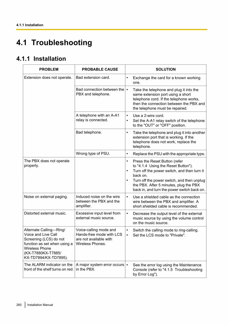
4.1 Troubleshooting
4.1.1 InstallationPROBLEM PROBABLE CAUSE SOLUTION
Extension does not operate. Bad extension card. • Exchange the card for a known workingone.
Bad connection between thePBX and telephone.
• Take the telephone and plug it into thesame extension port using a shorttelephone cord. If the telephone works,then the connection between the PBX andthe telephone must be repaired.
A telephone with an A-A1relay is connected.
• Use a 2-wire cord.• Set the A-A1 relay switch of the telephone
to the "OUT" or "OFF" position.
Bad telephone. • Take the telephone and plug it into anotherextension port that is working. If thetelephone does not work, replace thetelephone.
Wrong type of PSU. • Replace the PSU with the appropriate type.
The PBX does not operateproperly.
• Press the Reset Button (referto "4.1.4 Using the Reset Button").
• Turn off the power switch, and then turn itback on.
• Turn off the power switch, and then unplugthe PBX. After 5 minutes, plug the PBXback in, and turn the power switch back on.
Noise on external paging. Induced noise on the wirebetween the PBX and theamplifier.
• Use a shielded cable as the connectionwire between the PBX and amplifier. Ashort shielded cable is recommended.
Distorted external music. Excessive input level fromexternal music source.
• Decrease the output level of the externalmusic source by using the volume controlon the music source.
Alternate Calling—Ring/Voice and Live CallScreening (LCS) do notfunction as set when using aWireless Phone(KX-T7880KX-T7885/KX-TD7894/KX-TD7895).
Voice-calling mode andHands-free mode with LCSare not available withWireless Phones.
• Switch the calling mode to ring-calling.• Set the LCS mode to "Private".
The ALARM indicator on thefront of the shelf turns on red.
A major system error occursin the PBX.
• See the error log using the MaintenanceConsole (refer to "4.1.5 Troubleshootingby Error Log").
260 Installation Manual
4.1.1 Installation
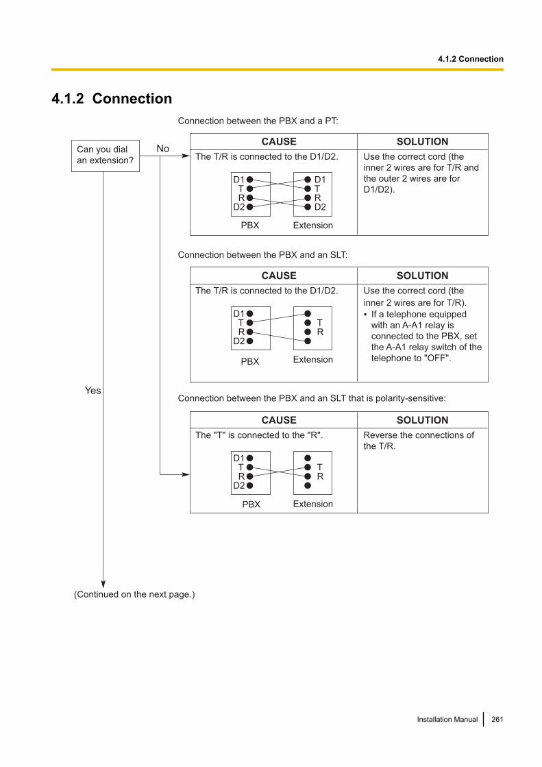
4.1.2 ConnectionConnection between the PBX and a PT:
Connection between the PBX and an SLT:
Connection between the PBX and an SLT that is polarity-sensitive:
CAUSE
The T/R is connected to the D1/D2.
SOLUTION
Use the correct cord (the
inner 2 wires are for T/R and
the outer 2 wires are for
D1/D2).D1TR
D2
D1 TR D2
PBX
PBX
PBX
Extension
CAUSE
The T/R is connected to the D1/D2.
SOLUTION
Use the correct cord (the
inner 2 wires are for T/R).
•D1TR
D2
TR
Extension
CAUSE
The "T" is connected to the "R".
SOLUTION
Reverse the connections of
the T/R.
D1TR
D2
TR
Extension
Can you dial
an extension?
(Continued on the next page.)
No
Yes
If a telephone equipped
with an A-A1 relay is
connected to the PBX, set
the A-A1 relay switch of the
telephone to "OFF".
Installation Manual 261
4.1.2 Connection
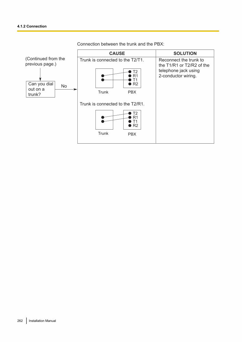
Connection between the trunk and the PBX:
CAUSE
Trunk is connected to the T2/T1.
Trunk is connected to the T2/R1.
SOLUTION
Reconnect the trunk to
the T1/R1 or T2/R2 of the
telephone jack using
2-conductor wiring.T2 R1T1R2
Trunk PBX
PBXTrunk
T2 R1T1R2
(Continued from the
previous page.)
Can you dial
out on a
trunk?
No
262 Installation Manual
4.1.2 Connection
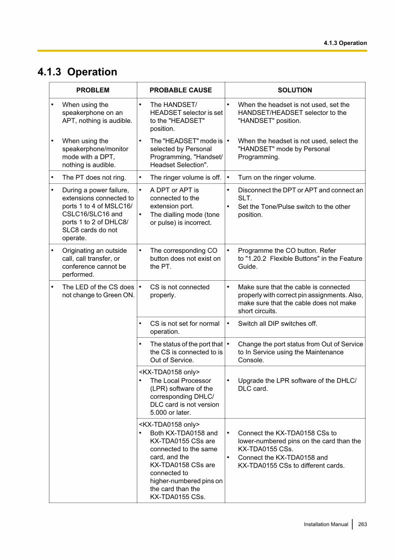
4.1.3 OperationPROBLEM PROBABLE CAUSE SOLUTION
• When using thespeakerphone on anAPT, nothing is audible.
• The HANDSET/HEADSET selector is setto the "HEADSET"position.
• When the headset is not used, set theHANDSET/HEADSET selector to the"HANDSET" position.
• When using thespeakerphone/monitormode with a DPT,nothing is audible.
• The "HEADSET" mode isselected by PersonalProgramming, "Handset/Headset Selection".
• When the headset is not used, select the"HANDSET" mode by PersonalProgramming.
• The PT does not ring. • The ringer volume is off. • Turn on the ringer volume.
• During a power failure,extensions connected toports 1 to 4 of MSLC16/CSLC16/SLC16 andports 1 to 2 of DHLC8/SLC8 cards do notoperate.
• A DPT or APT isconnected to theextension port.
• The dialling mode (toneor pulse) is incorrect.
• Disconnect the DPT or APT and connect anSLT.
• Set the Tone/Pulse switch to the otherposition.
• Originating an outsidecall, call transfer, orconference cannot beperformed.
• The corresponding CObutton does not exist onthe PT.
• Programme the CO button. Referto "1.20.2 Flexible Buttons" in the FeatureGuide.
• The LED of the CS doesnot change to Green ON.
• CS is not connectedproperly.
• Make sure that the cable is connectedproperly with correct pin assignments. Also,make sure that the cable does not makeshort circuits.
• CS is not set for normaloperation.
• Switch all DIP switches off.
• The status of the port thatthe CS is connected to isOut of Service.
• Change the port status from Out of Serviceto In Service using the MaintenanceConsole.
<KX-TDA0158 only>• The Local Processor
(LPR) software of thecorresponding DHLC/DLC card is not version5.000 or later.
• Upgrade the LPR software of the DHLC/DLC card.
<KX-TDA0158 only>• Both KX-TDA0158 and
KX-TDA0155 CSs areconnected to the samecard, and theKX-TDA0158 CSs areconnected tohigher-numbered pins onthe card than theKX-TDA0155 CSs.
• Connect the KX-TDA0158 CSs tolower-numbered pins on the card than theKX-TDA0155 CSs.
• Connect the KX-TDA0158 andKX-TDA0155 CSs to different cards.
Installation Manual 263
4.1.3 Operation
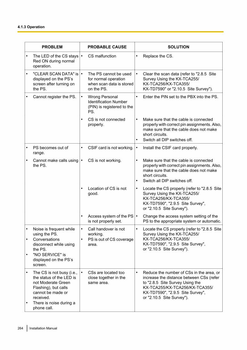
PROBLEM PROBABLE CAUSE SOLUTION
• The LED of the CS staysRed ON during normaloperation.
• CS malfunction • Replace the CS.
• "CLEAR SCAN DATA" isdisplayed on the PS’sscreen after turning onthe PS.
• The PS cannot be usedfor normal operationwhen scan data is storedon the PS.
• Clear the scan data (refer to "2.8.5 SiteSurvey Using the KX-TCA255/KX-TCA256/KX-TCA355/KX-TD7590" or "2.10.5 Site Survey").
• Cannot register the PS. • Wrong PersonalIdentification Number(PIN) is registered to thePS.
• Enter the PIN set to the PBX into the PS.
• CS is not connectedproperly.
• Make sure that the cable is connectedproperly with correct pin assignments. Also,make sure that the cable does not makeshort circuits.
• Switch all DIP switches off.
• PS becomes out ofrange.
• CSIF card is not working. • Install the CSIF card properly.
• Cannot make calls usingthe PS.
• CS is not working. • Make sure that the cable is connectedproperly with correct pin assignments. Also,make sure that the cable does not makeshort circuits.
• Switch all DIP switches off.
• Location of CS is notgood.
• Locate the CS properly (refer to "2.8.5 SiteSurvey Using the KX-TCA255/KX-TCA256/KX-TCA355/KX-TD7590", "2.9.5 Site Survey",or "2.10.5 Site Survey").
• Access system of the PSis not properly set.
• Change the access system setting of thePS to the appropriate system or automatic.
• Noise is frequent whileusing the PS.
• Conversationsdisconnect while usingthe PS.
• "NO SERVICE" isdisplayed on the PS’sscreen.
• Call handover is notworking.
• PS is out of CS coveragearea.
• Locate the CS properly (refer to "2.8.5 SiteSurvey Using the KX-TCA255/KX-TCA256/KX-TCA355/KX-TD7590", "2.9.5 Site Survey",or "2.10.5 Site Survey").
• The CS is not busy (i.e.,the status of the LED isnot Moderate GreenFlashing), but callscannot be made orreceived.
• There is noise during aphone call.
• CSs are located tooclose together in thesame area.
• Reduce the number of CSs in the area, orincrease the distance between CSs (referto "2.8.5 Site Survey Using theKX-TCA255/KX-TCA256/KX-TCA355/KX-TD7590", "2.9.5 Site Survey",or "2.10.5 Site Survey").
264 Installation Manual
4.1.3 Operation
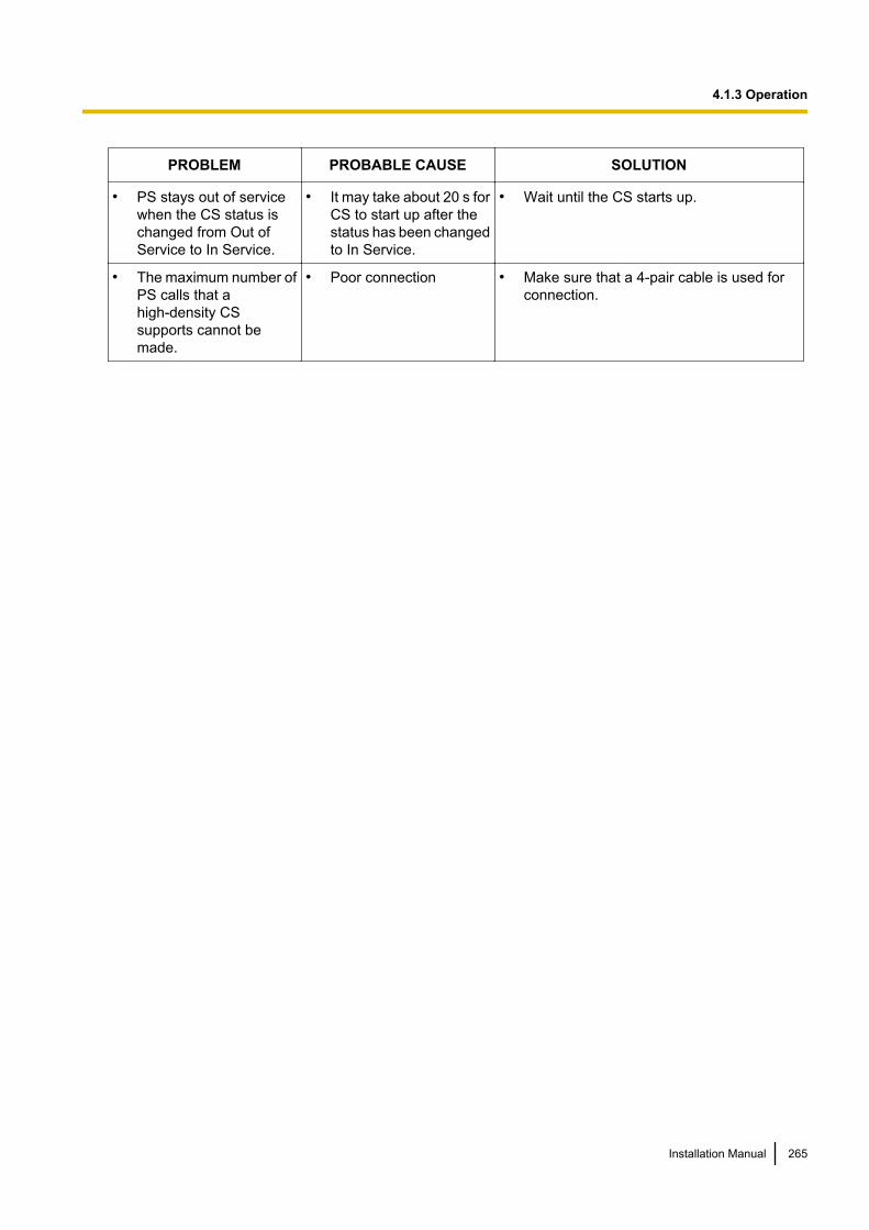
PROBLEM PROBABLE CAUSE SOLUTION
• PS stays out of servicewhen the CS status ischanged from Out ofService to In Service.
• It may take about 20 s forCS to start up after thestatus has been changedto In Service.
• Wait until the CS starts up.
• The maximum number ofPS calls that ahigh-density CSsupports cannot bemade.
• Poor connection • Make sure that a 4-pair cable is used forconnection.
Installation Manual 265
4.1.3 Operation
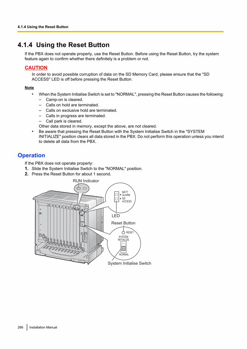
4.1.4 Using the Reset ButtonIf the PBX does not operate properly, use the Reset Button. Before using the Reset Button, try the systemfeature again to confirm whether there definitely is a problem or not.
CAUTIONIn order to avoid possible corruption of data on the SD Memory Card, please ensure that the "SDACCESS" LED is off before pressing the Reset Button.
Note• When the System Initialise Switch is set to "NORMAL", pressing the Reset Button causes the following:
– Camp-on is cleared.– Calls on hold are terminated.– Calls on exclusive hold are terminated.– Calls in progress are terminated.– Call park is cleared.Other data stored in memory, except the above, are not cleared.
• Be aware that pressing the Reset Button with the System Initialise Switch in the "SYSTEMINITIALIZE" position clears all data stored in the PBX. Do not perform this operation unless you intendto delete all data from the PBX.
OperationIf the PBX does not operate properly:1. Slide the System Initialise Switch to the "NORMAL" position.2. Press the Reset Button for about 1 second.
System Initialise Switch
Reset Button
SYSTEMINITIALIZE
RESET
NORMAL
RUN Indicator
BATTALARM
SDACCESS
LED
266 Installation Manual
4.1.4 Using the Reset Button

4.1.5 Troubleshooting by Error LogWhen a major system error occurs in the PBX, the ALARM indicator on the front of the shelf turns on red, andthe system logs the error information.
Error Log Display FormatBelow is the display format of the error log. For information about how to view the error log using theMaintenance Console, refer to "2.6.8 Utility—Error Log" in the PC Programming Manual.
Example: Maintenance Console
1 2 4 5 6
3 7
Example: Station Message Detail Recording (SMDR)
04/01/01 10:37AM MJ ALM #000 10000 MPR WDT overflow
04/01/01 11:07AM MN ALM #010 10000 AC power down
04/01/01 03:55PM MN ALM #301 10501 Digital trunk RAI reception
1 2 3 4 5 6
Description
Item Description
1 Date The date of the error detection.
2 Time The time of the error detection.
3 Level Minor (MN ALM) Displays minor errors, which affect only a certain part of systemoperation.
Major (MJ ALM) Displays major errors, which affect operation of the wholesystem, or result in system failure.
4 Error Code The 3-digit error code assigned by the PBX.
Installation Manual 267
4.1.5 Troubleshooting by Error Log
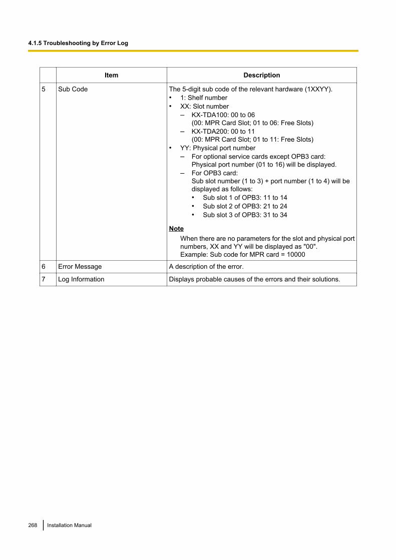
Item Description
5 Sub Code The 5-digit sub code of the relevant hardware (1XXYY).• 1: Shelf number• XX: Slot number
– KX-TDA100: 00 to 06(00: MPR Card Slot; 01 to 06: Free Slots)
– KX-TDA200: 00 to 11(00: MPR Card Slot; 01 to 11: Free Slots)
• YY: Physical port number– For optional service cards except OPB3 card:
Physical port number (01 to 16) will be displayed.– For OPB3 card:
Sub slot number (1 to 3) + port number (1 to 4) will bedisplayed as follows:• Sub slot 1 of OPB3: 11 to 14• Sub slot 2 of OPB3: 21 to 24• Sub slot 3 of OPB3: 31 to 34
NoteWhen there are no parameters for the slot and physical portnumbers, XX and YY will be displayed as "00".Example: Sub code for MPR card = 10000
6 Error Message A description of the error.
7 Log Information Displays probable causes of the errors and their solutions.
268 Installation Manual
4.1.5 Troubleshooting by Error Log

Section 5
Appendix
Installation Manual 269
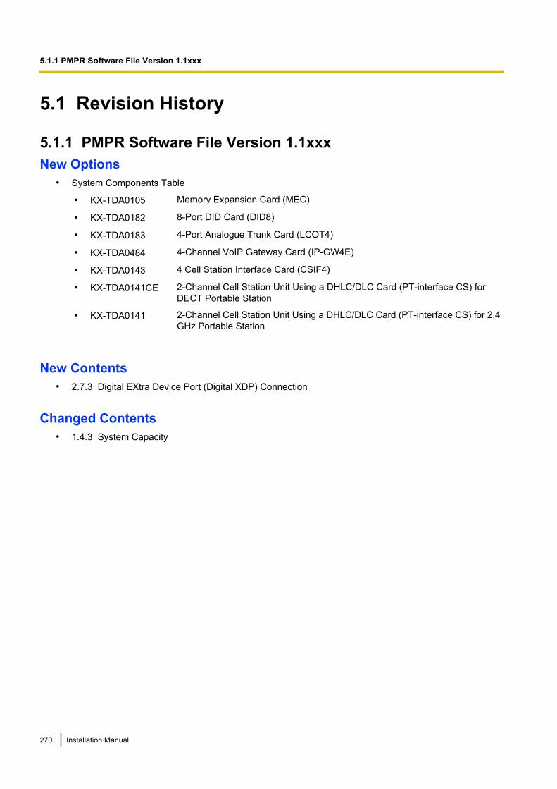
5.1 Revision History
5.1.1 PMPR Software File Version 1.1xxxNew Options
• System Components Table
• KX-TDA0105 Memory Expansion Card (MEC)
• KX-TDA0182 8-Port DID Card (DID8)
• KX-TDA0183 4-Port Analogue Trunk Card (LCOT4)
• KX-TDA0484 4-Channel VoIP Gateway Card (IP-GW4E)
• KX-TDA0143 4 Cell Station Interface Card (CSIF4)
• KX-TDA0141CE 2-Channel Cell Station Unit Using a DHLC/DLC Card (PT-interface CS) forDECT Portable Station
• KX-TDA0141 2-Channel Cell Station Unit Using a DHLC/DLC Card (PT-interface CS) for 2.4GHz Portable Station
New Contents• 2.7.3 Digital EXtra Device Port (Digital XDP) Connection
Changed Contents• 1.4.3 System Capacity
270 Installation Manual
5.1.1 PMPR Software File Version 1.1xxx
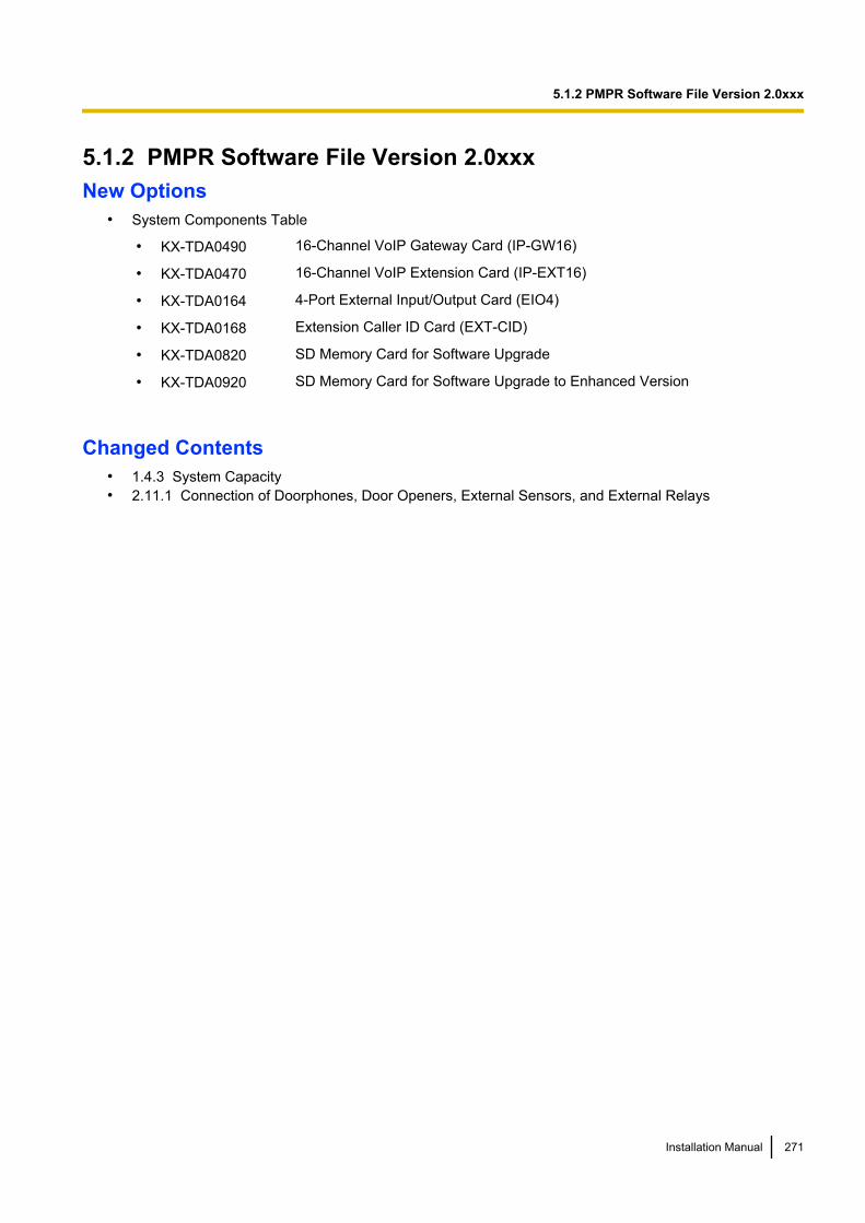
5.1.2 PMPR Software File Version 2.0xxxNew Options
• System Components Table
• KX-TDA0490 16-Channel VoIP Gateway Card (IP-GW16)
• KX-TDA0470 16-Channel VoIP Extension Card (IP-EXT16)
• KX-TDA0164 4-Port External Input/Output Card (EIO4)
• KX-TDA0168 Extension Caller ID Card (EXT-CID)
• KX-TDA0820 SD Memory Card for Software Upgrade
• KX-TDA0920 SD Memory Card for Software Upgrade to Enhanced Version
Changed Contents• 1.4.3 System Capacity• 2.11.1 Connection of Doorphones, Door Openers, External Sensors, and External Relays
Installation Manual 271
5.1.2 PMPR Software File Version 2.0xxx

5.1.3 PMPR Software File Version 3.0xxxChanged Contents
• 1.4.3 System Capacity• 3.3.1 Installing and Starting the Maintenance Console
272 Installation Manual
5.1.3 PMPR Software File Version 3.0xxx
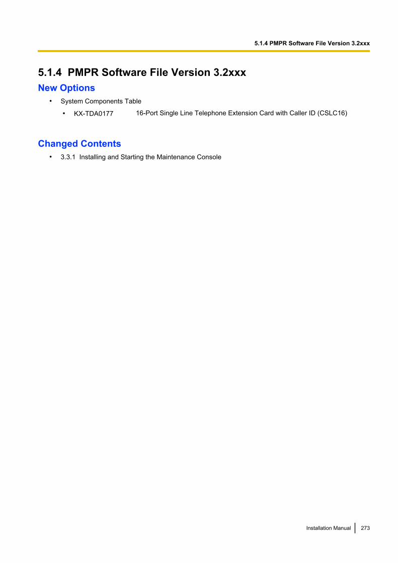
5.1.4 PMPR Software File Version 3.2xxxNew Options
• System Components Table
• KX-TDA0177 16-Port Single Line Telephone Extension Card with Caller ID (CSLC16)
Changed Contents• 3.3.1 Installing and Starting the Maintenance Console
Installation Manual 273
5.1.4 PMPR Software File Version 3.2xxx
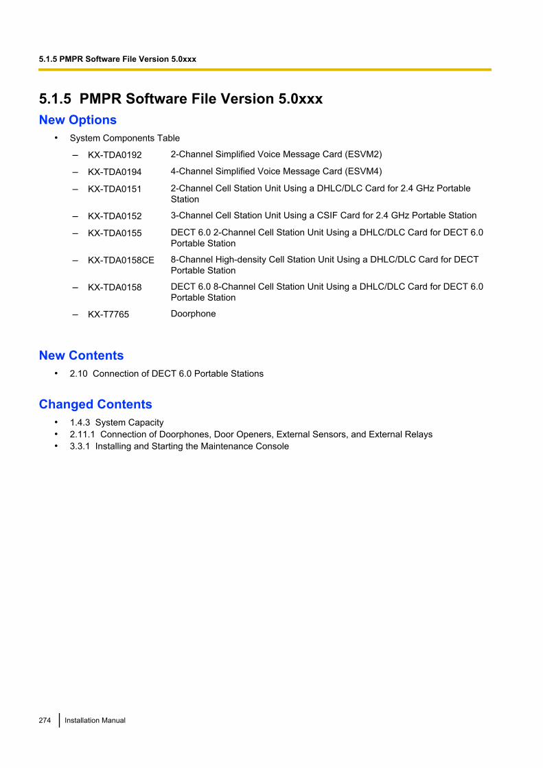
5.1.5 PMPR Software File Version 5.0xxxNew Options
• System Components Table
– KX-TDA0192 2-Channel Simplified Voice Message Card (ESVM2)
– KX-TDA0194 4-Channel Simplified Voice Message Card (ESVM4)
– KX-TDA0151 2-Channel Cell Station Unit Using a DHLC/DLC Card for 2.4 GHz PortableStation
– KX-TDA0152 3-Channel Cell Station Unit Using a CSIF Card for 2.4 GHz Portable Station
– KX-TDA0155 DECT 6.0 2-Channel Cell Station Unit Using a DHLC/DLC Card for DECT 6.0Portable Station
– KX-TDA0158CE 8-Channel High-density Cell Station Unit Using a DHLC/DLC Card for DECTPortable Station
– KX-TDA0158 DECT 6.0 8-Channel Cell Station Unit Using a DHLC/DLC Card for DECT 6.0Portable Station
– KX-T7765 Doorphone
New Contents• 2.10 Connection of DECT 6.0 Portable Stations
Changed Contents• 1.4.3 System Capacity• 2.11.1 Connection of Doorphones, Door Openers, External Sensors, and External Relays• 3.3.1 Installing and Starting the Maintenance Console
274 Installation Manual
5.1.5 PMPR Software File Version 5.0xxx

Index
Installation Manual 275
Numerics16-Channel Echo Canceller Card (KX-TDA0166) 2516-Channel VoIP Extension Card (KX-TDA0470) 27, 12216-Channel VoIP Gateway Card (KX-TDA0490) 27, 10616-Port Analogue Trunk Card (KX-TDA0181) 26, 7816-Port Digital Extension Card (KX-TDA0172) 25, 11416-Port Single Line Telephone Extension Card(KX-TDA0174) 25, 11916-Port Single Line Telephone Extension Card with Caller ID(KX-TDA0177) 26, 11916-Port Single Line Telephone Extension with Message LampCard (KX-TDA0175) 26, 1192-Channel Simplified Voice Message Card(KX-TDA0192) 262-Port Doorphone Card (German Type)(KX-TDA0162) 25, 1272-shelf System, System Capacity 312.4 GHz Portable Station, After Site Survey 1972.4 GHz Portable Station, Before Site Survey 1902.4 GHz Portable Station, Connecting a CS 1982.4 GHz Portable Station, Connection 1822.4 GHz Portable Station, Procedure Overview 1842.4 GHz Portable Station, Site Planning 1862.4 GHz Portable Station, Site Survey 1933-shelf System, System Capacity 314 Cell Station Interface Card (KX-TDA0143) 25, 1084-Channel Message Card (KX-TDA0166) 1334-Channel Message Card (KX-TDA0191) 26, 1344-Channel Simplified Voice Message Card(KX-TDA0194) 264-Channel VoIP Gateway Card (KX-TDA0480) 27, 1024-Channel VoIP Gateway Card (KX-TDA0484) 27, 1044-Port Analogue Trunk Card (KX-TDA0183) 26, 784-Port BRI Card (KX-TDA0284) 27, 924-Port Doorphone Card (KX-TDA0161) 25, 1254-Port External Input/Output Card (KX-TDA0164) 25, 1304-shelf System, System Capacity 318 Cell Station Interface Card (KX-TDA0144) 25, 1088-Port Analogue Trunk Card (KX-TDA0180) 26, 788-Port BRI Card (KX-TDA0288) 27, 928-Port Caller ID Card (KX-TDA0193) 26, 838-Port Caller ID/Pay Tone Card (KX-TDA0189) 26, 828-Port DID Card (KX-TDA0182) 26, 808-Port Digital Extension Card (KX-TDA0171) 25, 1128-Port Digital Hybrid Extension Card(KX-TDA0170) 25, 1108-Port E & M Trunk Card (KX-TDA0184) 26, 848-Port Single Line Telephone Extension Card(KX-TDA0173) 25, 116
AAbout the software version of your PBX 14Amphenol Connector 63, 64Appendix 269
BBackup Battery Connection 51Backup Power Supply Duration 51Basic Shelf 22Basic Shelf, Construction 22Basic Shelf, Names and Locations 43
Basic System, System Capacity 31BGM 241Blank Slot Cover 55BRI4 Card (KX-TDA0284) 92BRI8 Card (KX-TDA0288) 92
CCable Distance 138Cable Handling 56Changed Contents 270, 271, 272, 273, 274Characteristics 30CID/PAY8 Card (KX-TDA0189) 82CID8 Card (KX-TDA0193) 83Components, System 2Connecting Backup Batteries 51Connection Diagram, System 23Connector Types 58Cover for Blank Slot 55CS (for 2.4 GHz Portable Station) 198CS (for DECT 6.0 Portable Station) 229CS (for DECT Portable Station) 169CSIF4 Card (KX-TDA0143) 108CSIF8 Card (KX-TDA0144) 108CSLC16 Card (KX-TDA0177) 119CTI Link Card (KX-TDA0410) 27, 136CTI Server Connection (via USB version 2.0) 244CTI—First Party Call Control 150CTI-LINK Card (KX-TDA0410) 136CTI—Third Party Call Control 136, 244
DDECT 6.0 Portable Station, After Site Survey 228DECT 6.0 Portable Station, Before Site Survey 219DECT 6.0 Portable Station, Connecting a CS 229DECT 6.0 Portable Station, Connection 211DECT 6.0 Portable Station, Procedure Overview 213DECT 6.0 Portable Station, Site Planning 215DECT 6.0 Portable Station, Site Survey 224DECT Portable Station, After Site Survey 168DECT Portable Station, Before Site Survey 159DECT Portable Station, Connecting a CS 169DECT Portable Station, Connection 151DECT Portable Station, Procedure Overview 153DECT Portable Station, RF Specification 151DECT Portable Station, Site Planning 155DECT Portable Station, Site Survey 164DHLC8 Card (KX-TDA0170) 110DID8 Card (KX-TDA0182) 80Digital EXtra Device Port (Digital XDP) Connection 143Digital XDP 143Digital XDP Connection, Using a ModularT-Adaptor 143, 145, 147Digital XDP Connection, Using an EXtra DevicePort 144, 146, 148DLC16 Card (KX-TDA0172) 114DLC8 Card (KX-TDA0171) 112Door Opener 125, 127, 238Doorphone 125, 127, 238DPH2 Card (KX-TDA0162) 127DPH4 Card (KX-TDA0161) 125
276 Installation Manual
Index
EE&M8 Card (KX-TDA0184) 84E-1 Trunk Card (KX-TDA0188) 26, 89E1 Card (KX-TDA0188) 89ECHO16 Card (KX-TDA0166) 133EIO4 Card (KX-TDA0164) 130Error Log 267Examples 51Expansion Shelf, Names and Locations 43EXT-CID Card (KX-TDA0168) 118Extension Caller ID Card (KX-TDA0168) 25, 118External Relay 130, 132, 238External Sensor 130, 132, 238EXtra Device Port (XDP) Mode 140, 143
FFerrite Core 60First Party Call Control CTI Connection 150Floor Standing (KX-TDA200 Only) 69Frame Earth Connection 50Front Cover, Closing 45Front Cover, Opening 44
IInstallation Precautions 40IP-EXT16 Card (KX-TDA0470) 122IP-GW16 Card (KX-TDA0490) 106IP-GW4 Card (KX-TDA0480) 102IP-GW4E Card (KX-TDA0484) 104
KKX-TDA0103 (L-Type Power Supply Unit) 25, 46KX-TDA0104 (M-Type Power Supply Unit) 25, 46KX-TDA0105 (Memory Expansion Card) 25, 76KX-TDA0108 (S-Type Power Supply Unit) 25, 46KX-TDA0143 (4 Cell Station Interface Card) 25, 108KX-TDA0144 (8 Cell Station Interface Card) 25, 108KX-TDA0161 (4-Port Doorphone Card) 25, 125KX-TDA0162 (2-Port Doorphone Card [GermanType]) 25, 127KX-TDA0164 (4-Port External Input/Output Card) 25, 130KX-TDA0166 (16-Channel Echo Canceller Card) 25, 133KX-TDA0168 (Extension Caller ID Card) 25, 118KX-TDA0170 (8-Port Digital Hybrid ExtensionCard) 25, 110KX-TDA0171 (8-Port Digital Extension Card) 25, 112KX-TDA0172 (16-Port Digital Extension Card) 25, 114KX-TDA0173 (8-Port Single Line Telephone ExtensionCard) 25, 116KX-TDA0174 (16-Port Single Line Telephone ExtensionCard) 25, 119KX-TDA0175 (16-Port Single Line Telephone Extension withMessage Lamp Card) 26, 119KX-TDA0177 (16-Port Single Line Telephone Extension Cardwith Caller ID) 26, 119KX-TDA0180 (8-Port Analogue Trunk Card) 26, 78KX-TDA0181 (16-Port Analogue Trunk Card) 26, 78KX-TDA0182 (8-Port DID Card) 26, 80KX-TDA0183 (4-Port Analogue Trunk Card) 26, 78KX-TDA0184 (8-Port E & M Trunk Card) 26, 84
KX-TDA0187 (T-1 Trunk Card) 26, 86KX-TDA0188 (E-1 Trunk Card) 26, 89KX-TDA0189 (8-Port Caller ID/Pay Tone Card) 26, 82KX-TDA0190 (Optional 3-Slot Base Card) 26, 124KX-TDA0191 (4-Channel Message Card) 26, 134KX-TDA0192 (2-Channel Simplified Voice MessageCard) 26KX-TDA0193 (8-Port Caller ID Card) 26, 83KX-TDA0194 (4-Channel Simplified Voice MessageCard) 26KX-TDA0196 (Remote Card) 26, 77KX-TDA0284 (4-Port BRI Card) 27, 92KX-TDA0288 (8-Port BRI Card) 27, 92KX-TDA0290 (PRI Card [PRI23]) 27, 99KX-TDA0290CE/KX-TDA0290CJ (PRI Card[PRI30]) 27, 96KX-TDA0410 (CTI Link Card) 27, 136KX-TDA0470 (16-Channel VoIP Extension Card) 27, 122KX-TDA0480 (4-Channel VoIP Gateway Card) 27, 102KX-TDA0484 (4-Channel VoIP Gateway Card) 27, 104KX-TDA0490 (16-Channel VoIP Gateway Card) 27, 106KX-TDA0820 (SD Memory Card for SoftwareUpgrade) 27, 74KX-TDA0920 (SD Memory Card for Software Upgrade toEnhanced Version) 27, 74
LL-Type Power Supply Unit (KX-TDA0103) 25, 46LCOT16 Card (KX-TDA0181) 78LCOT4 Card (KX-TDA0183) 78LCOT8 Card (KX-TDA0180) 78LED Indications, PBX 250Load Figure Calculation 37
MM-Type Power Supply Unit (KX-TDA0104) 25, 46Main Processing Card (MPR Card) 74Maintenance Console 252Maintenance Console, Connection 253Maintenance Console, Installation 256Maintenance Console, Overview 252Maintenance Console, Password Security 255Maintenance Console, Quick Setup 256Maintenance Console, System Requirements 255Master DPT, Digital XDP 143Maximum Optional Service Cards 31Maximum Terminal Equipment 35MEC Card (KX-TDA0105) 76MEC Card Calculation 36Memory Expansion Card (KX-TDA0105) 25, 76MOH 241MPR Card 74MSG4 Card (KX-TDA0191) 134MSLC16 Card (KX-TDA0175) 119
NNames and Locations 43New Contents 270, 274New Options 270, 271, 273, 274
Installation Manual 277
Index

OOPB3 Card (KX-TDA0190) 124Optional 3-Slot Base Card (KX-TDA0190) 26, 124Optional Equipment 25Optional Service Card, Installation 53Optional Service Card, Maximum Number 31Optional Service Card, Removal 57
PPager 242Panasonic Proprietary Telephones, Compatible 4Panasonic Proprietary Telephones, Incompatible 4Parallel Connection of the Extensions 140Parallel Connection, Using a Modular T-Adaptor 141Parallel Connection, Using an EXtra Device Port 141Parallel Mode 140, 143Password Security 255PC Connection (via RS-232C) 242PC Connection (via USB version 2.0) 244PMPR Software File Version 1.1xxx 270PMPR Software File Version 2.0xxx 271PMPR Software File Version 3.0xxx 272PMPR Software File Version 3.2xxx 273PMPR Software File Version 5.0xxx 274Power Failure Connections 245Power Supply Unit 46Power Supply Unit Selection 37Power Supply Unit, Installation 47Power Supply Unit, Replacement 48PRI Card (PRI23) (KX-TDA0290) 27, 99PRI Card (PRI30) (KX-TDA0290CE/CJ) 27PRI Card (PRI30) (KX-TDA0290CE/KX-TDA0290CJ) 96PRI23 Card (KX-TDA0290) 99PRI30 Card (KX-TDA0290CE/KX-TDA0290CJ) 96Printer Connection (via RS-232C) 242PSU 46PSU Capacity 37PSU-L 37, 46PSU-M 37, 46PSU-S 37, 46
QQuick Setup 256
RRemote Card (KX-TDA0196) 26, 77Reset Button 266Revision History 270RF Specification, DECT 6.0 Portable Station 212RF Specification, DECT Portable Station 151RMT Card (KX-TDA0196) 77RUN Indicator 249
SS-Type Power Supply Unit (KX-TDA0108) 25, 46Safety Installation Instructions 40Safety Instructions 46SD Memory Card 74
SD Memory Card for Software Upgrade(KX-TDA0820) 27, 74SD Memory Card for Software Upgrade to Enhanced Version(KX-TDA0920) 27, 74Site Planning, 2.4 GHz Portable Station 186Site Planning, DECT 6.0 Portable Station 215Site Planning, DECT Portable Station 155Site Survey, 2.4 GHz Portable Station 193Site Survey, DECT 6.0 Portable Station 224Site Survey, DECT Portable Station 164Slave DPT, Digital XDP 143SLC16 Card (KX-TDA0174) 119SLC8 Card (KX-TDA0173) 116Specifications 28Specifications, Characteristics 30Specifications, General Description 28Specifications, System Capacity 31Starting the PBX 249Surge Protector Installation 71System Capacity 31System Components Table 2System Connection Diagram 23System Highlights 20System Initialisation Procedure 249System Initialise Switch 249, 266System Requirements 255
TT-1 Trunk Card (KX-TDA0187) 26, 86T1 Card (KX-TDA0187) 86Terminal Equipment, Maximum Number 35Troubleshooting, by Error Log 267Troubleshooting, Connection 261Troubleshooting, Installation 260Troubleshooting, Operation 263Troubleshooting, Using the Reset Button 266Trunk Connection 250
UUnpacking 42
WWall Mounting (CS) 178, 206, 235Wall Mounting (KX-TDA100) 67Wall Mounting (KX-TDA200) 65Wiring Precautions 40
278 Installation Manual
Index
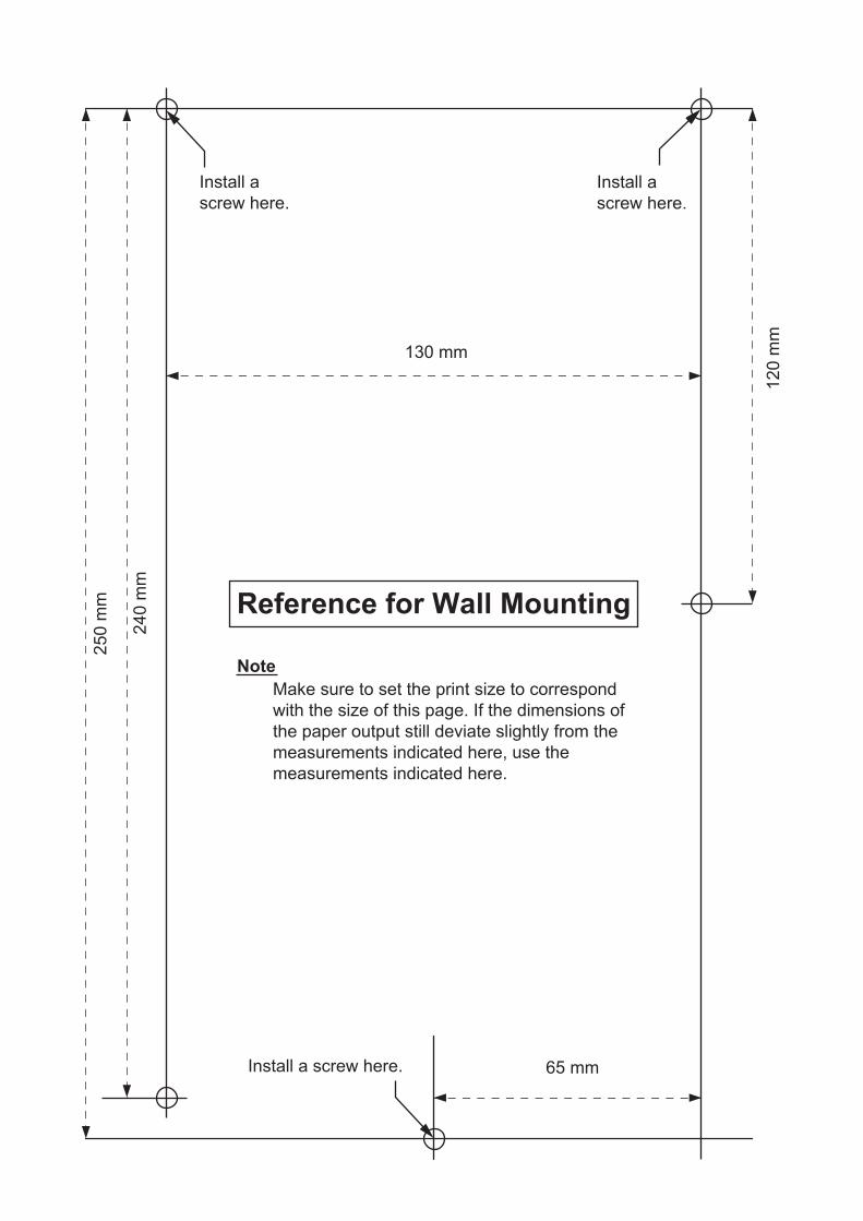
25
0 m
m
24
0 m
m
65 mm
130 mm
12
0 m
m
Reference for Wall Mounting
Install a screw here.
Install a
screw here.
Install a
screw here.
Note
Make sure to set the print size to correspond
with the size of this page. If the dimensions of
the paper output still deviate slightly from the
measurements indicated here, use the
measurements indicated here.
The KX-TDA100E/KX-TDA200E, the KX-TDA100NE/KX-TDA200NE, the KX-TDA100GR/KX-TDA200GR, and
the KX-TDA100CE/KX-TDA200CE are designed to interwork with the:
• Analogue Public Switched Telephone Network (PSTN) of European countries
• Pan-European Integrated Services Digital Network (ISDN) using ISDN basic rate access
• Pan-European Integrated Services Digital Network (ISDN) using ISDN primary rate
access
• ONP 2048 kbit/s digital structured leased lines (D2048S)
Panasonic Communications Co., Ltd./Panasonic Communications Company (U.K.) Ltd. declares that this equipment is in
compliance with the essential requirements and other relevant provisions of Radio & Telecommunications Terminal
Equipment (R&TTE) Directive 1999/5/EC.
Declarations of Conformity for the relevant Panasonic products described in this manual are available for download by
visiting:
http://www.doc.panasonic.de
Contact to Authorised Representative:
Panasonic Testing Centre
Panasonic Marketing Europe GmbH
Winsbergring 15, 22525 Hamburg, Germany

Installation Manual 281
Notes
1-62, 4-chome, Minoshima, Hakata-ku, Fukuoka 812-8531, Japan
PSQX2633SA
Copyright:
This material is copyrighted by Panasonic Communications Co., Ltd., and may be reproduced for internal use
only. All other reproduction, in whole or in part, is prohibited without the written consent of Panasonic
Communications Co., Ltd.
Panasonic Communications Co., Ltd. 2003
KK0103AH9118
For Future Reference
Please print, record, and retain the following information for future reference.
The serial number of this product can be found on the label affixed to the unit. You should record
the model number and the serial number of this unit as a permanent record of your purchase to
aid in identification in the event of theft.
Note
MODEL NO.
SERIAL NO.
DATE OF PURCHASE
NAME OF DEALER
DEALER'S ADDRESS
DEALER'S TEL. NO.