INSTALLATION MANUAL INMARSAT-C MOBILE EARTH STATION FELCOM 12 · installation manual inmarsat-c...
43
INSTALLATION MANUAL INMARSAT-C MOBILE EARTH STATION FELCOM 12 1. SYSTEM CONFIGURATION ................................. 1 2. EQUIPMENT LIST ................................................. 2 3. MOUNTING THE EQUIPMENT ............................. 3 4. WIRING ................................................................. 7 5. INSTALLATION OF GPS BOARD ASSEMBLY (OPTION) ............................................................. 11 6. CHANGING POWER SPECIFICATION ............. 12 Installation Materials, Spare Parts, Accessories ........................................................... A-1 Outline Drawings ................................................... D-1 Interconnection and Schematic Diagrams .......... S-1 NISHINOMIYA, JAPAN R
Transcript of INSTALLATION MANUAL INMARSAT-C MOBILE EARTH STATION FELCOM 12 · installation manual inmarsat-c...

INSTALLATION MANUALINMARSAT-C
MOBILE EARTH STATIONFELCOM 12
1. SYSTEM CONFIGURATION ................................. 1
2. EQUIPMENT LIST ................................................. 2
3. MOUNTING THE EQUIPMENT ............................. 3
4. WIRING ................................................................. 7
5. INSTALLATION OF GPS BOARD ASSEMBLY(OPTION) ............................................................. 11
6. CHANGING POWER SPECIFICATION ............. 12
Installation Materials, Spare Parts,Accessories ........................................................... A-1
Outline Drawings ................................................... D-1
Interconnection and Schematic Diagrams .......... S-1
NISHINOMIYA, JAPAN
R

C
9 - 5 2 , A s h i h a r a - c h o , N i s h i n o m i y a , J a p a n
Te l e p h o n e : 0 7 9 8 - 6 5 - 2 111 Te l e f a x : 0 7 9 8 - 6 5 - 4 2 0 0
Yo u r L o c a l A g e n t / D e a l e r
A l l r i g h t s r es e r ve d .
P UB . No . IM E - 5 6 1 30 - K F E L C O M 1 2 (T E N I )
F IR S T E D I T I O N : N O V. 1 9 9 7 K : A U G . 7 , 2 0 0 0 Printed in Japan

iiiiiiiiiiiii i
Ground the equipment toprevent electrical shockand mutual interference.
Confirm that the power supply voltageis compatible with the voltage ratingof the equipment.
Connection to the wrong power supply can cause fire or equipment damage. Thevoltage rating appears on the label at therear of the display unit.
Keep the following compass safedistances:
CAUTION
SAFETY INSTRUCTIONS
Standard Steering
IC-112 0.6 m 0.5 m
IC-212 1.8 m 1.3 m
IB-581 1.4 m 1.0 m
IC-302IC-303 0.8 m 0.6 m
PP-510 1.0 m 0.8 m
PR-300 0.9 m 0.7 m
Do not work inside theequipment unless totallyfamiliar with electricalcircuits.
Hazardous voltage which cancause electrical shock, burnor serious injury exists insidethe equipment.
Do not approach theradome closer than 60 cmwhen it is transmitting.
Microwave radiation cancause severe injury or illness.Radiation level:10 W/m2 at 60 cm
Turn off the power at the mains switchboard before beginning the installation.Post a sign near the switch to indicate it should not beturned on while the equip-ment is being installed.
Fire, electrical shock or serious injury can result if the power is left on or is applied while the equipment is beinginstalled.
Do not install the equipment whereflammable gases are stored.
Fire may result.
WARNING

1
1. SYSTEM CONFIGURATION
Antenna UnitIC-112
Ground wire
Ship’s mains24 VDC
AC/DC PowerSupply UnitPR-300
Ship’s mains100/200 VAC
24 VDC
Communication UnitIC-212
Terminal UnitIB-581
Keyboard
PrinterPP-510
24 VDC
Distress Alert UnitIC-302
Received Call UnitIC-303
Terminal UnitIB-581
24 VDC
24 VDC
EGC PrinterPP-505
Terminal UnitIB-581or IBM Compatibile Personal Computer
External Navigation Device
I/F BoxOP16-14
: Standard Supply
: Optional Supply
*: Mandatory for EGC operation as required by IMO Res. A. 664(16).
Figure 1-1 System configuration
*

2
2. EQUIPMENT LIST
Standard Supply
Optional Equipment
.oN emaN epyTssaM)gk(
ytQ skrameR
1 tinUannetnA 211-CI 5.4 1,11510-61PCslairetam.tsnisedulcnI
egapeeS(,13510-61PCro12510-61PC.yssaelbaC&).6-Aot4-A
2 tinUnoitacinummoC 212-CI 4 1
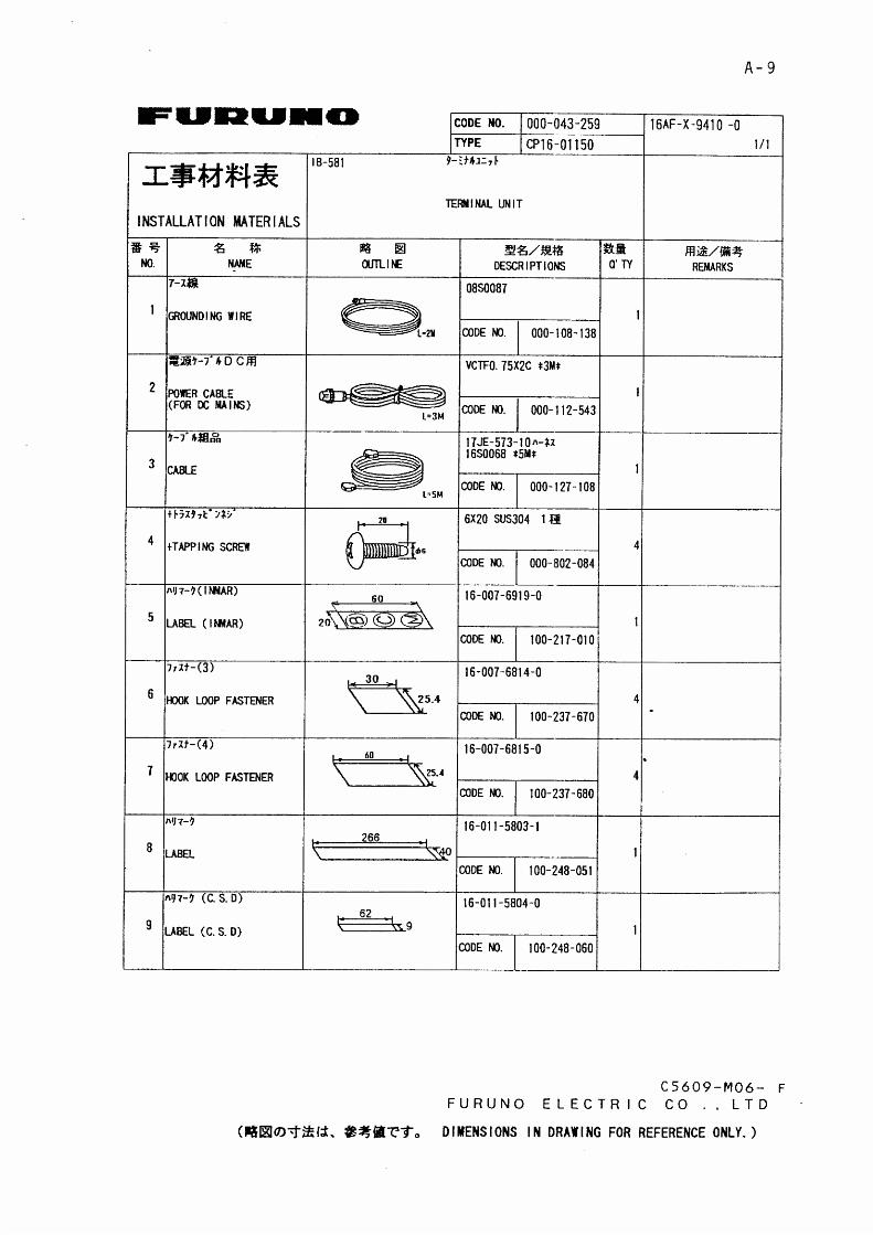
3 tinUlanimreT 185-BI 6 1.tsnisedulcnI
).9-AegapeeS(slairetam
4 tinUtrelAssertsiD 203-CI 4.0 2
5 tinUllaCdevieceR 303-CI 4.0 1
6 slairetaMnoitallatsnI 00510-61PC tes1).2-AegapeeS(10510-61PC
stes3———20510-61PC).3-AegapeeS(
7 seirosseccA 00300-61PF tes1 .1-AegapeeS
.oN emaN epyTssaM)gk(
.oNedoC skrameR
1ylppuSrewoPCD-CA
tinU003-RP 5.41 -
2 retnirP 015-PP 6.3 - repapllordedulcnI
3 retnirP 505-PP 1.3 -
4 tinUlanimreT 185-BI 6 -
5 straPecnanetniaM 00110-61PS - 013-734-400 .01-AegapeeS
6erawtfoSlanimreT
elbac/w21005-CI - 023-734-400 srotcennocP9-P9
A21005-CI - 033-734-400 srotcennocP52-P9
7 .yssAdraoBSPG 1-61-61PO - 053-734-400 .yrotcaftadettiF
2-61-61PO - 043-734-400 .11egapeeS.dleifnillatsnI
8noitallatsnIannetnA
lairetam21510-61PC - 003-734-400 .31-AegapeeS

3
3. MOUNTING THE EQUIPMENT
5) Avoid the location near funnels and stacks;smoke and soot on the radome can lower sig-nal level.
6) Never mount the antenna unit on a metalplate more than 20 cm square. Use the an-tennal mounting pipe (supplied), or fix orweld it to a bracket as shown below.
more than20 cm
more than20 cm
Welding Use bracketand hose clamp(local supply)
Figure 3-3 Mounting the antenna
Mounting Location
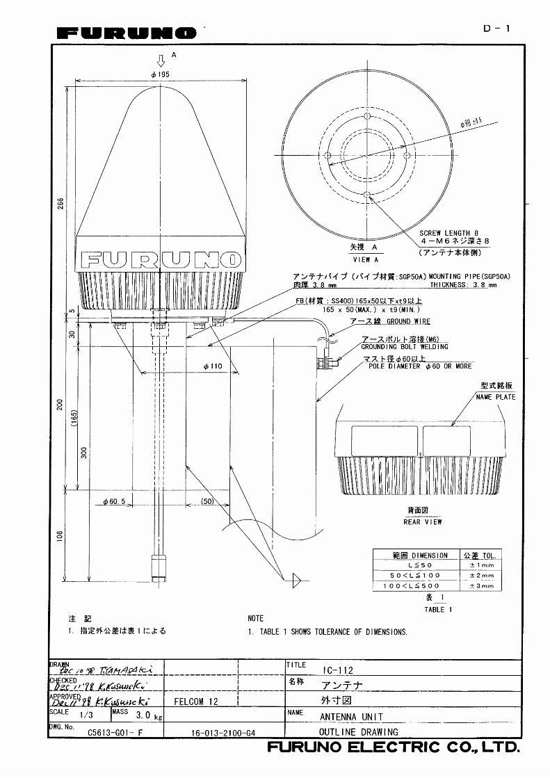
Antenna unit
1) Mount the omnidirectional antenna high atopa mast clear of stays and the turning diam-eter of a radar scanner. The ideal mountinglocation would be where no obstacle appearsin the fore and aft directions down to -5˚ anddown to -15˚ in the port and starboard direc-tions. This concept is illustrated inFigure 3-1. Shadow sector of the antennamast, whip antenna, etc. should be within 2degrees at one meter from the antenna unit.
ANTENNA UNIT
5̊5̊ 15˚ 15˚
Figure 3-1 Antenna unit mounting location
2) If both Inmarsat-A/B and Inmarsat-C shipearth stations are installed, separate theInmarsat-A/B antenna at least 8 m from theInmarsat-C antenna.
3) Separate the antenna unit from an S-bandradar as follows:
2 m
2 m 5 m
S band radar
1.5 m
HORIZONTAL LINE
Install above this line
PROHIBITED ZONE
INSTALLATION ZONE
15˚
Figure 3-2 S band radar and installation area
4) The allowable vibration level as specified byInmarsat is as shown in the table below.
Table 3-1 Allowable vibration level
ycneuqerF leveL
zH01ot2 edutilpmAkaePmm45.2
zH001ot01 s/m8.9 2 noitareleccAkaeP
4
Communication unit
1) The communication unit can be installed al-most anywhere provided the location satis-fies the following conditions:
•The ambient temperature is between-15˚C and +55˚C.
•Avoid installing the unit near air conditionersand hot air vents.
•Select a location free of water splash and rain.•Select a location where vibration is minimal.•Locate the unit well away from magneticfields (generator, etc.).
•Keep the unit out of direct sunlight.
2) The communication unit can be installed ona tabletop or a bulkhead. For bulkheadmounting be sure the mounting location isstrong enough to support the weight of theunit (4 kg) under the continued condition ofvibration normally encountered onboard thevessel.
3) Leave at least 150 mm at the rear of the unitto permit easy access to connectors.
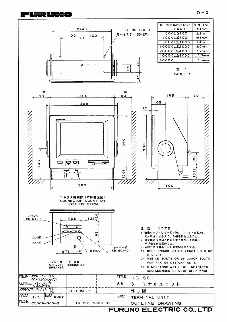
Terminal unit
1) Observe installation guideline 1) above.
2) The installation angle must not be greaterthan 15˚ to prevent disk drive malfunction.
Distress alert unit
Two units should be installed and one shouldbe installed near the steering place.
Mounting
Antenna unit
procedure
1. Locally prepare an antenna mast with aground stud (M6 stainless steel bolt weldedto antenna mast). (The distance between thestud and the ground terminal on the antennaunit should be within 370 mm, which also isthe length of the supplied ground wire.)
2. Weld the antenna mounting pipe (supplied)to the antenna mast. (more than 60 ).
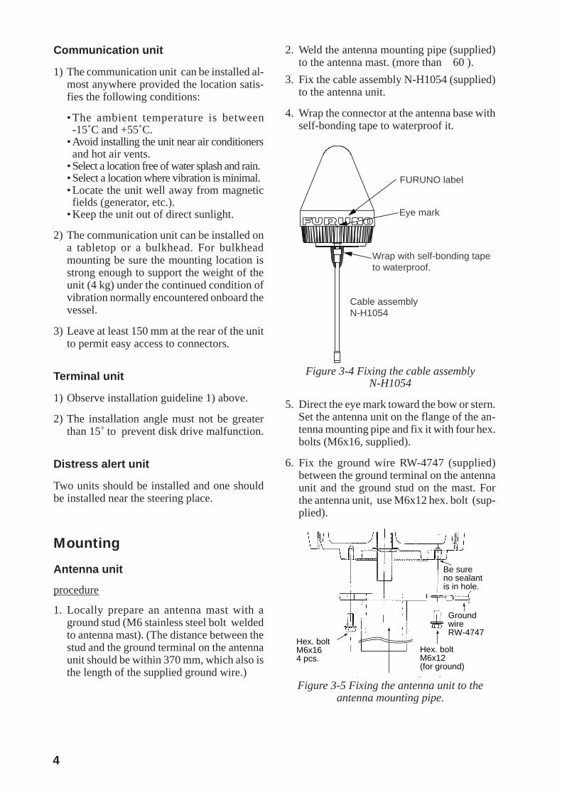
3. Fix the cable assembly N-H1054 (supplied)to the antenna unit.
4. Wrap the connector at the antenna base withself-bonding tape to waterproof it.
Cable assemblyN-H1054
Wrap with self-bonding tapeto waterproof.
FURUNO label
Eye mark
Figure 3-4 Fixing the cable assemblyN-H1054
5. Direct the eye mark toward the bow or stern.Set the antenna unit on the flange of the an-tenna mounting pipe and fix it with four hex.bolts (M6x16, supplied).
6. Fix the ground wire RW-4747 (supplied)between the ground terminal on the antennaunit and the ground stud on the mast. Forthe antenna unit, use M6x12 hex. bolt (sup-plied).
Hex. boltM6x16 4 pcs.
Hex. boltM6x12 (for ground)
A t ti i
GroundwireRW-4747
Be sureno sealantis in hole.
Figure 3-5 Fixing the antenna unit to theantenna mounting pipe.

5
7. Coat bolts with sealant (supplied)
Figure3-6 Antenna unit mounting
Apply sealant all over thevolt/washers/crimp- on lug.
Figure 3-7 Coating bolts with sealant
Note 1: Be sure no sealant enters the bolt holeof the ground terminal
Note 2: The "antenna installation materials Kit"(optional supply) is available to fix theantennamounting pipe to an antenna mast.
Antenna installation materials (option)Type: CP16-01512Code. number: 004-437-300
Table 3-2 Optional antenna inst. materials
emaN epyT ytQ
1 pmalcesoH 303SUS0836.oN 2
2 daehlavOwercs W0072C21x3M 6
3 1erutxifepiP 1602-310-61 1
4 2erutxifepiP 2602-310-61 2
*
After connnecting, wrap connector with self-bonding tape and then vinyl tape. Bind the tape end with a cable tie.
*
POLE DIAMETER(Ø60-90)
HOSE CLAMP x 2
PIPE FIXTURE 1
PIPE FIXTURE 2
: Antenna installation Materials
*
*
Figure 3-8 Mounting the antenna withoptional antenna installation materials
Communication unit
1. Fix the hanger on a table with six tappingscrews.
23779
82
Figure 3-9 Hanger for communication unit
2. Set knobs and washers to communicationunit. Set the communication unit to thehanger and tighten knobs.
Antennamountingpipe
Ground wire(370 mm)
Ground stud
After connnecting, wrap connector with self-bonding tape and then vinyl tape. Bind the tape end with a cable tie. Then fasten the connectorwith cable band.
Tape here to preventcable damage.
Fasten the cable withcable bands.
Apply sealant
Antenna Mast

6
Terminal unit
Leave at least 80 mm at the sides and rear topermit the checking and maintenance.
1. Fix the hanger on a table with four tappingscrews.
2. Attach connectors from external equipmentto bottom panel.
PRINTER
COM1 COM2 K-BOARD
24VDC
Keyboard
Printer
Ship’s Mains 24VDCNot used
CommunicationUnit
Figure 3-10 IB-581, bottom view
3. Screw knobs in terminal unit and set the ter-minal unit to the hanger.
4. Adjust the display screen so it can be easilyviewed. Tighten knobs.
Keyboard
1. Attach the four “hook loop fasteners 3”(small) to the bottom of the keyboard.
2. Attach the four “hook loop fasteners 4”(large) to the “hook loop fasteners 3” at-tached to the keyboard bottom.
3. Remove seals from the “hook loop fasteners4”.
4. Set the keyboard on the mounting locationand press down firmly.
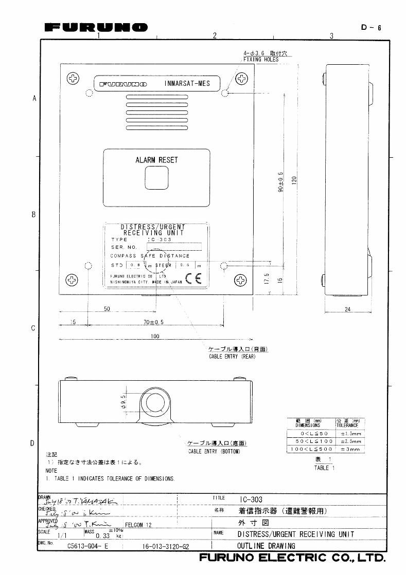
Distress alert unit IC-302 and Distress/Urgent receiving unit IC-303
One IC-302 should be installed near Terminalunit. And the other one should be installed withDistress/Urgent receiving unit at the steeringplace.
1. Remove four screws from the units to sepa-rate the bottom chassis from the top chassis.
2. Fix the bottom chassis to the mounting lo-cation with four tapping screws (supplied).
3. Run the interconnection cable thru a cableentrance (see note below) and connect it toterminal board. Fasten top chassis with fourscrews.
Terminal board
Cable entrance
Figure 3-11 Mounting the lower chassis ofIC-302/IC-303
Note: There are two cable entrances: bottompanel and rear panel. Select suitableentrance and cover unused entrancewith hole plug (supplied).
Printer PP-510 (option)
Mandatory for EGC operation as required byIMO Res. A. 664(16).
Lay the printer on a table and fix it with printerfixtures 1 and 2.
405200
PrinterFixture 1
PrinterFixture 2
Figure 3-12 Mounting the printer PP-510
Printer PP-505 (option)
1. Fix the hanger on a table with four tappingscrews.
2. Screw knobs into printer. Set printer tohanger and tighten knobs.
AC/DC power supply unit
• Fix the unit on a table with four tappingscrews.
7
XXXXXXXXXXXXXXXXXX XXXXXXXXXXXX
XXXX XXXX XXXX
XXXX
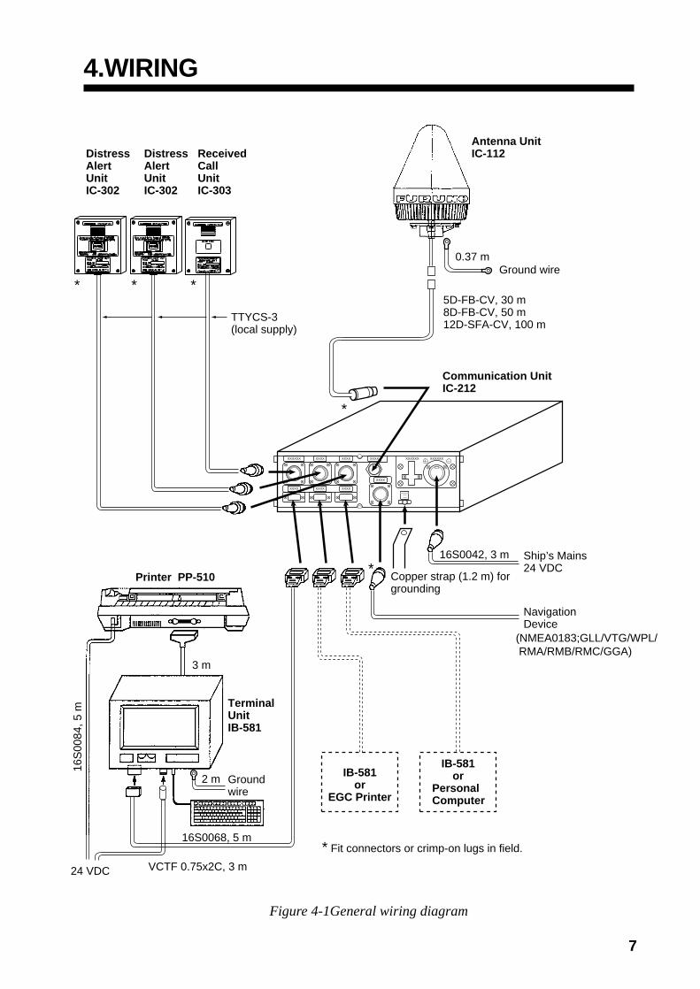
Copper strap (1.2 m) for grounding
16S0042, 3 m
* Fit connectors or crimp-on lugs in field.
Ship’s Mains24 VDC
NavigationDevice
IB-581or
Personal Computer
IB-581or
EGC Printer
16S0068, 5 m
VCTF 0.75x2C, 3 m24 VDC
16S
0084
, 5 m
3 m
2 m
Terminal UnitIB-581
Printer PP-510
Groundwire
Ground wire
Antenna UnitIC-112
Communication UnitIC-212
DistressAlertUnitIC-302
DistressAlertUnitIC-302
ReceivedCallUnitIC-303
5D-FB-CV, 30 m8D-FB-CV, 50 m12D-SFA-CV, 100 m
*
*
0.37 m
TTYCS-3(local supply)
(NMEA0183;GLL/VTG/WPL/ RMA/RMB/RMC/GGA)
* * *
4.WIRING
Figure 4-1General wiring diagram
8
Cable Fabrication, Connector Attachment
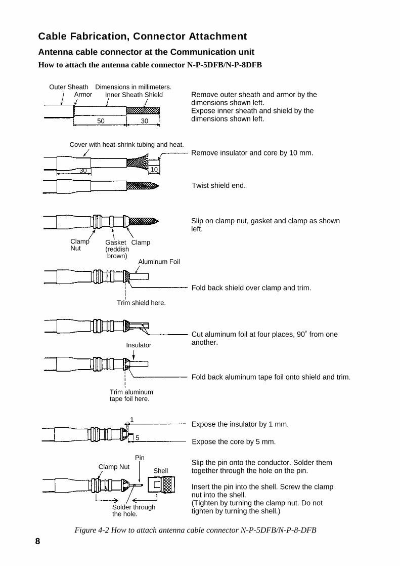
Antenna cable connector at the Communication unitHow to attach the antenna cable connector N-P-5DFB/N-P-8DFB
Outer SheathArmor
Dimensions in millimeters.Inner Sheath Shield
50 30
Cover with heat-shrink tubing and heat.
1030
ClampNut
Gasket(reddish brown)
Clamp
Aluminum Foil
Trim shield here.
Insulator
Trim aluminumtape foil here.
1
5
Clamp NutPin
Shell
Solder throughthe hole.
Remove outer sheath and armor by the dimensions shown left.Expose inner sheath and shield by the dimensions shown left.
Remove insulator and core by 10 mm.
Twist shield end.
Slip on clamp nut, gasket and clamp as shown left.
Fold back shield over clamp and trim.
Cut aluminum foil at four places, 90˚ from one another.
Fold back aluminum tape foil onto shield and trim.
Expose the insulator by 1 mm.
Expose the core by 5 mm.
Slip the pin onto the conductor. Solder them together through the hole on the pin.
Insert the pin into the shell. Screw the clamp nut into the shell.(Tighten by turning the clamp nut. Do not tighten by turning the shell.)
Figure 4-2 How to attach antenna cable connector N-P-5DFB/N-P-8-DFB

9
How to attach the antenna cable connector N-P-12DSFA
Outer SheathArmor
Dimensions in millimeters.Inner Sheath Shield
80 12
Remove outer sheath and armor by the dimensions shown left.Expose inner sheath and shield by the dimensions shown left.
Twist shield end.
Nut
WasherGasket Clamp
Slip on clamp nut, gasket and clamp as shown left.
1.8
4.5
Expose the insulator by 1.8 mm.
Expose the core by 4.5 mm.
Clamp NutPin
Shell
Solder through the hole.
Slip the pin onto the conductor. Solder them together through the hole on the pin.
Insert the pin into the shell. Screw the clamp nut into the shell.(Tighten by turning the clamp nut. Do not tighten by turning the shell.)
Figure 4-3 How to attach antenna cable connector N-P-12-DSFA
10
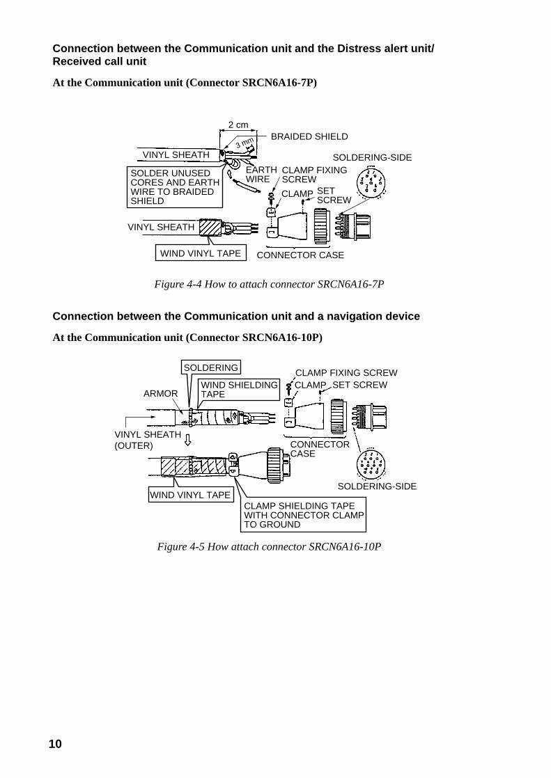
Connection between the Communication unit and the Distress alert unit/Received call unit
At the Communication unit (Connector SRCN6A16-7P)
VINYL SHEATH
VINYL SHEATH
SOLDER UNUSEDCORES AND EARTH WIRE TO BRAIDED SHIELD
WIND VINYL TAPE CONNECTOR CASE
EARTHWIRE
CLAMP FIXINGSCREW
CLAMP SETSCREW
2 cmBRAIDED SHIELD
SOLDERING-SIDE3 mm
Figure 4-4 How to attach connector SRCN6A16-7P
Connection between the Communication unit and a navigation device
At the Communication unit (Connector SRCN6A16-10P)
SOLDERING-SIDE
CLAMP SHIELDING TAPEWITH CONNECTOR CLAMPTO GROUND
WIND VINYL TAPE
CONNECTORCASE
SOLDERING
WIND SHIELDINGTAPE
CLAMP FIXING SCREWCLAMP SET SCREW
VINYL SHEATH(OUTER)
ARMOR
Figure 4-5 How attach connector SRCN6A16-10P

11
5. INSTALLATION OF GPS BOARDASSEMBLY (OPTION)
A GPS receiver board can be installed in theCommunication Unit IC-212. There are twokind of GPS board assemblies: OP16-16-1 andOP16-16-2. The former is fitted at factory; thelatter in the field. Here, installation of the latteris explained.
Table 5-1 Contents of GPS boardassembly OP16-16-2
*1) Both are equivalent*2) For GN-74 NNCC-N-E*3) For GN-7707
1. Unfasten twelve screws to remove top andbottom covers on the communication unit.
2. Fix the GPS pcb assy. to the bottom of theunit with M3x6 screws.
3. Fix the cable assy. 51065-0700-PHR-8-L50between J2 of the GPS pcb assy. and J8 ofthe CPU pcb as follows.
J9
J8
J1 J2
J2
J1
J3J4 J5J6 J7
Cable assembly51065-0700-PHR-8-L50
CPU pcb
Cable assemblyS.FL2-2LPO.7DWHA (400)
NOTE 1
GPS pcbFront side
Rear sideMini clamp
Figure 5-1 Communication unit, bottom view(bottom cover removed)
4. Fix the cable assy. S.FL2-2LP0.7DWHA(400) between J1 of the GPS pcb and J4 ofthe RFCONV pcb and secure it with threemini-clamps. Refer to Figures 5-1 and 5-2.
J5J2
J4J4NOTE1
RFCONV pcb
Front side
Figure 5-2 Communication unit, top view(top cover removed)
NOTE1: Insert connectors vertically.
Cable assembly
emaN epyT .oNedoC ytQ
1
bcpSPG.yssa
-CCNN47-NGE-N 1*
028-244-4001
1*7077-NG 804-141-000
2 elbaC.yssa
-D7.0PL2-2LF.S)004(AHW 643-041-000 1
3
elbaC.yssa
-0070-5601505L-8-RHP 2*
606-631-0001
3*6930S61 154-241-000
4 wercS 6x3M 304-188-000 2
12
6. CHANGING POWER SPECIFICATION
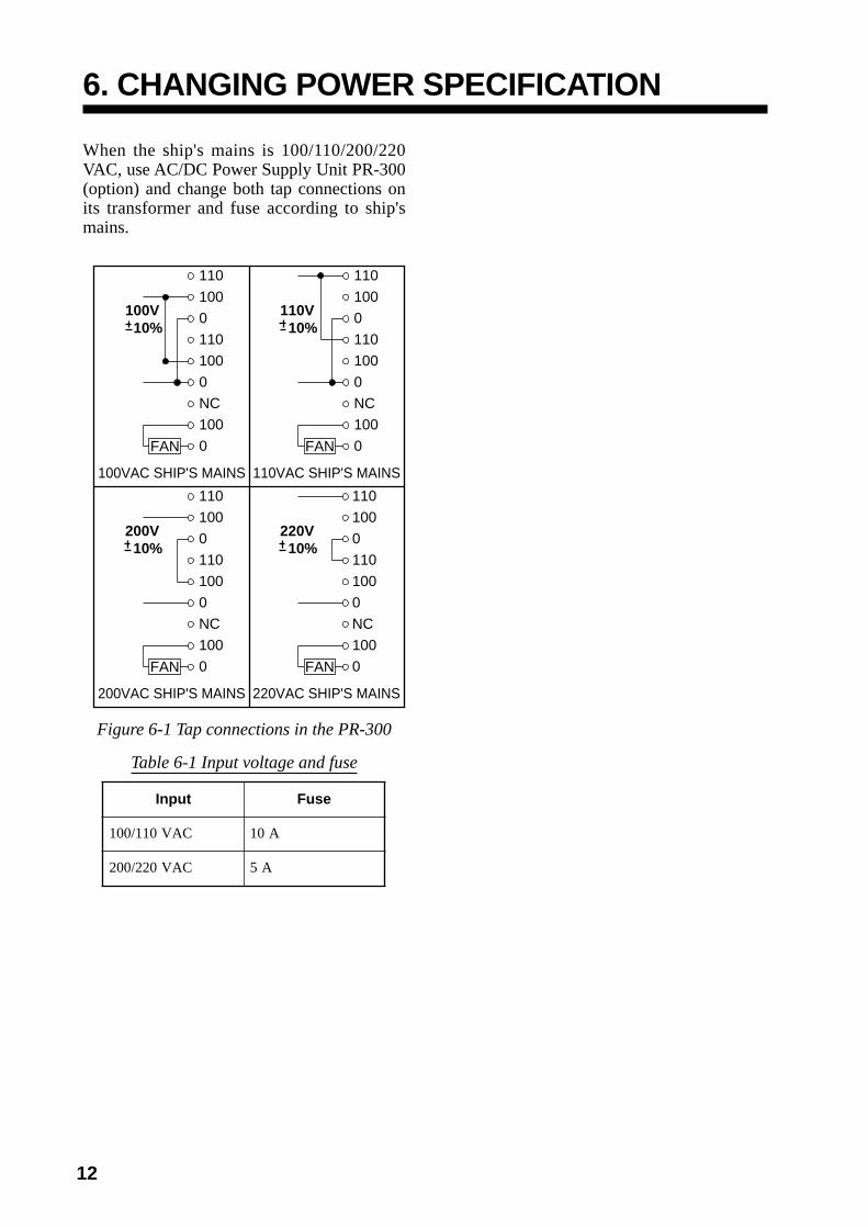
When the ship's mains is 100/110/200/220VAC, use AC/DC Power Supply Unit PR-300(option) and change both tap connections onits transformer and fuse according to ship'smains.
110
100100V 10%
0
110
100
0
NC
100
0FAN
100VAC SHIP'S MAINS
110
100110V 10%
0
110
100
0
NC
100
0FAN
110VAC SHIP'S MAINS
110
100200V 10%
0
110
100
0
NC
100
0FAN
200VAC SHIP'S MAINS
110
100220V 10%
0
110
100
0
NC
100
0FAN
220VAC SHIP'S MAINS
Figure 6-1 Tap connections in the PR-300
Table 6-1 Input voltage and fuse
tupnI esuF
CAV011/001 A01
CAV022/002 A5