Installation Manual For Dimension4™ Symphony …msr-inc.com/downloads/pdf_files/120716 D4 Symphony...
19
Installation Manual For Dimension4™ Symphony Home Cinema Acoustical Tuning System Distributed by Media Specialty Resources, Inc. 61 A Galli Drive Novato CA 94949, USA Toll Free: 1-800-497-2087 Fax: 1-415-883-8147 Email: [email protected] www.msr-inc.com
Transcript of Installation Manual For Dimension4™ Symphony …msr-inc.com/downloads/pdf_files/120716 D4 Symphony...

Installation Manual For
Dimension4™ Symphony Home Cinema Acoustical Tuning System
Distributed by Media Specialty Resources, Inc. 61 A Galli Drive Novato CA 94949, USA Toll Free: 1-800-497-2087 Fax: 1-415-883-8147 Email: [email protected] www.msr-inc.com

2
Introduction Every home cinema is affected by room acoustics. Allow the articulation, tonal balance, and clarity of your loudspeakers to be heard. Don’t chance missing important elements within the soundtrack. The Dimension4 Symphony system is a high quality, easy-to-install acoustical tuning solution for home cinemas and listening rooms. Based on scientifically-designed building blocks including Absorbers, Diffusers, Corner Traps, and Ceiling Panels, Symphony is calculated to provide optimum absorption and diffusion and is a full-frequency component solution. Dimension4 Symphony modules can be installed in minutes by observing the following simple instructions.

3
Modules AMI Absorber Construction: A 24” x 24” x 4” (60cm x 60cm x 10cm) module consisting of a mineral wool core clad in a fiberglass lining, wrapped in fabric, and embedded in a wood substructure with high frequency filtering. Benefits: Provides absorption down to 250Hz with tapered high frequency control
C-Fuser Construction: A 24” x 24” x 6” (60cm x 60cm x 15cm) 2D diffuser module made of solid wood with a Helmholtz resonator center. Benefits: Provides horizontal scattering down to 800Hz combined with low frequency absorption
Corner Trap Construction: A 24” x 48” x 2” (60cm x 90cm x 5cm) mitered-edged panel consisting of a mineral wool core clad in a fiberglass lining and wrapped in fabric Benefits: Provides bass absorption down to 60Hz by means of corner mounting
Ceiling Panel Construction: A 24” x 48” x 1” (60cm x 120cm x 2.5cm) flat panel consisting of a mineral wool core clad in a fiberglass lining wrapped in fabric, with hanging hoops Benefits: Provides absorption down to 300Hz
Trifuser-S 3D Mid Frequency Diffusers Module: Construction: A 24” x 24” x 4” (60cm x 60cm x 10cm) 3D diffuser module made of solid wood open equilateral triangle cells. Benefits: Provides hemispherical scattering down to 800Hz combined with low frequency absorption.
Trifuser-SA 3D Mid Frequency Diffusers with Absorption: Construction: A 24” x 24” x 4” (60cm x 60cm x 10cm) 3D diffuser module made of solid wood damped equilateral triangle cells. Benefits: Provides hemispherical scattering down to 800Hz combined with mid-frequency absorption

4
Tools and Materials Required Screwdriver (Philips or standard depending on the type of fastener) Hammer 25 Foot (8m) Measuring Tape Pencil Masking Tape Bubble or Laser Level Mirror Screws or other appropriate fasteners for your wall surface (E-Z Anchor works
well for sheetrock) Screw Hooks
Panel Placement Symphony systems are suitable for a wide variety of room sizes. The bigger the room, the larger the number of treatment panels. The following diagrams show sample room layouts for four ranges of room sizes. For best results, you will need to find the first reflection points between the speakers and the listening position. (See instructions later in this manual.)
Room Size (ft2) (m2) Kit Number of Modules 100-200 10-20 150 System 28 200-300 20-30 250 System 35 300-400 30-40 350 System 43 400-500 40-50 450 System 50 500-600 50-60 550 System 60 600-700 60-70 650 System 73

5
100-200 ft2 (10-20 m2) Room Using Dimension4 Symphony 150 System
Dimension4 Symphony 150
10 AMI Absorbers4 C-fusers
6 Trifuser-SA Diffusers4 Trifuser-S Diffusers
2 Corner Traps2 Ceiling Panels
Fig 1

6
200-300 ft2 (20-30 m2) Room Using Dimension4 Symphony 250 System
Dimension4 Symphony 250
14 AMI Absorbers4 C-fusers
8 Trifuser-SA Diffusers4 Trifuser-S Diffusers
2 Corner Traps3 Ceiling Panels
Fig 2
7
300-400 ft2 (30-40 m2) Room Using Dimension4 Symphony 350 System
Dimension4 Symphony 350
16 AMI Absorbers6 C-fusers
8 Trifuser-SA Diffusers6 Trifuser-S Diffusers
4 Corner Traps3 Ceiling Panels
Fig 3

8
400-500 ft2 (40-50 m2) Room Using Dimension4 Symphony 450 System
Dimension4 Symphony 450
18 AMI Absorbers8 C-fusers
8 Trifuser-SA Diffusers8 Trifuser-S Diffusers
4 Corner Traps4 Ceiling Panels
Fig 4
9
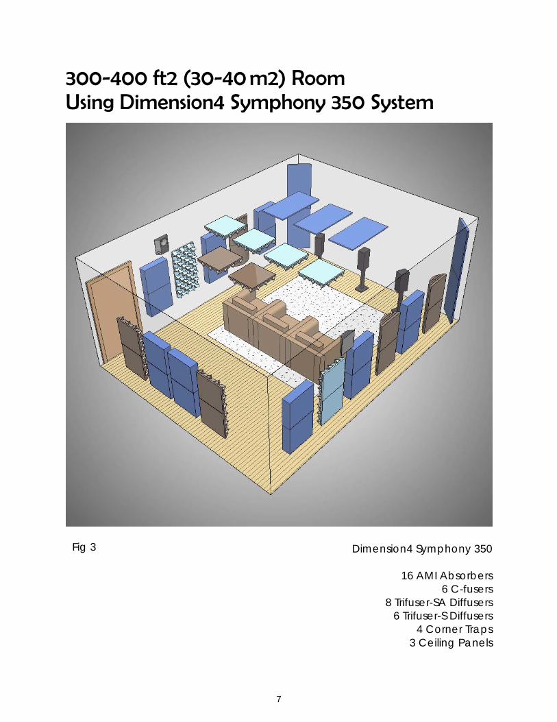
500-600 ft2 (50-60 m2) Room Using Dimension4 Symphony 550 System
Dimension4 Symphony 550
22 Absorbers10 C-fuser8 Trifuser-S
10 Trifuser-SA6 Corner Traps
4 Ceiling Panels
10
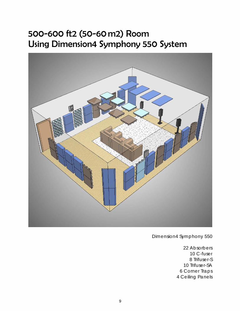
600-700 ft2 (60-70 m2) Room Using Dimension4 Symphony 650 System
Dimension4 Symphony 650
23 Absorbers10 C-fusers16 Trifuser-S
10 Trifuser-SA8 Corner Traps
6 Ceiling Panels
11
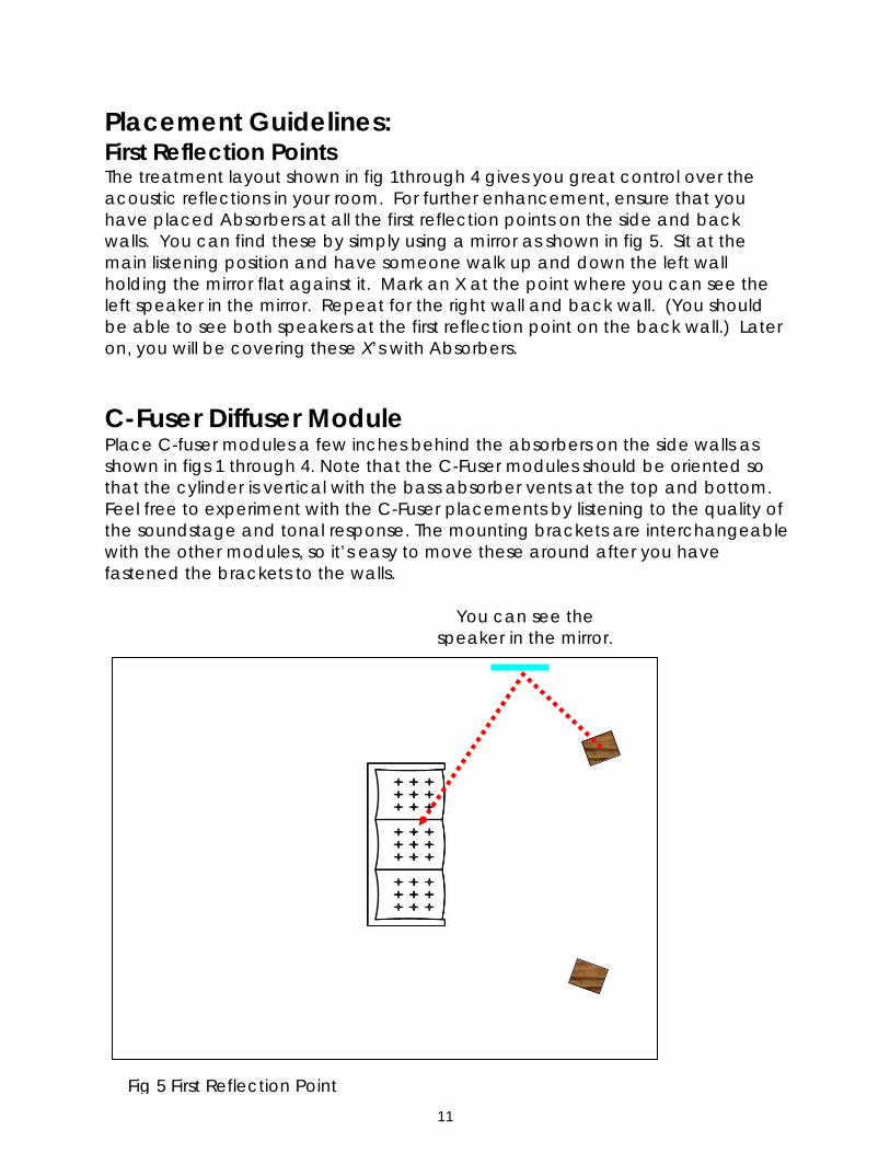
Placement Guidelines: First Reflection Points The treatment layout shown in fig 1through 4 gives you great control over the acoustic reflections in your room. For further enhancement, ensure that you have placed Absorbers at all the first reflection points on the side and back walls. You can find these by simply using a mirror as shown in fig 5. Sit at the main listening position and have someone walk up and down the left wall holding the mirror flat against it. Mark an X at the point where you can see the left speaker in the mirror. Repeat for the right wall and back wall. (You should be able to see both speakers at the first reflection point on the back wall.) Later on, you will be covering these X’s with Absorbers.
C-Fuser Diffuser Module Place C-fuser modules a few inches behind the absorbers on the side walls as shown in figs 1 through 4. Note that the C-Fuser modules should be oriented so that the cylinder is vertical with the bass absorber vents at the top and bottom. Feel free to experiment with the C-Fuser placements by listening to the quality of the soundstage and tonal response. The mounting brackets are interchangeable with the other modules, so it’s easy to move these around after you have fastened the brackets to the walls.
Fig 5 First Reflection Point
You can see the speaker in the mirror.

12
Trifuser-S and Trifuser-SA 3D Diffuser Module Place 3D Diffuser Modules towards the rear portions of the room on the side walls and the back wall as shown in fig 1 through 4. Also place 3D diffusers on the ceiling at locations behind the main listening position. Feel free to experiment with the Trifuser-S and Trifuser-SA placements by listening to the quality of the soundstage and tonal response. The mounting brackets are interchangeable with all the other modules, so it’s easy to move these around after you have fastened the brackets to the walls.
Corner Trap The Corner Trap is a mid to low frequency absorption device with an effective bandwidth down to 60Hz. Corner Trap panels should be placed in the front corners of the room (angled between the front/side wall) at the same height as all other panels. If the corners aren't available, place Corner Traps along the front wall/ceiling junction.
Ceiling Panel The floating Ceiling Panel is our solution to unwanted reflections from the ceiling. Research has shown that ceiling reflections are detrimental to good sound reproduction. We recommend hanging Ceiling Panels at the first reflection points for the front speakers as shown in Fig 6.
Fig 6 Ceiling First Reflection
First Reflection Point
Screw hooks go at the corners.

13
Optional Special Products SpringTrap® A spring-loaded bass trap, the SpringTrap is our solution to very low frequency room resonance buildup in the range of 40 to 100Hz. This unique patented design, which received the Mix Magazine Certified Hit award, was presented as a research paper at AES in Amsterdam 2003. It consists of a triple-ported resonator system, activated by a large spring-loaded pistonic diaphragm. The SpringTrap should be placed in an inconspicuous area in front of the mix position or in a corner on the floor. Experiment with the placement of the SpringTrap. Since it is a triangular device, you should have no trouble finding areas to place it. Play bass-heavy program material and listen to the bass sound pressure at all the corners of the room. The louder the sound pressure, the stronger the standing wave resonance at that location, and the more effective the SpringTrap will be. The SpringTrap is not included in the Dimension4 Symphony system. It is available as optional amendment.

14
Module Installation Now that you’ve located the recommended placement for each module, you can move on to the actual installation. Absorbers and diffuser modules are hung from the walls using the supplied mounting bracket. There are two per module. Please contact MSR immediately if any of the cleats are missing. See the instruction below for the individual modules.
Preparing the mounting bracket locations The mounting brackets will typically be at the same heights throughout the room. We recommend using a laser level to mark the heights of all the top and bottom brackets so as to ensure a level installation. Note that some ceilings and floors are not flat and you may need to compensate for the differences.
Toe-screw through edge of module and into ceiling along an edge that is least visible in the studio (front wall). This will ensure panel never slides out of mounting brackets.
Install mounting bracket of module onto ceiling using drywall anchor and appropriate screw. Slide module onto both of the mounting bracket channels so it is secure on the ceiling.
Mounting bracket at backside of module
Support bracket mounted to wall
Fastening screw
ZSound Module (see below for various types
ZSound Module (see below for various types
Section View
Ceiling Panel Installation details
ZSound Module (see left for various types ZSound Module Samples (Installation diagram above applies to all modules below)

15
Absorbers Position the Absorbers based on the diagrams and instructions from the
preceding pages. Mark the first reflection points as described earlier. Determine the exact location on the wall for each Absorber. They are usually
placed in vertical pairs. The top edge of the top module should be 72 inches (183cm) from the floor. The bottom edge of the bottom panel should be about 24 inches (60cm) from the floor. The middle of the panel pair should line up with the first reflection point as marked on the wall.
Attach one or two mounting brackets to the wall per Absorber using screws into studs, wallboard anchors and screws, or other appropriate fasteners. The thin flange of the mounting bracket should point toward the ceiling. The lower edge of the top bracket is 3 1/8 inches (8cm) down from the top of the module. The lower edge of the bottom bracket is 19 5/8 inches (50cm) down from the top of the module.
Lift the Absorber up and over the mounting brackets and drop it into the brackets, applying gentle downward pressure until the module is caught securely. Note that the Absorber will travel down about ½ inch (1cm) from where it started. Use a bubble or laser level to make sure the Absorber hangs straight.
Diffuser Modules Position the Diffuser Modules based on
the diagrams and instructions from the preceding pages.
Determine the exact location on the wall for each Diffuser Module. They are usually placed in vertical pairs. The top edge of the top module should be 72 inches (183cm) from the floor. The bottom edge of the bottom panel should be about 24 inches (60cm) from the floor. The middle of the panel pair should line up with the first reflection point as marked on the wall.
Attach one or two mounting brackets to the wall per Diffuser Module using screws into studs, wallboard inserts and screws, or other appropriate fasteners. The thin flange of the mounting bracket should point toward the ceiling. The lower edge of the top bracket is 3 1/8 inches (8cm) down from the top of the module. The lower edge of the bottom bracket is 19 5/8” inches (50cm) down from the top of the module.
Lift the Diffuser Module up and over the mounting brackets and drop it into the brackets, applying gentle downward pressure until the module is caught securely. Note that the Diffuser Module will travel down about ½ inch (1cm) from where it started. Use a bubble or laser level to make sure the Diffuser Module hangs straight.
Trifuser

16
Corner Traps Position the Corner Traps based on the diagrams and instructions from the
preceding pages. In order to hang each Corner Trap in the corners of the room, you will need to
use two corner braces supplied with the system as shown in fig 7. These braces will span the corner, the impale clips will attach to them, and the Corner Trap will hang from the impale clips. Install one brace centered at 36 inches (90cm) from the floor. Install the second brace centered at 60 inches (150cm) from the floor. Drive fasteners into the lateral walls that the brace spans.
Attach two impale clips to the top brace and two to the bottom using screws. The spiky flanges should point toward the ceiling as shown in fig 7. The position of the impale clips along the brace does not really matter.
Press the Corner Trap against the impale clips and apply gentle downward pressure until the panel is caught securely. Use a bubble or laser levels to make sure the Corner Trap hangs straight. Note that the Corner Trap will travel down about ½ inch (1cm) from where it started. Thus, you should press it
Fig 7

17
Ceiling Panels The Ceiling Panels are hung
using screw hooks. You will need to supply a total of 4 screw hooks per panel (not included with the Symphony kit).
Position the Ceiling Panels based on the diagrams and instructions from the preceding pages.
Mark the first reflection points as described earlier.
Determine the exact location on the ceiling for each Ceiling Panel. The center of each panel should line up with one of the first reflection points as marked on the ceiling.
Screw 4 open screw hooks into the ceiling in a rectangular pattern 36 inches by 12 inches (90 x 30 cm), 6 inches (15cm) inside each edge of the Ceiling Panel. Make sure that you secure the screw hooks in joists or use wallboard anchors. After all 4 screw hooks are installed; simply lift the wire loops (pre-installed in the Ceiling Panel) over the hooks. The Ceiling Panel will float a few inches (cm) below the ceiling.
Care Instructions The fabric surfaces may be cleaned with mild, water-free solvents or water-based cleaning agents or foam. The wood surfaces may be cleaned with a lightly dampened cloth, or will oil soap.
Spares If any mounting hardware, panel parts, or extra printed material are needed, please call MSR.
Cable loop on back side of cloud panels hang off screw hooks
Standard screw hook secures into ceiling assembly. If wood backing is not available, utilize sheetrock anchor system prior to installing screw hooks

18
Shipping Weight & Dimensions Domestic (U.S.A) Item Units Weight (lbs) Box Dimensions (in)
Per Box Per Box L W H
AMI 1 25 27 27 6
Trifuser-SA 2 29 27 27 11
Trifuser-S 2 25 27 27 11
C-Fuser 1 25 27 27 8
Corner Traps 2 36 49 26 26
Clouds 2 34 50 27 6
International Item Units Weight (Kg) Box Dimensions (cm)
Per Box Per Box L W H
AMI 1 11 68 68 13.5
Trifuser-SA 2 13 68 68 28
Trifuser-S 2 11 68 68 28
C-Fuser 1 11 68 68 20
Corner Traps 2 16 124 66 66
Clouds 2 15 127 68 15
Warranty All Dimension4 Symphony modules are warranteed to be free of manufacturing defects for a period of 12 months from the date of purchase.

19
Media Specialty Resources, Inc. 61 A Galli Drive Novato CA 94949, USA
Toll Free: 1-800-497-2087 Fax: 1-415-883-8147
Email: [email protected] www.msr-inc.com
Dimension4, Dimension4 Symphony, and SpringTrap are trademarks of MSR Inc. Copyright 2012. Dimension4 Symphony is a quality product from Media Specialty Resources, Inc. Specifications are subject to change without notice 120709 Dimension4 Symphony Instruction Manual v2_8.5x11. Issue date July 9, 2012